1
~
Onan
Service Manual
ua
ls
OT Ill
J
.c
om
.c
ar
tM
an
Transfer Switch
40 to 1 000 Am eres
.E
lec
tri
ca
lP
c
w
1
ww
c
Printed in U.S.A.
Begin Spec G
962-0512
11-92
w
ww
.E
lec
tri
an
tM
ar
lP
ca
ua
ls
.c
om
1
TITLE
PAGE
SAFETY PRECAUTIONS
INTRODUCTION
.
.
.
About This Manual
.
.
.
.
.
.
.
.
.
.
.
.
.
.
.
.
.
.
.
.
.
.
.
.
.
.
.
.
.
.
.
.
.
.
.
.
.
.
.
.
.
.
.
.
.
.
.
.
.
.
.
.
.
.
.
.
.
.
.
.
.
.
.
.
.
.
.
.
.
.
.
.
.
.
.
. . .
.
..
.
.
.
.
.
.
.
.
iii
1-1
.
.
.
.
................................................ 1-1
.
.
.
.
.......................................... 1-1
Automatic Transfer Switches
Model Identification
.
.
.
Transfer Switch Application
Cabinet
.
ua
ls
SECTION
.c
om
Table of Contents
.
........................................ 1-2
...................... . ......................... 1-2
......................................................... 1-2
Transfer Switch Assembly ................. . ......................... 1-4
.
Operation
.
.
.
.
.
.
.
.......................... . ...................... 1-4
.
.
.
.
.
Preventive Maintenance
.
.
.
.
.
.
.
.
.
.
.
.
.
.
.
.
.
.
.
.
.
.
.
.
.
.
.
an
Electronic Control
Removing and Replacing Electronic Control Components
Feature Description I Feature Option
ELECTRONIC CONTROL SYSTEM
.
.
.
.
.
.
.
.
.
.
.
.
.
.
.
.
.
.
.
1-7
.
.
................. 1-10
................................. 1-11
.................................... 2-1
tM
2.
.
............................................ 1-9
Introduction ........................ . .............................. 2-1
Power Sentry Control
.
.............................................. 2-1
ar
Accessory Control Panel and Terminal Blocks
Optional Control Modules and Accessories
Control System Operation
.
.
.
........................... 2-7
............................. 2-8
.......................................... 2-17
.
lP
Adjusting Power Sentry Modules
.................................... 2-22
Adjusting Optional Control Modules and Accessories
3.
TROUBLESHOOTING
.
.
.................... 2-24
............................................... 3-1
ca
Transfer Switch Does Not Retransfer
.
.
. .
.
.
.
.
.
.
.
.
. .
.
.
.
.
.
.
.
.
.
.
.
.
.
.
.
.
.
.
.
.
.
3-2
Source 1 Voltage Sensor Does Not Sense Voltage ........................ 3-4
Transfer Switch Does Not Transfer
.
.
.
.
.
.
. .
.
.
.
.
.
Source 2 Voltage Sensor Does Not Sense Voltage
tri
Generator Set Does Not Crank (Two-Wire
Sta rt)
TRANSFER SWITCH ASSEMBLY
.
.
.
.
.
.
.
.
.
.
.
.
.
.
.
.
.
.
.
.
.
.
.
.
.
.
.
.
.
.
.
.
3-5
.
.
.
.
.
.
.
.
.
.
.
.
.
.
3-7
.
........................ 3-9
...................................... 4-1
......................................................... 4-1
lec
General
. .
.......................... 3-8
Generator Set Does Not Crank (Three-Wire Start)
4.
.
Disconnect AC Power
.
.............................................. 4-1
Reconnecting AC Power (When Finished)
.
.............................. 4-1
Linear Actuator Removal and Replacement (40 to 125 Amperes)
.
.
.
(40 to 125 Amperes)
(40 to 125 Amperes)
.
.
.
.
.E
Block and Crossbar Removal and Replacement
Auxiliary Switch Removal and Replacement
Linear Actuator Removal and Replacement (150 to 260 Amperes)
.
w
ww
.
.
.
.
.
.
4-1
........ 4-4
........... 4-9
.
.
.
.
.
.
.
.
.
.
.
4-7
.
.
.
.
.
Auxiliary Switch Removal and Replacement (150 to 260 Amperes)
. . 4-12
.
......... 4-15
.......... 4-17
Block and Crossbar Removal and Replacement (300 to 600 Amperes)
Auxiliary Switch Removal and Replacement (300 to 600 Amperes)
.
.
Block and Crossbar Removal and Replacement (150 to 260 Amperes)
Linear Actuator Removal and Replacement (300 to 600 Amperes)
.
.
.
.
.
.
.
.
..
.
4-20
.
.
.
.
.
.
4-23
.
Linear Actuator Removal and Replacement (800 and 1000 Amperes) ........ 4-25
Block and Crossbar Removal and Replacement (800 and 1000 Amperes)
.
.... 4-28
Auxiliary Switch Removal and Replacement (800 and 1000 Amperes) . ... .. . . 4-32
(Continued)
PAGE
TITLE
GENSET-TQ-GENSET
Introduction
Cabinet
.
.
.
.
.
.
.
.
.
.. ................... ... ....................... 5-1
.
.
.
.
.
.
•
.
.
.
.
.
.
.
Electronic Control System .
Operation
.
.
.
.
.
.
.
•
.
.
.
.
.
.
.
.
.
.
.
.
.
.
.
.
.
.
.
.
.
.
.
.
.
.
.
.
.
.
.
.
.
.
5-1
Introduction
.
.
.
.
.
.
.
.
.
.
.
.
.
.
.
.
.
.
.
.
.
.
.
.
.
.
.
.
.
.
.
.
.
.
.
.
.
.
.
.
.
.
.
.
.
.
.
.
.
.
.
.
.
.
.
.
.
.
.
.
.
5-3
.
.
.
.
.
.
.
.
.
.
.
.
.
.
.
.
.
.
.
.
.
.
.
.
.
.
5-3
.... ...... .. ................................. .... 5-15
UTILITY-TO-UTILITY
.
.
.................................... .......... .. ...... 5-14
Troubleshooting
Cabinet
.
......... ..... ................................ . .......... 5-2
Transfer Switch
6.
.
ua
ls
5.
.
.
.
.
.
.
.
.
.
.
.
.
.
.
.
.
.
.
.
.
.
.
.
.
.
.
.
.
.
.
.
.
.
.
.
.
.
.
.
.
.
.
.
.
.
.
.
.
.
.
6-1
.
.
.
.
.
.
.
.
.
.
.
.
.
.
.
.
.
.
•
.
...... ............................. 6-1
.
.
.
.
.
•
.
.
.
.
.
.
.
.
.
.
.
.
.
.
.
.
an
SECTION
.c
om
Table of Contents
.
.
.
.
.
.
.
.
.
.
.
.
.
.
.
.
.
.
.
.
.
.
.
•
.
........ 6-2
Transfer Switch . .............. . .... ........ . .......... ...... . . ..... 6-3
Operation
.
.
.
.
.
Troubleshooting
7.
.
.
.
.
.
.
.
.
.
.
.
.
.
.
..
NONAUTOMAnCJREMOTE
Cabinet
.
.
.
.
.
.
.
.
.
.
.
.
.
.
.
.
.
.
.
.
.
.
.
.
.
.
.
.
.
.
.
.
.
.
.
.
.
.
.
.
.
.
.
6-3
.
.
.
.
•
.
.
.
.
.
.
.
.
.
.
.
.
.
.
.
.
.
.
.
.
.
.
.
.
.
•
.
.
.
.
.
.
.
.
.
.
.
.
6-8
.
.
.
.
.
.
.
.
.
.
.
.
.
.
.
.
.
.
.
.
.
.
.
.
.
.
.
.
.
.
.
.
.
.
.
.
.
.
.
.
.
.
.
6-8
.
.
.
.
.
.
•
.
.
.
.
.
.
.
.
.
.
.
.
.
.
.
.
.
.
.
.
.
.
.
.
.
.
.
.
.
.
.
.
.
.
.
.
7-1
............. ............ .................. ...... ..... 7-1
......... ..... .................. ......................... 7-2
Transfer Switch
Optional Control Components
.
..................... .. . ................ 7-5
Operation
.
.
.
.
.
.
.
.
.
.
.
.
.
.
.
.
.
.
.
lP
.
.
.
.
.
.
.
.
.
.
.
.
.
.
.
.
.
.
.
.
.
.
.
.
.
.
.
.
.
.
.
.
.
.
.
.
.
.
.
.
.
.
.
.
.
.
.
.
.
.
.
.
.
.
.
.
.
.
.
.
.
.
•
.
.
.
.
.
.
.
.
.
.
.
.
.
7-7
.......................... ..... 8-1
Mother Board 300-3953 (Utility-to-Generator Set)
.
.
.
......... ........... ........ ...................... 7-8
Mother Board 300-3267 (Utility-to-Utility)
.
.
.
.
.
.
.
ca
.
.
.
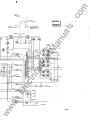
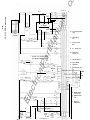
SCHEMA ncs AND WIRING DIAGRAMS
.
.
7-3
.
Troubleshooting
8
.
ar
Introduction
.
tM
Electronic Control System .
.
........................ 8-3
............................... 8-4
Mother Board 300-3090 (Utility-to-Generator Set)
.
. . . . . . . . . . . . . . . . . . . . . . . . 8-5
tri
626-1762 (Sheet 1 of 5) .............. ............................... 8-6
626-1762 (Sheet 2 of 5) .............................. ............... 8-7
626-1762 (Sheet 3 of 5)
.
................................. ........... 8-8
.
... ............ ............................. 8-9
626-1762 (Sheet 5 of 5)
.
................................. .......... 8-10
.E
lec
626-1762 (Sheet 4 of 5)
Open Construction Wiring Diagrams
................................ . 8-11
IAWARNINGI
INCORRECT SERVICE OR REPLACEMENT OF PARTS CAN RESULT IN
DEATH, SEVERE PERSONAL INJURY, AND/OR EQUIPMENT DAMAGE.
SERVICE PERSONNEL MUST BE QUAL/RED TO PERFORM ELECTRICAL
AND/OR MECHANICAL SERVICE.
w
ww
.
ii
.c
om
Safety Precautions
If the cabinet must be opened for any reason:
This manual includes the following symbols to indi
cate potentially dangerous conditions. Read the
manual carefully and know when these conditions
exist. Then take the necessary steps to protect per
sonnel and the equipment.
P'!'t•NUi)¥1;1 This symbol warns of Immediate
hazards that will result In severe persona/Injury
or death.
IAWARNINGI This symbol refers to a hazard or
unsafe practice that can result In severe per
sona/ Injury or death.
IACAUTION I This symbol refers to a hazard or
unsafe practice that can result In personal In
jury or product or property damage.
High voltage in OT transfer switch component� pre
sents serious shock hazards that can result 1 n se
vere personal injury or death. Read and follow
these suggestions.
Keep the transfer switch cabinet closed and locked.
Make sure only authorized personnel have the
cabinet and operational keys.
Due to the serious shock hazard from high voltages
within the cabinet, all service and adjustments to
the transfer switc h must be performed only by an
electrician or authorized service repre sentative.
ua
ls
1. Move the operation selector switch on the gen
erator set or Stop/Auto/Handcrank switch on
the automatic transfer switch (whichever ap
plies) to Stop.
2. Disconnect
the starting batteries of the gen
erator set (remove the ground [ -] lead first).
AC power to the automatic transfer
switch. If the instructions require otherwise,
use extreme caution due to the danger of
shock hazard.
Place rubber insulative mats on dry wood platforms
over metal or concrete floors when working on any
electrical equipment. Do not wear damp clothing
(particularly wet shoes) or allow skin surfaces to be
damp when handling any electrical equipment.
Jewelry is a good conductor of electricity and
should be removed when working on the electrical
equipment.
Do not work on this equipment when mentally or
physically fatigued, or after consuming alcohol or
any drug that makes the operation of equipment
unsafe.
ww
w
.E
lec
tri
ca
lP
ar
tM
an
3. Remove
iii
OT3-UG-3
w
ww
.E
tri
lec
an
tM
ar
lP
ca
ua
ls
.c
om
.c
om
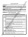
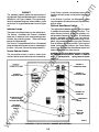
1. Introduction
ABOUT THIS MANUAL
NORMAL
ua
ls
This manual contains service procedures for an OT
transfer switch. Sections 1 , 2, 3, and 4 cover the
utility-to-generator set automatic transfer switch.
Although much of the information on theory of op
eration, Power Sentry® calibration, and trouble
shooting in sections 1 , 2, and 3 is applicable to gen
erator set-to-generator set, utility-to-utility, and
nonautomatic/remote configurations; there are
several significant differences.
Refer to section 5 for an overview of the generator
set-to-generator set transfer switch.
Refer to section 6 for an overview of the utility-to
utility transfer switch.
Refer to section 7 for an overview of the non
automatic/remote transfer switch.
Refer to the schematic and wiring diagram package
that was shipped with the transfer switch for spe
cific information about its configuration.
Section 4 of this manual covers transfer switch as
sembly service procedures for all configurations.
Use normal and necessary safety precautions be
fore starting any service procedures. Identify all
hazards by referring to the Safety Precautions
printed inside the front cover and observe all warn
ings and cautions within the manual. W henever
troubleshooting, remember that the generator set,
transfer switch, and utility power source are all in
terdependent.
I
I
�
I
I
I
tri
ca
lP
ar
tM
an
I
I
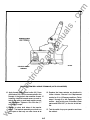
TRANSFER SWITCH APPLICATION
w
.E
lec
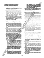
Transfer switches are an essential part of a build
ing's standby or emergency power system. The
Normal power source, commonly the utility line, is
backed up by an Emergency power source, often a
generator set. The transfer switch supplies the
electrical load with power from one of these two
power sources.
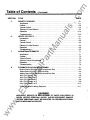
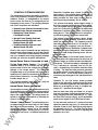
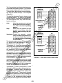
The load is connected to the common of the trans
fer switch (Figure 1-1 ). Under normal conditions,
the load is supplied with power from the Normal
source (as illustrated). If the Normal power source
is interrupted, the load is transferred to the Emer
gency power source. W hen Normal power returns,
the load is retransferred to the Normal power
source. The transfer and retransfer of the load are
the two most basic functions of a transfer switch.
ww
1
.---�
Power Sentry is a registered trademark of Onan Corporation.
1 -1
I
I
I
L-
r
EMERGENCY
LOAD
9C1101
FIGURE 1 ·1 . LOAD TRANSFER SWITCH
(TYPICAL FUNCTION)
.c
om
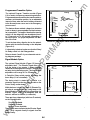
AUTOMATIC TRANSFER SV\nTCHES
nected to the load. Only one of these two lamps
can be lit.
Automatic transfer switches, capable of automatic
operation without operator involvement, perform
the following basic functions:
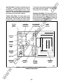
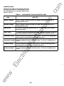
Test/Normai/Retransfer Switch
This switch has three positions. In the Normal posi
tion, the transfer switch is set for automatic opera
tion. Moving the switch to Test sends a start signal
to the generator set. After the transfer time delay,
the generator set will assume the load-provided
that the Test With/Without Load switch (Figure 1-3)
is in the With Load position.
1 . Sense the interruption of t he Normal power
source.
ua
ls
2. Send a start signal to the generator set (Emer
gency power source).
3. Transfer the load to the Emer!}ency power
source.
Moving the switch to Normal causes the load to
transfer to the Normal power source after the
retransfer ti me delay. To avoid the delay and cause
a fast retransfer of load to the Normal power
source, move the switch to the Retransfer position.
4. Sense the return of the Normal power source.
Retransfer the load to the Normal power
source.
an
5.
6. Send a stop signal to the generator set.
Optional Meter Package
MODEL IDENTIFICATION
tM
The optional meter package includes an AC amme
ter, an AC voltmeter, a frequency meter, and a
phase selector switch.
Identify your model by referring to the Model and
Specification number as shown on th1� nameplate.
Electrical characteristics are shown �o n the lower
portion of the nameplate, which is located on the
cabinet door. Refer to the last page of this section
for a list of feature/option codes.
ar
AC Voltmeter: T he voltmeter measures line-to-line
voltage of the selected power source.
AC Ammeter. The ammeter measures the line cur
rents of the load.
Frequency Meter: This meter measures the out
put frequency of the selected power source in
hertz .
tri
CABINET
ca
lP
If it is necessary to contact a dealer or the factory
regarding the transfer switch, always �Jive the com
plete Model, Specification, and Serial number as
listed on the nameplate. This information is neces
sary to properly identify your unit among the many
types manufactured.
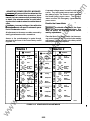
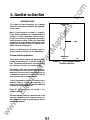
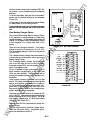
The standard cabinet meets the requirements of
the National Electrical Manufacturers Association
(NEMA) for a UL Type 1 cabinet. This 1ype is desig
nated as a general-purpose, indoor cabinet. The
door of a typical utility-to-generator set cabinet is
shown in Figure 1-2.
On transfer switches with an AC ammeter, the load
wires must each pass through a current trans
former.
lec
Optional Auto/Manual Switch
(Utility-to-Generator Set)
The Auto/Manual switch is used to enable or dis
able the automatic retransfer function. This switch
has two positions. In the Auto position, normal auto
matic retransfer is enabled. In the Manual position,
automatic retransfer (from a functioning generator
set back to utility power) is disabled; only manual
retransfer (using the Test/Normai/Retransfer
switch) is possible. In the event of generator set
failure, however, the Power Sentry control logic will
ignore the Auto/Manual switch and initiate retrans
fer to utility power.
.E
Refer to section 5, 6, or 7 If applicable.
Indicator Lamps
w
There are four indicator lamps on the cabinet door.
The Normal Available and Emergency Available
lamps are lit whenever their corresponding power
sources (utility or generator set) ar�e producing
power. These two lamps can be lit simultaneously.
ww
Phase Selector Switch: This switch is used to se
lect the source and phase to be measured.
Refer to section 6 for a description of the optional
Auto/Manual switch on utility-to-utility transfer
switches.
The Normal Connected and Emer9ency Con
nected lamps indicate which power source is con-
1 -2
.c
om
EMERGENCY
CONNECTED LAMP
NORMAL
CONNECTED LAMP
NORMAL
AVAILABLE LAMP
ua
ls
EMERGENCY
AVAILABLE LAMP
an
OPTIONALAC
VOLTMETER
ar
�,�------�@
OPTIONAL FREQUENCY
METER
TEST/NORMAL/
RETRANSFER SWITCH
0
ca
lP
OPTIONAL
AUTO/MANUAL
SWITCH
tM
PHASE SELECTOR
SWITCH (FOR
OPTIONAL METERS)
OPTIONAL AC
AMMETER
ww
w
.E
lec
tri
FIGURE 1 -2. UTIUTY-TO-GENERATOR SET TRANSFER SWITCH
CABINET EXTERIOR
1-3
M1694-48
.c
om
S7, S8, and S9 are actuated. Refer to Section 2
and to the schematic and wiring diagram package
for more information on the functions of the individ
ual switches.
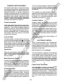
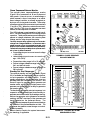
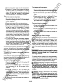
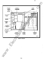
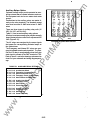
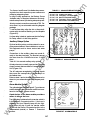
TRANSFER SWITCH ASSI::MBLY
The transfer switch (Figure 1 -3) opens and closes
the contacts that transfer the load between Normal
and Emergency power. The transfer switch is me
chanically interlocked to prevent simultaneous
closing to both power sources. The main parts of
the transfer switch discussed here are the contact
assemblies, linear actuator, capac:itor(s), Motor
Disconnect switch, auxiliary switches, and auxiliary
contacts. Transfer switch assembly' maintenance
procedures are described in Section 4.
ua
ls
The schematic and wm ng diagram package is
shipped with the transfer switch. Contact your dis
tributor if you do not have a set of drawings. Refer
to Section 4 for a description of auxiliary switch
maintenance procedures.
Auxiliary Contacts
Auxiliary contacts are provided on the Normal
(switch S2) and Emergency (switch S6) sides of the
transfer switch. They are actuated by operation of
the transfer switch during transfer and retransfer.
The Normal side auxiliary contact switch is actu
ated when the transfer switch is in the Normal posi
tion. The Emergency side auxiliary contact switch
is actuated when the transfer switch is in the Emer
gency position.
tM
The transfer switch either has three or four poles.
Three pole transfer switches are provided with a
neutral bar. The contact assemblies make and
break the current flow. When closed to either the
Normal or the Emergency power source, the con
tacts are mechanically held. A mechanical inter
lock prevents them from closing to both power
sources at the same time.
an
Contact Assemblies
The auxiliary contacts have current ratings of 1 0
amperes at 250 VAC.
ar
Linear Actuator
The linear actuator is a linear inductii on motor that
moves the contact assemblies between the Normal
power source and the Emergency power source.
U near actuator operation is initiated automatically
with automatic transfer switches. Manual operation
of the transfer switch is also possible. Refer to
Manual Operation.
ELECTRONIC CONTROL
ca
lP
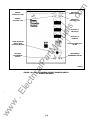
Figure 1-3 shows the interior of a 1 25-ampere util
ity-to-generator set transfer switch. Due to differ
ences in cabinet sizes, the location of some of the
optional modules in your transfer switch may not be
the same as shown here.
Capacitor(s)
Refer to section 5, 6, or 7 If applicable.
tri
Either one or two capacitors (refer to Section 4) pro
vide the phase shift necessary to d1rive the linear
motor. If the capacitor is faulty, thH linear motor
does not operate.
lec
The most important component of the electronic
control system is the Power Sentry Control. The
Power Sentry includes voltage sensing circuits,
time delay circuits and control relays. There are
also several adjustment potentiometers and indica
tor lamps on the Power Sentry. The adjustments
must be performed only by qualified service per
sonnel.
Motor Disconnect Switch
.E
The Motor Disconnect toggle switch, on the acces
sory control panel, enables and disables the linear
actuator circuit. Place the switch in the Auto p osi
tion to enable the linear actuator. Place the switch
in the Off position to disable the linear actuator.
Power Sentry Time Delays
Start Time Delay:This delay is adjustable from 0 to
1 5 or (optionally) 0 to 90 seconds. This brief time
delay prevents generator set starting during power
interruptions of short duration. Timing starts the
moment of Normal (utility) power interruption. If the
duration of the interruption exceeds the delay time,
the control system signals the generator set to
start.
w
Auxiliary Switches
ww
Eight auxiliary switches are configun3d to respond
to the position of the transfer switch. When the
transfer switch is in the Normal position, switches
S2, S3, S4, and S5 are actuated. WhEm the transfer
switch is in the Emergency position, switches S6,
1 -4
.c
om
Stop Time Delay: This delay is adjustable from 0 to
1 0 minutes. It begins timing when the load is
retransferred to the Normal power source. At the
end of the delay, the stop signal is sent to the gen
erator set. This time delay allows the generator set
to cool down at no load before stopping.
This brief time delay allows the generator set to sta
bilize before the load is applied. It has an adjust
able range of 0 to 120 seconds.
Transfer Time Delay: This delay begins when
generator voltage and frequency reac h the settings
of the control. After the delay, the transfer switc h
transfers the load to the Emergency power source.
lP
OPTIONAL
METERS
ca
OPTIONAL
0
0
tri
0
.E
lec
ww
w
PANEL
POWER
LOAD SWITCHES
ar
LAMPS
ACCESSORY
CONTROL
& EXEROSE
WITH/WITHOUT
TRANSillON
INDICATOR
3-WIRE
START
TEST
OPTIONAL
PROGRAMMED
an
SIGNAL
MODULE
tM
OPTIONAL
ua
ls
Retransfer Time Delay: This delay begins the mo
ment Normal line voltage and frequency return. Af
ter the delay, the transfer switc h can retransfer the
load to the Normal source. The delay allows the
Normal source to stabilize before retransfer. It has
an adjustable range of 0 to 30 minutes.
SENTRY
CONTROL
i
I
0
0
AUTOMATIC
TRANSFER
MOTOR
DISCONNECT
SWITCH
SWITCH
SC1581
RGURE 1·3. UTIUTY·TO-GENERATOR SET TRANSFER SWITCH
INTERIOR COMPONENTS
1-5
.c
om
fer switch to start and stop a three-wire start gen
erator set. Three-wire starting logic is similar to a
single-pole, double-throw switch. A common is
closed to one side to send a start signal, and to the
opposite side to send a stop signal. In addition to
start and stop functions, the control has an over
crank relay, a preheat relay, two Timing lamps, a
Lockout lamp, a Reset switch, a preheat delay On/
Off switch, and an Auto/Stop/Handcrank switch.
Undervoltage Sensing
ua
ls
Two voltage sensors, one for the Normal side and
one for the Emergency side, monitor source volt
ages for an undervoltage condition and generate
signals, which are sent to the time delay module. If,
for example, an undervoltage condition is sensed
on the Normal source, the voltage se1 nsor module
sends a signal to the time delay module that initi
ates and controls the timing for generator set start
and the transfer of load.
Programmed Transition Option
The standard transfer switch has undervoltage
sensing for all phases of the Normal and Emer
gency power sources.
The optional Program Transition module is used to
introduce a pause during transition. Programmed
transition allows the transfer switch to assume a
midtransition position for an adjustable interval of
time. In this position, the load is not connected to
either power source (Normal or Emergency). This
feature allows residual voltage from inductive loads
to decay to an acceptable level before transfer is
completed.
an
Overvoltage and Frequency Sensing
Option
tM
Overvoltage and frequency sensing are available
as a single option.
Overvoltage Sensing: With optional overvoltage
sensing, the Normal and Emergency sources are
monitored for an overvoltage conditio1n.
Signal Module Option
As with the standard undervoltage sensing, the
voltage sensors signal the time dE�Iay module,
which controls the transfer or retransfer sequence.
ar
The main function of the optional Signal Module is
to delay transfer (or retransfer) for a preset time
while operating a signal contact to give warning that
a transfer (or retransfer) is about to occur. This op
tion is typically used in elevator applications.
lP
An adjustable time delay overrides momentary
overshoots in voltage.
Frequency Sensing: With optional frequency
sensing, the Normal and Emergency sources are
monitored for variations in frequency. The sensors
detect whether or not the source is within an adjust
able bandwidth.
ca
Float Battery Charger Option
tri
As with the standard undervoltage sensing, the fre
quency sensors signal the time dE�Iay module,
which controls the transfer or retransfer sequence.
lec
An adjustable time delay allows the control to ig
nore momentary dips or rises in frequency.
The optional float-charge battery charger regulates
its charge voltage to continuously charge without
damage to the battery. As the battery approaches
full charge, the charging current automatically ta
pers to zero amperes or to steady-state load on the
battery. The battery charger has an am meter for i n
dication of charging current and has a fuse for pro
tection of the battery charger circuit.
Two-Wire Starting
Auxiliary Relays Option
The starting circuit is a basic supervisory function of
the electronic control. Water-cooled generator sets
use a two-wire start control.
.E
Optional auxiliary relays provide contacts for ener
gizing external alarms, remote indicators, and con
trol equipment such as louver motors and water
pumps.
Although the logic is more involved, the two-wire
starting circuit can be thought of as a single-pole,
single-throw switch. A closed switch signals the
generator set to start. An open switch signals the
electric generator set to stop.
w
Exerciser Clock Option
The optional exerciser clock initiates generator set
start/ run cycles at programmable intervals and for
programmable durations. It is a 7-day, 24-hour
clock that can store and execute up to ten start/stop
programs (exercise cycles).
ww
Three-Wire Starting Option
The optional three-wire starting control (available
only on 40- to 1 25-ampere units) enables the trans-
1 -6
.c
om
Load Shed Option
OPERATION
Automatic Operation
The optional Load Shed function is used to discon
nect the load from an available Emergency source
in order to reduce the power consumed from that
source. The Load Shed function (when activated
by a customer-supplied signal) moves the transfer
switch from the Emergency position to the neutral
position.
The utility-to-generator set automatic transfer
switch is set for automatic operation by placing con
trol switches in the positions given below. The gen
erator set must also be set for automatic operation.
Refer to section 5, 6, or 7 If applicable.
ua
ls
Test/Normai/Retransfer switch :
Normal position.
Motor Disconnect switch:
Auto position.
Operation selector switch (engine control):
Remote position. (Two-wire start for water-cooled
generator sets only.)
Stop/Auto/Handcrank switch:
Auto position. (Three-wire start for air-cooled gen
erator sets only.)
Alarm Module Option
The optional alarm module provides an audible in
dication that the transfer switch has transferred to
the emergency power source.
Phase Sequence/Balance Monitor Option
Manual Operation
tM
Standby Set Start Sequencer Option
an
The optional phase sequence/balance monitor
senses A, B, and C phases of utility power. If there
is an over- or undervoltage, a phase reversal, a loss
of one phase, or an unbalanced voltage condition;
a normally energized relay drops out, initiating the
generator set start/transfer of load sequence.
ca
lP
ar
The optional standby set start sequencer is avail
able only on a generator set-to-generator set trans
fer switch. The standby set start sequencer re
sponds to a remote start signal from the utility-to
generator set transfer switch by directing a start sig
nal from the generator set-to-generator set transfer
switch to the RMT start input of the generator set
that is selected as the preferred source.
The transfer switch has operator handles for manu
ally transferring the load. Use the following proce
dure:
IAwARNING I AC power within the cabinet and the
rear side of the cabinet door presents a shock
hazard that can cause severe persona/ Injury or
death. Use extreme caution to avoid touching
electrical contacts whenever the cabinet door
Is open.
If possible, remove all AC power to the transfer
switch before manually operating the switch. If
It Is necessary to perform manual operation
with AC power connected, follow the "Safety
Related Work Practices" listed In NFPA 70E.
1 . Open the cabinet door of the automatic trans
fer switch.
2. Move the Motor Disconnect switch to the Off
position.
3. Transfer - from the Normal to the Emer
gency power source:
A. Pull the upper manual operator handle
down.
B. Push the lower manual operator handle
down.
Retransfer -from the Emergency to the Nor
mal power source:
C. Pull the lower manual operator handle up.
D. Push the upper manual operator handle
up.
4. Before moving the Motor Disconnect switch
back to the Auto position, remember the trans-
Refer to Section 2 and to Section 5, if applicable.
tri
Area Protection/ Remote Test Transfer
.E
lec
The transfer switch can be wired with a remote test
transfer switch. Closure of a set of contacts across
the remote test transfer inputs (terminals 7 and 8 of
TB2) causes the transfer switch to sense a (simu
lated) utility power failure and send a start/run sig
nal to the generator set. The load is transferred to
the generator set when generator set power be
comes available.
On 300.3090 mother boards, the Wlth/WHhout Load
swHch must be In the With Load position. On
300.3953 mother boards, this Input Is NOT depend
ent upon the position of With/Without Load swHch .
w
Transfer Inhibit
ww
Removal of the jumper across terminals 5 and 6 of
TB2 prevents the transfer switch from operating.
This jumper may be removed when the transfer
switch is used in a paralleling system. If applicable,
refer to the interconnection drawings that are fur
nished with paralleling switchgear.
1 -7
.c
om
5. In anticipation of scheduled or automatic gen
erator set exercise, check that the With/With
out Load selector switches are in the desired
positions . Refer to Generator Set Exercise.
6. Close and lock the cabinet door.
fer switch will transfer load to the active power
source {if both power sources are available, it
will transfer the load to the Normal source).
IAwARNINGI Automatic transfer switch op
eration results In rapid movement of the
manual operator handles and presents a
hazard of severe personal Injury. Keep
hands clear of handles wher,r switching
back to automatic operation.
5. Move the Motor Disconnect switch to the Auto
position.
6. Close the cabinet door.
With-Load Standby System Test
IAwARNINGI AC power within the cabinet and the
Generator Set Exercise
ua
ls
rear side of the cabinet door presents a shock
hazard that can cause severe persona/ Injury or
death. Use extreme caution to avoid touching
electrical contacts whenever the cabinet door
Is open.
1 Place the Test With/Without Load selector
switch, on the Power Sentry control, in the With
Load position.
.
an
Run the generator set for at least 30 minutes once
each week, with at least 50 percent load {if possi
ble). If you do not have an optional exerciser, use
the Test/NormaVRetransfer switch to test the gen
erator set each week.
The optional exerciser has preselected exercise
periods and exercises the generator set automati
cally with or without load depending on the position
of the Exercise With/Without Load switch. If the
Normal power source has an interruption while the
generator set is exercising without load, the auto
matic transfer switch will transfer the load to the
generator set.
The Test With/Without Load selector switch
must be In the With Load position In order to
test with load.
lP
ar
tM
2. Close the cabinet door.
IAWARNINGI AC power within the cabinet
and the rear side of the cabinet door pre
sents a shock hazard that can cause severe
persona/ Injury or death. Close the cabinet
door.
3. Move the Test/Normai/Retransfer switch to
Test. The generator set should start and as
sume the load after the transfer time delay.
4. At the end of the test period, move the Test/
NormaVRetransfer switch to the Normal posi
tion if you want to retransfer load back to the
Normal power source after the retransfer time
delay. To bypass the retransfer time delay and
cause immediate load retransfer, move the
Test/NormaVRetransfer switch to Retransfer
and release {the switch will return to Normal).
The generator will stop after the stop time de
lay.
5. In anticipation of scheduled or automatic gen
erator set exercise, check that the With/With
out Load selector switches are in the desired
positions. Refer to Generator Set Exercise.
6. Close and lock the cabinet door.
Generator Set Start Test
ca
IAWARNING I AC power within the cabinet and the
lec
tri
rear side of the cabinet door presents a shock
hazard that can cause severe persona/ Injury or
death. Use extreme caution to avoid touching
electrical contacts whenever the C;flblnet door
Is open.
1 . Place the Test With/Without Load selector
switch, on the Power Sentry control, in the
Without Load position.
The Test WHh/Without Load selector switch
must be In the WHhout Load position.
.E
2. Close the cabinet door.
IAWARNINGI AC power within the cabinet
and the rear side of the cabinet door pre
sents a shock hazard that can cause severe
persona/ Injury or death. Close the cabinet
door.
Overcrank Reset
w
An overcrank condition exists when the generator
set fails to start within the time limit. When this con
dition occurs , the Lockout lamp on the 3-Wire Start
module will light. To restore the automatic starting
circuit:
1 . Correct the engine starting problem.
2. Push the Overcrank Reset button and release.
ww
3. Move the Test/ NormaVRetransfE�r switch to
Test. The generator set should start and run.
4. At the end of the test period, move the Test/
Normai/Retransfer switch to the Normal posi
tion. The generator will stop.
1 -8
.c
om
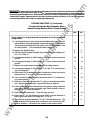
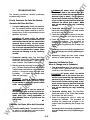
P REVENTIVE MAINT ENA NCE
Performing the yearly preventive maintenance procedures in Table 1-1 will result in operational reliability of
the transfer switch.
ua
ls
I AwARNING I AC power within the cabinet and the rear side of the cabinet door presents a shock hazard
that can cause severe persona/ Injury or death. In addition, Incorrect Installation, service, or parts
replacement can result In severe personal injury, death, and/or equipment damage. Therefore, all cor
rective service procedures must only be performed by technically qualified personnel, following the
procedures provided In this manual.
IAwARNINGl The transfer switch presents a shock hazard that can cause severe persona/ Injury or
death unless all AC power Is removed. Be sure to move the generator set operation selector switch to
Stop, disconnect AC line power, disconnect the banery charger from its AC power source, and dis
connect the starting banery (negative [-] lead first) before servicing.
an
IAWARNINGllgnltlon of explosive banery gases can cause severe personal injury. Do not smoke or
cause any spark, arc, or flame while servicing baUerles.
TABLE 1-1. ANNUAL PREVENTIVE MAINTENANCE
tM
1. DISCONNECT ALL SOURCES OF AC POWER :
ar
lP
.E
4.
lec
tri
3.
ca
2.
Disconnect both AC power sources from the transfer switch before continuing. I f a generator set pro
vides Emergency power, turn the operation selector switch to Stop. (The selector switch is located on
the generator set control panel.} If there Is an external baUery charger, disconnect It from its AC
power source. Then disconnect the set starting battery (negative (-] lead first}.
CLEAN
a. Thoroughly dust and vacuum all controls, meters, switching mechanism components, interior
buswork, and connecting lugs .
b. Close the cabinet door and wash exterior surfaces with a damp sponge (mild detergent and
water}. Do not allow water to enter the cabinet, especially at meters, lamps, and switches.
I NSPECT
a. Check buswork and supporting hardware for carbon tracking, cracks, corrosion, or any other
types of deterioration. If replacement is necessary, call your dealer or distributor.
b. Check stationary and movable contacts. If contact replacement is necessary, the procedures
are described in section 4 of this manual.
c. Check system hardware for loose connections. Tighten as indicated in step 4.
d. Check all control wiri ng and power cables (especially wiring between or near hinged door} for
s igns of wear or deterioration.
e. Check all control wiring and power cables for loose connections. Tighten as indicated in step 4.
f. Check the cabinet interior for loose hardware. Tighten as indicated in step 4.
PERFORM ROUTINE MAINTENANCE
a. Tighten buswork, control wiring, power cables, and system hardware, as necessary. Hardware
torque values are given in section 4 of this manual. Retorque all cable lug connections. Lug
torque requirements are listed in Table 1-2.
b. Service or replace the batteries.
CONNECT AC POWER AND CHECK OPERATION
a. Connect the set starting battery (negative [ -] lead last). Connect the normal AC power source,
enable the backup power source. If applicable, connect power to the battery charger.
b. Verify proper operation of the battery charger.
c. Test system operation as described in this section. Close and lock the cabinet door.
ww
w
5.
1-Q
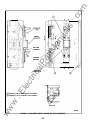
SET SCREW
SOCKET SIZE
(ACROSS FLATS)
I AWARNING I AC power within the cabinet and the
rear side of the cabinet door presents a shock
hazard that can cause severe perscmal lnjury or
death. Disconnect connector J1/P1 before
working on the electronic control .system.
MINIMUM TORQUE
FOR PROPER
OPERATION
80 IN-L.BS (9 N•m)
200 IN-L.BS (23 N•m)
2751N-L.BS (31 N•m)
3751N-L.BS (43 N•m)
500 IN-L.BS (57 N•m)
600 IN-L.BS (68 N•m)
ua
ls
3/16 1N
1/41N
5/161N
3/BIN
1/21N
9/161N
Disconnecting J1 /P1 removes all power to the
door except for customer-Introduced power at
the Signal Module. Be sure to remove all power
before replacing components.
an
No special tools are req uired to remove and re
place control system components.
w
.E
lec
tri
ca
lP
ar
tM
The mother board and transformer assembly are
held in place by several screws and will not fall
when the four screws that secure the Power Sentry
cover are removed . Be sure to use all of the hard
ware w hen remounting components.
ww
.c
om
TABLE 1-2. LUG TIGHTENING
REQUIREMENTS
REMOVING AND REPLACING
ELECTRONIC
CONTROL COMPONENTS
1 -1 0
FEATURE
DESCRIPTION
Poles
Battery Chargers
3 Poles . . . . . . . . . . . . . . . . . . . . . . . A028
4 Poles . . . . . . . . . . . . . . . . . . . . . . . A029
.
.
.
.
.
.
.
.
.
.
.
.
.
.
.
.
.
.
.
.
.
.
.
.
.
.
.
.
.
.
.
.
.
.
.
.
ua
ls
Battery Charger - 1 OA,24V . . . . . . . K003
Appl - Utility to Genset .
Appl - Utility to Utility . . .
Appl - Genset to Genset
Appl - Nonautomatic . . .
A035
A036
A037
A038
Auxiliary Relays
Aux Relay - 24 VAC Coil . . . . . . . . . L001
Aux Relay - Emergency Position . . . L002
Aux Relay - Normal Position . . . . . . L003
Agency Approvals
an
Aux Relay - Emergency Source . . . L004
Usting - UL . . . . . . . . . . . . . . . . . . . A046
Certification - CSA . . . . . . . . . . . . . . A047
U sting - Not Applicable . . . . . . . . . . A048
Aux Relay - Nonnal Source . . . . . . . L005
Aux Relay - 24 VDC Coil . . . . . . . . . L1 01
Aux Relay - Emergency Position . . . L1 02
tM
Frequency
Aux Relay - Normal Position . . . . . . L1 03
Aux Relay - Genset Start . . . . . . . . . L1 04
Hertz . . . . . . . . . . . . . . . . . . . . . . A044
Hertz . . . . . . . . . . . . . . . . . . . . . . A045
Aux Relay - 1 2 VDC Coil . . . . . . . . . L201
ar
50
Voltage
Aux Relay - Emergency Position . . . L202
Aux Relay - Normal Position . . . . . . L203
ca
lP
1 20 VAC . . . . . . . . . . . . . . . . . . . . . . R020
208 VAC . . . . . . . . . . . . . . . . . . . . . . R021
R022
220 VAC
R023
240 VAC
R024
380 VAC
R025
41 6 VAC
R026
480 VAC
R027
600 VAC
Miscellaneous
Clock - 7 Day Exerciser . . . . . . . . . J001
Module - 3-Wire Start . . . . . . . . . . . M002
Tenninal Block - 30 Points . . . . . . . . M003
Monitor - Phase Seq/Bal . . . . . . . . . M004
Sequencer - Stdby Set Start, 1 2V . . MOOG
Load Shed - F rom Emergency . . . . M007
.E
lec
System - 1 Phase, 2-W or 3-W . . . . A041
System - 3 Phase, 3-W or 4-W . . . . A042
Module - Alarm . . . . . . . . . . . . . .
Sequencer - Stdby Set Start, 24V
Switch - Auto/Manual Change . . .
Tenn Block - Batt Chrg Alanns . .
Control Options
Start Time Delay - 90 Sec . . . . . . . . C01 5
Control - OV & 0/U Hz,Source 2
C01 6
C01 7
Control - OV & 0/U Hz,Source 1
Meters
Meters - None . . . . . . . . . . . . . . . . . D001
Meters - Door Mounted . . . . . . . . . . D002
.
.
.
.
.
.
.
.
MOOS
M01 0
N001
N002
Tenn Block - Source1 /2 Rmt Signal
N005
Power Connect - Bus Stabs
N009
w
Cabinet
Cabinet - Type 1 . . . . . . . . . . . . . . . 8001
Program Transition
ww
Aux Relay - Genset Start . . . . . . . . . L204
Module - Signal . . . . . . . . . . . . . . . . M001
tri
Phase
FEATURE
OPTION
Battery Charger - 2A, 1 2/24V . . . . . . K001
Battery Charger - 1 OA, 1 2V . . . . . . . K002
Application
60
.c
om
FEATURE
OPTION
FEATURE
DESCRIPTION
Cabinet - Type 3R . . . . . . . . . . . . . . B002
Cabinet - Type 4 . . . . . . . . . . . . . . . 8003
J02 1
Program Transition - o -7.5 Sec
Program Transition o-60 Sec . . . . J022
Open Construction . . . . . . . . . . . . . . 8004
-
1 -1 1
w
ww
.E
tri
lec
an
tM
ar
lP
ca
ua
ls
.c
om
INTRODUCTION
.c
om
2. Electronic Control System
cal. Each transformer assembly must be used with
the correct line voltage and phase or the control can
be damaged when power is applied. For this rea
son, the transformer assemblies from different con
trols are not necessari ly interchangeable.
The electronic control system includes:
ua
ls
1 . The voltage sensing and start, stop, transfer,
and retransfer timing circuitry of the Power
Sentry control.
When replacing a transformer assembly, note that
the transformer input leads are wired with a line-to
line or line-to-neutral configuration, and with jumper
wires across some of the TB1 1 terminals. The wir
ing and jumper wire configurations are voltage and
phase dependent. Refer to sheet 3 of 5 in your
schematic and wiring diagram package.
2. The transformers, relays, switch, and connec
tors of the accessory control panel.
an
3. The optional control modules and accessories.
4. The position-sensing switches that monitor
and control the operation of the automatic
transfer switch.
Mother Board Assembly
tM
5. The standard and optional lamps, meters, and
switches that are mounted on the cabinet door.
These components are described i n Section 1 .
They are also referenced in this section, when
applicable.
ar
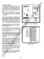
POWER SENTRY CONTROL
•
•
ca
•
Transformer assembly
Mother board
Voltage sensor modules
Time delay module
lP
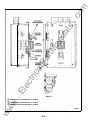
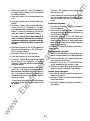
The Power Sentry control {Figure 2-1 ) consists of
the following major components:
•
tri
All components of the Power Sentry control are
mounted within a single enclosure.
The timing, sensitivity, and calibration potentiome
ters and LED control lamps are visible and accessi
ble through holes on the control cover {Figure 2-1 ).
There are three different mother boards. Utility-to
generator set transfer switches may be equipped
with mother board 300-3953 or mother board
300-3090. Utility-to-utility and generator set-to
generator set transfer switches are equipped with
mother board 300-3267.
.E
lec
Mother board Identification: Mother board
300-3090 has one With/Without Load switch.
Mother board 300-3953 has two With/Without Load
switches. Mother board 300-3267 does not have a
With/Without Load switch.
The following text provides a general description of
each component and how it functions.
The schematics of the various mother boards ap
pear in Section a. Significant differences are
pointed out In this section.
Transformer Assembly
The transformer assembly is mounted in the control
as shown in Figure 2-1 . The assembly i ncludes
four transformers, a terminal block, and a ribbon
cable connector. The transformers step down the
line voltage to approximately 1 8 VAC. The output
from the transformers is supplied to the mother
board rectifier bridges.
J1, J2, and J3 Edge Connectors: Connectors J 1
and J 3 provide a mechanicaVelectrical connection
point for the voltage sensor modules. Connector J 1
corresponds to the Source 1 {Normal) power
source and J3 corresponds to the Source 2 {Emer
gency) power source. Connector J2 provides a me
chanicaVelectrical connection point for the time de
lay module.
w
ww
The mother board assembly is a printed circuit
board that serves as a central terminal for all the i n
put and output signals that flow through the control.
It also provides a mounting point for the voltage
sensing and time delay modules and several con
trol relays, including K1 1 , the two-wire run relay.
Connections to the mother board are made through
five mating/locking pin connectors {J4, J5, J6, J7,
and J8) and three circuit board edge connectors
{J 1 , J2, and J3).
The transformer assemblies are not the same for
every control, even though they may appear identi2-1
�
c:=
1:11
CJDCJDDDDDDD
......
Cl
1:11
El
1:11
'"'
0
•
c::::J :
TIME DELAY
MODULE
.
1:11 •
c::::J '
PHASE
SELECTOR
SWITCH S2
Cl
1:11
1:11
1:11
1:11
1:11
1:11
1:11
ar
0
1:11
PHASE
SELECTOR
SWITCH S3
0
0
tri
The schematic of the 300-3953
mother board is on page 8-3.
The schematic of the 300-3267
mother board is on page 8-4.
The schematic of the 300-3090
mother board is on page 8-5.
.E
w
ww
0\
ES16984c
PowerSentry_
lec
0
ca
lP
TRANSFORMER
ASSEMBLY
0
Cl
tM
c::::J
1:11
EMERGENCY
VOLTAGE SENSOR
MODULE
an
NORMAL
VOLTAGE
SENSOR
MODULE
0
ua
ls
LOCAL TEST
WITH/WITHOUT
LOAD SELECTOR
SWITCH
0
.c
om
30Q-3953 MOTHER BOARD
EXERCISE
WITH/WITHOUT
LOAD SELECTOR
SWITCH
CONTROL
COVER
0
e1ao
AGURE 2-1. POWER SENTRY CONTROL
2-2
.c
om
Mother Board Circuitry: The mother board cir
cuitry serves several functions that are essential for
control operation.
The Transfer Inhibit input, when open, prevents
Emergency power from being sensed. This input is
at terminals 5 and 6 of TB2.
A series of rectifier bridges receive the AC output
from the transformer assembly (connector J6) and
rectify it. The rectified voltage (1 5 to 25 VDC) is
used as a reference input for the voltage sensors
and as a power source for the control electronics.
The circuitry for the rectifier bridges is shown in the
schematics in Section 8.
The Instant Retransfer input {from the Test/Normal/
Retransfer switch) is optically coupled to the time
delay module to override the retransfer time delay.
ua
ls
On all versions of the mother board, the transfer
and retransfer inputs are used in conjunction with
the optional signal module relay board. Refer to
Optional Control Modules in this section.
Separate voltage regulator circuits receive the out
put from the Normal and Emergency side rectifier
bridges and regulate the voltages to a constant
value (12 ±0.5 VDC). These circuits provide power
for the control relays, display lamps, voltage sensor
modules, and time delay module.
an
Utility-to-utility and generator set-to-generator set
mother boards include Source 1 and Source 2 se
lect inputs. These inputs are wired to the Source
Selector switch on the cabinet door. Refer to sec
tion 5 or 6.
Generator set-to-generator set mother boards may
include an optional change-over clock input Refer
to section 5.
tM
Capacitor C1 is large enough (0. 1 or 0.47 farads) to
provide power to the time delay module from the
time Normal power is lost until Emergency power is
available. Refer to Control System Operation.
ar
Switches: There are three switches on the
300-3090 mother board and four switches on the
300-3953 mother board.
Additional Inputs to the utility-to-generator set
mother board Include:
•
•
•
lP
•
Test/exercise inputs
Manual retransfer input
Transfer inhibit input
Instant retransfer input
(Delayed) transfer and retransfer inputs
ca
•
The test/exercise inputs (from the Test/Normal/
Retransfer switch and from the optional exerciser
clock) are used to start the generator set. Their
function is described under Control System Opera
tion in this section.
.E
lec
tri
On the 300-3953 mother board, Switch S1 is the
Exercise With/Without Load selector. When this
switch is in the With Load position, the exercise
function includes the transfer of load to the Emer
gency side. When S1 is in the Without Load posi
tion, the exercise function starts and runs the gen
erator set, but does not transfer the load.
Closure of a set of contacts across the remote test
transfer inputs (terminals 7 and 8 of TB2) causes
the transfer switch to sense a (simulated) utility
power failure and send a start/run signal to the gen
erator set. The load is transferred to the generator
set when generator set power becomes available.
On the 300-3953 mother board, there is a Switch
S4. S4 is the Test With/Without Load selector.
When this switch is in the With Load position, the
local test function (using the Test switch on the
cabinet door) includes the transfer of load to the
Emergency side. When S4 is in the Without Load
position, the test function starts and runs the gen
erator set, but does not transfer the load.
w
On 300-3090 mother boards, the With/Without Load
swnch must be In the WHh Load position. On
300-3953 mother boards, this Input Is NOT depend
ent upon the position of With/Without Load switch.
ww
On the 300-3090 mother board, Switch S1 is the
With/Without Load selector. When the switch is in
the With Load position, test and exercise functions
include the transfer of load to the Emergency side.
When S1 is in the Without Load position, test and
exercise fu nctions start and run the generator set,
but do not transfer the load.
The With/Without Load swltch(es) Is (are) Included
only on the utility-to-generator set transfer switch.
The manual retransfer input (from the optional
Auto/Manual switch) blocks automatic retransfer
and permits only manually initiated retransfer.
Switches S2 and S3 are used to select single- or
three-phase operation.
2-3
.c
om
Relays: There are six relays on thH 300-3090
mother board and eight relays on thE� 300-3953
mother board. Three are used to send primary con
trol signals, and the others are used to c:ontrol logic
functions on the mother board itself.
retransfer relay. K1 and K2 are located on the ac
cessory control panel.
The K1 6 run interlock relay is energized whenever
the transfer switch is in the Emergency position.
When energized, its contacts 2 and 4 are open.
This functions to prevent generator shut off until
retransfer to the Normal side occurs.
Relays K1 0 and K1 8 are included only on the
300-3953 mother board. These two relays are criti
cal to the operation of with load test and exercise.
Refer to Control System Operation.
The K1 1 two-wire run relay responds to a signal
from the time delay module. When this normally
energized relay is de-energized, K1 1 contacts 3
and 2 close to send a two-wire start si9nat. Note:
Output connections for two-wire starting are made
at TB2 on the transfer switch assembly.
ua
ls
There are two run Interlock relays on the generator
set-to-generator set mother board.
Additional outputs from the mother board include:
Start Genset outputs
•
Source 1 and 2 Avai lable outputs
•
Transfer and Retransfer outputs
•
Backup Source Failure outputs
Start Genset and Source 2 Available outputs are
available for connection to the optionai 3-Wire Start
module.
an
•
tM
There are 2 two-wire start relays on the generator
set-to-generator set mother board.
The K1 2 source 2 available relay is ene�rgized only
when the source 2 sensor determines that Emer
gency power is acceptabte. The opening of K12
contacts 4 and 2 (in conjunction with t�est or exer
cise with load signals) helps simulate a loss of Nor
mal power for test and exercise purpos43S. If Emer
gency power fails during a test or exercise, the clos
ing of these contacts initiates retransfer to the Nor
mal power source.
ar
The g�nerator set-to-generator set mother board
includes a Start Genset 1 output and a Start Genset
2 output. These two outputs, as well as Source 1
and Source 2 Available outputs, are available for
connection to the (two) optional 3-Wire Start mod
ules.
lP
Start Genset, Source 1 Available, Source 2 Avail
able, Transfer, Retransfer, and Backup Source
Failure outputs are avai lable for connection to the
optional Signal Module relay board.
ca
The K12 relay Is Included only on the u1tlllty-to-gen
erator set mother board.
lec
tri
On the 300-3090 mother board, the K1 3 test/exer
cise relay is energized by a signal at one of the test/
exercise inputs. When K1 3 is energized, its con
tacts 3 and 2 open. This action de-ene!rgizes K1 1 ,
starting the generator set.
.E
On the 300-3953 mother board, the K1 3 test/exer
cise relay is energized by a signal at om� of the test/
exercise inputs only when the corresponding With/
Without Load switch is in the Without Load position.
When K1 3 is energized, its contacts 3 and 2 open.
This action de-energizes K1 1 , starting the genera
tor set.
The K13 relay Is Included only on the u1tlllty-to-gen
erator set mother board.
The voltage sensors are plug-in modules that fit
into the J1 and J3 edge connectors on the mother
board. The voltage sensors monitor the voltage
sources (single or three phase) and provide an out
put signal (Source Available) when the source is
within predetermi ned limits. Depending on the op
tions selected, the sensors test for undervoltage,
overvoltage and under/overfrequency. The Source
Available output signal is latched on when all of the
pickup requirements for voltage and frequency are
satisfied. The Source Available output signal re
mains on until the voltage or frequency goes be
yond the dropout limits for longer than the corre
sponding dropout time delay.
w
Undervoltage sensing is accomplished by sensing
all voltage phases, but responding only to the low
est one. Thus, all phases must be above the under
voltage pick-up point before undervoltage pickup
will occur; while undervoltage dropout will occur
when any of the phase voltages fall below the drop-
The K1 4 and K1 5 transfer and retransfHr relays are
energized by signals from the time delay module.
When energized, their contacts 3 ancl 4 close to
provide power to one of the interposing relays. K 1 4
drives the K2 transfer relay. K1 5 driiv es the K1
ww
Voltage Sensor Modules
2-4
.c
om
returns during the timing out period, the timer is re
set. If the signal does not return by the end of the
delay period, the timer signals for the generator set
to start. The purpose of this delay is to prevent gen
erator set start-up when power interruptions of very
short duration occur. An optional time delay mod
ule, with a 0 to 90 second start time delay range, is
also available.
ua
ls
out point. A fixed dropout time delay (0.5 seconds}
elapses before the Source Available output re
sponds to an undervoltage condition. The sensor is
calibrated and the undervoltage pickup and drop
out points are adjusted with potentiometers (refer
to Adjusting Power Sentry Modules in this section).
The pickup adjustment range is 85% to 1 00% of the
nominal voltage. The dropout adjustment range is
75% to 98% of the pickup setting.
The utility-to-utility transfer switch has no start time
delay.
Overvoltage sensing is accomplished by monitor
ing the peak of the combined phase voltages so
that the sensor essentially responds to the highest
phase. The sensor is calibrated and the overvolt
age limit is adjusted with potentiometers (refer to
Adjusting Power Sentry Modules in this section).
The overvoltage adjustment range is 1 05% to
1 35% of the nominal voltage. The pickup point is
fixed at 5% below the overvoltage limit point and is
not adjustable. A time delay is also included and is
adjustable from 0 to 120 seconds.
an
The transfer time delay, adjustable from 0 to 1 20
seconds, begins timing as soon as the Source 2
voltage sensor signals that power is available. At
the end ofthe delay, the timer signals for the load to
transfer to the generator set. The purpose of the
delay is to allow the generator set to stabilize before
the load is applied.
tM
When the Source 1 power returns and Source
Available signals are received from both voltage
sensors, the time delay module will respond to the
preferred source. In utility-to-generator installa
tions, Source 1 is recognized as the preferred
source. I n utility-to-utility or generator-to-generator
installations, the preferred source is selected by
setting an externally mounted selector switch.
tri
Time Delay Module
ca
lP
ar
Over/underfrequency sensing is accomplished by
sensing the source frequency and detecting when it
is within a specific band. The pickup bandwidth is
adjusted with a potentiometer (refer to Adjusting
Power Sentry Modules i n this section). The pickup
adjustment range is 5% to 20% of the nominal fre
quency. The dropout bandwidth is fixed at 5%
wider than the pickup band. The pickup and drop
out bands are centered about the nominal fre
quency. A time delay is also included and is adjust
able from 0 to 1 5 seconds.
The time delay module plugs into the J2 edge con
nector on the mother board. The time delay module
contains the timing circuits and associated logic
that provide time delays for generator starting, load
transfer, load retransfer, and generator stopping.
.E
lec
The stop time delay, adjustable from 0 to 1 0 min
utes, begins timing as soon as the retransfer timer
signals for the load to transfer to the normal source.
At the end of the delay, the timer signals for the gen
erator set to stop. The purpose of the delay is to
allow the generator set to cool while running at no
load.
The Source Available output signals are received
from the voltage sensors. If the Source 1 Available
signal is interrupted, the start time delay begins tim
ing out.
On the utility-to-utility transfer switch, stop time de
lay Is not applicable.
The start time delay, adjustable from 0 to 1 5 sec
onds, begins timing if the input signal from the
Source 1 voltage sensor is interrupted. If the signal
Refer to Adjusting Power Sentry Modules in this
section for the time delay adjustment procedures.
w
ww
The retransfer time delay, adjustable from 0 to 30
minutes, begins timing as soon as the input signal
from Source 1 voltage sensor is sent to the time de
lay module. At the end of the delay, the timer sig
nals for the load to transfer to the normal source.
The purpose of the delay is to allow the normal
power source to stabilize before the load is applied.
2-5
Mounted at the edges of the voltage sensor and
time delay modules, and visible through holes in
the Power Sentry cover, are eight indicator lamps.
Refer to Table 2-1 .
TABLE 2-1 . POWER SENTRY CONTROL INDICATOR LAMPS
LAMP
.c
om
Indicator Lamps
ua
ls
INDICATES
Source 1 voltage is available and within the voltage and frequency settings of the
voltage/frequency sensor.
Source 2 Available
Source 2 voltage is available and within the voltage and frequency settings of the
voltage/frequency sensor.
Start Gen Set
The control is signaling the generator set to run. This lamp is dimly lit (or off) when
both sources are off.
(Stop) Timing
The control is timing out the generator stop delay. At the end of this delay, a stop signal
is sent to the generator set and the Start Gen Set and (Stop) Timing lamps go out.
(Retransfer) Timing
Control is timing out for retransfer to Source 1 power. At the end of the timing period,
the lamp goes out and the Retransfer Complete lamp turns on.
(Retransfer) Complete
Control is signaling for retransfer to Source 1 power. The Source 1 Available lamp is
also on.
(Transfer) Timing
Control is timing out for transfer to Source 2 power. At the end of the timing period,
the lamp goes out and the Transfer Complete lamp turns on.
(Transfer) Complete
Control is signaling for retransfer to Source 2 power. The Source 2 Available lamp is
also on.
ww
w
.E
lec
tri
ca
lP
ar
tM
an
Source 1 Available
2-6
.c
om
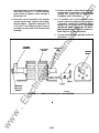
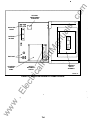
ACCESSORY CONTROL PANEL
AND TERMINAL BLOCKS
Relays
Interposing relays K1 and K2 are used to transfer
line power to the linear actuator motor (M1 ). The
closing of K1 contacts causes retransfer to the Nor
mal side. The closing of K2 contacts causes trans
fer to the Emergency side. K1 is energized by the
closing of K1 5 contacts. K2 is energized by the
closing of K1 4 contacts. (K1 5 and K 1 4 are on the
mother board.) Refer to sheets 2, 4, and 5 of your
schematic and wiring diagram package.
ua
ls
The accessory control panel (Figure 2-2) includes:
•
T1 and T2 transformers
•
T3 optional transformer
•
K1 and K2 interposing relays
•
K3 and K4 optional relays
•
Motor Disconnect Switch 51
•
Connectors J1 , J2, and J3
•
TB4 terminal block
Not included on the accessory control panel, but re
lated in function, are terminal blocks TB1 , TB2, and
TB3 (Figure 2-3).
an
Optional programmed transition relay K3 is used to
open the circuit that drives the linear actuator motor
(M1 ) for a time determined by the setting of the Pro
gram Transition module. Refer to sheets 2 and 5 of
your schematic and wiring diagram package, and
to Optional Control Modules and Accessories in
this section.
Transformers
Transformers T1 and T2 provide 24 VAC power for
the cabinet door display lamps; relays K1 , K2, and
K16; and the optional exerciser clock. (K1 6 is on
the mother board.) Refer to sheets 2, 3, and 4 in
your schematic and wiring diagram package.
Transformer T3 is used with the optional voltage
and frequency meters on units that are rated at
more than 300 volts. Refer to sheets 2 and 5 in your
schematic and wiring diagram package.
ar
tM
Optional load shed relay K4 (not shown) is driven
by a customer-supplied signal and is used to drive
the linear actuator motor (M1 ) from the emergency
position to the neutral position. Refer to sheets 1 , 2,
and 5 of your schematic and wiring diagram pack
age, and to Optional Control Modules and Acces
lP
sories.
tri
ca
0
GND
0
ww
w
.E
lec
T1
0
(9
0
K1
0
0
D
J2
0
~
J30
0
K3
&
J1
0
0
0
0
0
0
0
�
FIGURE 2-2. ACCESSORY CONTROL PANEL
2-7
�
0
ES1681·1
.c
om
Motor Disconnect Switch 51
options. Refer to sheet 1 of your schematic and wir
ing diagram package, and to Optional Control Mod
ules and Accessories.
Motor Disconnect Switch S1 is used to disable the
linear actuator motor. In the Off position, the switch
is open. In the Auto position, the switch is closed.
Refer to sheets 2 and 4 of your schematic and wir
ing diagram package.
Open Construction
On open construction configurations, indicator
lamps and key switches are connected to TB3. Re
fer to sheet 1 of your schematic and wiring diagram
package and to the Open Construction Wiring Dia
grams sheet in Section 8.
Connectors
ua
ls
Accessory control panel connectors J 1 , J2, and J3
are used to connect the electronic control system to
the power terminals, auxiliary switch contacts, lin
ear motor, and the terminals of TB2. Disconnecting
J 1 disconnects all line power from the door. Refer
to sheets 2 and 4 in your schematic and wiring dia
gram package.
OPTIONAL CONTROL MODULES
AND ACCESSORIES
an
Optional Control Modules include:
•
3-Wire Start
•
Program Transition
•
Signal Module
•
Exerciser clock (utility-to-generator set trans
fer switch)
•
Change-over clock (generator set-to-genera
tor set transfer switch)
•
Phase Sequence/Balance Monitor
•
Standby Set Start Sequencer (generator set
to-generator set transfer switch)
Optional accessories include:
•
Battery charger
•
Auxiliary relays
•
Load Shed function
•
Meter package
•
Auto/Manual switch
•
600 Volt adapter transformer T4
Terminal Blocks
lP
ar
tM
Terminal block TB4 provides six AC connection ter
minals. Refer to sheets 2, 4, and 5 of your sche
matic and wiring diagram package.
Terminal block TB1 (Figure 2-3) provides the con
nection terminals for form C auxiliary switch con
tacts. Refer to sheet 1 of your schematic: and wiring
diagrams package.
Terminal block TB2 (on the utility-to-generator
transfer switch) provides the connection terminals
for two-wire start, transfer inhibit and n�mote test.
Refer to sheet 1 of your schematic and wiring dia
gram package.
ca
Refer to section 5, 6, or 7 If applicable.
Terminal block TB3 (Figure 2-3) provid1�s the con
nection terminals for the 3-Wire Start, Load Shed,
lec
tri
battery charger alarm contacts, and Signal Module
------
r-., �
i�
I
i
r
r
�
�
�
ww
Alarm Module
TB1
r
r
F
r
'
r '
r r
( (
r (
CAUTION
�7;.-�
...:..
.::::
w
.E
TB3
:
len
•
- ---
TB2
ES-1688
FIC:iURE 2-3. TERMINAL BLOCKS
2-8
®
F
10
©
tM
Shuts down the generator set and
prevents it from starting. Use this
position when servicing the gen
erator set.
ca
tri
lec
Handcrank: Prevents the automatic
transfer
switch from starting the generator set,
but allows starting and stopping at the
set. Use this position for generator
set maintenance.
.E
Connections for the optional 3-Wire Start module
are made at TB3.
Generator set-to-generator set transfer switches
can be equipped with two 3-Wire Start modules. Re
fer to section 5.
ww
w
Refer to sheets 1 and 5 of your schematic and wir
ing diagram package.
CD
s:
Ill
..
D.
�
r::
Cll
..
u
..
Overcrank
Raaat
®
3 Wire Start
ii
an
®
ar
Stop:
lP
Allows the generator set to start and
assume the load if a power outage oc
curs. This Is the normal operating
position.
Stop
1
The Auto/Handcrank/Stop switch has three posi
tions that function as follows:
Auto:
Handcrank
J1 1
If used, the preheat timer delays the start signal (0
to 60 seconds} while a preheat output is energized.
The Preheat Timing lamp is on during this delay.
The overcrank timer limits the time the engine
starter motor is engaged. If the generator set does
not start within the adjustable time limit (0 to 1 20
seconds), a relay opens the starting circuit. During
cranking the Overcrank Timing lamp is on. If the
overcrank timer opens the circuit, a Lockout lamp is
lit. After a starting problem is corrected, press the
Overcrank Reset switch to reset the timer. It cannot
be reset by any other method.
@
Auto
Ill
>
0
1/:r
Timing
Off l = l an
Delay
(Saconda)
ua
ls
The 3-Wire Start module (Figure 2-4} provides
start/stop signals and a preheat signal for a three
wire start system. It includes a preheat timer, an
overcrank timer, an overcrank reset switch, an
Auto/Handcrank/Stop switch, and three indicator
lamps. The 3-Wire Start module may be equipped
with a preheat timer On-Off switch.
.c
om
Three-Wire Start
0
Delay
II
e
eo
�
Timing
(Saconda)
e
0
Lockout
II
1 20
e
FIGURE 2-4. 3-WIRE START
®
SC1 57�a
®
Timing
ay
��:lDelayay �Del(Second
a)
J30
1
Program
Transition
®
SC1583
tM
FIGURE 2-5. PROGRAM TRANSITION MODULE
lP
ca
tri
lec
.E
w
ww
so
an
®
e
0
®
ua
ls
�
ar
The optional Program Transition module (Figure
2-5) is used to introduce a pause during transition.
Programmed transition allows the transfer switch to
assume a midtransition position for an adjustable
interval of time. In this position, the load is not con
nected to either (Normal or EmergEmcy) power
source. This feature allows residual voltage from
inductive loads to decay to an acceptable level be
fore transfer is completed.
The length of time that the transfer switch is i n the
midposition can be adjusted from 0 to 7.5 seconds
or 0 to 60 seconds, depending on the timer option.
The proper adjustment is a function of the load de
cay time.
A Delay/No Delay switch permits bypassing the
timer delay (if it is not needed or if the timer has
failed).
The timing circuit is triggered by the same signal
that is used to drive K1 or K2. The output of the tim
ing circuit is u sed to energize K3. Contacts
K3-6/K3-9 and contacts K3-4/K3-7, acting in con
junction with auxiliary switches S9 and S5 respec
tively, control the linear actuator circuit. When the
normally open contacts of K3 close, the linear ac
tuator circuit is completed and the switch contacts
are moved from the neutral position to their original
destination.
Refer to sheets 2 and 5 of your schematic and wir
ing diagram package.
.c
om
Programmed Transition
2-1 0
The optional Signal Module (Figure 2-6) has one
adjustable timer. The Elevator Signal delay con
trols the timing of two events. It delays transfer/
retransfer and energizes the Elevator Transfer Sig
nal relay during the delay period. This time delay is
adjustable over a range of 0 to 50 seconds.
A Delay/No Delay switch permits bypassing the
timer delay (if it is not needed).
The timing circuit is started by a transfer or a
retransfer signal from the time delay module on the
Power Sentry mother board.
If the transfer switch includes the Signal Module, re
sistors R 1 0 and R1 1 on the mother board (sche
matic i n section 8) are removed. Because these re
sistors are removed, the transfer and retransfer sig
nals from the time delay module do not have a di
rect path to relays K1 4 and K1 5. I nstead, these sig
nals are directed to the Signal Module and are re
turned to drive the relays after the elevator time de
lay has elapsed.
While the timer is timing, the {form C) Elevator Sig
nal relay is energized and the Timing lamp on the
Signal Module is lit. At the end of the ti me delay, the
Elevator Signal relay is de-energized and the
switch is allowed to transfer.
�!;!}
®
1--r=='
16
ua
ls
"i
0
1
®
Signal Module
1£.
en
T iming
Qj Delay
'
an
r--=®
Ui
( S e conds)
•
�
0
!>0
tM
ar
lP
ca
tri
lec
.E
w
Refer to section 5 or 6 for a description of generator
set-to-generator set or utility-to-utility signal mod
ules.
All relay contact connections are made at TB3. Re
fer to sheet 1 of your schematic and wiring diagram
package.
2-1 1
®
SC1584
RGURE 2-6. SIGNAL MODULE
Source 1 Available
•
Source 2 Available
•
Test/Exercise
•
Backup Source Available
These relays are not affected by the Elevator Signal
delay. They respond directly to signals from the
Power Sentry.
The Source 1 and Source 2 Available relays are en
ergized whenever their respective power sources
are producing power.
I n utility-to-generator set applications, the Source 2
Available and Backup Source Available relays op
erate identically.
The Test/Exercise relay is energized whenever the
system is in test or exercise mode.
ww
D e lay
J2 1
When i nstalled on a utility-to-generator set transfer
switch, there are four other Signal Module relays
with form-e contacts:
•
No
Delay
.c
om
Sig nal Module
0
The optional exerciser clock (Figure 2-7) initiates
generator set start/run cycles at programmable in
tervals and for programmable durations. It is a
7-day, 24-hour clock that can store and execute up
to ten start/stop programs (exercise cycles).
n-nn
U·UU
(�
� 1/0iijii
ua
ls
El
I
Cll[) t
an
justing Optional Control Modules.
0
ar
The Exercise With/Without Load switch provides
the option of transferring or not transferring the load
during the exercise periods.
tM
FIGURE 2-7. EXERCISER CLOCK
The output of the exerciser clock is a set of normally
open contacts that, when closed, provide a ground
to the Power Sentry mother board (schematic in
section 8) input J7-8. This signal energizes test/ex
ercise relay K1 3 on the mother board ..
tri
ca
lP
The three-position switch in the lower lleft corner of
the clock can be used to override the program. To
test the exercise function (close the output con
tacts), place the switch in the "I" position. To dis
able the exercise function (hold the output contacts
in the open position), place the switch i n the "Off"
position. For normal operation (output contacts un
der program control), place the switch in the center
(clock) position.
lec
The exerciser clock is powered by the 24 VAC out
put of T1 . An internal nickel cadmium battery (not
replaceable) maintains time and program i nforma
tion for 1 50 hours (minimum) without external
power. However, the clock does not iinitiate exer
cise periods when it is under battery power.
.E
0
OfiE)
Programming the exerciser clock requires setting
the time of day and entering the exercise start and
stop times. This procedure is describEK1 under Ad
Refer to sheets 2 and 5 of your schematic and wir
ing diagram package.
w
n-nn
U·UU
1 2 3 4 5 1 7
Instead of an exerciser clock, generatc•r set-to-gen
erator set transfer switches may Include an optional
change-over clock. Refer to section 5 If applicable.
ww
I
.c
om
Exerciser Clock
SC157ll
.c
om
Phase Sequence/Balance Monitor
The optional phase sequence/balance monitor
{Figure 2-8) is connected to A, B, and C phases of
utility power. If there is an over- or undervoltage, a
phase reversal, a loss of one phase, or an unbal
anced voltage condition; a normally energized re
lay drops out, closing a set of contacts. These relay
contacts are wired to the remote test input terminals
{7 and 8) of TB2. When the contacts across termi
nals 7 and 8 of TB2 close, the generator set start/
transfer of load sequence is initiated.
Five LEOs indicate normal operation or fault condi
tions. The Relay Energized LED is lit during normal
operation. Three potentiometers permit setting the
percent of voltage unbalance, the normal system
voltage, and the relay dropout time delay.
�
an
0.
2
•
tM
ar
Overvoltage dropout occurs at normal voltage
+ 1 0% (±2%).
Undervoltage dropout occurs at normal volt
age -1 0% (±2%).
Dropout time delay range is 2 to 20 seconds.
Percent voltage unbalance range is 2 to 6% on
240- and 480-volt units.
Percent voltage unbalance range is 2 to 8% on
380-volt units.
0
tri
2
3
lec
4
5
6
.E
7
8
9
w
II
0
TO TB2,
IIEWIIM..
e
OllER
-..rME
21rs2RO 50. 11
-
200
1140
-'WLTME
7&8
10
2
110
TDE I:IELAY
Dl -
3074801e
FIGURE 2-8. PHASE SEQUENCE
BALANCE MONITOR
TBI
Standby Set Start Sequencer
The optional standby set start sequencer (Figure
2-9) is available {and applicable) only on a genera
tor set-to-generator set transfer switch. In dual
standby applications, the power cables from two
generator sets are connected to the source 1 and
source 2 lugs of a generator set-to-generator set
transfer switch, which in turn provides power to the
generator set source lugs on a utility-to-generator
set transfer switch.
The function of the standby set start sequencer is to
respond to a remote start signal from the utility-to
generator set transfer switch by directing a start sig
nal from the generator set-to-generator set transfer
switch to the RMT start input of the generator set
that is selected as the preferred source. The
standby set start sequencer permits normal backup
set operation if the preferred/active set fails. The
sequencer also permits normal change-over clock
initiated operation.
Refer to section 5 and to the system interconnec
tion drawings, if applicable.
ww
6
PDCSNT
r1F WLTME
IJeM..NIZ
lP
•
•
e
-..rME
UIMI..MI:E
-�
ca
•
e
C Phase
ua
ls
e
liaR
-..TME
The relay dropout delay applies only to over/under
voltage and voltage unbalance. In the event that a
phase reversal or loss of one phase Is sensed, relay
dropout occurs within 100 milliseconds (maximum).
There Is NO relay dropout delay when a phase rever
sal or loss of phase Is sensed.
•
B Phase
A Phase
0
II
•
D o:
�� o
D
D
l4
Rt
:z
N
a
B+
RnT
�
a
II
B+
-
=
Cll
0
tM
�
FIGURE 2-9. STANDBY SET START
SEQUENCER OPTION
2-1 3
.c
om
Float Battery Charger
J 0
The optional float-charge battery charger (Figure
2-1 0) regulates its charge voltage to continuously
charge the battery. As the battery approaches full
charge, the charging current automatically tapers
to zero amperes or to steady-state load on the bat
tery.
0
....,
'@
'"'"
""'-'...
-
r
�
o�...- ..A. :=- .-�P. ...
LO �_. ..
�
.-
..,..,..
.
�·
.
( 0
"
�
Ill
.
I
:
i
:
-
tO A-. t2 ...
·
�
0
an
ES1682
lO
.K,A. -
...
..
..._
Power to the battery charger is supplied directly
from the Normal source through connector J 1 /P1
on the Accessory Control Panel. The output of the
battery charger is connected to the GNO and B+
terminals of TB2 (or TB3 if the 3-Wire Start module
is used). Refer to the drawing referenoed on sheet
3 of your schematic and wiring diagram package.
0
ua
ls
241/.,12\1'
There are two chargers available. One battery
charger is rated for 1 0 amperes at 1 2 or 24 VOC.
The other battery charger is rated for 2 amperes at
1 2 or 24 VOC.
2-AMP
CHARGER
SC1613
tM
10-AMP
CHARGER
FIGURE 2-1 0. BAITERY CHARGER
ar
The 2-ampere battery charger has an ammeter to
indicate charging current and a fuse to protect the
battery charger circuit.
lP
The 1 0-ampere battery charger has three fuses
(two on the AC input and one on the DC output),
three fault display LEOs, and an ammE�ter for indi
cation of charging current.
tri
ca
On the 1 0-ampere charger, three sets of (form C)
alarm contacts (corresponding to the three fault
LEOs) are also available. These contacts can be
wired by the i nstaller to activate other audible or vis
ual alarms. (An optional harness and contact block
is required.)
lec
Under normal operating conditions, the Low Bat
and AC Fail relays are energized and the High Bat
relay is de-energized. In response to a Low Bat or
AC Fail condition, the appropriate normally ener
gized relay (Low Bat or AC Fail) drops out. In re
sponse to a High Bat condition, the normally de
energized High Bat relay is energized.
AC
�1
C
LINE
NC
FAILURE
NO
42
43
HiGH"-··c·· �
• • •
BATTERY
NC
VOLTAGE
NO
--------
LOW
-
---
C
-
BATTERY
NC
VOLTAGE
NO
45
46
4l
48
49
50
I
1 1lJI) I .
8
e
e
8
9
9
9
9
e
-
9
8
9
..__
e
c7
e
e
e
9
e
9
e
9
e
@
e
@
e
-..... :;;;;:;
SC1578-2
.E
FIGURE 2-1 1 . 1 0-AMPERE BAITERY CHARGER
ALARM CONTACTS
w
The alarm oontacts are rated for 4 amperes at 1 20
VAC or 30 VOC. Connections to these c:ontacts are
made at terminals 41 -42-43 (AC failure}, 44-45-46
(high battery voltage), and 47-48-49 (low battery
voltage) of TB3 (Figure 2-1 1 ).
The high and low alarm and float voltage adjust
ments are set at the factory. Adjustment proce
dures are described later in this section.
ww
Jy
W.ll'EI'h' CHAFI<Jlfl
Z AUP 12/,.VOlT
2-1 4
Optional auxiliary relays (Figure 2-1 2) provide con
tacts for energizing external alarms, remote indica
tors, and control equipment such as louver motors
and water pumps.
There are three types of auxiliary relay coils ( 1 2
VDC, 24 VDC, and 24 VAC).
DC relay coils are powered by B+ voltage. AC relay
coils are powered by the 24 VAC outputs of T1 and
T2.
All relays have two normally open and two normally
closed contacts that are rated for 6 amperes at 600
VAC.
Table 2-2 is a partial list of the auxiliary relay op
tions.
The AC relays are energized by the same signals
that power the corresponding indicator lamps on
the cabinet door.
The Emergency and Normal DC relays are ener
gized to indicate transfer switch position. The Gen
set Run DC relay is energized only when the 2-wire
start signal is present at the RMT terminal of TB2.
Refer to sheet 1 and to the drawings referenced on
sheet 3 of your schematic and wiring diagram
package.
13
I
I
an
ua
ls
I
I
SC1578
tM
FIGURE 2-1 2. AUXIUARY RELAYS
TABLE 2-2. AUXILIARY RELAY OPTIONS
24 VAC
24 VAC
24 VAC
24 VAC
24 VAC
Coil
Coil
Coil
Coil
Coil
Installed, Not Wired
Emergency Connected Relay
Normal Connected Relay
Emergency Source Available Relay
Normal Source Available Relay
24 VDC
24 VDC
24 VDC
24 VDC
Coil
Coil
Coil
Coil
Installed, Not Wired
Emergency Relay
Normal Relay
Genset Run Relay
1 2 VDC
1 2 VDC
1 2 VDC
1 2 VDC
Coil
Coil
Coil
Coil
Installed, Not Wired
Emergency Relay
Normal Relay
Genset Run Relay
ar
tri
ca
The optional Load Shed function is used to discon
nect the load from an available Emergency source
in order to reduce the power consumed from that
source. The Load Shed function (when activated
by a customer-supplied signal) moves the transfer
switch from the Emergency position to the neutral
position.
w
.E
lec
Load Shed signal relay K4 is energized by the clos
ing of a switch across terminals TB3-29 and
TB3-30. When K4 is energized, four sets of K4 con
tacts act (in conjunction with auxiliary switch sa and
relay K2) to drive the linear actuator and move the
transfer switch from the Emergency position to the
neutral position.
When load shedding is in effect, a return of Normal
utility power will cause retransfer to the Normal
power source immediately.
If the load shed signal is removed before Normal
power returns, the switch will transfer back to the
Emergency side.
Refer to section 7 for a description of the non
automatic transfer switch Load Shed option.
ww
31
##
lP
Load Shed
21
.c
om
Auxiliary Relays
Refer to sheets 1 , 2, and 5 of your schematic and
wiring diagram package.
2-1 5
.c
om
Meter Package
In the Manual position, the switch closes and pro
vides a ground at J7 -3 on the Power Sentry mother
board. This signal is optically coupled to the time
delay module where it overrides the automatic
retransfer timer.
Refer to the Power Sentry mother board schematic
(Section 8) and to sheet 3 of your schematic and
wiring diagram package.
The optional meter package includes an AC am
meter, an AC voltmeter, a frequency meter, and a
phase selector switch.
AC Voltmeter: The voltmeter measures line-to-line
voltages of the selected power sourc��-
ua
ls
AC Ammeter:The ammeter measures the line cur
rents of the load.
600 VAC Adapter Transformer
Frequency Meter: This meter measures the out
put frequency of the selected power source in
hertz.
Phase Selector Switch: This switch is used to se
lect the source and phase to be measured.
an
On 600 VAC switches, transformer T4 is connected
between phase A and B sources and the linear ac
tuator to step down the AC voltage. A special pair of
interposing relays (K1 and K2), equipped with a
mechanical interlock, allow only one source (Nor
mal or Emergency) to be connected to the trans
former at a time.
Power to the voltage and frequency m1�ters is sup
plied from the connector lugs, througlh connector
J 1 /P1 on the accessory control panel, and through
the phase selector switch (S1 3). On switches rated
for more than 300 VAC, transformer T�� is used be
tween S1 3 and the meters to step down the volt
age.
tM
Refer to sheets 2 and 4 of your schematics and wir
ing diagram package.
Alarm Module Option
Power to the ammeter is supplied from current
transformers, through switch S 1 3 and directly to the
ammeter. Cables from the source are passed once
through the current transformers.
lP
ar
The optional alarm module (Figure 2-1 3) provides
an audible indication that the transfer switch has
transferred to the emergency power source.
Refer to sheets 2 and 5 of your schematic and wir
ing diagram package.
ca
Auto/Manual Switch
A push button on the alarm module provides a
means to silence the hom.
ww
w
.E
lec
tri
The optional Auto/Manual switch is usetd to enable
or disable the automatic retransfer function. This
switch has two positions. I n the Auto position, nor
mal automatic retransfer is enabled. I n the Manual
position, automatic retransfer is disabled-<mly
manually i nitiated retransfer is possiblo.
The Alarm lamp indicates that the transfer switch is
in the Emergency Connected position. lf the hom is
silenced, the Horn Silenced lamp will also light.
Both lamps will stay lit until the transfer switch
moves from the Emergency Connected position to
the disconnected (neutral) or Normal Connected
position.
A l ara Modu l e
0
0
- - - - -,
0
I
I
I
I
I
I
I
I
I
I
I
I
I
I
'
FIGURE 2-1 3. ALARM MODULE
2-1 6
300-3998
.c
om
CONTROL SYSTEM OPERATION
Retransfer Complete lamp remain on during the
timing period. If the voltage returns during the 0.5
second delay, the sensor resets itself. This short
delay prevents the time delay module from re
sponding during momentary dips in voltage.
The following text covers the operation of the elec
tronic control system in a utility-to-generator set in
stallation. Source 1 is designated as the normal
power source and Source 2 is designated as the
emergency power source. The following situations
and control responses are described:
•
•
•
•
ua
ls
•
Normal Power Source Connected to Load
Normal Power Source Interrupted
Emergency Power Source
Connected to Load
Normal Power Source Restored
Test/Exercise With/Without Load
Mother Board 300-3090
Test/Exercise With/Without Load
Mother Board 300-3953
an
•
The optional overvoltage sensor begins timing if
the source voltage rises above the dropout setting.
The overvoltage dropout time delay is adjustable
from 0 to 1 20 seconds. The Source 1 Available and
Retransfer Complete lamps remain on during the
timing period. If the voltage returns to normal dur
ing the timing period, the sensor resets itself.
The optional over/underfrequency sensor begins
timing if the source frequency rises above or falls
below the dropout setting. The frequency dropout
time delay is adjustable from 0 to 1 5 seconds. U n
less power is lost completely, both the Source 1
Available lamp and the Retransfer Complete lamp
remain on during the timing period. If the frequency
returns to normal during the timing period, the sen
sor resets itself.
Start Time Delay: If the Normal power source is
sti II faulty after the voltage sensor has timed out, all
indicator lamps go out and the start time delay be
gins timing. The start time delay is adjustable from
0 to 1 5 seconds (or, optionally, from 0 to 90 sec
onds). All lamps stay out while the start time delay
is timing. The start time delay prevents generator
set startup when a power interruption of very short
duration occurs. If the Normal power source re
turns during the timing period, the start time delay is
reset.
Capacitor C1 (on the mother board) provides
power to the time delay module during this timing
period. Because the generator set start signal is in
itiated by de-energizing a relay, a complete dis
charge of C 1 produces a start signal.
After the start time delay has timed out, a signal
from the time delay module de-energizes the nor
mally energized two-wire start relay (K-1 1 ), lights
the Start Gen Set lamp (dimly), and (if applicable)
sends a start signal to the 3-Wire Start module.
On two-wire start systems, K1 1 contacts close and
signal the generator set to run. On three-wire start
systems, a relay in the 3-Wire Start module signals
the generator set to run. The Start Gen Set lamp
remains lit as long as the control is signaling the
generator set to run.
ar
tM
Some of the control commands can be verified by
observing the indicator lamps on the Power Sentry
Control. The mother board schematic (Section 8)
and your schematic and wiring diagram package
will help you follow the operation descriptions.
Normal Power Source Connected to Load
ca
lP
On the Power Sentry Control: The Source 1
Available lamp is on to indicate that the normal
power source is within the voltage and frequency
settings of the voltage sensor. The Retransfer
Complete lamp is on to indicate that the control is
signaling for the load to be connected to the normal
power source (retransfer). No other Power Sentry
indicator lamps are on.
tri
The normally energized start relay (K1 1 ) and the
retransfer relay (K1 5) are energized.
.E
lec
Normal Power Source Interrupted
An interruption in power can be defined as not only
the complete loss of power but also as any situation
where the voltage or frequency are outside the set
tings of the voltage sensor. The voltage sensor re
sponds to all power i nterruptions by blocking the
Source 1 Available signal.
ww
w
Source 1 Voltage Sensor: The undervoltage sen
sor begins timing if the source fails or if the voltage
falls below the dropout setting. The undervoltage
dropout time delay is factory set for 0.5 seconds
and is not adjustable. U nless power is lost com
pletely, both the Source 1 Available lamp and the
2-1 7
.c
om
ing the switch to wait for the Program Transition
module to time out. After the normally open K3 con
tacts (on the Program Transition module} close, the
circuit path to the linear actuator is completed and
the switch is transferred to the Emergency side.
ua
ls
The Transfer Complete lamp lights and stays on as
long as the control is signaling for the load to be
connected to the Emergency power source.
an
Auxiliary switches S6, S7, sa, and S9 are actuated
when the transfer switch is in the Emergency posi
tion. Switch S8 acts as a limit switch to break the
circuit path to the linear actuator. Switch S7 breaks
the circuit path to the coil of relay K2 and lights the
Emergency Connected lamp on the door.
Emergency Power Source
Connected to Load
tM
The Source 2 Available lamp is on to indicate that
the Emergency power source is within the voltage
and frequency settings of the voltage sensor. The
Transfer Complete lamp is on to indicate that the
control is signaling for the load to be connected to
Emergency power source. The Start Gen Set lamp
is on to indicate that the control is signaling for the
generator set to run.
lP
ar
Source 2 Voltage Sensor: The Source 2 voltage
sensor monitors the voltage output from the gen
erator set. When the voltage rif;es above the
pickup setting, the sensor signals that the Emer
gency power source is available. The Source 2
Available lamp lights and stays on as long as the
Emergency power source is within the voltage and
frequency settings of the voltage SEmsor.
Transfer Time Delay: The transfer time delay be
gins timing as soon as the voltage sensor signals
that source 2 voltage is available. The transfer time
delay is adjustable from 0 to 1 20 seconds. The
Transfer Timing lamp lights to indicate that the
transfer time delay is timing. This pause before
transferring the load to the generator is to allow the
generator set to stabilize.
Transfer of Load: After the transfer time delay has
timed out, the time delay module sends out a trans
fer signal. If the optional Signal Module is not used,
the transfer signal energizes the transfer control re
lay K1 4.
If the Signal Module is used, the transfer signal is
delayed for a preset time (0-50 seconds}. During
this delay, the Signal Module energizes an Elevator
Signal relay to announce that a transfer is about to
occur.
tri
ca
When K1 4 is energized (with or without the Signal
Module delay} , its normally open contacts close
and energize transfer relay K2. When K2 is ener
gized, its contacts direct Emergency power to the
linear actuator, transferring the load to the Emer
gency source.
Without programmed transition, the linear ac
tuator circuit path includes K2 contacts, circuit
breaker CB 1 , Motor Disconnect switch S1 , and
auxiliary switch sa. Capacitor(s} C1 provides the
phase shift necessary to drive the linear actuator.
If the Program Transition module Is used, there
is a pause (0 to 60 or 0 to 7.5 seconds} at the neutral
position. The timing of this pause is controlled by
the Program Transition module. The linear actua
tor drive circuit is controlled by K2, K3, and auxiliary
switch S5.
Normal Power Source Returns
lec
The time delay module is programmed to identify
the Normal power source as the preferred power
source. The return of Normal power initiates sev
eral control responses that eventually cause the
load to retransfer to the Normal side.
.E
Source 1 Voltage Sensor: The Source 1 voltage
sensor monitors the Normal power source. When
the voltage and frequency satisfy the pickup setting
requirements, the sensor signals that Source 1
voltage is available. The Source 1 Available lamp
lights and stays on as long as the Normal source
voltage is within the voltage and frequency settings
of the voltage sensor.
w
With programmed transition, the circuit path pro
vided by the normally closed contacts of K3 and
auxiliary switch S5 allows the switch to move from
the Normal side to the neutral position. Switch S5
then breaks the linear actuator drivE� circuit-fore-
ww
When the transfer switch is in the Emergency posi
tion (and the Emergency source is energized}, K1 6
is energized by the action of position-sensing auxil
iary switch S7. When K1 6 is energized, its run inter
lock contacts K1 6-2/K1 6-4 are open, preventing
K1 1 from being re-energized. This prevents the
control from stopping the generator set as long as it
is still powering the load.
2-1 8
.c
om
Retranster Time Delay: The retransfer ti me delay
begins timing as soon as the voltage sensor signals
that Source 1 voltage is available. The retransfer
time delay is adjustable from 0 to 30 minutes. The
Retransfer Timing lamp lights while the retransfer
time delay is timing. This delay allows the line volt
age to stabilize before retransferring to the Normal
power source.
Auxiliary switches S2, S3, S4, and SS are actuated
when the transfer switch is in the Normal position.
Switch S4 acts as a limit switch to break the circuit
path to the linear actuator. Switch S3 breaks the
circuit path to the coil of relay K1 and lights the Nor
mal Connected lamp on the door.
ua
ls
Stop Time Delay: The stop time delay begins tim
ing as soon as the Retransfer Complete lamp lights.
The stop time delay is adjustable from 0 to 1 0 min
utes. The Stop Timing lamp lights while the stop
time delay is timing. This delay allows the genera
tor set to cool down while running at no load. When
the stop time delay has timed out (provided that
K1 6 is de-energized), the time delay module ener
gizes the two-wire start relay (K1 1 ), turns off the
Start Gen Set lamp, and (if applicable) sends a stop
signal to the 3-Wire Start module.
Retransfer of Load: After the retransfer time delay
has timed out, the time delay module generates a
retransfer signal. If the optional Signal Module is
not used, the retransfer signal energizes the
retransfer control relay K1 5.
an
If the Signal Module is used, the retransfer signal is
delayed for a preset time (0 to 50 seconds). During
this delay, the Signal Module energizes an Elevator
Signal relay to announce that a retransfer is about
to occur.
tM
On two-wire start systems, K1 1 contacts open, re
moving the generator set run signal. On three-wire
start systems, a relay in the 3-Wire Start module
signals the generator set to stop. After the genera
tor set stops, the Source 2 Available lamp goes out.
lP
ar
When K1 5 is energized (with or without the Signal
Module delay), its normally open contacts close
and energize retransfer relay K1 . When K1 is ener
gized, its contacts direct Normal power to the linear
actuator, retransferring the load back to the Normal
power source.
ca
Without programmed transition, the linear ac
tuator circuit path includes K1 contacts, circuit
breaker CB1 , Motor Disconnect switch S1 , and
auxiliary switch S4. Capacitor(s) C1 provides the
phase shift necessary to drive the linear actuator.
tri
If the Program Transition module Is used, there
is a pause (O to 60 or 0 to 7.5 seconds) at the neutral
position. The timing of this pause is controlled by
the Program Transition module. The linear actua
tor drive circuit is controlled by K1 , K3, and auxiliary
switch S9.
To follow this description of Power Sentry control of
generator set test and exercise functions, refer to
the schematic of mother board 300-3090 (in sec
tion 8). On the schematic, locate switch S1 and re
lays K1 1 , K1 2, K1 3 and K16. Locate the Test/Nor
mal/ Retransfer switch, S1 2, on sheet 2 of the sche
matic and wiring diagram package.
.E
lec
Signal to Test/Exercise: The signals that initiate
test or exercise enter the mother board at:
With programmed transition, the circuit path pro
vided by the normally closed contacts of K3 and
auxiliary switch S9 allows the switch to move from
the Emergency side to the neutral position. Switch
S9 then breaks the linear actuator drive circuit
forcing the switch to wait for the Program Transition
module to time out. After the normally open K3 con
tacts (on the Program Transition module) close, the
circuit path to the linear actuator is completed and
the switch is transferred to the Normal side.
•
Local Test input J7-9 (from the Test/Normal/
Retransfer switch, S1 2-3/S1 2-4),
•
Optional Exerciser Clock input J7-8, or
•
Remote Test input J8-7.
The signal consists of a switch closing to ground. A
ground at K1 3-8 energizes K1 3-the test/exercise
relay.
Starting the Generator Set: When K1 3 is ener
gized, its normally closed contacts open. When
contacts K1 3-2/K1 3-3 open, K1 1 , the normally en
ergized two-wire start relay is de-energized and a
start signal (if applicable) is sent to the 3-Wire Start
module. When contacts K1 3-6/K1 3-7 open, one of
three paths to the phase AlB Normal side bridge
rectifier (at CR1 6/CR1 7) is opened.
w
ww
Test/Exercise With/Without Load
Mother Board 300-3090
The Retransfer Complete lamp lights and stays lit
as long as the control is signaling for the load to be
connected to the Normal power source.
2-1 9
.c
om
Generator Set Starts: As the gene1rator set runs
and produces power (at an acceptable voltage and
frequency), the Source 2 Available lamp lights and
the source 2 available relay (K1 2) iis energized.
When contacts K1 2-2/K1 2-4 open, the second of
three paths to the phase A/8 Normal side bridge
rectifier is opened. These contacts close to initiate
retransfer to Normal power if the generator set fails
during test or exercise.
Meanwhile, the closure of K1 3-2/K1 3-3 contacts
does not energize K1 1 because contacts
K1 6-2/K1 6-4 are open and because there is no
stop signal being sent from the time delay module
(J2-1 3). K16 stays energized and its contacts stay
open as long as the transfer switch is in the Emer
gency position.
ua
ls
After the retransfer delay has timed out, the time
delay module signals relay K1 5 and retransfer to
the Normal power source occurs. After retransfer,
K1 6 is de-energized and contacts K1 6-2/K1 6-4
close. The closure of these contacts completes the
circuit to K1 1 . After the stop time delay times out,
the time delay module sends out a stop signal
(J2-1 3) that passes through contacts K1 3-2/K1 3-3
and K1 6-2/K1 6-4. This signal terminates both two
wire and three-wire start signals.
With/Without Load: With K1 2 (source 2 available
relay) and K1 3 (test/exercise relay) energized, the
only path for phase A/8 power to the bridge rectifi
ers is through switch S1 (the With/Without Load
switch).
an
If S1 is closed (Without Load position), the Power
Sentry senses that both sources are available. In
utility-to-generator set applications, the Power
Sentry is configured to prefer Source 1 . No transfer
of load occurs.
tM
Instant Retransfer: When testing with load, you
can bypass the retransfer delay by moving the
Test/NormaVRetransfer switch to the Retransfer
position. This sends a signal to J7-1 2, which is opti
cally coupled to the time delay module where it
overrides the retransfer timer. In response to this
signal, the time delay module signals K1 5 and
retransfer occurs without delay.
ar
If S1 is open (With Load position), thetre is no path
for phase A/8 power to the bridge rectifier. A power
failure (although simulated) is sensed and transfer
of load timing begins. After the transfE�r timer times
out, the time delay module signals retlay K1 4 and
transfer of load (as described above) occurs.
For Normal operation the Test/NormaVTransfer
switch must be in the Normal position.
tri
ca
lP
When the transfer switch is in the EmE!rgency posi
tion (and the Emergency source is enE�rgized), K1 6
is energized by the action of position-sensing auxil
iary switch S7. When K1 6 is energized, its run inter
lock contacts K1 6-2/K1 6-4 are open, preventing
K1 1 from being re-energized. This prevents the
control from stopping the generator set as long as it
is still powering the load.
lec
End of Test/Exercise: The test/exerc�ise period is
stopped by removing the ground from K1 3-8. This
is done by moving the Test/NormaVRetransfer
switch to Normal, by opening the remote test
switch, or (automatically) by the opening of con
tacts in the exerciser clock.
Test/Exercise With/Without Load
Mother Board 300-3953
To follow this description of Power Sentry control of
generator set test and exercise functions, refer to
the schematic of mother board 300-3953 (in sec
tion 8). On the schematic, locate switches S1 and
S4, and relays K1 0, K1 1 , K1 2, K1 3, K1 6 and K1 8.
Locate the Test/NormaV Retransfer switch, S1 2, on
sheet 2 of the schematic and wiring diagram pack
age.
Signal to Test/Exercise: The signals that initiate
test or exercise enter the mother board at:
These signals consist of a switch closing to ground.
If the test/exercise was conducted with load, then
the closure of contacts K1 3-6/K1 3-7 provide a path
for A/8 phase power to the bridge rectifiers. This
allows the source 1 sensor to sense N,ormal power
and begin retransfer timing.
The Exerciser Clock and Local Test inputs each
have a corresponding With/Without Load switch,
labeled S1 and S4, respectively. If a switch is in the
With Load position, a local test or exercise signal
will energize K1 8. If a switch is in the Without Load
ww
w
.E
When ground is removed from K1 3-8, its normally
closed contacts close. If the test/exerc:ise was con
ducted without load, then the closuret of contacts
K1 3-2/K1 3-3 energizes two-wire sta1rt relay K1 1
(which removes the two-wire start signal) and (if ap
plicable) sends a stop signal to the 3-Wire Start
module.
2-20
•
Local Test input J7-9 (from the Test/Normal/
Retransfer switch, S1 2-3/S1 2-4) ,
•
Exerciser Clock i nput J?-8, or
•
Remote Test input JS-7.
.c
om
position, a local test or exercise signal will energize
K1 3.
As the generator set runs and produces power (at
an acceptable voltage and frequency), the Source
2 Available lamp lights and the source 2 available
relay (K1 2) is energized, opening contacts
K1 2-2/K1 2-4. If the generator set fails during test
or exercise, these contacts close to initiate retrans
fer to Normal power. (Note that with the transfer
switch in the Emergency position, contacts
K1 0-2/K1 0-4 are closed.)
The Remote Test input has no corresponding With/
Without Load switch. This input is connected di
rectly to relay K1 8.
ua
ls
Without Load Test: If the appropriate With/With
out Load switch (S1 or S4) is in the Without Load
position, a local test or exercise signal will energize
K1 3. When K1 3 is energized, its normally closed
contacts open. When contacts K1 3-2/K1 3-4 open,
K1 1 , the normally energized two-wire start relay, is
de-energized. When K1 1 is de-energized, a start
signal is sent to the generator set. If applicable, a
start signal is sent to the 3-Wire Start module.
End of Test/Exercise: The test/exercise period is
stopped by removing the test or exercise signal.
This is done by moving the Test/Normai/Retransfer
switch to Normal, by opening the remote test
switch, or (automatically) by the opening of con
tacts in the exerciser clock.
an
With Load Test Locate contacts K1 0-211<1 0-4 and
K1 8-2/K1 8-4. These two sets of contacts, along
with a set of K1 2 contacts, provide the two circuit
paths for the phase AlB Normal side bridge rectifier
(at CR1 6/CR1 7). The bridge rectifier, in tum , pro
vides a sampling voltage to the Normal side voltage
sensor.
tM
If the test/exercise was conducted without load,
then the removal of the ground signal from K1 3
causes K1 3 to be de-energized, closing contacts
K1 3-2/K1 3-4. The closure of these contacts ener
gizes two-wire start relay K1 1 (which removes the
two-wire start signal) and (if applicable) sends a
stop signal to the 3-Wire Start module.
If the test/exercise was conducted with load,
then the removal of the ground signal from K1 8
causes K1 8 to be de-energized, closing its nor
mally open contacts. The closure of contacts
K1 8-2/K1 8-4 provides a circuit path for AlB Normal
phase power to the bridge rectifiers. This allows the
source 1 sensor to sense Normal power and begin
retransfer timing.
lP
ar
Whenever the transfer switch is connected to the
Normal (source 1 ) source, relay K1 0 is energized
and contacts K1 0-2/K1 0-4 are open. Under these
conditions, contacts K1 8-2/K1 8-4 provide the only
circuit path for Normal phase AlB power to the
bridge rectifier.
ca
If the appropriate With/Without Load switch (S1 or
S4) is in the With Load position, a local test or exer
cise signal will energize K1 8. (Because the Remote
Test input is connected directly to relay K1 8, a Re
mote Test signal will also energize that relay.)
When K1 8 is energized, its normally closed con
tacts open. When contacts K1 8-2/K1 8-4 open, Nor
mal phase AlB power to the bridge rectifier is cut off,
and a (simulated) power failure is sensed.
.E
lec
tri
After the retransfer delay has timed out, the time
delay module signals relay K1 5 and retransfer to
the Normal power source occurs. After retransfer,
K1 6
is
de-energized,
closing
contacts
K1 6-2/K1 6-4. The closure of these contacts com
pletes the circuit to K1 1 . After the stop time delay
times out, the time delay module sends a stop sig
nal from J2-1 3, through contacts K1 3-2/K1 3-4 and
K1 6-2/K1 6-4, to the coil of K1 1 . This signal termi
nates the start signal.
With Normal phase AlB power to the Normal side
voltage sensor interrupted, generator set start tim
ing begins. When the generator set starts and the
source 2 voltage sensor senses generator set volt
age, transfer of load timing begins. After the trans
fer timer times out, the time delay module sends a
signal to relay K1 4 and transfer of load occurs.
Instant Retranster. When testing with load, you
can bypass the retransfer delay by moving the
Test/NormaVRetransfer switch to the Retransfer
position. The closing of contacts 81 2-1 /81 2-2
sends a signal to J7-1 2, which is optically coupled
to the time delay module, where it overrides the
retransfer timer. In response to this signal, the time
delay module signals K1 5 and retransfer occurs
without delay.
ww
w
When the transfer switch is in the Emergency posi
tion (and the Emergency source is energized), K1 6
is energized by the action of position-sensing auxil
iary switch 87. When K1 6 is energized, its run inter
lock contacts K1 6-2/K1 6-4 are open, preventing
K1 1 from being re-energized. This prevents the
control from stopping the generator set as long as it
is still powering the load.
For Normal operation the Test/Normal/Transfer
switch must be in the Normal position.
2-21
.c
om
A separate voltage sensor is used for each power
source. They are located one on each side of the
time delay module. The Source 1 sensor monitors
the Normal (utility) power source. The Source 2
sensor monitors the Emergency (generator set)
power source.
ADJUSTING POWER SENTRY MODULES
IAWARNING I AC power within the cabinet and the
rear side of the cabinet door presents a shock
hazard that can cause serious personal Injury
or death. Use extreme caution to avoid touch
Ing electrical contacts when the cabinet door Is
open.
Disable the Linear Motor
ua
ls
lA CAUTION I Incorrect setting of the calibration
(Cal) adjustments will result In abnormal opera
tion of the transfer switch.
IAWARNING I Accidental actuation of the linear
motor can cause severe personal Injury. Dis
able the motor, as described below, before
making adjustments.
All adjustments to the sensor modules are made by
turning potentiometers with a screwdriver.
Place the Motor Disconnect Switch (on the acces
sory control panel) in the Off position when making
adjustments. Return the switch to the Auto position
after adjustments are completed.
1
>
�
CD
,
c:
�
c
Dropout
% of
Pickup
Bandwidth
% of
Nominal
Delay
ISecondal
lec
.t
0-
135
125
6
.E
CD
CJ)
II
0
>
..
CD
>
ww
w
0
:0-
a.
0
-
U)
•
:or!)-
...
CD
fl)
tri
CD
:s
0"
CD
Cal
• Start Gen Set
ar
0
5
100
Pickup
% of
Nominal
...
&a
UJ
ca
CD
CJ)
&a
-
Available
�0�
Dropout
% of
Nominal
Cal
Delay
(Second&.)
Delay
ISecondsl
lP
85090
9
0
75�8085
98S :t:9010
:t:
�
:t20m:t15
10:�
5 15
•
tM
Source
an
Access to the potentiometers is made through
openings in the cover of the Power Sentry control
(Figure 2-1 4).
c
&a
...
'&;
a:
..
CD
....
.,
c
II
t=
•
•
:00•
•
)b-
Timing
Delay
I Minutes)
Timing
Complete
Delay
(Minutes)
Timing
Complete
Delay
ISecondal
Source
CD
Q
ca
0
>
...
CD
,
-
c
:::;)
>u
c
CD
:s
0"
CD
.t:
CD
CJ)
as
:t:
0
>
..
CD
>
0
2
85
100e95
6
75�8085
98:005 :t9010
:t20s:t15
10:$5 115
•
Available
90
0
135
125
0
�orb-
Pickup
% of
Nominal
Cal
Dropout
% of
Pickup
Bandwidth
"' of
Nominal
Delay
<Seconds!
Dropout
% of
Nominal
Cal
Delay
fSecondsl
SC1574
FIGURE 2-14. POWER SENTRY ADJUSTMENTS
2-22
.c
om
lAWARNINGJ ACpower withln the cabinet and the
rear side of the cabinet door presents a shock
hazard that can cause severe persona/ Injury or
death. Use extreme caution to avoid touching
electrical contacts when the cabinet door Is
open.
To set the pickup and dropout percentages, align
the slots on the potentiometers with the desired
markings on the Power Sentry cover {Figure 2-1 4).
Overvoltage Sensor Calibration
The optional overvoltage sensor monitors the
source voltage for an overvoltage condition. To
calibrate the overvoltage sensor:
U ndervoltage Sensor Calibration
ua
ls
The standard voltage sensor modules monitor the
Normal and Emergency power sources for an un
dervoltage condition. To calibrate the undervoltage
sensors:
H the undervoltage sensor has not been calibrated,
do so before proceeding.
1 . Check that nominal voltage is present on all
phases of the source being calibrated (Normal
or Emergency). On voltage sensors with the
frequency sensing option, the source fre
quency must be within the limits set by the Fre
quency Bandwidth potentiometer.
an
1 . Check that nominal voltage is present on all
phases of the source being calibrated (Normal
or Emergency). On voltage sensors with the
frequency sensing option, the source fre
quency must be within the limits set by the Fre
quency Bandwidth potentiometer.
2. Turn the Overvoltage Dropout and Delay
potentiometers fully counterclockwise.
tM
2. Turn the Undervoltage Pickup and Dropout po
tentiometers on the voltage sensor fully clock
wise.
3. Turn the Overvoltage Cal potentiometer fully
clockwise. The Source Available lamp for the
selected source should light.
ar
3. Turn the Undervoltage calibration (Cal) poten
tiometer fully clockwise. The Source Available
lamp that corresponds to the source sensor
being calibrated should be on. If the Source
Available lamp fails to come on, and the volt
age sensor has an overvoltage sensing option,
turn the overvoltage Dropout and Cal potenti
ometers fully clockwise.
ca
lP
4. Turn the Overvoltage Cal potentiometer coun
terclockwise until the Source Available lamp
turns off.
5. Slowly turn the Overvoltage Cal potentiometer
clockwise until the Source Available lamp just
turns on again.
Overvoltage Dropout and Time Delay
Adjustments
5. Slowly turn the Undervoltage Cal potentiome
ter clockwise until the Source Available lamp
just turns on again.
The overvoltage sensor has an adjustable dropout
and time delay. Dropout occurs when an overvolt
age condition is sensed. The dropout time delay al
lows the control to ignore momentary voltage over
shoots. Pickup is fixed at five percent below the
dropout setting. Overvoltage dropout and time de
lay are adjustable over the following ranges:
tri
4. Turn the Undervoltage Cal potentiometer
counterclockwise until the Source Available
lamp turns off.
lec
6. The undervoltage sensor is now calibrated. If
the overvoltage sensor was adjusted in Step 3,
then recalibrate it by using the overvoltage
sensor calibration procedure.
Function
Dropout
Delay
.E
U ndervoltage Pickup and Dropout
Adjustments
w
Undervoltage dropout occurs when an undervoltage condition is sensed. Pickup occurs when an
acceptable voltage is sensed. Undervoltage drop
out and pickup are adjustable over the following
ranges:
ww
Function
Pickup
Dropout
Adjustment Range
1 05% to 1 35% of nominal voltage
0 to 1 20 seconds
·
To set the dropout percentage and time delay, align
the slots on the potentiometers with the desired
markings on the Power Sentry cover (Figure 2-1 4).
Adjustment Range
85% to 1 00% of nominal voltage
75% to 98% of pickup voltage
2-23
.c
om
ADJUSTING OPTIONAL CONTROL
MODULES AND ACCESSORIES
Frequency Sensor Adjustments
The optional frequency sensor monitors the source
frequency. When the source frequency is outside
the acceptable band, dropout occurs. (The band is
centered about the nominal system fn�quency - 50
or 60 hertz.) The dropout bandwidth i:s 2.5% wider
(on each end) than the pickup bandwidth. The
pickup bandwidth is adjustable.
IAWARNING I AC power within the cabinet and the
ua
ls
rear side of the cabinet door presents a shock
hazard that can cause severe persona/ Injury or
death. Use extreme caution to avoid touching
electrical contacts when the cabinet door Is
open.
An adjustable dropout time delay allows the control
to ignore momentary dips or rises in 1'requency.
The transfer switch can be equipped with one or
more optional control modules. The 3-Wire Start,
Program Transition, and Signal modules have ad
justable time delays that must be set. The exercise
clock must be programmed.
Frequency sensor pickup bandwidth and time de
lay are adjustable over the following ranges:
Function
Adjustment Range
Bandwidth
±5% to ±20% of nominal
0 to 1 5 seconds
Delay
To set the pickup bandwidth and time! delay, align
the slots on the potentiometers with the desired
markings on the Power Sentry cover (Figure 2-1 4).
an
Disable the Linear Motor
IAWARNING I Accidental actuation of the linear
tM
motor can cause severe personal Injury. Dis
able the motor, as described below, before
making adjustments.
Time Delay Module Adjustments
Place the Motor Disconnect Switch (on the acces
sory control panel) in the Off position when making
adjustments. Return the switch to the Auto position
after adjustments are completed.
ar
The time delay module controls the following func
tions:
•
Start time delay
•
Stop time delay
•
Transfer time delay
•
Retransfer time delay
Three-Wire Start
lP
The 3-Wire Start module has two adjustable timers.
Adjustment Range
0 to 1 5 seconds
0 to 1 0 minutes
0 to 1 20 seconds
0 to 30 minutes
tri
Delay
Start
Stop
Transfer
Retransfer
ca
The time delays on the standard time delay module
are adjustable over the following ran�1es:
The Preheat timer delays the start signal to allow
preheating the generator set. The Preheat timer's
range of adjustment is 0 to 60 seconds.
If the module has a Preheat On-Off switch, make
sure that it is in the correct position.
The Overcrank timer limits the time that the genera
tor set starter is allowed to operate. The Overcrank
timer's range of adjustment is 0 to 1 20 seconds.
To set the timers, align the slots on the potentiome
ters with the desired markings on the faceplate.
To set the time delays, align the slots on the potenti
ometers with the desired markings o,n the Power
Sentry cover (Figure 2-1 4).
Program Transition
lec
An optional time delay module has an adjustable
start delay range of 0 to 90 seco nds.
.E
The Program Transition module has one adjust
able timer. The Program Transition time delay
holds the transfer switch in the neutral position be
fore allowing it to complete a transfer to the other
source.
This module is available with two adjustment
ranges; 0 to 7.5 seconds or 0 to 60 seconds.
ww
w
IAWARNINGI Automatic transfer switch opera
tion results In rapid movement of the manual
operator handles and presents a hazard of se
vere persona/ Injury. Keep hands c:lear of han
dles when switching back to automatic opera
tion.
To set the time delay, align the slot on the potenti
ometer with the desired marking on the faceplate.
If there are no optional control modules to adjust,
place the Motor Disconnect Switch in the Auto posi
tion and close the cabinet door.
If a time delay is desired, make sure that the Delay/
No Delay switch is in the Delay position.
2-24
.c
om
Signal Module
The Signal Module has one adjustable timer. The
Elevator Signal delay controls the timing of two
events. It delays transfer/retransfer and energizes
the Elevator Transfer Signal relay during the delay
period.
This time delay is adjustable over a range of 0 to 50
seconds.
To set the time delay, align the slot on the potenti
ometer with the desired marking on the faceplate.
If a time delay is desired, make sure that the Delay/
No Delay switch is in the Delay position.
ua
ls
0
OlfE)
Exerciser Clock
an
The exerciser clock initiates generator set start/run
cycles at programmable i ntervals and for program
mable durations. It is a 7-day, 24-hour clock that
can store and execute up to ten start/stop programs
(exercise cycles).
Programming the exerciser clock requires setting
the time of day and entering the exercise start and
stop times.
Refer to the circled numbers in Figure 2-1 5 when
reading the following i nstructions.
To set the time of day:
ar
tM
RGURE 2-1 5. EXERCISER CLOCK
lec
tri
ca
lP
1 . If you are performing installation and setup,
press the R button (9) with the tip of a ball point
pen to reset all memory. Do not press the R
button if you are only changing the time of day.
2. Press the clock button (1 ).
3. Press the h button (3) to set the hour of the day.
The clock uses 24-hour (military) time.
4. Press the m button (4) to set the minutes of the
hour.
5. Press the 1 -7 button (5) to advance the indica
tor bar over the desired day number. (Use the
1 to represent Sunday.)
6. Press the Pr button (8) to enter the time.
.E
To set the exercise start time:
w
1 . Slide the output selector switch (1 6) to the cen
ter position. The output selector switch has .
three positions. The Off position overrides the
program and causes an exercise stop. The I
position overrides the program and causes an
exercise start. The center position selects pro
gram control.
2. Press the 110 button (2). An "I" (1 2) appears in
the upper display window. The " I " is a symbol
for start time.
3. Press the h button (3) to set the start hour.
ww
J
)----<J-- (]1[) I
2-25
.c
om
To change (edit) a program:
4. Press the m button (4) to set the start minute.
5. Press the 1 -7 button (5) to advance the indica
tor bar ( 1 3) from 1 to 7 and back to 1 . For each
day to be selected for exercise, press the Q
button (7) when the indicator is over the de
sired day number. (1 represents Sunday.)
1 . Press the Ch button (6) until the program you
want to change appears in the display window.
2. Press the 1/0 button (2) to select start or stop
time.
3. Press the h (3), m (4), or 1 -7 (5) and Q (7) but
tons to change the hour, minute, or day.
ua
ls
To set the exercise stop time:
1 . Press the 1/0 button (2). An "0" ( 1 5) appears in
the lower left display window. The "0" is a sym
bol for stop time.
2. Press the h button (3) to set the stop hour.
3. Press the m button (4) to set the stop minute.
4. Press the 1 -7 button (5) to advance the indica
tor bar (1 4) from 1 to 7 and back to 1 . For each
start time (selected in step 5 above), there
must be a corresponding stop time. A program
can start on day 2, pass through midnight, and
stop on day 3 (for example); but there must be
a stop time for every start time. Press the Q
button (7) when the indicator is under the de
sired day number.
5. To enter the complete start/stop program,
press the Pr button (8). If all pro�1ram require
ments have been satisfied, the display returns
to the time of day. If the program requirements
are not met, the display of the section that
needs correction flashes on and off.
4. Press the Pr button (8) to enter the edited pro
gram and return to the time-of-day display.
To erase (clear) a program:
an
1 . Press the Ch button (6) until the program to be
erased is displayed.
2. Press the C button (1 0) with a ball point pen to
clear the program.
tM
3. Press the Pr button (8) to return to the time-of
day display.
Battery Charger Float Voltage
lP
ar
The float voltage is set at the correct value at the
factory and should not require adjustment. How
ever, if the battery shows signs of being over
charged or undercharged, the float voltage can be
adjusted. A high specific gravity, bubbling of elec
trolyte, and loss of water indicate a high float volt
age. A low specific gravity indicates a low float volt
age.
ca
To enter more programs, repeat the M'O 5-step pro
cedures. A maximum of ten programs can be en
tered. (The same ten programs can be repeated
each day.)
tri
The word "Full" appears in the display when the
memory is full.
If the 1/0 button (2) is pressed and no program is to
be entered, press the Ch button (6) and then the Pr
button (8) to get out of the program mode.
lec
.E
lA CAUTION I Attempting to adjust or test the bat
2. Press the Ch button (6) again. The start and
stop information for the first program is dis- played.
w
3 . Continued pressing of the Ch butto n (6)
causes the display to sequence through all of
the programs in memory. lf ten programs have
been entered, the word "Full" appE�ars after the
tenth program display.
ww
can cause severe personal Injury. Do not
smoke or cause any spark, arc, or flame while
servicing batteries.
To change the float voltage, a fully charged battery,
a hydrometer, a small screwdriver, and an accurate
voltmeter (0.5% accuracy) are needed. Use the fol
lowing procedures to adjust the float voltage.
To check the programs:
1 . Press the Ch button (6). An "I" (1 ��) and an "0"
(1 5) are displayed.
4.
IAwARNINGI Ignition of explosive battery gases
tery charger with a deeply discharged battery
can lead to the false conclusion that the charger
Is malfunctioning. Always use a fresh, fully
charged battery when adjusting or testing the
charger.
Iii CAUTION I Always disconnect the battery
charger from Its AC source (remove the char
ger's AC input fuses) before disconnecting the
battery cables. OtheTWise, disconnecting the
cables can result In voltage spikes high enough
to damage DC control circuits.
Press the Pr button (8) to return to the time-of
day display.
2-26
.c
om
1 0-Amp Charger Alarm Settings
If the battery voltage rises above the HI alarm set
ti ng or drops below the LO alarm setting for 90 sec
onds, the corresponding (HI or LO) battery alarm
LED is lit and a corresponding (optional) set of form
C relay contacts is activated.
1 . Turn the operation selector for the generator
set to Stop and disconnect the starting battery
(negative [-] lead first). The selector switch is
located on the generator set control panel on
two-wire start systems and on 3-Wire Start
module on three-wire start systems.
2. Connect the fully charged battery (negative [-]
lead last) to the generator set and verify the
charge condition with the hydrometer. A fully
charged lead-acid battery will have a specific
gravity of 1 .260 at 77° F (25° C).
3. Connect the voltmeter directly to the battery
terminals and measure the voltage.
4. Compare the voltage reading with the value
shown in Table 2-3. If the voltage is above or
below the recommended float voltage, open
the cabinet door and adjust as specified i n step
5. If the voltage is correct, proceed to step 7.
Lead-Acid Batteries
Battery Voltage
1 3.3
26.6
Nlckei-Cadm lum Batteries
ua
ls
an
1 4 VDC to 1 9 VDC (HI Alarm)
Factory Setting: 1 4.5 VDC
24-volt charger
1 8 VDC to 25 VDC (LO Alarm)
Factory Setting: 25 VDC
ar
Roat Voltage
12
24
The high and low alarm adjustments are set at the
factory. The ranges and factory settings are:
1 2-volt charger
9 VDC to 1 3 VDC (LO Alarm)
Factory Setting: 1 2.5 VDC
tM
TABLE 2-3. BATTERY FLOAT
VOLTAGES
IAwARNING I AC power within the cabinet and the
rear side of the cabinet door presents a shock
hazard that can cause severe persona/ Injury or
death. Use extreme caution to avoid touching
electrical contacts whenever the cabinet door
Is open.
27 VDC to 36 VDC (HI Alarm)
Factory Setting: 29 VDC
ca
lP
Float Voltage Charge Per Cell
1 .38 to 1 .45 volts
Example: Float charge for 1 0 cell battery should
be 1 3.8 to 1 4.5 volts.
5. Use a small screwdriver to turn the adjustment
potentiometer (located on charger panel)
counterclockwise to decrease the float voltage
and clockwise to increase the float voltage.
Adjust in small steps and wait five minutes for
the voltage to stabilize before making addi
tional adjustments.
IAWARNINGI AC power within the cabinet
and the rear side of the cabinet door pre
sents a shock hazard that can cause severe
personal Injury or death. Use care when
making adjustments to avoid touching
electrical contacts.
6. When adjustments are complete, close and
lock the transfer switch cabinet door.
7. Disconnect the voltmeter from the battery ter
minals and disconnect the test battery (nega
tive (-] lead first) from the generator set.
8. Reconnect the generator set starting battery
(negative [-] lead last) and place the operation
selector switch in the Auto (three-wire start) or
Remote (two-wire start) position.
.E
lec
tri
1 . Open the cabinet door.
2. Use a small screwdriver to turn the H I Aim or
LO Aim adjustment potentiometers on the
charger panel counterclockwise to decrease
the alarm voltage and clockwise to increase
the alarm voltage. The graduations on the adjustment potentiometers are approximate (± 1
volt).
3. When finished, close and lock the cabinet
door.
When you have finished the adjustments of the
optional control modules, place the Motor Dis
connect Switch (on the accessory control panel) in
the Auto position and close and lock the cabinet
door.
IAwARNINGI Automatic transfer switch opera
tion results In rapid movement of the manual
operator handles and presents a hazard of
severe personal Injury. Keep hands clear of
handles when switching back to automatic
operation.
w
ww
IAWARNINGI ACpower wlthln the cab/netand the
rear side of the cabinet door presents a shock
hazard that can cause severe persona/ Injury or
death. Use extreme caution when making ad
justments to avoid touching electrical contacts.
2-27
w
ww
.E
tri
lec
an
tM
ar
lP
ca
ua
ls
.c
om
.c
om
3. Troubleshooting
Electronic Control System
[AWARNING] Improper operation of the genera
tor set presents a hazard that can cause severe
persona/Injury or death. Observe all safety pre
cautions In your generator set manuals.
ua
ls
This section covers troubleshooting procedures for
the utility-to-generator set automatic transfer
switch.
Although some of the information is applicable to
generator set-to-generator set, utility-to-utility, and
nonautomatic/remote configurations, there are
several significant differences.
an
This troubleshooting procedure asks questions
that can be answered with a YES or a NO. The
numbers in the YES and NO columns direct you to
the next appropriate step. An "X" in the column
means that the step should reveal or correct the
problem.
Refer to section 5 for an overview of generator set
to-generator set transfer switch troubleshooting.
tM
Refer to section 6 for an overview of utility-to-utility
transfer switch troubleshooting.
In this procedure, you are instructed to measure
voltages at specific diodes. The cathode is the end
with the black band. The anode is the end without
the black band.
ar
Refer to section 7 for an overview of nonautomatic/
remote transfer switch troubleshooting.
Refer to the {five sheet) schematic and wiring dia
gram package that was shipped with the transfer
switch for specific information about its configura
tion.
[
[
lP
When taking voltage measurements, be sure that
the probe penetrates the conformal coating on the
boards.
AWARNING ACpower wlthln the cablnetand the
rear side of the cabinet door presents a shock
hazard that can cause severe persona/ Injury or
death. Use extreme caution to avoid touching
electrical contacts when the cabinet door Is
open. Remove power to the door by discon
necting connector J1/P1 (on the accessory
control panel) before removing and replacing
components. The following procedures are to
be performed only by technically qualified
personnel.
.E
TROUBLE
lec
tri
ca
To perform the following procedures, you will need
to refer to the mother board schematic (Section 8)
and to the schematic and wiring diagram package
(shipped with the transfer switch).
PAGE
ww
w
Transfer Switch Does Not Retransfer. . . . . . . . .
Source 1 Voltage Sensor Does Not Sense Voltage
Transfer Switch Does Not Transfer . . . . . . . . . . . .
Source 2 Voltage Sensor Does Not Sense Voltage
Generator Set Does Not Crank (Two-wire Start) . .
Generator Set Does Not Crank (Three-wire Start) .
.
.
..
.
..
..
..
..
·.
.
.
.
.
.
.
3-1
.
.
.
.
.
.
.
.
.
.
.
.
.
.
.
.
.
.
.
.
.
.
.
.
.
.
.
.
.
.
..
...
..
...
...
...
.
.
.
.
.
.
.
.
..
...
..
..
...
...
.
.
.
.
.
.
.
.
.
....
....
....
...
....
....
.
.
.
.
.
.
.
.
.
.
.
.
.
.
.
.
.
.
.
..
..
..
..
..
..
.
.
.
.
.
.
.
.
.
.
.
.
.
.
.
.
.
.
.
.
.
.
.
.
.
.
.
.
.
.
.
.
.
.
.
.
.
.
.
.
.
.
.
.
.
.
.
.
.
.
.
.
.
.
.
.
.
.
.
.
3-2
3-4
3-5
3-7
3-8
3-9
.c
om
lAWARNING I AC power within the caJ':Jinet and the rear side of the cabinet doorpresents a shock hazard
that can cause severe persona/ Injury or death. The following procedures are to be performed only by
technically qualified personnel. U�r;e extreme caution to avoid touching electrical contacts when the
cabinet door Is open. Remove power to the door by disconnecting connector J1 IP1 (on the accessory
control panel) before removing and replacing components.
IAWARNING I Improper operation of the generator setpresents a hazard that can cause severe personal
Injury or death. Observe all safet)r precautions In your generator set manuals.
TROUBLESHOOTING 3-1
ua
ls
IAWARNING I Automatic transfer switch operation results In rapid movement of the switch mechanism
and presents a hazard of severe personal Injury. Keep hands clear of the switch handles when
switching to automatic operation.
an
Transfell' Switch Does Not Retransfer When
Normal Voltage Returns After A Power Outage
YES
NO
1 . Is the Retransfer Timing lamp on the time delay board lit?
9
2
2. Is the Retransfer Timing Complete lamp lit?
10
3
3. Is the Source Available lamp on the Source 1 voltage sensor lit?
5
4
4. Refer to Source 1 voltage sensor troubleshooting.
5. lf the unit is equipped with the Auto/Manual Retransfer selector switch (located on the door), is the swiltch in the Auto position? If the unit doesn't
have the switch, then go to Step 8.
X
X
8
6
6. Place the Auto/Manual Retransfer switch in the Auto position. Does the
Retransfer Timing lamp on the time delay board come on?
7
8
7. Does the transfer switch retransfer after the retransfer time delay?
X
1
8. Replace the time delay board.
X
X
9. Turn the retransfer delay pot {on the time delay board) to minimum {counterclockwise).
If the Retransfer Timing Complete lamp doesn't come on within a minute,
then replace the time delay board.
If the Retransfer Timing Complete lamp does come on, but the transfer
switch still doesn't retransfer, then go to Step 1 0.
1 0. Is the Motor Disconnect Switch {on the accessory control panel) in the
Auto position?
X
X
12
11
1 1 . Place the Motor Disconnect Switch in the Auto position. If the transfer
switch does not retransfer, then go to Step 1 2.
X
X
tM
This procedure Is to be performed with the generator set running and Normal
voltage on line. MAKE SURE THA'T THE MOTOR DISCONNECT SWITCH IS IN
THE AUTO POSITION.
lP
ar
NOTE: If the Program Transition mc•dule Is used and transfer switch only moves
to the mid-transition (disconnected) position, the trouble may be In Program
Transition module or relay K3. Plac:e the Delay/No Delay switch In the No Delay
position. If retransfer occurs, replace the Program Transition module.
If retransfer does not occur, replac:e K3.
ww
w
.E
lec
tri
ca
When taking voltage measurements, be sure that the probe penetrates the conformal coating on the boards.
3-2
.c
om
I AWARNING I AC power within the cabinet and the rear side of the cabinet door presents a shock hazard
that can cause severe personal injury or death. The following procedures are to be performed only by
technically qualified personnel. Use extreme caution to avoid touching electrical contacts when the
cabinet door Is open. Remove power to the door by disconnecting connector J1!P1 (on the accessory
control panel) before removing and replacing components.
ua
ls
TROUBLESHOOTING 3-1 (Continued)
YES
NO
1 2. If the Signal Module is used, check that the ribbon cable from J4 (on the
mother board) to the Signal Module is connected properly. If the cable is
OK, then place the Delay/No Delay switch (on the Signal Module) in the
No Delay position. Does the transfer switch retransfer?
13
14
1 3. Replace the Signal Module.
X
X
1 4. Place the elevator signal Delay/No Delay switch back in the Delay position. Go to Step 1 5.
X
X
1 5. Is there approximately 24 VAC between J7-6 (on the mother board) and
ground?
23
16
1 6. Is there approximately 24 VAC between J7-7 (on the mother board) and
ground?
17
18
1 7. Replace the mother board and recalibrate the voltage sensors.
X
X
ca
Transfer Switch Does Not Retransfer When
Normal Voltage Returns After A Power Outage
1 8. Is there approximately 24 VAC between TI-X1 and TI-X2 (on the accessory control panel)?
19
20
1 9. Either switch S3 (on the transfer switch) is defective or there is an open in
the wiring from T1 -X1 to J7-7 (on the mother board).
X
X
20. Is the correct line voltage present on the primary side of T1 (on the accessory control panel)?
21
22
21 . Either the connection at transformer T1 is bad or the transformer itself is
bad. Replace the transformer or repair the wiring, as required.
X
X
22. If there is line voltage at the Normal lugs of the transfer switch, then there
is an open in the wiring from the Normal lugs (Phase A and B) to the primary side of T1 . Find it and repair it.
X
X
23. Unplug P2 while watching K1 . Does the relay drop out?
24. Either relay K1 (on the accessory control panel) could be defective or
there could be an open in the wiring from J7-6 to K1 .
25
24
X
X
25. There may be an open between K1 -9 or K1 -7 and the linear motor. The
circuit breaker (CB 1 ) could be open or defective, or the linear motor (M1 )
could be defective. CB1 and M1 are located on the transfer switch.
X
X
ww
w
.E
lec
tri
lP
ar
tM
an
This procedure Is to be performed with the generator set running and Normal
voltage on line.
3-3
.c
om
I AWARNING I AC power within the cabinet and the rear side of the cabinet doorpresents a shock hazard
that can cause severe persona/ Injury or death. The following procedures are to be performed only by
technically qualified personnel. Use extreme caution to avoid touching electrical contacts when the
cabinet door Is open. Remove power to the doorby disconnecting connector J1IP1 (on the accessory
control panel) before removing and replacing components.
ua
ls
TROUBLESHOOTING 3-2
Source 1 Voltage Sensor Does Not Sense Voltage
YES
NO
1 . Are the proper line voltages present at the Normal lugs of the transfer
switch?
2
X
2. Are the proper line voltages present at transformer assembly terminal block
A 1 -TB1 1 (located below the mother board}? Refer to sheet 3 of 5 in your
schematic and wiring diagram package.
3
8
3.
4
10
4. Is there approximately 1 2 VDC between the CR5 anode (on the mother
board} and ground?
5
9
5. With the voltage sensor removed from slot J1 (on the mother board}, is there
1 5 to 25 VDC between J 1 -1 4/J1 -1 5/J1 -1 6 and ground and 20 to 30 VDC be
tween J1 -1 7 and ground? If voltages are OK, put the board back in slot J1 .
6
9
6. If the sensor module is equipp1ed with frequency sensing, is frequency within
limits?
7
X
7. Recalibrate the sensor module!, if it can't be calibrated, then replace the sen
sor module and calibrate the new one.
X
X
8. Find and repair an open in the wiring between the Normal lugs on the transfer
switch and the transformer assembly terminal block (located below the
mother board}.
X
X
9. Replace the mother board and calibrate the voltage sensors.
X
X
X
X
Place the Test With/Without Load :switch In the Without Load position.
tM
an
When taking voltage measurements, be sure that the probe penetrates the
conformal coating on the boards.
lec
tri
ca
lP
ar
Is there 1 5 to 25 VAC on the mother board between:
CR20 Cathode and CR24 Cathode?
CR22 Cathode and CR26 Cathode?
C R 1 6 Cathode and CR18 Cathode?
.E
1 0. Perform these steps in the following sequence:
A. Replace the transformer board-to-mother board ribbon cable.
B. If the source 1 voltage is not sensed, replace the transformer assembly
and recalibrate the sensors.
ww
w
C. If the source 1 voltage is not sensed, replace the mother board and
recalibrate the voltage sensors.
3-4
.c
om
I AWARNING I AC power within the cabinet and the rear side of the cabinet door presents a shock hazard
that can cause severe personal injury or death. The following procedures are to be performed only by
technically qualified personnel. Use extreme caution to avoid touching electrical contacts when the
cabinet door Is open. Remove power to the door by disconnecting connector J1/P1 (on the accessory
control panel) before removing and replacing components.
IAWARNINGI Improper operation of the generator setpresents a hazard that can cause severe personal
Injury or death. Observe all safety precautions in your generator set manuals.
ua
ls
IAWARNINGI Automatic transfer switch operation results in rapid movement of the switch mechanism
and presents a hazard of severe personal injury. Keep hands clear of the switch handles when
switching to automatic operation.
TROUBLESHOOTING 3-3
an
Transfer Switch Does Not Transfer During a
Power Failure, Test, or Exercise
YES
NO
1 . Is the Transfer Timing lamp lit?
6
2
2. Is Source 2 Available lamp lit?
4
3
3. Go to the Source 2 voltage sensor troubleshooting section.
X
X
4. Is the Transfer Timing Complete lamp on?
7
5
5. Replace the time delay board.
X
X
6. Turn the transfer delay potentiometer, on the time delay board, to minimum {fully counterclockwise}. lf the Transfer Timing Complete lamp does
not come on within two minutes, then replace the time delay board.
If the Transfer Timing Complete lamp does come on, but the transfer switch still
doesn't transfer, then go to Step 7.
7. Is the Motor Disconnect switch (on the accessory control panel} in the
Auto position.
X
X
9
8
8. Place the Motor Disconnect switch i n the Auto position. Does the transfer
switch transfer?
X
9
9. If the optional Signal Module is used, check that the ribbon cable from the
mother board to the option board is connected properly. If the cable is OK,
then place the Delay/No Delay switch (on the option board} in the No Delay position. Does the switch transfer?
10
11
X
X
tM
This procedure Is to be performed with the generator set running and the Test
switch in the Test position. MAKE SURE THAT THE MOTOR DISCONNECT
SWITCH IS IN THE AUTO POSITION.
lP
ar
NOTE: if the Program Transition module Is used and transfer switch only moves
to the mid-transition (disconnected) position, the trouble may be in Program
Transition module or relay K3. Place the Delay/No Delay switch In the No Delay
position. If transfer occurs, replace the Program Transition module.
If transfer does not occur, replace K3.
ww
w
.E
lec
tri
ca
When taking voltage measurements, be sure that the probe penetrates the
conformal coating on the boards
1 0. Replace the Signal Module.
3-5
.c
om
I AWARNING I AC power within the cabinet and the rear side of the cabinet doorpresents a shock hazard
that can cause severe personal injury or death. The following procedures are to be performed only by
technically qualified personnel. U'se extreme caution to avoid touching electrical contacts when the
cabinet door Is open. Remove power to the door by disconnecting connector J1/P1 (on the accessory
control panel) before removing and replacing components.
TROUBLESHOOTING 3-3 (Continued)
ua
ls
Transfer Switch Does Not Transfer During a
Pc)wer Failure, Test, or Exercise
YES
NO
1 1 . Place the Signal Module Delay/No Delay switch back in the Delay position.
Go to step 1 2.
X
X
1 2. Is there approximately 24 VAC between J7-4 (on the mother board) and
ground?
20
13
1 3. Is there approximately 24 VAC between J7-5 (on the mother board) and
ground?
14
15
1 4. Replace the mother board and recalibrate the voltage sensors
X
X
1 5. Is there approximately 24 VAG between T2-X1 and and T2-X2 (located on
the accessory control panel)?
16
17
1 6. Either switch S7 (located on transfer switch assembly) is defective or there
is an open in the wiring from transformer T2-X1 to J7-5 (on the mother
board).
X
X
1 7. Is there line voltage on the primary side of T2 (on the accessory control
panel)?
18
19
1 8. Either the connection at transformer T2 is bad or the transformer itself is
bad. Replace the transformer or repair the wiring.
X
X
1 9. If there is generator voltage at the Emergency lugs of the transfer switch,
then there is an open in the wiri ng from the Emergency lugs (Phase A and B)
to the primary side of T2.
X
X
20. Unplug P2 while watching K2.. Does the relay drop out?
22
21
21 . Either relay K2 (on the accessory control panel) is defective or there is an
open in the wiring from J7-4 to K2-A.
X
X
22. There may be an open between K2-9 or K2-7 and the linear motor. The circuit breaker (CB1 ) can be opEm or defective, or the linear motor could be
defective. Both are located on the transfer switch.
X
X
ww
w
.E
lec
tri
ca
lP
ar
tM
an
This procedure is to be performed with the generator set running and the Test
switch in the Test position.
3-6
.c
om
I AWARNING I AC power within the cabinet and the rear side of the cabinet door presents a shock hazard
that can cause severe personal injury or death. The following procedures are to be performed only by
technically qualified personnel. Use extreme caution to avoid touching electrical contacts when the
cabinet door is open. Remove power to the door by disconnecting connector J1/P1 (on the accessory
control panel) before removing and replacing components.
I AWARNING I Improper operation of the generator set presents a hazard that can cause severe personal
injury or death. Observe all safety precautions in your generator set manuals.
ua
ls
TROUBLESHOOTING 3-4
Source 2 Voltage Sensor Does Not Sense Voltage
YES
NO
1 . Is there a jumper or some kind of a closed circuit connected between TB2-5
and TB2-6?
3
2
2. Install a jumper between TB2-5 and TB2-6. If the voltage sensor is still inoperative go to Step 3.
X
X
3. Are the proper generator voltages present at the Emergency lugs of the
transfer switch?
4
X
5
10
5. Is there 1 5 to 25 VAC on the mother board between:
CR29 Cathode and CR33 Cathode?
CR31 Cathode and CR35 Cathode?
CR37 Cathode and CR39 Cathode?
6
12
6. Is there approximately 1 2 VDC between the CR28 anode (on the mother
board) and ground?
7
11
7. With the voltage sensor removed from slot J3 (on the mother board), is there
1 5 to 25 VDC between J3-1 4/J3-1 5/J3-1 6 and ground and 20 to 30 VDC between J3-1 7 and ground? If voltages are OK, put the board back in slot J3.
8
11
8. If the sensor module is equipped with frequency sensing, is the frequency
within limits?
9
X
9. Recalibrate the sensor. If it can't be calibrated, then replace the sensor and
calibrate the new one.
X
X
1 0. Find and repair an open in the wiring between the Emergency lugs on the
transfer switch and the transformer assembly terminal block (located below
the mother board).
X
X
1 1 . Replace the mother board and recalibrate the voltage sensors.
X
X
1 2. Perform these steps in the following sequence:
A. Replace the ribbon cable.
B. If source 2 voltage is not sensed, replace the transformer assembly and
recalibrate the voltage sensors.
C. If source 2 voltage is not sensed, replace the mother board and
recalibrate the voltage sensors.
X
X
ar
tM
an
This procedure is to be performed with the generator set running.
When taking voltage measurements, be sure that the probe penetrates
the conformal coating on the boards.
4. Are the proper generator voltages present at transformer assembly terminal
ww
w
.E
lec
tri
ca
lP
block A1 -TB1 1 (located below the mother board)? Refer to sheet 3 of 5 in
your schematic and wiring diagram package.
3-7
.c
om
IAWARNING I AC power within the cabinet and the rear side of the cabinet door presents a shock hazard
that can cause severe personal injury or death. The following procedures are to be performed only by
technically qualified personnel. Use extreme caution to avoid touching electrical contacts when the
cabinet door Is open. Remove power to the door by disconnecting connector J1/P1 (on the accessory
control panel) before removing and replacing components.
IAWARNING ! Improper operation of the generator set presents a hazard that can cause severe personal
injury or death. Observe all safe(¥ precautions In your generator set manuals.
smoke or cause any spark or flame while servicing batteries.
TROUBLESHOOTING 3-5
ua
ls
IAWARNINGl Ignition of explosive battery gases can cause severe personal injury or death. Do not
an
Generator [)oes not Crank for a Power Failure, Test
or Exercise, Using a Two-Wire Starting System
YES
NO
1 . Does the generator set crank using the generator set Start switch?
3
2
2. Check the battery voltage. If the battery is low, then charge it or replace it. If
battery is OK, then there is a problem with the generator set. Consult the gen
erator set manual.
X
X
3. Check the wiring from the battery to the transfer switch.
X
X
4. Is there a jumper or closed circuit between TB2-B+ and TB2-2? There should
NOT be a jumper between TB2-GND and TB2-2.
6
5
5. Install a jumper between TB:2-B+ and TB2-2. If the generator set does not
crank, then go to Step 6.
X
X
6. Is there 1 2 (or 24) VDC betw1�en TB2-RMT and ground?
7
9
7. Are the wires from the generator set starting ci rcuit to TB2-B+ and TB2-RMT
connected properly?
9
8
8. Connect wi res from the generator set starting circuit to TB2-3 and TB2-4. If the
set still does not crank, then uo to Step 9.
X
X
9. With the Test/NormaVRetrans;fer switch in the Test position, is there 1 2 (or 24, if
10
12
11
13
X
X
1 2. There is an open in the wiring from TB2-2 (on the transfer switch) to J7-1 0 (on
the mother board). Find and repair it.
X
X
1 3. Replace the mother board and recalibrate the voltage sensors.
X
X
tM
This procedure Is to be performed with the Normal voltage available and the Test/Nor
mai/Retransfer switch In the Test position.
.E
lec
tri
ca
lP
ar
When taking voltage measurements, be sure that the probe penetrates the conformal
coating on the boards.
applicable) VDC between J7-1 0 (on the mother board} and ground?
ww
w
1 0. Is there 1 2 (or 24, if applicable) VDC between J8-3 (located on the mother
board) and ground?
1 1 . There is an open in the wiring 1'rom J8-3 (on tlie mother board) to TB2-4 (on the
transfer switch). Find and repair it.
3-8
.c
om
I AWARNING I AC power within the cabinet and the rear side of the cabinet door presents a shock hazard
that can cause severe personal injury or death. The following procedures are to be performed only by
technically qualified personnel. Use extreme caution to avoid touching electrical contacts when the
cabinet door Is open. Remove power to the door by disconnecting connector J1/P1 (on the accessory
control panel) before removing and replacing components.
IAWARNJNGi lmproper operation of the generator set presents a hazard that can cause severe personal
injury or death. Observe all safety precautions in your generator set manuals.
ua
ls
IAWARNJNGI Ignition of explosive battery gases can cause severe persona/ Injury or death. Do not
smoke or cause any spark or flame while servicing batteries.
TROUBLESHOOTING 3-6
Generator Set Does not Crank for a Power Failure, Test or Exercise,
Using a Switching Ground Three-Wire Starting System
NO
1 . Is the battery voltage at approximately 1 2 VDC?
3
2
2. Charge or replace the battery.
X
X
3. Is the Auto/Handcrank/Stop switch on the 3-Wire Start module in the Auto
position?
5
4
4. Place the Auto/Handcrank/Stop switch in the Auto position. If the generator
set does not crank, go to Step 5.
X
X
5. With the Auto/Handcrank/Stop switch in the Handcrank position, can the
7
6
X
X
9
8
X
X
11
10
1 0. Connect the starter battery to TB3-1 .
X
X
1 1 . Is there B+ voltage (1 2 VDC} at TB3-4?
13
12
1 2. There is an open in the wiring between TB3 and the generator set. Find and
repair it.
X
X
1 3. Is the Overcrank Lockout lamp lit?
14
21
an
YES
This procedure Is to be performed with the line vonage available and the Test/Nor
mai/Retransfer switch In the Test position.
lP
ar
tM
When taking vonage measurements, be sure that the probe penetrates the confor
mal coating on the boards.
ca
generator set be started from the generator set control?
6. There is a problem with the generator set, consult the generator set service
manual.
tri
7. Place the Auto/Handcrank/Stop switch in the Auto position.
Is there a
There should NOT be a jumper from
lec
jumper from TB2-GND to TB2-2?
TB2-2 to TB2-B-t.
8. Install a jumper from TB2-GND to TB2-2. If generator set still does not start,
then go to step 9.
9. Is there approximately 1 2 VDC between TB3-1 (located on the left side of
ww
w
.E
the cabinet} and ground?
3-9
.c
om
I AWARNING I AC power within the cabinet and the rear side of the cabinet door presents a shock hazard
that can cause severe persona/ Injury or death. The following procedures are to be performed only by
technically qualified personnel. Use extreme caution to avoid touching electrical contacts when the
cabinet door is open. Remove power to the door by disconnecting connector J1/P1 (on the accessory
control panel) before removing and replacing components.
ua
ls
TROUBLESHOOTING 3-6 (Continued)
Generator Set Does not Cran k for a Power Failure, Test or Exercise,
Using a Switching Ground Three-Wire Starting System
YES
NO
1 4. Press and release the Overcrank Reset button. Does the Preheat lamp
light?
15
21
1 5. After the preheat time delay, does the Overcrank Timing lamp light?
16
23
1 6. Does the generator set crank'?
17
18
1 7. If the generator set cranks, but does not start, there is a generator set
problem.
X
X
1 8. Is there 0 VDC at TB3-4?
19
20
X
X
20. There is an open between TB:3-4 and J 1 1 -8 or the 3-WireStart module is
bad.
X
X
21 . Is there 9 to 1 2 VDC between the anode of CR2 (on the mother board) and
ground?
22
24
22. There is a bad connection in the ribbon cable between the mother board
and the 3-Wire Start module.
X
X
23. The 3-Wire Start module is bad and must be replaced.
X
X
24. Replace the mother board and recalibrate the voltage sensors.
X
X
ww
ar
w
.E
lec
tri
ca
lP
1 9. There is a generator set prob�em.
tM
an
This procedure is to be performed ·with the line voltage available and the Test/
Normai/Retransfer switch In the Test position.
3-1 0
RECONNECTING AC POWER
(When Finished)
GENERAL
This section covers the removal and replacement
procedures for the transfer switch assembly. There
are four separate switch assemblies. Each assem
bly corresponds to a particular ampere range. The
four ampere range groups are: 40-70-1 00-1 25 am
peres, 1 50-225-250-260 amperes, 300-400-600
amperes, and 800-1 000 amperes.
ua
ls
After all service procedures are completed:
• If a generator is the Emergency power source,
connect the negative (-) battery cable to the
starting battery. If applicable, connect the bat
tery charger to its AC power source.
• Reconnect the Normal power source and
Emergency power source.
• Place the operation selector switch in the Re
mote position.
•
Block and Crossbar Assembly
•
Auxiliary Switches
IAWARNING I AC power within the cabinet
and the rear side of the cabinet door pre
sents a shock hazard that can cause severe
persona/ Injury or death. Use extreme cau
tion to avoid touching electrical contacts
whenever the cabinet door Is open.
tM
Linear Actuator
an
For servicing purposes, each transfer switch as
sembly can be separated into the following compo
nents:
•
lP
ar
A separate section covers the removal and re
placement procedures for each major component
within a particular range.
DISCONNECT AC POWER
tri
ca
Before beginning any service procedure:
• If a generator set provides Emergency power,
turn the operation selector switch to Stop. (The
selector switch is located on the generator set
control panel.)
• Disconnect all sources of AC power from
the transfer switch.
• If there is an external battery charger, discon
nect it from its AC power source. Then discon
nect the set starting battery (negative (-] lead
first).
LINEAR ACTUATOR
REMOVAL AND REPLACEMENT
(40 to 1 25 Amperes)
If a generator set provides Emergency power, turn
the operation selector switch to Stop. (The selector
switch is located on the generator set control
panel.) Disconnect both the Normal and Emer
gency power sources from the transfer switch.
If there is an external battery charger, disconnect it
from its AC power source. Then disconnect the set
starting battery (negative [-] lead first).
lec
IAwARNINGI AC power within the cabinet pre
sents an electrical shock hazard that can cause
severe persona/ Injury or death. Disconnect all
sources of AC power from the transfer switch
before servicing.
The following procedures cover the removal and
replacement of the linear actuator for 40- to
1 25-ampere switches.
·
Removing Actuator
1 . Open the transfer switch cabinet door.
2. Loosen and remove the four machine screws
(with flat washers) that secure the plastic
switch cover to the switch base, and lift off the
cover.
3. Separate the actuator lead wires from the rest
of the wiring harness. Remove wi re ties as
required.
w
.E
IAWARNINGJ The transfer switch presents a
shock hazard that can cause severe per
sona/ Injury or death unless all AC power Is
removed. Disconnect all sources of AC
power from the transfer switch before serv
Icing. Be sure to move the generator set op
eration selector switch to Stop, disconnect
the battery charger from Its AC power
source, and disconnect the starting battery
(negative {-] lead first).
ww
.c
om
4. Transfer Switch Assembly
4-1
.c
om
I
I
I
HO 1 E
HC
:r
1 R
:� A
�
._'(,
1
an
-__
I
I
· ·�
c
N
E
u
T
R
A
I
ar
ROD END
ASSEMBLY
lP
TERMINAL
BRACKET
A
L
0 3
A
0
tM
A
C
ua
ls
c
E M ER G E N C Y
ca
A
u
8
c
.E
lec
tri
GROUND
CONNECTION
@
G) TORQUE TO 25 TO 30 IN-LBS (2.8 TO 3.4 N•m).
ww
w
TORQUE TO 70 TO 75 1N-LBS (7.9 TO 8.5 N•m).
VIEW A-A
FIGURE 4·1 . TRANSFER SWITCH COVER (40 T0125 AMPERES)
4-2
SC156 98
.c
om
lA CAUTION I
4. Pry the capacitor(s) loose from the bracket.
Remove the end cap and disconnect the red
and white actuator leads from the capacitor
and the black lead from circuit breaker. Note
the lead connections to the capacitor termi
nals.
5. Remove the socket head capscrews and lock
washers that secure the actuator to the block
assemblies (Figure 4-1 ). Note the ground wire
connection to the lower left capscrew.
6. Disengage the actuator rod from the switch
handle and remove the actuator from the block
assembly.
7. Remove one of the hex head capscrews and
lock washers that secure the rod end assembly
to the actuator rod.
8. Remove the rod end assembly from the actua
tor rod (Figure 4-2) and slide the rod out of the
actuator.
Do not overtighten screws or the
switch can be damaged.
ua
ls
4. Connect the black actuator lead wire to the cir
cuit breaker, and connect the red and white ac
tuator lead wires to the following capacitor ter
minals:
Red Lead Wire - Connect to capacitor C1 , Ter
minal 1 .
White Lead Wire - If one capacitor, connect to
capacitor C1 , Terminal 2. If two capacitors,
connect to capacitor C2, Terminal 2.
an
Transfer switches for voltage ranges 347,
380/41 6, 440/480 and 480 use two capacitors (C1
and C2) wired together In series. A single
jumper wire Is placed between terminal 2 on C1
and Termlnal 1 on C2.
tM
5. Replace the capacitor end cap(s) and install
the capacitor(s) in the bracket(s). Use wire ties
to hold actuator lead wires in place.
6. Check the operation of the transfer switch and
alignment of the actuator rod by manually
opening and closing both the Normal and
Emergency switch assemblies.
7. Place the plastic switch cover in position and
secure with machine screws (4) and flat wash
ers (4). Tighten to 25 to 30 i n-lbs (2.8 to 3.4
N•m) torque.
8. If a generator set is the Emergency power
source, connect the starting battery (negative
[-] lead last). If applicable, connect the battery
charger to its AC power source. Reconnect
the Normal power source and the Emer
gency power source. Place the operation se
lector switch in the Auto (or Remote) position.
9. Test the switch for proper operation and close
the cabinet.
Replacing Actuator
.E
lec
tri
ca
lP
ar
1 . Insert the actuator rod into the replacement ac
tuator motor from the side opposite the ground
brush (Figure 4-2). Install the rod end assem
bly and tighten the capscrew to 70 to 75 in-lbs
(7.9 to 8.5 N•m).
2. Position the actuator motor on the block as
semblies so the load wires are at the bottom,
and fit the rod assembly into the handle of the
closed switch assembly.
3. Secure the actuator motor to the block assem
blies using socket head capscrews (4) and
lock washers (4). Be sure to reconnect the
ground wire to the lower left screw (Figure 4-1 ).
Tighten capscrews to 25 to 30 in-lbs (2.8 to 3.4
N•m) torque.
GROUND
BRUSH
ACTUATOR
ROD
I
/
'
w
ww
ROD END
ASSEMBLY
RGURE 4-2. LINEAR ACTUATOR (40 TO 1 25 AMPERES)
4-3
HEX HEAD
SCREW
WITH LOCK
WASHER
CAP
SC1555e
.c
om
8. Remove the two round head machine screws,
lock washers, and flat washers that secure the
block assembly to the base; and carefully re
move the assembly.
BLOCK AND CROSS-BAR ASSEMBLY
REMOVAL AND REPLACEMENT
(40 to 1 25 Amperes)
If a generator set provides Emergency power, turn
the operation selector switch to Stop. (The selector
switch is located on the generator set control
panel.) Disconnect both the Normall and Emer
gency power sources from the transfer switch.
If there is an external battery charger, disconnect it
from its AC power source. Then disconnect the set
starting battery (negative [-] lead first) .
ua
ls
IA CAUTION I Use care when removing the
block and cross-bar assembly from the
base. Carefully disengage the cross bar
from the auxiliary switch lever to avoid
cracking the switch lever.
Replacing the Block and Cross-Bar
Assembly
IAWARNING I AC power within the cabinet pre
sents an electrical shock hazard that can cause
severe persona/ Injury or death. Disconnect all
sources of AC power from the transfer switch
before servicing.
an
1 . Clean all current-carrying surfaces with a wire
brush.
tM
2. Hold the block assembly i n position on the
base and check the alignment of the auxiliary
switch lever. When the main switch contacts
are closed, the auxiliary switch lever must be
aligned vertically, as shown in Figure 4-3.
Move the auxiliary switch lever as required to
get correct alignment.
3. Secure the block assembly to the base with
round head machine screws (2), lock washers
(2), and flat washers (2) . Tighten the screws to
25 to 30 in-lbs(2.8 to 3.4 N•m).
lP
Removi ng the Block and Cross-l�ar
Assembly (Normal or Emergency)
ar
The following procedures cover the removal and
replacement of the block and crossbar assemblies
for 40- to 1 25-ampere switches.
1 . Remove the linear actuator as described in the
Linear Actuator Removal and A'eplacement
ca
section for 40- to 1 25-ampere swiitches. Fol
low steps 1 -6 in the Removing Actuator sec
tion.
tri
2. Remove the round head machine screws and
flat washers that secure the interlock bar to the
interlock arms (see Figure 4-3) and remove the
interlock bar.
4. Install the power source supply wires and se
curely tighten the lug terminals.
5. Connect the control wiring leads to the corre
sponding power source terminals. Control
wires are marked NORM A, B,C or EMER
A,B,C tor identification.
6. Apply a thin coat of electric joint compound be
tween the mating surfaces of the jumper bus
bars, braided strap connector, and load bus
bars.
lec
3. Disconnect the control wiring leads from the
jumper bus bars.
4. Remove the hex head machine screws, ring
terminals, flat washers, lock washers, and nuts
that secure the jumper bus bars (see Figure
4-3) to the load bus bars.
.E
7. Install the jumper bus bars and secure to the
switch assemblies with hex head machine
screws and spring washers. Tighten to 25 to 30
in-lbs (2.8 to 3.4 N•m) torque.
5. Remove the hex head machine screws and
spring washers that secure the jjumper bus
bars to the block assemblies, and lift off the
jumper bus bars.
w
8. Secure the jumper bus bars to each load bus
bar using a hex head machine screw, ring ter
minal, flat washer, lock washer, and nut.
Tighten to 25 to 30 in-lbs (2.8 to 3.4 N•m)
torque.
ww
6. Remove the control wiring leads from the
power source terminals (Figure 4-4).
9. Connect the control wiring leads to the corre
sponding jumper bus bar terminal. Control
wires are marked LOAD A,B,C for identifica
tion.
7. Loosen the lug terminal screws and remove
the power source supply wires from the lug ter
minals.
4-4
.c
om
INTERLOCK
an
ua
ls
BAR
NO R M
"
tri
ca
lP
ar
tM
NORM
B
.E
lec
JUMPER
BUS BAR
c
VIEW D-O
VIEW C-C
ww
w
@
G) TORQUE TO 25 TO 30 IN-LBS (2.8 TO 3.4 N•m).
TORQUE TO 15 TO 20 IN-LBS (1 .7 TO 2.3 N•m).
LOAD BUS BAR
SC1566s
FIGURE 4-3. SWITCH ASSEMBLY (40 TO 1 25 AMPERES)
4-5
.c
om
ua
ls
an
tM
ar
lP
SC1556a
lec
tri
ca
CONTROL WIRING
TERMINAL
.E
FIGURE 4-4. CONTROL WIRING TERMINALS (40 TO 1 25 AMPERES)
1 0. Apply thread sealant (blue Loctit�e 242, On an
part number 51 8-0309 is recommE:mded) to the
threads of the interlock bar machine screws.
Install the interlock bar and secure to each in
terlock arm with a round head machine screw
and flat washer. Tighten to 1 5 to ��0 in-lbs (1 . 7
to 2.3 N•m) torque.
1 2. Replace the linear actuator as described in
Linear Actuator Removal And Replacement
ww
w
section for 40- to 1 25-ampere switches. Follow
steps 2 through 8 in the Replacing Actuator
section. Apply a thin coat of lubricant (Onan
part number 524-01 57) to the slot in the han
dle.
1 1 . Attempt to close both sides of the transfer
switch. The interlock assembly must hold one
side open so that only one side closes at at
time.
1 3. Test the switch for proper operation and close
the cabinet.
4-6
.c
om
AUXILIARY SWITCH
REMOVAL AND REPLACEMENT
(40 to 1 25 Amperes)
Replacing Auxiliary Switch Assembly
1 . Place the auxiliary switch lever in the bracket
as shown in Figure 4-5. Note that the end of the
lever with the octagonal hole must engage the
transfer switch cross bar when the auxiliary
switch assembly is installed.
If a generator set provides Emergency power, turn
the operation selector switch to Stop. (The selector
switch is located on the generator set control
panel.) Disconnect both the Normal and Emer
gency power sources from the transfer switch.
If there is an external battery charger, disconnect it
from its AC power source. Then disconnect the set
starting battery (negative [-] lead first).
ua
ls
2. Install the auxiliary switches (4) and insulating
barriers (5) in the bracket, and secure with hex
head machine screws (2) and nuts (2).1ighten
to 1 0 to 1 5 in-lbs(1 . 1 to 1 . 7 N•m) torque. Note
that each switch must be assembled so the
side with two terminals (Figure 4-5) is facing i n
ward, toward the other auxiliary switch assem
bly.
an
lAWARNINGI AC power within the cabinet pre
sents an electrical shock hazard that can cause
severe persona/ Injury or death. Disconnect all
sources of AC power from the transfer switch
before servicing.
3. Manually close the contacts that will be cou
pled to the auxiliary switch lever.
4. Hold the auxiliary switch assembly in position
on the base and check the alignment of the
auxiliary switch lever. When the transfer switch
assembly is closed, the auxiliary switch must
be aligned as shown in Figure 4-5. Move the
auxiliary lever as required to get the correct
alignment.
ar
Removing Auxiliary Switch Assembly
tM
The following procedures cover the removal and
replacement of the auxiliary switch for 40- to
1 25-ampere switches.
1 . Open the transfer switch cabinet door.
ca
lP
2. Loosen and remove the four machine screws
(with flat washers) that secure the plastic
switch cover to the switch base, and lift off the
cover.
tri
3. Loosen the two machine screws that secure
the terminal bracket to the base. Move the ter
minal bracket to allow access to the auxi liary
switches.
6. Install control wiring leads on the correspond
ing switch terminals. Leads are marked with
the terminal numbers (82/NO, 87/NC, 89/C,
etc.) for identification. Refer to Figure 4-5 for
identification of the auxiliary switch termi nals.
7. Place the terminal bracket in position on the
base and secure it with the hex head machine
screws. Tighten to 25 to 30 in-lbs (2.8 to 3.4
N•m).
lec
4. Remove the control wiring leads from the auxil
iary switch terminals (Figure 4-5).
5. Remove the hex head machine screws that se
cure the auxiliary switch assembly bracket to
the base.
8. Place the plastic switch cover in position and
secure with machine screws (4) and flat wash
ers (4). Tighten to 25 to 30 in-lbs (2.8 to 3.4
N•m) torque.
.E
6. Disengage the auxiliary switch lever from the
transfer switch crossbar and lift out the auxil
iary switch assembly.
9. If a generator set is the Emergency power
source, connect the starting battery (negative
[-] lead last). If applicable, connect the battery
charger to its AC power source. Reconnect
the Normal power source and the Emer
gency power source. Place the operation se
lector switch in the Remote position.
w
lA CAUTION I Use care when disengaging the
switch lever from the crossbar to avoid
cracking the switch lever.
7. Remove the hex head machine screws and
nuts that secure the auxiliary switches to the
bracket (Figure 4-5); and lift out the four auxil
iary switches, insulating barriers, and switch
lever.
ww
5. Secure the bracket to the base using the hex
head machine screws and tighten to 25 to 30
in-lbs (2.8 to 3.4 N•m) torque.
1 0. Test the switch for proper operation and close
the cabinet.
4-7
.c
om
an
tM
LEVER IN
CLOSED POSITION
- - - - - - - - - - - - - - -
ar
NORMAL SIDE
hH
..-
EMERGENCY SIDE
lP
--------------
ua
ls
SIDE WITH TWO
TERMINALS
INSULATING
BARRIERS
AUXILIARY
SWITCH LEVERS
/
BRACKETS
/
�
�=======::::./
w
.E
lec
tri
ca
�SCREWS
ACHIN�
/ CV �
ww
G) TORQUE TO 10 TO 15 1N-LBS (1 .1 TO 1 .7 N•m).
SC1557a
FIGURE 4-5. AUXILIARY SWITCHES (40 TO 1 25 AMPERES)
4-8
.c
om
LINEAR ACTUATOR
REMOVAL AND REPLACEMENT
(1 50 to 260 Amperes)
7. Disengage the actuator rod from the switch
handle and remove the actuator from the
switch assembly.
If a generator set provides Emergency power, tum
the operation selector switch to Stop. (The selector
switch is located on the generator set control
panel.) Disconnect both the Normal and Emer
gency power sources from the transfer switch.
If there is an external battery charger, disconnect it
from its AC power source. Then disconnect the set
starting battery (negative [-] lead first).
8. Remove one of the hex head capscrews and
lock washers that secure the rod end assembly
to the end of the actuator rod.
ua
ls
9. Remove the rod end assembly from the actua
tor rod (Figure 4-6) and slide the rod out of the
actuator motor.
Replacing Actuator
1 . Insert the actuator rod into the replacement ac
tuator motor (Figure 4-7). Hold the actuator
ground brush up slightly to allow passage of
the actuator rod.lnstall the rod end assembly
and tighten the capscrew to 70 to 75 in-lbs (7.9
to 8.5 N•m).
an
IAwARNINGI AC power within the cabinet pre
sents an electrical shock hazard that can cause
severe persona/ Injury or death. Disconnect all
sources of AC power from the transfer switch
before servicing.
2. Hold the actuator motor in position over the
switch assemblies so the lead wires are at the
bottom, and fit the rod assembly into the han
dle of the closed switch assembly.
tM
The following procedures cover the removal and
replacement of the linear actuator for 1 50- to
260-ampere switches.
1 . Open the transfer switch cabinet door.
lP
2. Loosen and remove the two self- locking nuts
and the two machine screws (with flat wash
ers) that secure the plastic switch cover to the
switch base, and lift off the cover. (Figure 4-6.)
ca
3. Separate the actuator lead wires from the rest
of the wiring harness; remove wire ties as re
quired.
4. Connect the black actuator lead wire to the cir
cuit breaker, and the red and white actuator
lead wires to the following capacitor terminals:
Red Lead Wire - Connect to capacitor C1 - Ter
minal 1 .
tri
4. Pry the capacitor(s) loose from the bracket.
Remove the end cap and disconnect the red
and white actuator lead wires from the capaci
tor terminals.
lec
White Lead Wire - If one capacitor, connect to
capacitor C1 - Terminal 2. If two capacitors,
connect to capacitor C2 - Terminal 2.
5. Disconnect the black actuator wire from the cir
cuit breaker and disconnect the ground wire
from the end of the actuator.
Transfer switches for voltage ranges
347,380/41 6, and 440/480 use two capacitors
(C1 and C2) wired together In series. A single
jumper wire Is placed between terminal 2 on C1
and terminal 1 on C2.
.E
6. Remove the hex head capscrews, flat wash
ers, and lock washers that secure the actuator
to the switch assemblies (Figure 4-6) , and lift
out the spacers (4) and barriers (2).
5. Replace the capacitor end cap(s) and install
the capacitor(s) in the bracket(s).
w
ww
3. Secure the actuator motor to the switch as
semblies using hex head capscrews (4), lock
washers (4), flat washers (4}, barriers (2), and
spacers (4). Tighten the capscrews to 45 to 50
in-lbs (5. 1 to 5.7 N•m).
ar
Removing Actuator
4-9
.c
om
e
A
c
ua
ls
B
NORMAL
�
�e l
t
(
'
.
,. , ,
�
r:,
�
L
0
A
D
A
B
c
lP
ar
tM
an
"' '
"' '
(
I
>
0
ca
B
c
A
L
tri
3
.E
lec
SPACER
A
EMERGENCY
@
G) TORQUE TO 70 TO 75 1N-LBS (7.9 TO �B.5 N•m).
G) TORQUE TO 45 TO 50 IN-LBS (5.1 TO :5.7 N•m).
w
VIEW A-A
ww
TORQUE TO 25 TO 30 IN-LBS (2.8 TO 3.4 N•m).
sc1558
FIGURE 4-6. TRANSFER SWITCH COVER (1 50 TO 260 AMPERES)
4-1 0
.c
om
6. Connect the ground wire to the end of the ac
tuator. Use wire ties to hold the actuator lead
wires in place with the rest of the wiring har
ness.
0
ua
ls
7. Check operation of the transfer switch and
alignment of the actuator rod by manually
opening and closing both the Normal and
emergency switch assemblies.
8. Place the plastic switch cover in position and
secure with machine screws (2), flat washers
(2), and self-locking nuts (2}. Tighten to 25 to
30 in-lbs (2.8 to 3.4 N•m) torque.
9. If a generator set is the Emergency power
source, connect the starting battery (negative
[-] lead last). If applicable, connect the battery
charger to its AC power source. Reconnect
the Normal power source and the Emer
gency power source. Place the operation se
lector switch in the Remote position.
an
GROUND
BRUSH
tM
AGURE 4-7. UNEAR ACTUATOR
(1 50 TO 260 AMPERES)
ww
w
.E
lec
tri
ca
lP
ar
1 0. Test the switch for proper operation and close
the cabinet.
4-1. 1
sc1559
.c
om
and the two hex head capscrews that secure
the load lug support block. Carefully remove
the jumper bus bar/load bus bar/load lug sup
port block assembly.
BLOCK AND CROSS-BAR ASSEMBLY
REMOVAL AND REPLACEMENT
(1 50 to 260 Amperes)
If a generator set provides Emergency power, turn
the operation selector switch to Stop. (The selector
switch is located on the generator set control
panel.} Disconnect both the Normal and Emer
gency power sources from the trans·fer switch.
If there is an external battery charger, disconnect it
from its AC power source. Then disconnect the set
starting battery (negative [-] lead first).
7. Remove the control wiring leads from the
power source terminals.
ua
ls
8. On 4-pole switches (Figure 4-9): Before the
block and cross-bar assembly can be re
moved, the neutral block assembly must be
loosened and pivoted slightly out of the way.
A. Remove the two machine screws that se
cure the arc chute cover. Remove the
cover and the arc chute.
JAWARNINGIAC power within the ca1blnet pre
sents an electrical shock hazard that can cause
severe persona/ Injury or death. Disconnect all
sources of AC power from the tram•ter switch
before servicing.
an
B. Remove the hex head capscrew, terminal
ring, spri ng washer, and load lug that se
cure the neutral jumper bus bar. Remove
the neutral jumper bus bar.
C. Remove the two Phillips screws and the
spacer that secure the source lug side of
the neutral block.
D. Pivot the neutral block slightly away from
the block and cross-bar assembly.
ar
Removing the Block and Cross-Bar
Assembly (Normal or Emergency)
tM
The following procedures cover the removal and
replacement of the block and cross-bar assemblies
for 1 50- to 260-ampere switches.
lA CAUTION I
1 . Loosen the lug terminal screws and remove
the power source supply wires from the lug ter
minals.
lP
fully disengage the cross-bar from the auxiliary
2. Remove the linear actuator as described in the
ca
Linear Actuator Removal and Re,placement
section for 1 50- to 260-ampere switches. Fol
low steps 1 through 7 in the Removing Actua
tor section.
tri
Remove the hex head capscrews, lock wash
ers, and flat washers that secure the interlock
bar to the i nterlock arms (Figures 4-8 and 4-9),
and remove the interlock bar.
lec
3.
.E
4. Remove the round head machine screws and
mounting plate that secure the handle assem
bly to the switch assembly, and lift off the han
dle assembly.
5. Disconnect the control wiring leads from the
jumper bus bars.
6. Remove the hex head capscrews and spring
washers that secure the A, B, and C jumper
bus bars to the block and cross-bar assem
blies. Remove the two Phillips head screws
switch
assembly
to
avoid
cracking
the
switches.
9. Remove the remaining hex head capscrews
that secure the block and cross-bar assembly
to the base, and carefully remove the assem
bly.
1 0. Remove the two threaded hex spacers from
the back of each block assembly and save for
reuse.
1 1 . On 4-pole switches (Figure 4-9): With a
screwdriver, dig the glue out of the cavity in the
base of the neutral block. Remove the ma
chine screw that secures the neutral block, and
remove the neutral block.
1 2. Remove the two round head machine screws
that secure the interlock arm to the block and
cross-bar assemblies, and lift off the interlock
arm.
1 3. Remove the hex head capscrews, ring termi
nals, spring washers, and lug terminals from
the block and cross-bar assembly.
w
ww
Use care when removing the block
and cross-bar assembly from the base. Care
4-1 2
NEUTRAL
BAR
.E
lec
tri
ca
lP
ar
tM
an
ua
ls
LOAD BUS
BARS
.c
om
JUMPER
BUS BARS
(!}TORQUE TO 25 TO 30 IN-l.BS (2.8 TO 3.4 Nem).
@TORQUE TO 10 TO 1 2 FT-LBS (13.6 TO 1 6.3 Nem).
@TORQUE TO 15 TO 20 IN-LBS (1.7 TO 2.3 N•m).
@TORQUE TO 70 TO 75 1N-LBS (7.9 TO 8.5 N•m).
ww
w
FIGURE 4-8. 3-POLE SWITCH ASSEMBLY (150 TO 260 AMPERES)
4-1 3
ac1580
.c
om
LOAD BUS
BARS
lec
tri
ca
lP
ar
tM
an
ua
ls
JUMPER
BUS BARS
G) TORQUE TO 25 TO 30 IN-LBS (2.8 TO 3.4 N•m).
.E
@ TORQUE TO 1 0 TO 12 FT-LBS (1a.6 TO 1 6.3 N•m).
@ TORQUE TO 15 TO 20 IN-LBS (1 .jr TO 2.3 N•m).
@ TORQUE TO 70 TO 75 1N-LBS (7.!J TO 8.5 N•m).
ww
w
FIGURE 4-9. 4-POLE SWITCH ASSEMBLY (150 TO 260 AMPERES)
4-1 4
BC1809
.c
om
Replacing Block and Cross-Bar Assembly
head capscrews and spring washers. Tighten
to 1 0 to 1 2 ft-lbs (1 3.6 to 1 6.3 N•m) torque. Se
cure the load lug support block with the four
screws. Tighten to 70 to 75 in-lbs (7.9 to 8.5
N•m) torque.
1 . Install the lug terminals on the block and cross
bar assembly and secure with hex head
capscrews, ring terminals, and spring wash
ers. Tighten to 1 0 to 1 2 ft-lbs (1 3.6 to 1 6.3
N•m) torque.
1 0. Connect the control wiring leads to the corre
sponding jumper bus bar terminals. Control
wires are marked LOAD A,B,C,N for identifica
tion.
ua
ls
2. Install the interlock arm and secure with the
two round head capscrews. Tighten the
screws to 1 5 to 20 in-lbs (1 . 7 to 2.3 N•m)
torque.
1 1 . Place the handle assembly in position on the
block and cross-bar assembly and secure with
the two machine screws and mounting plate.
Tighten to 1 5 to 20 in-lbs ( 1 . 7 to 2.3 N•m)
torque. Apply a thin coat of lubricant (Onan
part number 524-01 57) to the slot in the han
dle.
3. Install the two threaded hex spacers in the
back of the block and cross-bar assembly.
an
4. On 4-pole switches (Figure 4-9}: Secure the
neutral block with the machine screw that was
removed from the center hole. Tighten to 70 to
75 in-lbs (7 .9 to 8.5 N•m) torque. Fill the cavity
in the block with adhesive silicone to com
pletely cover the screw head. Pivot the neutral
block to permit placement of the block and
cross-bar assembly.
tM
1 2. Apply thread sealant (blue Loctite 242, Onan
part number 51 8-0309 is recommended) to the
threads of the interlock bar capscrews. Install
the interlock bar and secure to each interlock
arm with a hex head capscrew, lock washer,
and flat washer. Tighten to 70 to 75 in-lbs (7.9
to 8.5 N•m) torque.
lP
6. On 4-pole switches (Figure 4-9}:
ar
5. Secure the block and cross-bar assembly to
the base with the hex head capscrews.
Tighten to 70 to 75 in-lbs (7.9 to 8.5 N•m)
torque.
ca
A. Pivot the neutral block back to its correct
position.
B. Secure the neutral block with the two Phil
lips screws and the spacer. Tighten to 70
to 75 in-lbs (7.9 to 8.5 N•m) torque.
1 4. Replace the linear actuator as described in the
Linear Actuator Removal and Replacement
section for 1 50- to 260-ampere switches. Fol
low steps 2 through 9 in the Replacing Actuator
section.
tri
C. Secure the neutral jumper bus bar with the
hex head capscrew, terminal ring, spring
washer, and load lug. Tighten to 1 0 to 1 2
ft-lbs (1 3.6 to 1 6.3 N•m) torque.
lec
1 5. Install the power source supply wires and se
curely tighten the lug terminals to the torque
value specified on the plastic cover.
D. Position the neutral block arc chute and
cover. Secure the arc chute cover with the
two machine screws. Tighten to 25 to 30
in-lbs (2.8 to 3.4 N•m) torque.
1 6. Test the switch for proper operation and close
the cabinet
.E
AUXILIARY SWITCH
REMOVAL AND REPLACEMENT
(1 50 to 260 Amperes)
7. Connect the control wiring leads to the corre
sponding power source terminals. Control
wires are marked NORM A,B,C,N or EMER
A,B,C,N for identification.
If a generator set provides Emergency power, tum
the operation selector switch to Stop. (The selector
switch is located on the generator set control
panel.) Disconnect both the Normal and Emer
w
8. Clean the current-carrying surfaces of the
jumper bus bars and load bus bars with a wire
brush.
ww
1 3. Attempt to close both sides of the transfer
switch. The interlock assembly must hold one
side open so that only one side closes at a
ti me.
gency power sources from the transfer switch.
If there is an external battery charger, disconnect it
from its AC power source. Then disconnect the set
starting battery (negative [-] lead first).
9. Install the A, B, and C jumper bus bar/load bus
bar/load lug support block assembly. Secure
to the block and cross-bar assemblies with hex
4-1 5
.c
om
IAWARNINGI AC power within the cabinet pre
Tighten to 1 0 to 1 5 in-lbs (1 . 1 to 1 . 7 N•m). Note
that each switch must be assembled so the
side with two terminals faces inward (Figure
4-1 0) when the auxiliary switch assembly is in
stalled on the base.
The following procedures cover the removal and
replacement of the auxiliary switch assembly for
1 50- to 260-ampere switches.
2. Hold the auxiliary switch assembly in position
on the base (the side with two terminals must
face inward} and secure the bracket to the
base using the hex head machine screws.
Tighten to 25 to 30 in-lbs (2.8 to 3.4 N•m}
torque.
ua
ls
sents an electrical shock hazard that can cause
severe persona/ Injury or death. Disconnect all
sources of AC power from the transfer switch
before servicing.
Removing Auxiliary Switch Assembly
1 . After disconnecting all sources of AC power,
open the transfer switch cabinet door.
3. Install the control wiring leads on the corre
sponding switch terminals.Leads are marked
with the terminal numbers (S2/NO, S5/NC,
S7/C, etc.) for identification. Refer to Figures
4-8, 4-9, and 4-1 0 for identification of auxiliary
switch terminals.
an
2. Loosen and remove the two self-· Locking nuts
and the two machine screws (with flat wash
ers} that secure the plastic switch cover to the
switch base, and lift off the cover.
3. Remove the three machine screws that secure
the terminal bracket (Figure 4-6) to the base.
Move the terminal bracket to allow access to
the auxiliary switches.
tM
4. Place the terminal bracket in position on the
base and secure it with the hex head machine
screws.Tighten to 25 to 30 in-lbs (2.8 to 3.4
N•m} torque.
ar
4. Remove the control wiring leads from the auxil
iary switch terminals (Figure 4-1 0}.
lP
5. Remove the hex head machine screws that se
cure the auxiliary switch assembly bracket to
the base.
6. Lift out the auxiliary switch assembly.
ca
7. Remove the hex head cap screws and nuts that
secure the auxiliary switches to the brackets
(Figure 4-1 0) , and lift out the 1'our auxi liary
switches and insulating barriers.
tri
Replacing Auxiliary Switch Assembly
1 . Install the insulating barriers (5} and auxiliary
switches (4} i n the brackets and secure with
hex head machine screws (2) and nuts (2).
7. Test the switch for proper operation and close
the cabinet.
lec
.E
e=!l
-
6. If a generator set is the Emergency power
source, connect the starting battery (negative
[-] lead last). If applicable, connect the battery
charger to its AC power source. Reconnect
the Normal power source and the Emer
gency power source. Place the operation se
lector switch in the Remote position.
-
ww
w
-
5. Place the plastic switch cover in position and
secure with machine screws, flat washers, and
self-locking nuts. Tighten to 25 to 30 in-lbs (2.8
to 3.4 N•m} torque.
SC1561
FIGURE 4-1 0. AUXILIARY SWITCH (1 50 TO 260 AMPERES)
4-1 6
.c
om
LINEAR ACTUATOR
REMOVAL AND REPLACEMENT
(300 to 600 Amperes)
8. Remove one of the hex head capscrews and
lock washers that secure the rod end assembly
to the end of the actuator rod.
If a generator set provides Emergency power, tum
the operation selector switch to Stop. (The selector
switch is located on the generator set control
panel.) Disconnect both the Normal and Emer
9. Remove the rod end assembly {Figure 4-1 1 )
and slide the actuator rod out of the actuator
motor.
gency power sources from the transfer switch.
ua
ls
Replacing Actuator
If there is an external battery charger, disconnect it
from its AC power source. Then disconnect the set
starting battery (negative (-] lead first).
1 . Insert the actuator rod into the replacement ac
tuator motor (Figure 4-1 2). Hold the actuator
ground brush up slightly to allow passage of
the actuator rod. Install the rod end assembly
and tighten the capscrew to 70 to 75 in-lbs(7.9
to 8.5 N•m).
an
liiwARNINGI AC power within the cabinet pr•
sents an electrical shock hazard that can cause
severe persona/ Injury or death. Disconnect all
sources of AC power from the transfer switch
before servicing.
2. Hold the actuator motor in position over the
switch assemblies so the lead wires are at the
bottom and fit the rod assembly into the handle
of the closed switch assembly.
Removing Actuator
3. Secure the actuator motor to the switch as
semblies using hex head capscrews (4), lock
washers (4), flat washers (8), and spacers (4).
Tighten capscrews to 45 to 50 in-lbs (5.1 to 5. 7
N•m).
ar
1 . Open the transfer switch cabinet door.
tM
The following procedures cover the removal and
replacement of the linear actuator for 300- to
600-ampere switches.
4. Connect the black actuator lead wire to the cir
cuit breaker, and the red and white actuator
lead wires to the following capacitor terminals:
3. Separate the actuator lead wires from the rest
of the wiring harness; remove wire ties as re
quired.
White Lead Wire If one capacitor, connect to C1 - Terminal 2.
If two capacitors, connect to C2 - Terminal 2.
lP
2. Loosen and remove the four machine screws
that secure the plastic switch cover to the
transfer switch, and lift off the cover ( Figure
4-1 1 )
ca
.
4. Pry the capacitor(s) loose from the bracket.
Remove the end cap and disconnect the red
and white actuator lead wires from the capaci
tor terminals.
5. Disconnect the black actuator lead from the
circuit breaker and the ground wire from the
end of the actuator.
6. Remove the hex head capscrews, flat wash
ers, and lock washers that secure the actuator
to the switch assemblies (Figure 4-1 1 ).
7. Disengage the actuator rod from the switch
handle and remove the actuator from the
switch assembly.
Red Lead Wire - Connect to C1 - Terminal 1 .
.E
lec
tri
Transfer switches for voltage ranges 347,
380/41 6, and 440/480 use two capacitors (C1
and C2) wired together In series. A single
jumper wire Is placed between terminal 2 on C1
and termlnal 1 on C2.
5. Replace the capacitor end cap(s} and install
the capacitor(s) in the bracket(s}.
ww
w
6. Connect the ground wire to the end of the ac
tuator. Use wire ties to hold the actuator lead
wires in place with the rest of the wiring har
ness.
4-1 7
.c
om
ua
ls
an
tM
ar
lP
ca
tri
lec
.E
VIEW A-A
ww
w
G) TORQUE TO 70 TO 75 IN-LBS (7.9 TO 8.5 N•m).
@TORQUE TO 45 TO 50 IN-LBS (5.1 TO 5.7 N•m).
@TORQUE TO 25 TO 30 IN-LBS (2.8 TO 3.4 N•m).
SC1 562s
FIGURE 4-1 1 . TRANSFER SWITCH COVER (300 TO 600 AMPERES)
4-1 8
.c
om
7. Check the operation of the transfer switch and
9. If a generator set is the Emergency power
source, connect the starting battery (negative
[-] lead last). If applicable, connect the battery
charger to its AC power source. Reconnect
the Normal power source and the Emer
gency power source. Place the operation se
lector switch in the Remote position.
the alignment of the Actuator rod by manually
opening and closing both the Normal and
emergency switch assemblies.
8. I nstall the plastic switch cover on the switch
with the four screws. Tighten to 25 to 30 in-lbs
(2.8 to 3.4 N•m).
ua
ls
1 0. Test the switch for proper operation and close
the cabinet
ACTUATOR
ACTUATOR
ROD
GROUND
BRUSH
ca
lP
ar
tM
an
MOTOR
ww
w
.E
lec
tri
FIGURE 4-12. UNEAR ACTUATOR (300 TO 600 AMPERES)
4-1 9
SC1474a
ao-1417
power source terminals.
6. Remove the lug terminal screws and the power
supply wires from the lug terminals. Remove
the lug mounting screws and then remove the
solder-less lugs from the switch assemblies.
If a generator set provides Emergency power, turn
the operation selector switch to Stop. (The selector
switch is located on the generator set control
panel.) Disconnect both the Normal and Emer
7. Remove the hex head capscrews, ring termi
nals, spring washers, flat washers, lock wash
ers, and nuts that secure the jumper bus bars
to the load bus bars.
gency power sources from the transfer switch.
ua
ls
If there is an external battery charger, disconnect it
from its AC power source. Then disconnect the set
starting battery (negative [-] lead first).
8. Remove the hex head capscrews and spring
washers that secure the jumper bus bars to the
block assemblies, and lift off the jumper bus
bars.
tAWARNINGI AC power within the (:Sblnet pre
sents an electrical shock hazard that can cause
severe persona/ Injury or death. Disconnect all
sources of AC power from the trar.rsfer switch
before servicing.
an
9. Remove the four screws, lock washers, and
flat washers that secure the block and cross
bar assembly to the base.
On 4-pole
switches, remove the screw that secures the
small bearing bracket to the neutral block (Fig
ure 4-1 4). Remove the block and cross-bar as
sembly. Save the bearing bracket and screw
for reuse.
tM
The following procedures cover the removal and
replacement of the block and cross-bar assemblies
for the 300- to 600-ampere switches.
IA CAUTION I Use care when removing the
block and cross-bar assembly from the
base. Carefully disengage the crossbar
from the auxiliary switch assembly to avoid
cracking the switches.
ar
Removing the Block and Cross-bar
Assembly (Normal or Ernergenc·y)
.c
om
5. Remove the control wiring leads from the
BLOCK AND CROSS-BAR ASSEMBLY
REMOVAL AND REPLACEMENT
(300 to 600 Amperes)
1 . Remove the li near actuator as described in the
lP
Linear Actuator Removal and Replacement
section for 300- to 600-ampere switches.
1 0. On 4-pole switches (Figure 4-14): Remove
the four screws that secure the block and con
tact assembly to the base, and lift off the block
and contact assembly.
3 . Disconnect the control wiring leads from the
jumper bus bars.
1 1 . Remove the hex head capscrew and lock
tri
ca
2. Remove the hex head capscrews, lock wash
ers, and flat washers that secure the interlock
bar to the interlock arm (Figure�s 4-1 3 and
4-1 4), and remove the interlock bar.
ww
w
.E
lec
4. Remove the round head shoulder screws and
lock washers that secure the handle assembly
to the block and cross-bar assembly, and lift off
the handle assembly.
4-20
washer that secure the interlock arm assembly
to the block assembly and lift off the interlock
arm.
.c
om
ua
ls
an
tM
ar
lP
ca
tri
lec
.E
w
JUMPER
BUS BAR
@ TORQUE TO 70 TO 75 1N-LBS (7.9 TO 8.5 N•m).
G)
ww
@ TORQUE TO 10 TO 12 FT-LBS (13.6 TO 16.3 N•m) .
TORQUE TO 25 TO 30 IN-LBS (2.8 TO 3.4 N•m) .
SC1 5638
FIGURE 4-1 3. 3-POLE SWITCH ASSEMBLY (300 TO 600 AMPERES)
4-21
.c
om
NEUTRAL
BLOCK AND
CROSSBAR
ASSEMBLY
ar
tM
an
ua
ls
BLOCK AND
CROSSBAR
ASSEMBLY
lP
0
w
.E
lec
tri
ca
JUMPER
BUS BAR
ww
G) TORQUE TO 70 TO 75 IN-LBS (7.9 TO 8.5 N•m).
@ TORQUE TO 1 0 TO 12 FT-LBS (13.f) T0 16.3 N•m).
@ TORQUE TO 25 TO 30 IN-LBS (2.8 TO 3.4 N•m).
FIGURE 4-14. 4-POLE SWITCH ASSEMBLY (300 TO 600 AMPERES)
4-22
SC1 5648
.c
om
Replacing the Block and Cross-bar
Assembly (Normal or Eme rgency)
torque value silkscreened on the transfer
switch cover.
9. Connect the control wiring leads to the power
source terminals. Control wires are marked
NORM A,B,C or EMER A,B,C for identification.
1 . Install the interlock arm on the block assembly
using the capscrew and lock washer (Figures
4-1 3 and 4-1 4) . Torque to 70 to 75 in-lbs (7.9 to
8.5 N•m) .
1 0. Connect the control wiring leads to the jumper
bus bars. Control wires are marked LOAD
A,B,C for identification.
ua
ls
2. On 4-pole switches (Figure 4-1 3) : Secure
the block and contact assembly to the base us
ing the four screws removed in step 1 0 above.
Tighten the screws to 25 to 30 in-lbs (2.8 to 3.4
N•m). Place the bearing bracket (removed in
step 9) in position on the end of the cross-bar
assembly.
1 1 . Apply thread sealant (blue Loctite 242, Onan
part number 51 8-0309 is recommended} to the
threads of the interlock bar capscrews. Install
the interlock bar and secure to each interlock
arm with a hex head capscrew, lock washer,
and flat washer. Tighten to 70 to 75 in-lbs (7.9
to 8.5 N•m}.
an
3. Install the block and cross-bar assembly on the
transfer switch base (with the screws, lock
washers, and flat washers), carefully engaging
the auxiliary switches. Tighten to 70 to 75 in
lbs (7.9 to 8.5 N•m) . On 4-pole switches,
tighten the bearing bracket screw to 25 to 30
in-lbs (2.8 to 3.4 N•m).
tM
1 2. Attempt to close both sides of the transfer
switch. The interlock assembly must hold one
side open so that only one side closes at at
time.
1 3. Replace the linear actuator as described in the
Linear Actuator Removal and Replacement
4. Clean the current-carrying surfaces of the
block assembly and the lug terminals with a
wire brush. I nstall the lug terminals with the
round head screws and lock washers. Tighten
to 70 to 75 in-lbs (7.9 to 8.5 N•m).
lP
ar
section for 300- to 600-ampere switches. Fol
low steps 2 through 9 in the Replacing Actuator
section.
ca
5. Secure the jumper bus bars to the block as
sembly with the capscrews and spring wash
ers. Make sure the mating surfaces have a
coating of electrical joint compound. Tighten
the capscrews 1 0 to 1 2 ft-lbs (1 3.6 to 1 6.3
N•m).
AUXILIARY SWITCH
REMOVAL AND REPLACEMENT
(300 TO 600 Amperes)
If a generator set provides Emergency power, tum
the operation selector switch to Stop. (The selector
switch is located on the generator set control
panel.) Disconnect both the Normal and Emer
gency power sources from the transfer switch.
If there is an external battery charger, disconnect it
from its AC power source. Then disconnect the set
starting battery (negative [-] lead first}.
lec
tri
6. Secure the load bus bars to the jumper bus
bars with the capscrews, lock washers, flat
washers, spring washers, ring terminals, and
nuts (Figure 4-1 3 and 4-1 4). Be sure to apply a
thin coat of electrical joint compound between
the current-carrying surfaces. Tighten 70 to 75
in-lbs (7.9 to 8.5 N•m).
IAWARNINGI AC power within the cabinet pre
sents an electrical shock hazard that can cause
severe persona/ Injury or death. Disconnect all
sources of AC power from the transfer switch
before servicing.
.E
7. Install the actuator handle on the block assem
bly with the shoulder screws and lock washers.
Tighten to 25 to 30 in-lbs (2.8 to 3.4 N•m). Ap
ply a thin coat of lubricant (Onan part number
524-01 57) to the slot in the handle.
The following procedures cover the removal and
replacement of the auxiliary switch assembly for
300- to 600-ampere switches.
w
8. Connect the power source supply wires to the
lug terminals. Tighten the lug terminals to the
ww
1 4. Test the switch for proper operation and close
the cabinet
4-23
.c
om
IAwARNINGI AC power within the t:ablnet pre
Note that each switch must be assembled so
the side with two terminals faces inward (Fig
ures 4-1 3, 4-1 4, and 4-1 5) when the auxiliary
switch assembly is installed on the base.
sents an electrical shock hazard that can cause
severe personal injury or death. Dl.sconnect all
sources of AC power from the transfer switch
before servicing.
2. Hold the auxiliary switch assembly in position
on the base (the side with two terminals must
face inward) and secure the bracket to the
base with the hex head machine screws.
Tighten to 25 to 30 in-lbs (2.8 to 3.4 N•m).
Removing Auxiliary Switch Assembly
ua
ls
1 . After disconnecting all sources of AC power,
open the transfer switch cabinet door.
2. Loosen and remove the four machine screws
that secure the plastic switch cover to the
transfer switch, and lift off the cover.
3. Install the control wiring leads on the corre
sponding switch terminals. Leads are marked
with the terminal numbers (S2/NO, S5/NC,
S7/C, etc.) for identification. Refer to figures
4-1 3, 4-1 4, and 4-1 5 for identification of the
auxiliary switch terminals.
an
3. Loosen and remove the four machine screws
that secure the terminal bracket (Figure 4-1 1 )
to the base. Move the terminal bracket to allow
access to the base.
4. Place the terminal bracket in position on the
base and secure it with the hex head machine
screws. Tighten to 25 to 30 i n-lbs (2.8 to 3.4
N•m).
4. Remove the control wiring leads from the auxil
iary switch terminals (Figure 4-1 S).
5. Place the plastic cover in position and secure
with the hex head screws and flat washers.
Tighten to 25 to 30 in-lbs (2.8 to 3.4 N•m).
ar
6. Lift out the auxiliary switch assembly.
tM
5. Close the transfer switch to the side you are
working on and remove the hex hE�ad machine
screws that secure the auxiliary switch assem
bly bracket to the base.
7. Remove the hex head machine screws and
nuts that secure the auxiliary switches to the
bracket (Figure 4-1 5) and lift out the auxiliary
switches and insulating barriers.
lP
6. If a generator set is the Emergency power
source, connect the starting battery (negative
[-] lead last). If applicable, connect the battery
charger to its AC power source. Reconnect
ca
Replacing Auxiliary Switch Assembly
.E
lec
tri
1 . Install the insulating barriers (5) and auxiliary
switches (4) in the brackets, and secure with
hex head machine screws (2) and nuts (2).
Tighten to 1 0 to 1 5 in-lbs (1 . 1 to 1 . 7 N•m).
ww
w
-
-
-
-
the Normal power source and the Emer
gency power source. Place the operation se
lector switch in the Remote position.
7. Test the transfer switch for proper operation
and close the cabinet.
TORQUE TO 10 TO 15 1N-LBS
1 T0 1 .7 Nom).
�\ /
NC
SC1561
BARRIERS
FIGURE 4-1 5. AUXILIARY SWITCH (300 TO 600 AMPERES)
4-24
.c
om
LINEAR ACTUATOR
REMOVAL AND REPLACEMENT
(800 and 1 000 A mperes)
7. Disconnect the black actuator lead wire from
the circuit breaker and the ground wire from
the end of the actuator.
If a generator set provides Emergency power, turn
the operation selector switch to Stop. (The selector
switch is located on the generator set control
panel.) Disconnect both the Normal and Emer
gency power sources from the transfer switch.
If there is an external battery charger, disconnect it
from its AC power source. Then disconnect the set
starting battery (negative (-] lead first).
8. Remove the hex head capscrews, flat wash
ers, and lock washers that secure the actuator
to the switch assemblies (Figure 4-1 6) and lift
out the spacers and actuator motor.
2. Secure the actuator motor to the switch as
semblies using hex head capscrews (4), lock
washers (4), and flat washers (4). Tighten the
capscrews to 70 to 75 in-lbs (7.9 to 8.5 N•m).
3. Connect the black actuator lead wire to the cir
cuit breaker, and the red and white actuator
lead wires to the following capacitor tenninals:
Red Lead Wire - Connect to capacitor C 1 - Ter
minal 1 .
White Lead Wire - Connect to capacitor C2 Terminal 2.
Transfer switches for voltage ranges 347,
380/416, and 440/480 use two capacitors (C1
and C2) wired together In series. A single
jumper wire Is placed between terminal 2 on C1
and terminal 1 on C2.
Transfer switches for voltage ranges 1 1 5,
1 90/200, 208, and 220/240 use two capacitors
(C1 and C2) wired In parallel. Two jumper wires
are used. One Is placed between terminal 1 on
C1 and termlnal 1 on C2. The other Is placed be
tween terminal 2 on C1 and terminal 2 on C2.
4. Replace the capacitor end cap(s) and install
the capacitor(s) in the bracket(s).
tM
The following procedures cover the removal and
replacement of the linear actuator for 800- and
1 000-ampere switches.
ua
ls
sents an electrical shock hazard that can cause
severe persona/ Injury or death. Disconnect all
sources of AC power from the transfer switch
before servicing.
1 . Hold the actuator motor and spacers (4) in po
sition over the switch assemblies with the lead
wires at the bottom.
an
liiwARNINGI AC power within the cabinet pre
Replacing Actuator
ar
Removing Actuator
1 . Open the transfer switch cabinet door.
lP
2. Remove a hex head capscrew, flat washer,
and lock washer that secures one of the rod
end assemblies to the end of the actuator rod.
ca
3. Remove the rod end assembly (Figure 4-1 6)
and slide the actuator rod out of the actuator
motor.
lec
tri
4. Loosen and remove the twelve machine
screws (with flat washers) that secure the
three plastic switch covers to the switch base,
and lift off the switch covers (figure 4-1 6).
5. Connect the ground wire to the end of the ac
tuator. Use wire ties to hold the actuator lead
wires in place with the rest of the wiring har
ness.
6. Pry the capacitors loose from the brackets.
Remove the end cap and disconnect the red
and white actuator lead wires from the capaci
tor tenninals.
6. Place the plastic switch covers in position and
secure with machine screws and flat washers.
Tighten to 25 to 30 in-lbs (2.8 to 3.4 N•m)
torque.
ww
w
.E
5. Separate the actuator lead wires from the rest
of the wiring harness; remove the wire ties as
required.
e
I
I
I
I
I
I
I
� -�
�i:
''
.J
•I
I
. .
' :I
I
l:�=�
�
�--�
. ',
��;r----
_,£·1
:.- -:_._ �_�_ _
:JJ
rrl' '
'!: ,--:
1
� :
1
1
1
,.,._,.i��"� "F�r""-·
� ... :-i.·...<!..� -r �..� .
:
�, � : t:t :
; q : :n:
:
:
a�:
::: :
'
. ,l��-: - ---�
� d i :a� : :�:
: � 1\,._J, � r"_,.:::)) _ ,, (. ""'
: �-4 ;-' :(()
��.-�� .- r-7.
� -r : :
I
�- - �
J-:::_
•
:1
'n ;
. /
··
.. �
-
:r- -\-��:-!-- /
L__
t
'
:= :
'\... "
�'
-- � -
:
:
I
l - -'
•
'
I
WARNING
'
'
'
e:
I
�D ACTUATOR
e lI
I
ROD
CAPSCREW
;) :
0
I
'
I
': e
'
'
:e
'
!e
'
:e
'
'
'
. ,'
....
I
' I
' I
'
I
I
A
EMERG DICY
B
'
c
N
��
.E
lec
tri
ca
'
D
-·
lP
,. - -,
N
'
I
2
ACTUATOR
GAPSCREW
I
I
I
SPACER
:I
e: '
ROD END
ASSEMBLY
I
( A\
o I
I
c
ar
!
�
. I
//
I,
'
.�,
UNEAR
ACTUATOR
_
-�- �-- �
: if t-II
1
�-�� :
e
ACTUATOR
ROO
'
"
I
B
N O RMAL
an
'
'�--���
1
T
tM
t:,-;;
. , .:
f;'.,!..J
•
A
81I
I
e
Load
peo1
- - - - - - - - -- - - - - - - - - - - - - - - - - - - - - - - - - - - -
I
'
r�
I
T
.c
om
0
ua
ls
c)
ww
w
(!}
@ TORQUE TO 25 TO 30 IN-LBS (2.8 TO :U N•m).
TORQUE TO 70 TO 75 1N-LBS (7.9 TO 8.5 N•m).
115-240V
PARALLEL
VIEW A-A
FIGURE 4-16. TRANSFER SWITCH COVER (800 · 1 000 AMPERES)
4-26
347-480V
SERIES
SC15708
.c
om
9. Check the operation of the transfer switch and
the alignment of the actuator rod by manually
opening and closing both the Normal and
Emergency switch assemblies.
8. Secure the rod end assembly to the actuator
rod with the hex head capscrew, flat washer,
and lock washer. Tighten the capscrew to 70
to 75 in-lbs (7 .9 to 8.5 N•m) torque. Fit the rod
assembly into the handle of the closed switch
assembly.
1 0. If a generator set is the Emergency power
source, connect the starting battery (negative
[-] lead last). If applicable, connect the battery
charger to its AC power source. Reconnect
the Normal power source and the Emer
gency power source. Place the operation se
lector switch i n the Remote position.
ua
ls
7. Insert the actuator rod into the replacement ac
tuator motor (Figure 4-1 7). Hold the actuator
ground brush up slightly to allow passage of
the actuator rod.
ROD END
ASSEMBLY
an
1 1 . Test the switch for proper operation and close
the cabinet
ACTUATOR
ACTUATOR
MOTOR
tM
ca
lP
ar
I
ROD
WllH LOCK
SC147411
.E
lec
W�HER
tri
CAPSCREW
BLACK
ww
w
FIGURE 4-1 7. UNEAR ACTUATOR (800 - 1 000 AMPERES)
4-27
GROUND
BRUSH
.c
om
BLOCK AND CROSS-BAR ASSEMBLY
REMOVAL AND REPLACE::MENT
(800 and 1 000 Amperes)
1 0. Remove the hex head capscrews and flat
washers that secure the block assemblies
(Figures 4-1 8 and 4-1 9} to the base, and lift off
the block assemblies (note where spacers are
used}.
If a generator set provides Emergency power, tu m
the operation selector switch to Stop .. (The selector
switch is located on the generate�r set control
panel.} Disconnect both the Normal and Emer
gency power sources from the transfer switch.
If there is an external battery charger, disconnect it
from its AC power source. Then disconnect the set
starting battery (negative [-] lead first}.
On 3-pole switches, the A-phase block
on the Normal side and the C-phase
block on the Emergency side have a
spacer under their outer mounting
tabs. On 4-pole switches, the A-phase
block on the Normal side and the neu
tral block on the Emergency side have
this spacer. Make certain that you In
stall new block assemblies with the
spacers In their original positions.
• The block assemblies are not Identical.
The A- and C-phase blocks, and the
neutral block on 4-pole switches, are
different than the B-phase block. Refer
to the parts manual and the part num
bers stamped on the replacement
block assemblies to make certain that
you Install new block assemblies in
their correct positions.
ua
ls
•
IAWARNINGI AC power within the cabinet pre
an
sents an electrical shock hazard tlrat can cause
severe persona/ Injury or death. Disconnect all
sources of AC power from the transfer switch
before servicing.
tM
The following procedures cover the removal and
replacement of the block and cross-bar assemblies
for 800- and 1 000-ampere switches.
Removing the Block and Cross-bar
Assembly (Normal or Emergency)
ar
1 . Remove the li near actuator as dE!scribed in the
Linear Actuator Removal and Replacement
ca
lP
section for 800- and 1 OOO-ampe1re switches.
2. Lift the arc chute covers off the arc chutes.
3. Remove the hex head capscrews, lock wash
ers, and flat washers that secum the interlock
bar to the interlock arm (Figures 4-1 8 and
4-1 9}; and remove the interlock bar.
tri
4. Disconnect the control wiring le1ads from the
j u mper bus bars.
5. Remove the hex head capscrews, ring termi
nals and spring washers that secure the
jumper bus bars (Figures 4-1 8 and 4-1 9} to the
load bus bars.
6. Remove the hex head capscrews, spring
washers, and bushings that secure the jumper
bus bars to the switch assembliE�s. Lift off the
jumper bus bars. (The neutral pole on the
4-pole switches does not have a bushing at
this connection.}
1 2. Remove the allen head capscrews and lug ter
minals from the block assemblies.
1 3. Remove the hex head capscrews and flat
washers that secure the cross-bar assembly to
the base, and lift off the cross-bar assembly.
lec
IACAUTION I Use care when removing the
.E
block and cross-bar assembly from the
base. Carefully disengage the crossbar
from the auxiliary switch assembly to avoid
cracking the switch.
1 4. Remove the shoulder screws and self-locking
nuts that secure the two halves of the handle
assembly together. Remove the shoulder
screws and lock washers that secure the han
dle assembly to the block and cross-bar as
sembly. Slide the two halves of the handle
apart and remove them.
7. Remove the control wiring leads from the
power source terminals.
w
8. Loosen the lug terminal screws and remove
the power source supply wires from the lug ter
minals.
ww
1 1 . Remove the round head machine screws, lock
washers, and flat washers that secure the arc
chutes (Figures 4-1 8 and 4-1 9} to the block as
semblies; and lift out the arc chutes, arc chute
barriers, and arc chute spacers. Discard the
arc chute barriers, and spacers.
9. With a screwdriver, dig the glue out of the insu
lator cups that cover and insulatE! the block as
sembly mounting screws.
1 5. Remove the two round head machine screws
that secure the interlock arm to the cross-bar
assembly, and lift of the interlock arm.
4-28
.c
om
ua
ls
an
tM
ar
lP
ca
ARC CHUTE
tri
BARRIER
ARC
CHUTE
.E
lec
SPACER
ww
w
G) TORQUE TO 15 TO 20 IN-LBS (1 .7 TO 2.3 N•m).
@ TORQUE TO 25 TO 30 IN-LBS (2.8 TO 3.4 N•m).
@ TORQUE TO 70 TO 75 1N-LBS (7.9 TO 8.5 N•m).
@ TORQUE TO 28 TO 33 FT-LBS (40.0 TO 44.7 N•m).
@ TORQUE TO 18 TO 20 FT-LBS (24.4 TO 27.1 N•m).
@ TORQUE TO 10 TO 12 FT-LBS (13.6 TO 1 6.3 N•m).
FIGURE 4-18. 3-POLE SWITCH ASSEMBLY (800 - 1 000 AMPERES)
4-29
SC1 567a
.c
om
ua
ls
an
tM
lP
ar
+
.E
lec
tri
ca
BLOCK
ASSEMBLY
ww
w
G) TORQUE TO 15 TO 20 IN-LBS (1 .7 TO 2 3 N•m).
@ TORQUE TO 25 TO 30 IN-LBS (2.8 TO 3.4 N•m).
@ TORQUE TO 70 TO 75 1N-LBS (7.9 TO 8.5 N•m).
..
@ TORQUE TO 28 TO 33 FT-LBS (40.0 TO 44.7 N•m).
@) TORQUE TO 18 TO 20 FT-LBS (24.4 TO 27.1 N•m).
@ TORQUE TO 10 TO 12 FT-LBS (13.6 TO 16.3 N•m).
FIGURE 4-19. 4-POLE SWITCH ASSEMBLY (800 1 000 AMPERES)
•
4-30
SC1 568e
7.
2. Apply a thin coat of lubricant (Onan part num
ber 524-01 57) to the slot in the handle. Place
the handle assembly in position on the switch
assembly and secure with the shoulder
screws, lock washers, and locknuts. Tighten
to 25 to 30 in-lbs (2.8 to 3.4 N•m).
8.
9.
3. Secure the cross-bar assembly to the base
with the hex head capscrews (4), lock washers
(4), and flat washers (4). Tighten to 70 to 75
in-lbs (7.9 to 8.5 N•m) torque.
an
1 0.
.c
om
1 . Install the interlock arm on the cross-bar as
sembly and secure with the round head ma
chine screws. Tighten the screws to 1 5 to 20
in-lbs (1 . 7 to 2.3 N•m) torque.
bers stamped on the replacement
block assemblies to make certain that
you Install new block assemblies In
their correct positions.
Fill the insulator cups that cover and insulate
the block assembly mounting screws with ad
hesive silicone to completely cover the wash
ers and screw heads.
Install the power source supply wires and se
curely tighten the lug terminals to 1 0 to 1 2 ft-lbs
(1 3.6 to 1 6.3 N•m) torque.
Connect the control wiring leads to the power
source terminals. Control wires are marked
NORM A,B,C or EMER A,B,C for identification.
Apply a thin coat of electric joint compound be
tween the mating surfaces of the jumper bus
bars, the braided strap connectors, and load
bus bars.
Install the jumper bus bars and secure to the
switch assemblies with hex head capscrews,
spring washers, and bushings. (The neutral
pole on 4-pole switches does not have a bush
ing at this connection.) Tighten to 1 8 to 20 ft
lbs {24.4 to 27. 1 N•m) torque.
Secure the jumper bus bars to the load bus
bars with hex head capscrews, ring terminals,
and spring washers. Tighten to 1 0 to 1 2 ft-lbs
(1 3.6 to 1 6.3 N•m) torque.
Connect the control wiring leads to the jumper
bus bars. Control wires are marked LOAD
A,B,C for identification.
Apply thread sealant (blue Loctite 242, Onan
part number 51 8-0309 is recommended) to the
threads of the interlock bar capscrews. Install
the interlock bar and secure to each interlock
arm with a hex head capscrew, lock washer,
and flat washer. Tighten to 70 to 75 in-lbs (7.9
to 8.5 N•m).
Place the arc chute covers in position over the
arc chutes.
Attempt to close both sides of the transfer
switch. The interlock assembly must hold one
side open so that only one side closes at at
time.
ua
ls
Replacing the Block and Cross-bar
Assembly (Normal or Emergency)
4. Apply a thin coat of glyptol between the arc
chute spacers and the arc chute barrier. Place
the arc chute spacers (2), arc chute barrier,
and arc chute in position on each block assem
bly; and secure with round head machine
screws (2), lock washers {2) and flat washers
(2). Tighten to 1 5 to 20 in-lbs (1 . 7 to 2.3 N•m)
torque.
ar
tM
11.
1 2.
ca
lP
5. Apply a thin coat of electrical joint compound
between the mating surfaces of the block as
sembly and the lug terminals. Install the lug
terminals on the block assemblies and secure
with the allen head capscrews. Tighten to 28 to
33 ft-lbs (40.0 to 44.7 N•m) torque.
6. Place each block assembly in position on the
base and secure with the hex head capscrews
and flat washers. Refer to Figures 4-1 8 and
4-1 9 to determine where the spacers are re
quired. Tighten the capscrews to 70 to 75 in
lbs (7 .9 to 8.5 N•m) torque.
• On 3-pole switches, the A-phase block
on the Normal side and the C-phase
block on the Emergency side have a
spacer under their outer mou nting
tabs. On 4-pole switches, the A-phase
block on the Normal side and the neu
tral block on the Emergency side have
this spacer. Make certain that you In
stall new block assemblies with the
spacers In their origi nal positions.
The
block assemblies are not Identical.
•
The A- and C-phase blocks, and the
neutral block on 4-pole switches, are
different than the B-phase block. Refer
to the parts manual and the part num-
1 3.
lec
tri
1 4.
1 5.
.E
1 6.
1 7. Replace the linear actuator as described in the
ww
w
Linear Actuator Removal and Replacement
section for 800- and 1 000-ampere switches.
Follow steps 2 through 1 0 in the Replacing Ac
tuator section.
1 8. Test the switch for proper operation and close
the cabinet.
4-31
.c
om
AUXILIARY SWITCHI
REMOVAL AND REPLACE;MENT
(800 and 1 000 Amperes)
Replacing Auxilia ry Switch Assembly
1 . Install the insulating barriers and auxiliary
switches in the brackets and secure with hex
head capscrews (2} and nuts (2}. Note that
each switch must be assembled so the side
with two terminals faces i nward (Figure 4-20)
when the auxiliary switch assembly is installed.
If a generator set provides Emergency power, turn
the operation selector switch to Stop. (The selector
switch is located on the generator set control
panel.} Disconnect both the Normal and Emer
gency power sources from the transfer switch.
If there is an external battery charger,, disconnect it
from its AC power source. Then disconnect the set
starting battery (negative [-] lead first}.
ua
ls
2. Install the auxiliary switch assembly on the
base and secure the bracket to the base using
the hex head machine screws. Tighten to 25 to
30 in-lbs (2.8 to 3.4 N•m} torque.
I.AwARNINGI AC power within the cabinet pre
sents an electrical shock hazard that can cause
severe persona/ Injury or death. Disconnect all
sources of AC power from the transfer switch
before servicing.
an
3. Install the control wiring leads on the switch ter
minals. The leads are marked with the termi
nal numbers (S2/NO, S5/NC, S7/C, etc.} for
identification. Refer to figures 4-1 8, 4-1 9, and
4-20 for identification of the auxiliary switch ter
minals.
tM
The following procedures cover the removal and
replacement of the auxiliary switch assembly for
800- and 1 000-ampere switches.
4. Place the terminal bracket in position on the
base and secure it with the hex head machine
screws (4) . Tighten to 25 to 30 in-Jbs (2.8 to 3.4
N•m) torque.
Removing Auxiliary Switch Assembly
1 . Open the transfer switch cabinet door.
lP
ar
2. Remove the hex head capscrew,, flat washer,
and lock washer that secure one of the rod end
assemblies to the end of the actuator rod.
ca
3. Remove the rod end assembly (Figure 4-1 6}
and slide the actuator rod out of the actuator
motor.
tri
4. Loosen and remove the twelve machine
screws (with flat washers} that secure the
three plastic switch covers to the switch base,
and lift off the switch covers (Figure 4-1 6}.
lec
5. Remove the hex head machine screws that se
cure the terminal bracket to the base. Move
the bracket to the side to allow access to the
auxiliary switch terminals.
6. Remove the control wiring leads from the auxil
iary switch terminals ( Figure 4-20).
6. Insert the actuator rod into the replacement ac
tuator motor. Hold the actuator ground brush
up slightly to allow passage of the actuator rod .
7.
Secure the rod end assembly to the actuator
rod with the hex head capscrew, flat washer,
and lock washer. Tighten the capscrew to 70
to 75 in-lbs (7.9 to 8.5 N•m} torque. Fit the rod
assembly into the handle of the closed switch
assembly.
.E
8. If a generator set is the Emergency power
source, connect the starting battery (negative
[-] lead last) . If applicable, connect the battery
charger to its AC power source. Reconnect
the Normal power source and the Emer
gency power source. Place the operation se
lector switch in the Remote position.
w
7. Close the transfer switch to the side you are
working on and remove the hex head machine
screws that secure the auxiliary switch assem
bly brackets to the base. Lift out 1the auxiliary
switch assembly.
9. Test the transfer switch for proper operation
and close the cabinet.
8. Remove the round head machine :screws, Flat
washers, and nuts that secure the auxiliary
switches to the bracket (Figure 4-20}; and lift
out the auxiliary switches and insulating barri
ers.
ww
5. Place the plastic covers in position and secure
them with machine screws and flat washers.
Tighten to 25 to 30 in-lbs (2.8 to 3.4 N•m)
torque.
4-32
.c
om
1!!!!!!1
-
ua
ls
11!!!!!!1
-
�\ Y
an
BARRIERS
ww
w
.E
lec
tri
ca
lP
ar
tM
FIGURE 4-20. AUXIUARY SWITCH (800 - 1 000 AMPERES)
4-33
NC
SC1561
w
ww
.E
lec
an
tM
ar
lP
ca
tri
ua
ls
.c
om
.c
om
5. GenSet-to-GenSet
INTRODUCTION
GENERATOR
This section provides information for a transfer
switch with an automatic generator set-to-genera
tor set control.
ua
ls
'
.- - - -4
I
I
an
I
I
I
I
ar
Section 4 of this manual covers transfer switch as
sembly service procedures for all configurations.
Transfer Switch Application
ca
lP
This transfer switch enables two generator sets,
running at alternate times, to provide power to a
load. The transfer and retransfer of the load are the
two most basic functions of a transfer switch.
tri
The transfer switch may be equipped with an op
tional change-over clock, which is programmed to
alternately run (and connect) one generator set for
a selected time and then to run (and connect) the
other generator set for a selected time.
lec
If one of the generator sets fails to operate within a
selected range of voltage and (optionally) fre
quency, the transfer switch automatically starts and
connects the other generator set.
.E
Figure 5-1 shows generator set number 1 con
nected to the load.
ww
w
Automatic transfer switches control transfer of the
load to the Normal (source 1 ) power source or to
the Emergency (source 2) power source, without
operator involvement.
LOAD
I
I
I
tM
Much of the information on theory of operation,
Power Sentry calibration, and troubleshooting in
sections 1 , 2, and 3 is applicable. Refer to this sec
tion (5) for an overview of the generator set-to-gen
erator set transfer switch. Refer to the (five sheet)
schematic and wiring diagram package that was
shipped with the transfer switch for specific infor
mation about its configuration.
SET 1
I
L-
l
GENERATOR
SET 2
SC1101
FIGURE 5-1 . LOAD TRANSFER SWITCH
(TYPICAL FUNCTION)
Source Selector Switch
The standard cabinet meets the requirements of
the National Electrical Manufacturers Association
(NEMA) for a UL Type 1 cabinet. This type is desig
nated as a general-purpose, indoor cabinet. Items
on the door of a typical cabinet are shown in Figure
5-2.
This is a three-position switch.
ua
ls
In the Auto position, the optional change-over clock
determines which generator set has priority to run
and assume load. Transfer and retransfer are con
trolled by the change-over clock and (in the event of
a generator set fault) the voltage sensing and tim
ing components of the electronic control system.
Indicator Lamps
In the Source 1 position, the source 1 generator set
has priority to run and assume load. The load re
mains connected to source 1 unless a source 1 fail
ure is sensed.
an
There are four i ndicator lamps on the cabinet door.
The Source 1 Available and SourcE� 2 Available
lamps are lit whenever their corresp<>nding power
sources are producing power. These two lamps
can be lit simultaneously.
In the Source 2 position, the source 2 generator set
has priority to run and assume load. The load re
mains connected to source 2 unless a source 2 fail
ure is sensed.
ar
lP
ca
SOURCE 2
AVAILABLE LAMP
.E
lec
OPTIONAL AC
AMMETER
PHASE SELECTOR
SWITCH (FOR
OPTIONAL METERS)
OPTIONAL FREQUENCY
METER
•
w
ww
SOURCE 2
CONNECTED LAMP
OPTIONAL AC
VOLTMETER
tri
SOURCE 1
AVAILABLE LAMP
tM
The Source 1 Connected and Source 2 Connected
lamps indicate which power source is connected to
the load. Only one of these two lamps can be lit.
SOURCE 1
CONNECTED LAMP
.c
om
CABINET
SOURCE
SELECTOR
SWITCH
M1694-311
FIGURE 5-2. GENERA"rOR SET-TO-GENERATOR SET TRANSFER SWITCH
CABINET WITH OPTIONS
c: __l)
.c
om
Motor Disconnect Switch
Optional Meter Package
The Motor Disconnect toggle switch, on the acces
sory control panel, enables and disables the linear
actuator. Place the switch in the Auto position to
enable the linear actuator. Place the switch in the
Off position to disable the linear actuator.
The optional meter package includes an AC amme
ter, an AC voltmeter, a frequency meter, and a
phase selector switch.
AC Voltmeter: The voltmeter measures line-to
line voltage of the selected power source.
ua
ls
Auxiliary Contacts
AC Ammeter: The ammeter measures the line
currents of the load.
On transfer switches with an AC ammeter, the load
wires must each pass through a current trans
former.
Auxiliary contacts are provided on the Normal
(source 1 ) and Emergency (source 2) sides of the
transfer switch. They are actuated by operation of
the transfer switch during transfer and retransfer.
The Normal side auxiliary contact switch is actu
ated when the transfer switch is in the Normal posi
tion. The Emergency side auxiliary contact switch
is actuated when the transfer switch is in the Emer
gency position. The auxiliary contacts have current
ratings of 1 0 amperes at 250 VAC. Connections for
the auxiliary contacts are made on terminal block
TB1 . Refer to sheet 1 of your schematic and wiring
diagram package.
TRANSFER SWITCH
ELECTRONIC CONTROL SYSTEM
an
Frequency Meter: This meter measures the out
put frequency of the selected power source in
hertz.
ar
tM
Phase Selector Switch: This switch is used to se
lect the source and phase to be measured.
This section describes the standard and optional
components of the electronic control system.
The automatic transfer switch has either three or
four poles. Three pole transfer switches are pro
vided with a neutral bar. The contact assemblies
make and break the current flow. When closed to
either the source 1 or the source 2 generator set,
the contacts are mechanically held. A mechanical
interlock prevents them from closing to both gen
erator sets at the same time.
.E
lec
The most important component of the electronic
control system is the Power Sentry control (Figure
5-3). The Power Sentry i ncludes voltage sensing
circuits, time delay circuits and control relays.
There are also several adjustment potentiometers
and indicator lamps on the Power Sentry. The ad
justments must be performed only by qualified
service personnel.
Linear Actuator
IAWARNINGI Accidental actuation of the linear
motor can cause severe personal Injury. Dis
able the motor, as described below, before
making any adjustments.
w
The linear actuator is a linear induction motor that
moves the contact assemblies between the Normal
(source 1 ) side and the Emergency (source 2) side.
Linear actuator operation is initiated automatically
with automatic transfer switches. Manual operation
of the transfer switch is also possible. Refer to
Manual Operation in the Operation section.
ww
IAWARNINGi lmproper calibration or adjustment
of electronic control modules can cause death,
severe persona/ Injury, and equipment or prop
erty damage. Calibration and adjustment of
these components must be performed by tech
nically qualified personnel only.
Power sentry calibration and adjustment proce
dures are described In section 2.
tri
Contact Assemblies
ca
lP
The transfer switch (Figure 5-3) opens and closes
the contacts that transfer the load between source
1 and source 2 generator sets. The transfer switch
is mechanically interlocked to prevent simultane
ous closing to both power sources. The main parts
of the transfer switch discussed here are the con
tact assemblies, linear actuator, Motor Disconnect
switch, and auxiliary contacts.
Place the Motor Disconnect Switch (Figure 5-3)
in the Off position when making adjustments.
Return the switch to the Auto position after ad
justments are completed.
5-3
.c
om
OPTIONAL
PROGRAMMED
TRANSITION
POWER
SENTRY
CONTROL
INDICATOR
LAMPS
•
tM
0
@
lP
AI
ca
MOTOR
DISCONNECT
SWITCH
tri
ACCESSORY
CONTROL
PANEL
0
ar
OPTIONAL
CHANGE-OVER
CLOCK
SWITCHES
c
an
OPTIONAL
METERS
ua
ls
OPTIONAL
3-WIRE
START OR
SIGNAL
MODULE
OPTIONAL
BATTERY
CHARGER
AUTOMATIC
TRANSFER
SWITCH
ww
w
.E
lec
FIGURE 5-3. GENERATOR SET-TO-GENERATOR SET TRANSFER SWITCH
CABINET INTERIOR
5-4
SC1581-3a
.c
om
Power Sentry Time Delays
nals, which are sent to the time delay module. If, tor
example, an undervoltage condition is sensed on
the priority source, the voltage sensor module
sends a signal to the time delay module that initi
ates and controls the timing for generator set start
and the transfer of load.
Start Time Delay: This delay is adjustable from 0
to 1 5 seconds. This brief time delay prevents gen
erator set starting during power interruptions of
short duration. Timing starts the moment of power
interruption. If the duration of interruption exceeds
the delay time, the control system signals the other
generator set to start.
To set this time delay, align the slot on the potenti
ometer with the desired marking on the Power Sen
try cover.
Stop Time Delay: This delay is adjustable from 0
to 1 0 minutes. It begins timing when the load is
retransferred to the other generator set. At the end
of the delay, the stop signal is sent to the generator
set that is no longer connected. This time delay al
lows the generator set to cool down at no load be
fore stopping.
To set this time delay, align the slot on the potenti
ometer with the desired marking on the Power Sen
try cover.
Transfer Time Delay: This delay begins when
generator voltage and frequency reach the settings
of the control. After the delay, the transfer switch
transfers the load to the generator set. This brief
time delay allows the generator set to stabilize be
fore the load is applied. It has an adjustable range
of 0 to 1 20 seconds.
To set this time delay, align the slot on the potenti
ometer with the desired marking on the Power Sen
try cover.
Retransfer Time Delay: This delay begins the mo
ment the preferred source voltage and frequency
return. After the delay, the transfer switch can
retransfer the load to the preferred source. The de
lay allows the preferred source to stabilize before
retranster. It has an adjustable range of 0 to 30
minutes.
To set this time delay, align the slot on the potenti
ometer with the desired marking on the Power Sen
try cover.
ua
ls
The standard transfer switch has u ndervoltage
sensing for all phases of the source 1 and source 2
power sources.
Undervoltage adjustment and calibration proce
dures are described in section 2.
Overvoltage and Frequency Sensing
Option
an
Overvoltage and frequency sensing are available
as a single option.
tM
Overvoltage Sensing: With optional overvoltage
sensing, the sources are monitored for an overvolt
age condition.
ar
As with the standard undervoltage sensing, the
voltage sensors signal the time delay module,
which controls the transfer or retransfer sequence.
ca
lP
An adjustable time delay (0 to 1 20 seconds) over
rides momentary overshoots in voltage.
To set this time delay, align the slot on the potenti
ometer with the desired marking on the Power Sen
try cover.
Overvoltage adjustment and calibration proce
dures are described in section 2.
lec
tri
Frequency Sensing: With optional frequency
sensing, the sources are monitored tor variations in
frequency. The sensors determine whether the
source is within an adjustable bandwidth.
As with the standard undervoltage sensing, the fre
quency sensors signal the time delay module,
which controls the transfer or retransfer sequence.
Two voltage sensors, one for the source 1 side and
one for the source 2 side, monitor source voltages
for an undervoltage condition and generate sig-
To set this time delay, align the slot on the potenti
ometer with the desired marking on the Power Sen
try cover.
ww
w
.E
Undervoltage Sensing
An adjustable time delay (0 to 1 5 seconds) allows
the control to ignore momentary dips or rises in fre
quency.
5-5
.c
om
Change-over Clock Option
The optional change-over clock initiates generator
set starting and operation at programmable inter
vals. When the source selector switch on the cabi
net door is in the Auto position, the change-over
clock determines which generator set has priority.
ua
ls
0
Programming the Change-over Clock
l-----1t-- CliD •
Programming the change-over clock requires set
ting the time of day and selecting th•� change-over
times.
an
OfiE) 1
The change-over clock initiates generator set
changeover at programmable inteRVals. It is a
7-day, 24-hour clock that can store and execute up
to ten changeovers a week.
tM
ar
The change-over clock must be programmed to
close its (normally open) contacts, hold the con
tacts closed long enough to allow the generator set
to start, and then open the contacts.
FIGURE 5-4. CHANGE-QVER CLOCK
Refer to the circled numbers in Figure 5-4 when
reading the following instructions.
lP
To set the time of day:
ca
1 . If you are performing installation and setup,
press the R button (9) with the tip of a ball point
pen to reset all memory. Do not press the R
button if you are only changing the time of day.
tri
2. Press the clock button (1 ) .
3. Press the h button (3) to set the hour of the
day. The clock uses 24-hour (military) time.
lec
4. Press the m button (4) to set the minutes of the
hour.
5. Press the 1 -7 button (5) to advance the indica
tor bar over the desired day number (Use the 1
to represent Sunday.)
.E
6. Press the Pr button (8) to enter the time.
To set the change-over time:
ww
w
1 . Slide the output selector switch (1 6) to the cen
ter position. The output selector switch has
three positions. The Off position overrides the
program and holds the contacts open. The I
position overrides the program and holds the
contacts closed. The center pol>ition selects
program control.
5-6
.c
om
2. Press the 1/0 button (2). An "I" (1 2) appears in
the upper display window. The "I" is a symbol
for closing contacts.
The word "Full" appears in the display when
the memory is full.
If the 1/0 button {2) is pressed and no program
is to be entered, press the Ch button (6) and
then the Pr button {8) to get out of the program
mode.
3. Press the h button (3) to set the change-over
hour.
4. Press the m button (4) to set the change-over
minute.
To check the programs:
5. Press the 1 -7 button (5) to advance the indica
tor bar (1 3) from 1 to 7 and back to 1 . For each
day to be selected for changeover, press the a
button (7) when the i ndicator is over the de
sired day number. (1 represents Sunday.)
ua
ls
1 . Press the Ch button (6). An "I" {1 2) and an "0"
{1 5) are displayed.
2. Press the Ch button (6) again. The contact
closing and contact opening i nformation for the
fi rst program is displayed.
3. Continued pressing of the Ch button (6)
causes the display to sequence through all of
the programs in memory. If ten programs have
been entered, the word "Full" appears after the
tenth program display.
4. Press the Pr button (8) to return to the time-of
day display.
tM
7. Press the h button (3) to set the hour.
To change (edit) a program:
8. Press the m button (4) to set the minute.
lP
9. Press the 1 -7 button (5) to advance the indica
tor bar (1 4) from 1 to 7 and back to 1 . Press the
a button (7) when the indicator is under the de
sired day number.
ca
1 0. To enter the complete program, press the Pr
button (8). If all program requirements have
been satisfied, the display returns to the time of
day. If the program requirements are not met,
the display of the section that needs correction
flashes on and off.
To erase (clear) a program:
tri
1 . Press the Ch button (6) until the program to be
erased is displayed.
2. Press the C button (1 0) with a ball point pen to
clear the program.
3. Press the Pr butto n (8} to return to the time-of
day display.
w
.E
lec
To enter more programs, repeat the ten-step
procedure. A maximum of ten programs can
be entered.
ww
1 . Press the Ch button (6) until the program you
want to change appears i n the display window.
2. Press the 1/0 button (2) to select contact clos
ing or contact opening time.
3. Press the h (3), m (4), or 1 -7 (5) and a (7) but
tons to change the hour, minute, or day.
4. Press the Pr button {8) to enter the edited pro
gram and return to the time-of-day display.
ar
6. Press the 1/0 button (2). An "0" (1 5) appears in
the lower left display window. The "0" is a sym
bol for opening contacts.
an
For each contact-closure time (selected In
steps 1 to 5 above), there must be a correspond·
lng contact-opening time. Program the change
over clock to hold the contacts closed for five
minutes.
5-7
.c
om
Two-Wire Starting
Although the logic is more involved, the two-wire
starting circuit can be thought of as a single-pole,
single-throw switch. A closed switch signals the
generator set to start. An open switc:h signals the
electric generator set to stop.
UNIT 1
The two-wire start circuit uses terminals B+, GND
(ground), and RMT of terminal block. TB2 (Figure
5-5). There are two B+ and two RMT terminals on
TB2. The upper B+ and RMT terminals are con
nected to like terminals on unit 2. The lower B+ and
RMT terminals are connected to like terminals on
unit 1 . The TB2 GND terminal is connected to the
GND terminals on both units. In some applications,
the jumpers between terminals 2 and (upper) B+
and between 7 and {lower) B+ are removed. Refer
to the generator set control schematic and to the in
terconnection wiring diagram.
an
UNIT 2
tM
tri
ca
lP
ar
®
I"'
.E
lec
@
10
Auto
Handcrank
stop
"'
«P
.c.
�
ll.
.X
c
1
©
3 Wire Start
iO
J1 1
®
Overcrank occurs when the generator set does not
start within the adjustable time limit. In order to pro
tect the starter motor, overcrank relay contacts
open the starting circuit and light the Lc>ckout lamp.
After a starting problem is corrected, pressing the
Overcrank Reset switch resets the circuit. Refer to
the Operation Section.
�
�
Overcrank
Reaet
>
0
®
1/r
Timing
Off i = l on
De l a y
( S econds)
II
0
(Seconde)
eo
1q
Timing
Delay
e
e
II
0
L o c kout
1 20
e
®
SC1573-2a
FIGURE 5-6. THREE-WIRE START MODULE
A set of overcrank alarm contacts are also pro
vided. The contacts can be used to energize an ex
ternal overcrank alarm.
w
The 3-Wire Start module has two adjustable timers.
The Preheat timer delays the start signal to allow
preheating the generator set. The Preheat timer's
range of adjustment is 0 to 60 seconds.
ww
SC-1575-7a
FIGURE 5-5. TWO-WIRE START CONNECTIONS
Three-Wire Starting Option
The optional three-wire starting contml (available
on 40- to 1 25-ampere switches only) enables the
transfer switch to start and stop a three-wire start
generator set. Three-wi re starting logic is similar to
a single-pole, double-throw switch. A common is
closed to one side to send a start signal, and to the
opposite side to send a stop signal. In addition to
start and stop functions, the control has an over
crank relay, a preheat relay, two Timing lamps, a
Lockout Lamp, a Reset Switch, and a Auto/Stop/
Handcrank Switch (Figure 5-6). The 3-Wire Start
module may be equipped with a prehE�at timer On
Off switch.
ua
ls
The starting circuit is a basic supervisc>ry function of
the electronic control.
If the module has a Preheat On-Qff switch, make
sure that it is in the correct position.
5-8
SOURCE 2
GENERATOR
SET TERMINALS
BATIERY+
GROUND
STOP
START
PREHEAT
TB3
I :V I
8
1 @
....-=..
-+-+--=:...;.-1
.
2 @
e�....
�
�
4=
�
- - -· - · · - · · · ··
3 @
8
�
4 -=8 -+-+--"'�-f
- - - - · - - - - - - -···-------·--
------- - - · · - -
9
1-+�-+--t--='"---..f
@ --t5 @
--1-t---'"'-io--t---=-i-11
- - - - - -- - - -- --
No s e
e
c 1 e
e
.....-"
8 9
8
_..:.,�t=:::t-�
-'
==f-�i==l
NO 9 9
9
ua
ls
The Auto/Stop/Handcrank Switch is located on the
3-Wire Start module. This switch is the operation
selector switch for a three-wire start generator set.
The three positions, Auto, Stop, and Handcrank,
function as follows:
NC
/- NC 10 : �
OVERCRANK ALARM
CONTACTS
Auto:
Allows the generator set to start and
assume the load if a power outage oc
curs. This is the normal operating
position.
Shuts down the generator set and
Stop:
prevents it from starting. Use this
position when servicing the gen
erator set.
Handcrank: Prevents the automatic
transfer
switch from starting the generator set,
but allows starti ng and stopping at the
set. Use this position for generator
set maintenance.
The three-wire start circuit uses TB3 terminals 1 , 2,
3, 4, and 5 (for unit 2) and terminals 31 , 32, 33, 34,
and 35 (for unit 1 ). See Figure 5-7.
1==1--=--'==f�--l=t
�=:t---:::
9
�=�---:@
�::t
an
GENERATOR
RUNNING
CONTACTS
BATTERY+
GROUND
STOP
START
PREHEAT
tri
.E
lec
TB3
··· -- ----- ·--
------------------·-·····
- - - - - -- ------ ---- --- --- --
I cv I '
31
I
35
@
@
32 @
33 @
� 8
NO 36
c 37
�
38
NO 39
9
e
8
@
8
e
9
9
@
9
e
8
9
8
S
@
Q
NC
/- NC 40 : �
OVERCRANK ALARM
CONTACTS
GENERATOR
RUNNING
CONTACTS
TB3 terminals 31 , 32, 33, and 34 are connected to
terminals on the source 1 generator set as shown in
Figure 5-7. With diesel sets that use the preheat
circuit, terminal 35 on TB3 is connected to terminal
H on the source 1 generator set control.
SC-1578-1
SOURCE 1
GENERATOR
SET TERMINALS
tM
ar
lP
ca
TB3 terminals 1 , 2, 3, and 4 are connected to termi
nals on the source 2 generator set as shown in Fig
ure 5-7. With diesel sets that use the preheat cir
cuit, terminal 5 on TB3 is connected to terminal H
on the source 2 generator set control.
t::.V..__ -.::;::;::
SC-1578-2
FIGURE 5-7. THREE-WIRE START CONNECTIONS
TB3 terminals 6, 7, and 8 (unit 2) and 36, 37, and 38
(unit 1 ) are for connection to the overcrank alarm
contacts. See Figure 5-7. These (form C) contacts
are rated for 4 amperes at 1 25 VAG or 3 amperes at
30 VDC and are provided for customer use.
w
TB3 terminals 7, 9, and 1 0 (unit 2) and 37, 39, and
40 (unit 1 ) are for connection to the generator run
ning contacts. (Terminals 7 and 37 are common to
both overcrank alarm and generator running relay
contacts.) See Figure 5-7. These (form C) contacts
are rated for 4 amperes at 1 25 VAG or 3 amperes at
30 VDC and are provided for customer use. Refer
to sheet 1 of the schematic and wiring diagram
package that was shipped with the transfer switch.
ww
.c
om
The Overcrank timer limits the time that the genera
tor set starter is allowed to operate. The Overcrank
timer's range of adjustment is 0 to 1 20 seconds.
To set the timers, align the slots on the potentiome
ters with the desired markings on the faceplate
(Figure 5-6).
5-9
®
��:lDelaayy
�
The length of time that the transfer switch is in the
midposition can be adjusted from 0 to �7.5 seconds
or 0 to 60 seconds, depending on the timer option.
The proper adjustment is a function of the load.
'-=-
®
0
80
a)
J30
1
Program
Transition
®
SC1583
FIGURE 5-8. PROGRAM TRANSITION MODULE
tM
If a time delay is desired, make sure that the Delay/
No Delay switch is in the Delay position.
Refer to sheets 2 and 5 of your schematic and wir
ing diagram package.
ar
Sig nal Module Option
�Del
ay
(Second
an
To set the time delay, align the slot on the potenti
ometer with the desired marking on the faceplate
(Figure 5-8).
e
®
Timing
ua
ls
The optional Program Transition module (Figure
5-8) is used to introduce a pause during transition.
Programmed transition allows the transfer switch to
assume a mid-transition position for an adjustable
interval of time. I n this position, the load is not con
nected to either power source. This feature allows
residual voltage from inductive loads to decay to an
acceptable level before transfer is completed.
.c
om
Prog rammed Transition Option
lP
The optional Signal Module (Figure 5-·9) has one
adjustable timer. The Elevator Signal delay con
trols the timing of two events. It delays transfer/
retransfer and energizes the Elevator Transfer Sig
nal relay during the delay period. This time delay is
adjustable over a range of 0 to 50 seconds.
@ Delay
Delay
No
®
ca
'r="
16
®
Signal Module
A Delay/No Delay switch permits bypassing the
timer delay (if it is not needed).
J2 1
tri
The timing circuit is started by a transfer or a
retransfer signal from the time delay module on the
Power Sentry mother board.
a)
.�
lec
While the timer is timing , the (form C) Elevator Sig
nal relay is energized and the Timing lamp on the
Signal Module is lit. At the end of the time delay, the
Elevator Signal relay is de-energized and the
switch is allowed to transfer (or retransfer).
�=
®
1
�
0
Ri Delay
�
w
( S e c onds)
e
�
0
50
®
.E
SC1584
RGURE 5·9. SIGNAL MODULE
There are two other relays (with form C contacts) on
the Signal Module:
Genset 1 Running
Genset 2 Running
w
These relays are not affected by the Elevator Signal
delay. They respond directly to signals from the
Power Sentry.
ww
Timing
(/}
The Genset 1 and Genset 2 Running relays are en
ergized when their respective power sources are
producing adequate power.
5-1 0
J 0
0
MTTE� CHAROER
ZMIIii' 1212<11 VOLT
.....
""' ,.
(A)
0�..... ...;.... =:
o--. Jlf'.A. ._
LO :0::: .. ..
..
.... .....
The Signal Module option Is not available on transfer
switches that are equipped with 3-Wire Start mod
ules.
ua
ls
"""'
""'-"''"
.......-.
'e"
Float Battery Charger Option
lo
The optional float-charge battery charger (Figure
5-1 0} regulates its charge voltage to continuously
charge the battery. As the battery approaches full
charge, the charging current automatically tapers
to zero amperes or to steady-state load on the
battery.
There are two chargers available. One battery
charger is rated for 1 0 amperes at 1 2 or 24 VDC.
The other battery charger is rated for 2 amperes at
1 2 or 24 VDC.
The 2-ampere battery charger has an ammeter to
indicate charging current and a fuse to protect the
battery charger circuit.
The 1 0-ampere battery charger has three fuses
(two on the AC input and one on the DC output},
three fault display LEOs, and an ammeter for indi
cation of charging current.
On the 1 a-ampere charger, three sets of (form C)
alarm contacts (corresponding to the three fault
LEOs} are also available. These contacts can be
wired by the installer to activate other audible or vis
ual alarms.
Under normal operating conditions, the Low Bat
and AC Fail relays are energized and the High Bat
relay is de-energized. I n response to a Low Bat or
AC Fail condition, the appropriate normally ener
gized relay (Low Bat or AC Fail} drops out. In re
sponse to a High Bat condition, the normally de-en
ergized High Bat relay is energized.
The alarm contacts are rated for 4 amperes at 1 20
VAC or 30 VDC. Connections to these contacts are
made at terminals 41 -42-43 (AC failure}, 44-45-46
{high battery voltage}, and 47-48-49 (low battery
voltage} of TB3 (Figure 5-1 1 }.
Refer to sheet 2 of the schematic and wiring dia
gram package.
The high and low alarm and float voltage adjust
ments are set at the factory. Adjustment proce
dures are described in section 2.
f
-
..
.
-
,.- �•
M
.;.... LO
:
.�,- !
&I
- -
,. ... , ...
i -
0
0
an
ES1612
2-AMP
CHARGER
SC1613
1G-AMP
CHARGER
ca
lP
ar
tM
FIGURE 5-1 0. BATTERY CHARGER
_j_ HJD I :
�1 9
LINE
NC 42 e
FAILURE
NO 43
a
------ ------C
�· e
HIGH
BATTERY NC 45 e
VOLTAGE NO 46
9
- -- - ---- ----41 @
LOW
C
AC
C
BATTERY
NC
VOLTAGE
NO
48
49
tri
50
€)
.E
lec
-
e
e
e
9
e
e
@
9
9 � 9
@
9
@
9
@
9,..... - @
E D""
""""' :::::
SC157&-2
FIGURE 5-1 1 . 1 Q-AMP CHARGER ALARM
CONTACTS
w
ww
.c
om
All relay contact connections are made at TB3. Re
fer to sheet 1 of your schematic and wiring diagram
package.
To set the time delay, align the slot on the potenti
ometer with the desired marking on the faceplate
(Figure 5-9}.
If a time delay is desired, make sure that the Delay/
No Delay switch is in the Delay position.
5-11
Optional auxiliary relays provide contacts for ener
gizing external alarms, remote indicators, and con
trol equipment such as louver motors and water
pumps.
13
I
I
tM
ar
lP
ca
Installed, Not Wired
Emergency Connected Relay
Normal Connected Relay
Emergency Source Available Relay
Normal Source Available Relay
24
24
24
24
VDC
VDC
VDC
VDC
Coil
Coil
Coil
Coil
Installed, Not Wired
Emergency Relay
Normal Relay
Genset Run Relay
12
12
12
12
VDC
VDC
VDC
VDC
Coil
Coil
Coil
Coil
Installed, Not Wired
Emergency Relay
Normal Relay
Genset Run Relay
ww
w
.E
lec
tri
Coil
Coil
Coil
Coil
Coil
##
I
I
I
22
I
SC1576
FIGURE 5-1 2. AUXILIARY RELAYS
TABLE 5-1 . AUXILIARY RELAY OPTIONS
24 VAC
24 VAC
24 VAC
24 VAC
24 VAC
31
I
I
an
14
21
ua
ls
Connections to the auxiliary relays are made di
rectly to the relay terminals. The terminals accept
wire sizes from one 1 8 AWG wire to two 1 2 AWG
wires.
There are three types of auxiliary n�lay coils ( 1 2
VDC, 24 VDC, and 24 VAC).
Table 5-1 lists several auxiliary relay options.
All relays have two normally open and two normally
closed contacts that are rated for 6 amperes at 600
VAC (Figure 5-1 2).
The AC relays are energized by the same signals
that power the corresponding indicator lamps on
the cabinet door.
The Emergency and Normal DC relays are ener
gized to indicate transfer switch positi<>n. The Gen
set Run DC relay is energized only when the 2-wire
start signal is present at the RMT terminal of TB2.
Refer to sheet 1 and to the drawings referenced on
sheet 3 of your schematic and wiring diagram pack
age.
.c
om
Auxiliary Relays Option
5-1 2
.c
om
Alarm Module Option
,- - - - AI_.;•••• - - - - - -
The optional alarm module (Figure 5-1 3) provides
an audible indication that the transfer switch has
transferred to the source 2 power source.
ua
ls
A push button on the alann module provides a
means to silence the horn.
0
0
tM
AGURE 5-1 3. ALARM MODULE
0
ar
Standby Set Start Sequencer Option
The optional standby set start sequencer {Figure
5-1 4) is available (and applicable) only on genera
tor set-to-generator set transfer switches. I n dual
standby applications, the power cables from two
generator sets are connected to the source 1 and
source 2 lugs of a generator set-to-generator set
transfer switch, which in turn provides power to the
generator set source lugs on a utility-to-generator
set transfer switch.
2
lP
ca
TBl
3
6
tri
7
.E
lec
9
111
Refer to the system interconnection drawings, if ap
plicable.
0 o:
�� o
D
D
�
a
B+
AliT
�
D
8
0
0
II
•
14
4
5
The function of the standby set start sequencer is to
respond to a remote start signal from the utility-to
generator set transfer switch by directing a start sig
nal from the generator set-to-generator set transfer
switch to the RMT start input of the generator set
that is selected as the preferred source. The
standby set start sequencer permits normal backup
set operation if the preferred/active set fails. The
sequencer also permits normal changeover clock
initiated operation.
ll
B+
..
0
1:114
300-389311
FIGURE 5-14. STANDBY SET START
SEQUENCER OPTION
w
ww
0
an
The Alarm lamp indicates that the transfer switch is
in the Source 2 Connected position. If the hom is
silenced, the Hom Silenced lamp will also light.
Both lamps will stay lit until the transfer switch
moves from the Source 2 Connected position to the
disconnected (neutral) or Source 1 Connected po
sition.
5-1 3
.c
om
3. Transfer - from the Normal (source 1 ) to the
Emergency (source 2) power source:
A. Pull the upper manual operator handle
down.
B. Push the lower manual operator handle
down.
OPERATION
Automatic Operation
The automatic transfer switch is set for automatic
operation by placing control switches in the posi
tions given below. The generator set must also be
set for automatic operation.
Retransfer - from the Emergency (source 2)
to the Normal (source 1 ) power source:
ua
ls
Motor Disconnect Switch (on the Accessory Con
trol Panel) - Auto position.
C. Pull the lower manual operator handle up.
D. Push the upper manual operator handle
up.
4. Before moving the Motor Disconnect switch
back to the Auto position, remember the trans
fer switch will transfer load to the active power
source. (If both power sources are available, it
will transfer the load to the priority source).
Source selector switch (on the cabinet door)
Auto position.
Stop/Auto/Handcrank switch (three··wire start) Auto position.
an
Operation selector switch on engine control (two
wire start) - Remote position.
Manual Operation
IAWARNINGI Automatic transfer switch op
eration results In rapid movement of the
manual operator handles and presents a
hazard of severe personal Injury. Keep
hands clear of the handles when switching
back to automatic operation.
tM
The transfer switch has operator handles for manu
ally transferring the load. Use the following proce
dure:
ar
IAWARNING I ACpower wlthln the cablnetand the
lP
rear side of the cabinet door presents a shock
hazard that can cause severe persona/ Injury or
death. Use extreme caution to avoid touching
electrical contacts whenever the cabinet door
Is open.
If possible, remove all AC power to the transfer
switch before manually operating the switch. If
It Is necessary to perform manual operation
with AC power connected, follow the "Safety
Related Worlc Practices" listed In NFPA 70E.
1 . Open the cabinet door of the automatic trans
fer switch.
2. Move the Motor Disconnect switch to the Off
position.
tri
ca
Overcrank Reset (3-Wire Start Only)
An overcrank condition exists when the generator
set fails to start within the overcrank time limit.
When this condition occurs, the Lockout lamp on
the 3-Wire Start module will light. To restore the
automatic starting circuit:
1 . Correct the engine starting problem.
.E
lec
2. Push the Overcrank Reset button inward and
release to reset the overcrank relay.
w
ww
5. Move the Motor Disconnect switch to the Auto
position.
6. Close and lock the cabinet door.
5-1 4
.c
om
IAwARNING I AC power within the cabinet
TROUBLESHOOTING
and the rear side of the cabinet door pre
sents a shock hazard that can cause severe
persona/ Injury or death. For this reason;
do not touch or allow clothing, tools, orjew
elry to contact exposed electrical terminals
whenever the cabinet door Is open. Make
sure you are standing on a dry, Insulating
surface.
The following procedures describe preliminary
troubleshooting checks.
Priority Generator Set Fails, But Backup
Generator Set Does Not Start
ua
ls
1 . Two-wire starting only: Check the generator
set. The operation selector switch on the gen
erator set control panel should be in the Re
mote position. Check for fault indicators on the
generator set control.
2. Three-wire starting only: The Auto/Stop/
Handcrank switch on the 3-wire start module
should be in the Auto position.
3. Check the source selector switch {on the cabi
net door) to make sure it is in the Auto position.
4. Check the change-over clock to verify the
change-over schedule. The procedure for
checking the change-over program is de
scribed under Programming the Change-over
Clock.
an
IAWARNINGI AC power within the cabinet
tM
and the rear side of the cabinet door pre
sents a shock hazard that can cause severe
persona/ Injury or death. For this reason;
do not touch or allow clothing, tools, orjew
elry to contact exposed electrical terminals
whenever the cabinet door Is open. Make
sure you are standing on a dry, Insulating
surface.
ar
If a change-over is Incorrectly programmed, re
fer to the change-over clock programming pro
cedure.
5. Momentary voltage dips can cause voltage
sensors to initiate generator set starting.
lP
2. Three-wire starting only: The Auto/Stop/
Handcrank switch on the 3-Wire Start modules
should be in the Auto position. Check for over
crank condition. {See Operation Section).
ca
3. Start the generator set using its start-stop con
trols. {The Auto/Stop/Handcrank switch on the
3-Wire Start module must be in the Handcrank
position.) If it does not crank, check the start
ing battery. If it cranks but does not start,
check the fuel supply.
1 . Two-wire starting only: The operation selec
tor switch on the generator set control panel
should be in the Remote position.
IAwARNINGI AC power within the cabinet
tri
and the rear side of the cabinet door pre
sents a shock hazard that can cause severe
persona/ Injury or death. For this reason;
do not touch or allow clothing, tools, orjew
elry to contact exposed electrical terminals
whenever the cabinet door Is open. Make
sure you are standing on a dry, Insulating
surface.
IAWARNINGI Ignition of explosive battery
lec
gases can cause severe personal Injury.
Do not smoke or cause any spark or flame
while servicing batteries.
.E
IAWARNINGI Ignition of fuel can cause se
vere persona/ Injury or death by fire or ex
plosion. Do notpermit any flame, cigarette,
spark, pilot light, arcing equipment, or
other possible source of Ignition near the
fuel system.
w
2. Three-wire starting only: The Auto/Stop/
Handcrank switch on the 3-Wire Start module
should be in the Auto position.
3. Check the change-over clock to verify the
change-over schedule. The procedure for
checking the change-over program is de
scribed under Programming the Change-over
Clock.
Generator Set Starts When Not Scheduled
ww
Generator Set Does Not Start
When A Change-over Is Scheduled
1 . Two-wire starting only: The operation selec
tor switch on the generator set control panel
should be in the Remote position.
If a change-over is incorrectly programmed, re
fer to the change-over clock programming pro
cedure.
5-1 5
.c
om
4. Start the generator set using its start-stop con
4. Check the appropriate Source Available lamp
trols. (The Auto/Stop/Handcrank switch on the
3-Wire Start module must be in the Handcrank
position.) If it does not crank, check the start
ing battery. If it cranks but does not start,
check the fuel supply.
on the Power Sentry.
5. Manually transfer the switch (see Operation) .
Generator Set Continues To Run After
Completing Duty Cycle
IAwARNINGl Ignition of explosive battery
1 . Check the position of the generator set opera
tion selector switch. It should be i n the Auto
(3-wire start) or Remote (2-wire start) position.
2. The stop time delay function may not have ex
pired. Check the Stop Timing lamp on the
Power Sentry. lf the timer is defective, stop the
generator set with its StarVStop switch.
ua
ls
gases can cause severe per.sonal Injury.
Do not smoke or cause any spark or flame
while servicing batteries.
IAwARNINGl Ignition of fuel can cause se
vere persona/ Injury or death by fire or ex
plosion. Do notpermit any flame, cigarette,
spark, pilot light, arcing equipment, or
other possible source of Ignition near the
fuel system.
an
Generator Set Scheduled For Duty Cycle
Starts But Does Not Assume Load
Battery Charger Fails To Charge
Check the battery charger fuses. Replace, if nec
essary, with fuses of the correct rating. Fuse Am
pere ratings are shown on the charger faceplate.
tM
IAwARNING I Ignition of explosive battery gases
can cause severe personal Injury. Do not
smoke or cause any spark or flame while servic
Ing batteries.
ar
1 . Has the transfer/retransfertime delay expired?
2. Check the generator set output voltage by ob
serving the voltmeter on the generator set or
the optional voltmeter on the automatic trans
fer switch.
3. Open the cabinet door and chec�c to see if the
Motor Disconnect switch is in the Auto position.
Battery Loses Water
lP
The battery charger float voltage could be too high.
Battery Loses Charge
IAWARNING I AC power within the cabinet
ww
w
.E
lec
tri
ca
and the rear side of the cabinet door pre
sents a shock hazard that can cause severe
persona/ Injury or death. For this reason;
do not touch or allow clothing, 1·ools, orjew
elry to contact exposed electrical terminals
whenever the cabinet door Is open. Make
sure you are standing on a dry, Insulating
surface.
5-1 6
Battery charger float voltage could be too low.
.c
om
6. Utility-to-Utility
INTRODUCTION
This section provides infonnation for a transfer
switch with an automatic utility-to-utility control.
The utility-to-utility control automatically directs
transfer of the load from one utility power source to
another, providing nearly continuous power.
ua
ls
SOURCE 1
.- - - �
I
I
Much of the infonnation on theory of operation,
Power Sentry calibration, and troubleshooting in
sections 1 , 2, and 3 is applicable. Refer to this sec
tion (6} for an overview of the utility-to-utility transfer
switch. Refer to the (five sheet} schematic and wir
ing diagram package that was shipped with the
transfer switch for specific infonnation about its
configuration.
tM
an
I
I
I
I
ar
Section 4 of this manual covers transfer switch as
sembly service procedures for all configurations.
Transfer Switch Application
lec
tri
ca
lP
Transfer switches are an essential part of a build
ing's standby or emergency power system. The
Normal power source (source 1 } is backed up by an
Emergency power source (source 2}. A transfer
switch supplies the electrical load with power from
one of these two power sources. The load is con
nected to the common of the transfer switch (Figure
6-1 }. Under normal conditions, the load is supplied
with power from the Normal source (as illustrated}.
If the Normal power source is interrupted, the load
is transferred to the Emergency power source.
When Normal power returns, the load is
retransferred to the Nonnal power source. The
transfer and retransfer of the load are the two most
basic functions of a transfer switch.
.E
Utility-to-Utility Transfer Switches
Utility-to-utility transfer switches, capable of auto
matic operation without operator involvement, per
fonn the following basic functions:
ww
w
1 . Sense the interruption of the Preferred power
source.
2. Transfer the load to the Backup power source.
3. Sense the return of the Preferred power
source.
4. Retransfer the load to the Preferred power
source.
6-1
I
I
I
I
L-
LOAD
l
SOURCE 2
9C1101
FIGURE 6-1 . LOAD TRANSFER SWITCH
(TYPICAL FUNCTION)
.c
om
In the Source 1 position, the Normal power source
supplies the load power until a power interruption
occurs.
In the Source 2 position, the Emergency power
source supplies the load power until a power inter
ruption occurs.
CABINET
The standard cabinet meets the requirements of
the National Electrical Manufacturers Association
(NEMA) for a UL Type 1 cabinet. Thif> type is desig
nated as a general-purpose, indoor cabinet. Items
on the door of a typical cabinet are shown in Figure
6-2.
ua
ls
Optional Auto/Manual Switch
Indicator Lamps
The optional Auto/Manual switch is used to enable
or disable the automatic retransfer function. This
switch has two positions. In the Auto position, nor
mal automatic retransfer is enabled. In the Manual
position, automatic retransfer (from the non-pre
ferred source back to the preferred source) is dis
abled; only manual retransfer (using the Preferred
Source Selector switch) i s possible. In the event of
power source failure, however, the Power Sentry
control logic will ignore the Auto/Manual switch and
initiate retransfer to the other source.
There are four i ndicator lamps on the cabinet door.
The Source 1 Available and Source 2 Available
lamps are lit whenever their corresponding power
sources are producing power. These two lamps
can be lit simultaneously.
an
The Source 1 Connected and Source1 2 Connected
lamps indicate which power source is connected to
the load. Only one of these two lamps can be lit.
tM
Source Selector Switch
When the optional Auto/Manual switch Is Installed,
the standard Source Selector Switch Is replaced
with a three-position, spring-return-to-center
switch.
ca
tri
SOURCE 1
AVAILABLE LAMP
lP
ar
This two-position switch is used to select which
source is preferred and which source is the backup.
SOURCE 2
AVAILABLE LAMP
.E
lec
OPTIONAL AC
VOLTMETER
OPTIONAL AC
AMMETER
PHASE SELECTOR
SWITCH (FOR
OPTIONAL METERS)
FREQUENCY
METER
OPTIONAL
AUTO/MANUAL
SWITCH
SOURCE
SELECTOR
SWITCH
w
ww
SOURCE 2
CONNECTED LAMP
M1694-2a
FIGURE 6-2. UTILITY-TO-UTILITY CABINET WITH OPTIONS
6-2
.c
om
Optional Meter Package
Motor Disconnect Switch
The optional meter package includes an AC amme
ter, an AC voltmeter, a frequency meter, and a
phase selector switch.
The Motor Disconnect toggle switch, on the acces
sory control panel, enables and disables the linear
actuator. Place the switch in the Auto position to
enable the linear actuator. Place the switch in the
Off position to disable the linear actuator.
AC Voltmeter: The voltmeter measures line-to-line
voltage of the selected power source.
Auxiliary Contacts
ua
ls
AC Ammeter: The ammeter measures the line cur
rents of the load.
Auxiliary contacts are provided on the Normal and
(source 1 ) and Emergency (source 2) sides of the
transfer switch. They are actuated by operation of
the transfer switch during transfer and retransfer.
The Normal side auxiliary contact switch i s actu
ated when the transfer switch is in the Normal posi
tion. The Emergency side auxiliary contact switch
is actuated when the transfer switch is in the Emer
gency position. The auxiliary contacts have current
ratings of 1 0 amperes at 250 VAC. Connections for
the auxiliary contacts are made on terminal block
TB1 . Refer to sheet 1 of your schematic and wiring
diagram package.
Frequency Meter: This meter measures the out
put frequency of the selected power source in
hertz.
an
Phase Selector Switch: This switch is used to se
lect the source (1 or 2) and phase to be measured.
tM
On transfer switches with an AC ammeter, the load
wires must each pass through a current trans
former.
TRANSFER SWITCH
ELECTRONIC CONTROL SYSTEM
ar
The transfer switch (Figure 6-3) opens and closes
the contacts that transfer the load between source
1 and source 2 power. The transfer switch is me
chanically interlocked to prevent si multaneous
closing to both power sources. The main parts of
the transfer switch discussed here are the contact
assemblies, linear actuator, Motor Disconnect
switch, and auxiliary contacts.
Contact Assemblies
ca
lP
This section describes the standard and optional
components of the electronic control system.
of electronic control modules can cause death,
severe persona/ Injury, and equipment or prop
erty damage. Calibration and adjustment of
these components must be performed by tech
nically qualified personnel only.
Power sentry calibration and adjustment proce
dures are described In section 2.
tri
The automatic transfer switch has either three or
four poles. Three pole transfer switches are pro
vided with a neutral bar. The contact assemblies
make and break the current flow. When closed to
either the Normal or the Emergency power source,
the contacts are mechanically held. A mechanical
interlock prevents them from closing to both power
sources at the same time.
.E
lec
The most important component of the electronic
control system is the Power Sentry control (Figure
6-3). The Power Sentry includes voltage sensing
circuits, time delay circuits and control relays.
There are also several adjustment potentiometers
and indicator lamps on the Power Sentry. The ad
justments must be performed only by qualified
service personnel.
Linear Actuator
IAWARNING I Accidental actuation of the //near
motor can cause severe personal Injury. Dis
able the motor, as described below, before
making any adjustments.
w
The linear actuator is a linear induction motor that
moves the contact assemblies between the Normal
(source 1 ) power source and the Emergency
(source 2) power source. Unear actuator operation
is initiated automatically with automatic transfer
switches. Manual operation of the transfer switch is
also possible. Refer to Manual Operation in the Op
eration section.
ww
IAWARNING I Improper calibration or adjustment
Place the Motor Disconnect switch (Figure 6-3)
In the Off position when making adjustments.
Return the switch to the Auto position after ad
justments are completed.
6-3
.c
om
POWER
SENTRY
CONTROL
ua
ls
OPTIONAL
PROGRAMMED
TRANSITION
OPTIONAL
SIGNAL
MODULE
0
0
lP
ar
tM
an
OPTIONAL
METERS
0
ACCESSORY
CONTROL
PANEL
tri
ca
MOTOR
DISCONNECT
SWITCH
ww
w
.E
lec
FIGURE 6·3. UTILITY-TO-UTILITY CABINET INTERIOR
6-4
AUTOMATIC
TRANSFER
SWITCH
SC1581-2e
.c
om
Power Sentry Time Delays
Overvoltage and Frequency Sensing
Option
Transfer Time Delay: This delay prevents "nui
sance" transfers to the backup power source
caused by brief line fluctuations. After the delay,
the transfer switch transfers the load to the backup
power source. It has an adjustable range of 0 to
1 20 seconds.
Overvoltage and frequency sensing are available
as a single option.
Overvoltage Sensing: With optional overvoltage
sensing, the Normal and Emergency sources are
monitored for an overvoltage condition.
ua
ls
To set this time delay, align the slot on the potenti
ometer with the desired marking on the Power Sen
try cover.
As with the standard undervoltage sensing, the
voltage sensors signal the time delay module,
which controls the transfer or retransfer sequence.
Retranster Time Delay: This delay begins when
the preferred source voltage and frequency return.
After the delay, the transfer switch can retransfer
the load to the preferred source. The delay allows
the preferred source to stabilize before retransfer.
It has an adjustable range of 0 to 30 minutes.
An adjustable time delay (0 to 1 20 seconds) over
rides momentary overshoots in voltage.
an
To set this time delay, align the slot on the potenti
ometer with the desired marking on the Power Sen
try cover.
To set this time delay, align the slot on the potenti
ometer with the desired marking on the Power Sen
try cover.
tM
Overvoltage adjustment and calibration proce
dures are described in section 2.
Undervoltage Sensing
Frequency Sensing: With optional frequency
sensing, the Normal and Emergency sources are
monitored for variations in frequency. The sensors
determine whether the source is within an adjust
able bandwidth.
ca
lP
ar
Two voltage sensors, one for the Normal side and
one for the Emergency side, monitor source volt
ages for an undervoltage condition and generate
signals, which are sent to the time delay module. If,
for example, an undervoltage condition is sensed
on the Normal source, the voltage sensor module
sends a signal to the time delay module that initi
ates and controls the transfer of load.
An adjustable time delay (0 to 1 5 seconds) allows
the control to ignore momentary dips or rises in fre
quency.
tri
The standard transfer switch has undervoltage
sensing for all phases of the Normal and Emer
gency power sources.
To set this time delay, align the slot on the potenti
ometer with the desired marking on the Power Sen
try cover.
w
.E
lec
Undervoltage adjustment and calibration proce
dures are described in section 2.
ww
As with the standard undervoltage sensing, the fre
quency sensors signal the time delay module,
which controls the transfer or retransfer sequence.
6-5
®
®
Timing
�Delay
� �:lay
(Seconds)
Delay
�
This feature allows residual voltage from inductive
loads to decay to an acceptable level before trans
fer is completed. The length of time that the transfer
switch is in the midposition can be adjusted from 0
to 7.5 seconds or 0 to 60 seconds, depending on
the timer option. The proper adjustment is a func
tion of the load.
®
e
0
80
ua
ls
The optional Program Transition module (Figure
6-4) is used to i ntroduce a pause during transition.
Programmed transition allows the transfer switch to
assume a mid-transition position, for an adjustable
interval of time, when the load is neither connected
to the Normal power source nor to thE:! Emergency
power source.
J30
1
Program
®
Transition
an
SC1 583
FIGURE 6-4. PROGRAM TRANSITION MODULE
tM
To set the time delay, align the slot on the potenti
ometer with the desired marking on the faceplate
(Figure 6-4).
If a time delay is desired, make sure that the Delay/
No Delay switch is in the Delay position.
ar
Refer to sheets 2 and 5 of your schematic and wir
ing diagram package.
lP
Signal Module Option
ca
The optional Signal Module (Figure E>-5) has one
adjustable timer. The Elevator Signal delay con
trols the timing of two events. It delays transfer/
retransfer and energizes the Elevator Transfer Sig
nal relay during the delay period. This time delay is
adjustable over a range of 0 to 50 seconds.
�Delay
®
r-;=
tri
A Delay/No Delay switch permits bypassing the
timer delay (if it is not needed}.
No
Delay
18
J2 1
lec
The timing circuit is started by a transfer or a
retransfer signal from the time delay module on the
Power Sentry mother board.
Signal
'i
.E
r---=®
1
rJ)
0
Timing
ii Delay
�
w
®
Module
-�
While the timer is timing , the (form C) Elevator Sig
nal relay is energized and the Timing lamp on the
Signal Module is lit. At the end of the time delay, the
Elevator Signal relay is de-energized and the
switch is allowed to transfer (or retransfer).
( S e c onds)
•
�
0
50
®
SC1584
FIGURE 6·5. SIGNAL MODULE
w
There are three other relays (with form-e contacts)
on the Signal Module:
Source 1 Available
Source 2 Available
Backup Source Available
ww
.c
om
Programmed Transition Option
These relays are not affected by the Eletvator Signal
delay. They respond directly to signals from the
Power Sentry.
6-6
.c
om
The Source 1 and Source 2 Available relays are en
ergized when their respective power sources are
producing adequate power.
TABLE 6-1 . AUXILIARY RELAY OPTIONS
24 VAC
24 VAC
24 VAC
24 VAC
24 VAC
In utility-to-utility applications, the Backup Source
Available relay is energized whenever the desig
nated backup source is producing adequate power.
Installed, Not Wired
Emergency Connected Relay
Normal Connected Relay
Emergency Source Available Relay
Normal Source Available Relay
ua
ls
All relay contact connections are made at TB3. Re
fer to sheet 1 of your schematic and wiring diagram
package.
Coil
Coil
Coil
Coil
Coil
To set the time delay, align the slot on the potenti
ometer with the desired marking on the faceplate
(Figure 6-5).
If a time delay is desired, make sure that the Delay/
No Delay switch is in the Delay position.
13
21
I
31
I
an
##
Auxiliary Relays Option
I
I
I
I
tM
Optional auxiliary relays provide contacts for ener
gizing external alarms, remote indicators, and con
trol equipment such as louver motors and water
pumps.
ar
Connections to the auxiliary relays are made di
rectly to the relay terminals. The terminals accept
wire sizes from one 1 8 AWG wire to two 1 2 AWG
wires.
SC1576
FIGURE 6-6. AUXILIARY RELAYS
lP
Table 6-1 lists several auxiliary relay options.
ca
All relays have two normally open and two normally
closed contacts that are rated for 6 amperes at 600
VAG (Figure 6-6).
tri
The AC relays are energized by the same signals
that power the corresponding indicator lamps on
the cabinet door.
lec
Refer to sheet 1 and to the drawings referenced on
sheet 3 of your schematic and wiring diagram pack
age.
,- - - -
Alarm Module Option
I
.E
The optional alarm module (Figure 6-7) provides an
audible indication that the transfer switch has trans
ferred to the source 2 power source.
;;. ;.; .;;. I . - -
A push button on the alarm module provides a
means to silence the horn.
0
0
ww
w
The Alarm lamp indicates that the transfer switch is
in the Source 2 Connected position. If the horn is
silenced, the Horn Silenced lamp will also light.
Both lamps will stay lit until the transfer switch
moves from the Source 2 Connected position to the
disconnected (neutral) or Source 1 Connected
position.
......
au .......
0
- - - - - - - - - - - - - - - -
FIGURE 6-7. ALARM MODULE
6-7
.c
om
IAWARNING I Automatic transfer switch op
OPERATION
eration results In rapid movement of the
manual operator handles and presents a
hazard of severe personal Injury. Keep
hands clear of handles when switching
back to automatic operation.
Automatic Operation
The automatic transfer switch is set for automatic
operation by placing the Motor Disconnect switch
(on the Accessory Control Panel) in the Auto posi
tion.
5. Move the Motor Disconnect switch to the Auto
position.
6. Close and lock the cabinet door.
ua
ls
Place the Source Selector switch in the desired po
sition.
TROUBLESHOOTING
Manual Operation
The following procedures describe preliminary
troubleshooting checks.
The transfer switch has operator handles for manu
ally transferring the load.
Use the following
procedure:
an
I AWARNING I AC power within the cabinet and the
IAWARNINGI ACpower wlthln the cablnetand the
tM
rear side of the cabinet door presents a shock
hazard that can cause severe persona/ Injury or
death. For this reason; do not touch or allow
clothing, tools, or jewelry to contact exposed
electrical terminals whenever the cabinet door
Is open. Make sure you are standing on a dry,
Insulating surface.
Transfer Switch Does Not Transfer
Automatically
ar
rear side of the cabinet door presents a shock
hazard that can cause severe persona/ Injury or
death. Use extreme caution to avoid touching
electrical contacts whenever the cabinet door
Is open.
If possible, remove all AC power to the transfer
switch before manually operating the switch. If
It Is necessary to perform manual operation
with AC power connected, follow the "Safety
Related Wo11c Practices" listed In NFPA 70E.
1 . Open the cabinet door of the automatic trans
fer switch.
2. Move the Motor Disconnect switch to the Off
position.
3. Transfer - from the Normal to the Emer
gency power source:
A. Pull the uppe r manual opelrator handle
down.
B. Push the lower manual operator handle
down.
Retransfer- from the Emergency to the Nor
mal power source:
C. Pull the lower manual operator handle up.
D. Push the upper manual operator handle
up .
4. Before moving the Motor Disconnect switch
back to the Auto position, remember the trans
fer switch will transfer load to the active power
source (if both power sources are available, it
will transfer the load to the preferred source).
tri
ca
lP
.
lec
Transfer Switch Does Not Retransfer
Automatically
.E
1 . Check the Motor Disconnect switch. It should
be in the Auto position.
2. Is the Source Selector switch in the correct po
sition?
3. Has the retransfer time delay expi red?
4. Has the programmed transition time delay {if
equipped) expired?
5. Is preferred source voltage sufficient to trigger
the preferred source voltage sensor?
w
ww
1 Check the Motor Disconnect switch. It should
be in the Auto position.
2. Is the Source Selector switch in the correct po
sition?
3. Has the transfer time delay expired?
4. Has the programmed transition time delay (if
equipped) expired?
5. Is backup source voltage sufficient to trigger
the backup source voltage sensor?
6-8
.c
om
7. Nonautomatic/Remote
INTRODUCTION
NORMAL
ua
ls
This section provides information for a transfer
switch with a nonautomatic/remote control.
Some of the information on theory of operation and
troubleshooting in sections 1 , 2, and 3 is applicable.
Refer to this section (7) for an overview of the non
automatic/remote transfer switch. Refer to the (five
sheet) schematic and wiring diagram package that
was shipped with the transfer switch for specific in
formation about its configuration.
'
.- - - �
I
I
I
I
I
an
I
I
Section 4 of this manual covers transfer switch as
sembly service procedures for all configurations.
tM
Transfer Switch Application
.E
lec
tri
ca
lP
ar
Transfer switches are an essential part of a build
ing's standby (or emergency) power system. The
Normal power source, commonly the utility line, is
backed up by a Standby power source, often an
electric generating set. A transfer switch supplies
the electrical load with power from one of these two
power sources. The load is connected to the com
mon of the transfer switch (Figure 7-1 ). Under nor
mal conditions, the load is supplied with power from
the Normal source (as illustrated). If the Normal
power source must be interrupted, the load is trans
ferred to the Standby power source. When Normal
power returns, the load should be retransferred to
the Normal power source. The transfer and
retransfer of the load are the two most basic func
tions of a transfer switch.
ww
w
Operation of a nonautomatic/remote transfer
switch is initiated either by an operator at the trans
fer switch or by an external signal from a remote
source.
7-1
I
I
I
L- -
J
STANDBY
LOAD
SC1101
FIGURE 7-1 . LOAD TRANSFER SWITCH
(TYPICAL FUNCTION)
Normal/Standby Switch
The standard cabinet meets the requirements of
the National Electrical Manufacturers Association
(NEMA) for a UL Type 1 cabinet. This type is desig
nated as a general-purpose, i ndoor cabinet. Items
on the door of a typical cabinet are shc:>wn in Figure
7-2.
.c
om
CABINET
This three-position (spring return to center) switch
is used to electrically select which source is con
nected to the load. The Normal position causes the
Normal source to be connected. The Standby posi
tion causes the Standby source to be connected.
Under electrical control, the transfer switch will con
nect to a source only if voltage is present at that
source.
ua
ls
I ndicator Lamps
There are four i ndicator lamps on the cabinet door.
The Normal Available and Standby Available lamps
are lit whenever their corresponding power sources
are producing power. These two lamps can be lit
simultaneously.
The Normal/Standby switch controls transfer
switch position only when the LocaVRemote switch
is i n the Local position.
The Normal Connected and Standby Connected
lamps indicate which power source is connected to
the load. Only one of these two lamps can be lit.
The LocaVRemote switch is used to enable the Nor
mal/Standby switch (Local position) or the remote
control inputs at TB2 (Remote position).
an
tM
lP
STANDBY
CONNECTED LAMP
ca
tri
-- -
w
LOCALJREMOTE
SWITCH
ww
STANDBY
AVAILABLE LAMP
OPTIONAL AC
VOLTMETER
:r�
.u
.E
lec
PHASE SELECTOR
SWITCH (FOR
OPTIONAL METERS)
ar
NORMAL
CONNECTED LAMP
NORMAL
AVAILABLE LAMP
Local/Remote Switch
OPTIONAL AC
AMMETER
FREQUENCY
METER
NORMALJSTANDBY
SWITCH
M1694-98
FIGURE 7-2. NONAUTOMATIC/REMOTE CABINET WITH OPTIONS
7-2
make and break the current flow. When closed to
either the Normal or the Standby power source, the
contacts are mechanically held. A mechanical in
terlock prevents them from closing to both power
sources at the same time.
The optional meter package includes an AC amme
ter, an AC voltmeter, a frequency meter, and a
phase selector switch.
AC Voltmeter: The voltmeter measures line-to
line voltage of the selected power source.
Linear Actuator
The linear actuator is a linear induction motor that
moves the contact assemblies between the Normal
power source and the Standby power source. Nor
mally, linear actuator operation is initiated electri
cally. Manual operation of the transfer switch is
also possible. Refer to Manual Operation in this
section.
ua
ls
AC Ammeter: The ammeter measures the line
currents of the load.
Frequency Meter: This meter measures the out
put frequency of the selected power source in
hertz.
an
Phase Selector Swltch: This switch is used to se
lect the source and phase to be measured.
Motor Disconnect Switch
The Motor Disconnect toggle switch, on the acces
sory control panel, enables and disables the linear
actuator. Place the switch in the Off position for
manual operation and in the Auto position for elec
trical (locaVremote) operation.
tM
On transfer switches with an AC ammeter, the
source wires must each pass through a current
transformer.
TRANSFER SWITCH
Auxiliary Contacts
ca
lP
ar
The transfer switch (Figure 7-3) opens and closes
the contacts that transfer the load between Normal
and Standby power. The transfer switch is me
chanically interlocked to prevent simultaneous
closing to both power sources. The main parts of
the transfer switch discussed here are the contact
assemblies, linear actuator, Motor Disconnect
switch, and auxiliary contacts.
Contact Assemblies
w
.E
lec
tri
The automatic transfer switch has either three or
four poles. Three pole transfer switches are pro
vided with a neutral bar. The contact assemblies
ww
.c
om
Optional Meter Package
7-3
Auxiliary contacts are provided on the Normal and
Emergency (Standby) sides of the transfer switch.
They are actuated by operation of the transfer
switch during transfer and retransfer. The Normal
side auxiliary contact switch is actuated when the
transfer switch is in the Normal position. The Emer
gency side auxiliary contact switch is actuated
when the transfer switch is in the Emergency posi
tion. Connections for the auxiliary contacts are
made on terminal block TB1 . The contacts have
ratings of 1 0 amperes at 250 VAG. Refer to sheet 1
of your schematic and wiring diagram package.
.c
om
OPTIONAL
PROGRAMMED
TRANSITION
ua
ls
c1
INDICATOR
LAMPS
0
tM
ar
,#
ca
MOTOR
DISCONNECT
SWITC:H
FIGURE 7-3. NONAUTOMATIC/REMOTE CABINET INTERIOR
.E
w
ww
0
lP
-- iJ O
lec
ACCESSORY
CONTROL
PANEL
0
tri
SWITCHES
�
I
an
OPTIONAL
METERS
0
7-4
0
TRANSFER
SWITCH
ASSEMBLY
SC1581-1a
Remote Control Circuit Connections
NO
Remote control circuit connections are made at ter
minals 1 , 2, and 3 of TB2 (Figure 7-4). Closing the
contacts across terminals 1 and 2 causes transfer
to the Normal source. Closing the contacts across
terminals 1 and 3 causes transfer to the Standby
source.
Terminal 4 of TB2 Is not used. Terminals 5 and 6 of
c
NC
.c
om
OPTIONAL CONTROL COMPONENTS
1
2
ua
ls
3
TB2 are used for the transfer lnhlbH Input (with paral
leling systems only). For normal operation, there is
a jumper across terminals 5 and 6.
Load Shed
an
The Load Shed function is used to disconnect the
load from an available Standby source in order to
reduce the power consumed from that source.
When the load shed function is initiated, the trans
fer switch is moved to the neutral position.
The load shed function is initiated by closing a set of
normally open contacts across termi nals 7 and 8 of
TB2.
If the load shed signal is removed, the switch will
transfer back to the Standby source if the Standby
source is available.
When load shedding is in effect, local or remote se
lection of Normal power will cause retransfer to the
Normal power source if the Normal power source is
available.
Refer to sheets 1 , 2, and 5 of your schematic and
wiring diagram package.
tM
sc-1�
4
5
6
7
8
TB2
ar
FIGURE 7-4. REMOTE CONTROL CONNECTIONS
ca
lP
TABLE 7-1 . AUXILIARY RELAY OPTIONS
24 VAC
24 VAC
24 VAC
24 VAC
24 VAC
Coil
Coil
Coil
Coil
Coil
Installed, Not Wired
Emergency Connected Relay
Normal Connected Relay
Emergency Source Available Relay
Normal Source Available Relay
tri
Auxiliary Relays Option
ww
w
.E
lec
Optional auxiliary relays provide contacts for ener
gizing external alarms, remote indicators, and con
trol equipment such as louver motors and water
pumps.
Connections to the auxiliary relays are made di
rectly to the relay terminals. The terminals accept
wire sizes from one 1 8 AWG wire to two 1 2 AWG
wires.
All relays have two normally open and two normally
closed contacts that are rated for 6 amperes at 600
VAC (Figure 7-5).
Table 7-1 lists several auxiliary relay options.
The relays are energized by the same signals that
power the corresponding indicator lamps on the
cabinet door.
Refer to sheet 1 and to the drawings referenced on
sheet 3 of your schematic and wiring diagram pack
age.
SC1576
FIGURE 7-5. AUXILIARY RELAYS
7-5
®
®
Timing
��:lDelaayy �Delay
�
eo
(Second a)
J30
1
Program
Transition
®
an
®
8
o
ua
ls
The optional Program Transition me>dule (Figure
7-6) is used to i ntroduce a pause during transition.
Programmed transition is the capability of the trans
fer switch to assume a mid-transition position, for
an adjustable interval of time, when the load is nei
ther connected to the Normal power source nor to
the Standby power source.
This feature allows residual voltage, from motor
loads to decay to an acceptable level before trans
fer is completed. The length of time that the transfer
switch is in the midposition can be adjusted from 0
to 7.5 seconds or 0 to 60 seconds, depending on
the timer option. The proper adjustm�mt is a func
tion of the motor and its connected load.
To set the time delay, align the slot on the potenti
ometer with the desired marking on the� faceplate. If
a time delay is desired, make sure that the Delay/
No Delay switch is in the Delay positit::m.
Refer to sheets 2 and 5 of your schematic and wir
ing diagram package.
tM
A l ar• Modu l e
lP
The optional alarm module (Figure 7-7) provides an
audible indication that the transfer switch has trans
ferred to the Standby power source.
ca
A push button on the alarm module provides a
means to silence the horn.
.E
lec
tri
The Alarm lamp indicates that the transfer switch is
in the Standby Connected position. If the hom is si
lenced, the Hom Silenced lamp will also light. Both
lamps will stay lit until the transfer switch moves
from the Standby Connected position to the discon
nected (neutral) or Normal Connected position.
0
0
.......
.. . ....
0
Pueh Te
·· ·
.......
I
_,
AGURE 7-7. ALARM MODULE
w
ww
SC1583
FIGURE 7-6. PROGRAM TRANSITION MODULE
ar
Alarm Module Option
.c
om
Programmed Transition Option
7-6
.c
om
OPERATION
open contacts that are connected across terminals
1 and 2 of TB2.
Local Operation
The contacts must be held closed until transfer is
complete.
!AWARNING! Transfer switch operation results In
rapid movement of the manual operator han
dles and presents a hazard of severe personal
Injury. Keep the cabinet door closed.
As with local operation, the transfer switch permits
transfer and retransfer only when the selected
source voltage is present.
ua
ls
To set the transfer switch for local operation:
1 . Place the LocaVRemote switch in the Local
position.
2. Place the Motor Disconnect switch (on the Ac
cessory Control Panel) in the Auto position.
To transfer the load to the Standby source:
1 . Check that the Standby Available lamp is lit.
(The transfer switch will only permit transfer to
the Standby source if the Standby source volt
age is available.)
2. Move the NormaVStandby switch to the
Standby position and hold it there until the
Standby Connected lamp is lit.
To transfer the load to the Normal source:
1 . Check that the Normal Available lamp is lit.
(The transfer switch will only permit transfer to
the Normal source if the Normal source volt
age is available.)
2. Move the NormaVStandby switch to the Nor
mal position and hold it there until the Normal
Connected lamp is lit.
Manual Operation
The transfer switch has operator handles for manu
ally transferring the load. Use the following proce
dure:
IAWARNING I ACpower wlthln the cablnetand the
ca
lP
ar
tM
an
rear side of the cabinet door presents a shock
hazard that can cause severe persona/ Injury or
death. Use extreme caution to avoid touching
electrical contacts whenever the cabinet door
Is open.
If possible, remove all AC power to the transfer
switch before manually operating the switch. If
It Is necessary to perform manual operation
with AC power connected, follow the "Safety
Related Work Practices" listed In NFPA 70E.
1 . Place the Local/Remote switch in the Local po
sition.
2. Open the cabinet door of the transfer switch.
3. Move the Motor Disconnect switch to the Off
position.
4. Transfer - from the Normal to the Standby
power source:
A. Pull the upper manual operator handle
down.
B. Push the lower manual operator handle
down.
Remote Operation
IAWARNINGI Transfer switch operation results In
tri
rapid movement of the manual operator han
dles and presents a hazard of severe personal
Injury. Keep the cabinet door closed during re
mote operation.
lec
Retransfer- from the Emergency to the Nor
mal power source:
To set the transfer switch for remote operation:
C. Pull the lower manual operator handle up.
D. Push the upper manual operator handle
up.
.E
1 . Place the Local/Remote switch in the Remote
position.
2. Place the Motor Disconnect switch (on the Ac
cessory Control Panel) in the Auto position.
3. Close and lock the cabinet door.
IAWARNINGI Transfer switch operation re
sults In rapid movement of the manual op
erator handles and presents a hazard of se
vere persona/ Injury. Keep hands clear of
handles when switching back to Auto.
w
Remotely controlled transfer to the Standby source
is accomplished by closing a set of normally open
contacts that are connected across terminals 1 and
3 of TB2.
5. To return to electrical operation, move the Mo
tor Disconnect switch to the Auto position.
6. Close and lock the cabinet door.
7. If remote control operation is being used, place
the LocaVRemote switch in the Remote posi
tion.
ww
The contacts must be held closed until transfer is
complete.
Remotely controlled retransfer to the Normal
source is accomplished by closing a set of normally
7-7
.c
om
Transfer Switch Does Not Retransfer To
The Normal Source
TROUBLESHOOTINGi
The following procedures describe preliminary
troubleshooting checks.
1 . Check the Motor Disconnect switch. It should
be in the Auto position.
2. Are the LocaVRemote and NormaVStandby
switches in the correct positions?
3. Has the programmed transition time delay (if
equipped} expired?
4. Is the Normal source voltage present? Check
the Normal Available lamp. Check the Normal
source voltage.
5. Manually retransfer the switch (see Opera
tion}.
IAWARNINGI AC power within the cabinet and
ua
ls
the rear side of the cabinet door presents a
shock hazard that can cause severe personal
Injury or death. For this reason; do not touch or
allow clothing, tools, or jewelry to contact ex
posed electrical tennlnals whenever the cabi
net door Is open. Make sure you are standing
on a dry, Insulating surface.
an
Transfer Switch Does Not Transfer To The
Standby Source
ww
w
.E
lec
tri
ca
lP
ar
tM
1 . Check the Motor Disconnect switch. It should
be in the Auto position.
2. Are the LocaVRemote and Normal/Standby
switches in the correct positions?
3. Has the programmed transition time delay (if
equipped) expired?
4. Is the Standby source voltage present? Check
the Standby Available lamp.
Check the
Standby source voltage.
5. Manually transfer the switch (see Operation).
7-8
.c
om
8. Schematics
SCHEUAllC
300-3953
(Utifity-to-Generator Set)
.
. . . . . . . . . . . . . . . . . . . . . . . . . . . . . . . . . . 8-3
ua
ls
Mother Board
PAGE
Mother Board 300-3267 (Utility-to-Utility and Genset-to-Genset)
Mother Board 300-3090 (Utifity-to-Generator Set)
.
.
. . . . . . . . . . . . . . . . . . . . . . . 8-4
. . . . . . . . . . . . . . . . . . . . . . . . . . . . . . . . . . 8-5
5
.
. . . . . . . . . . . . . . . . . . . . . . . . . . . . . . . . . . . . . . . . . . . . . . . . . . . . . . . . 8-6
626-1 762 Sheet 2 of 5
.
.
626-1 762 Sheet 1 of
.
.
.
.
.
.
.
•
.
. . . . . . . . . . . . . . . . . . . . . . . . . . . . . . . . . . . . . . . . . . . . . . 8-7
3 of 5
. . . . . . . . . . . . . . . . . . . . . . . . . . . . . . . . . . . . . . . . . . . . . . . . . . . . . . . . . 8-8
626-1 762 Sheet
4 of 5
. . . . . . . . . . . . . . . . . . . . . . . . . . . . . . . . . . . . . . . . . . . . . . . . . . . . . . . . . 8-9
626-1 762 Sheet 5 of 5
.
.
.
.
.
.
.
.
.
.
.
.
.
.
.
.
.
.
.
.
.
.
.
.
.
.
.
.
.
.
.
.
. . . . . . . . . . . . . . . . . . . . . . . . . . . . . . . . . . . . . . . . . . . . 8-1 1
ar
lP
ca
tri
.E
lec
w
ww
8-1
.
.
.
.
.
.
.
.
.
.
.
.
.
.
.
.
.
.
.
.
.
.
.
8-1 0
.
tM
Open Construction Wiring Diagrams
.
an
626-1 762 Sheet
w
ww
8-2
.E
tri
lec
an
tM
ar
lP
ca
ua
ls
.c
om
.c
om
yz.s
yz.7
>.rz . 6
CR 1 5
ua
ls
+I IY
CR 1 3
CR1
CR4 S
LOCAL
I TEST
WITH
LOCM.
TEST
CLOCK
EXERCISER
..
0
3
.18 . 7
D
REitOTE
TEST
TEST.fEXERCIIE
SIGNAL
11011
ar
..
1< 1 0 . 2
tM
1< 1 2 . 2
an
LOflll
i
ca
lP
I
!ICUICE I
AYAILAII.I:
SIGNAL IIOD
tri
J4 . 7
SIGNAL
r-------- -------------------
ww
w
.E
IIOIIU.E
lil :
lec
..
..
�n
G a----'\111\r---,
-
--
--
--
---
--
--
-
---
-
-
---
R14
A a--�7
----. ;'
�0 4
+ l lY
+llY
I
B 1<19 . 4
R13
24YAC
MEA "A"
IWDICATOR
••
MEA •
IWDICATOR
GND
c:�
:
� - - - -- - - - - - - - - - - - -
-
----
-
I
I
I
I
I
I
I
I
I
I
I
I
IOZ!
RB
�
1<2 0 . 2
1 1( 1 9 . 2
,
..
NOTE1 PMTS NOT
ADIIED OW THIS fii8IIY .
USED OWLY ON "MEA PROTECTION" fii8IIY .
---------------------
-
------
�
SCHEMATIC OF MOTH ERBO ARD 300-3953 (UTILITY-TO-G ENERA
TOR SET)
8-3
INSTMT
IIETJW&'ER
�'rCA I
>�1 2
' "�
t
I . OK
0
•
CA5 1
CRI
4
J
GND
J7 . 3
et A:f.ct
.
L.:; �
a .,�
. t�i'i'
�=- rK)D
�
t
J4. 4
..
�
�
3
r
I
I
I
�
��
3
II
II
21
ZJ
122
"-"--
r -luf
1
I
J
�.10
. 02
4
•
s R£lCF"ER our
-. SIGNIIII. -
J4.B.; TRMt& our
' BIGNIIII.
rK)D
Al l
. 02
I
3
�
.J4 . 9 _,
CA6
n
c:p)2
�&
-
GND
.J!I. 12.1'
� -15� J4 .3
=rfE
2-1 NilE , '
. '
....r
CR4 1
�4
2021
13
JB . t ...
'
_,
JB . 2 '
I ��
CR35�
JG�
� �7
J&. l4
I
JB .. I 3
Y c�o CR39
�
2-1 NilE
3
C�B
2J
�
J4 . 1 2/ � 1
" &I-. ltOII
BIG ltOII
w
II
II
21
R£lCF"ER IN
SI-._ IIOD
�
�0 �9
I
�4 �3 1
·�
••
i1
.74 , 1 0.1' TRMtB IN
' SIGNIIII. ltOII
.E
lec
C 2
ww
2
19
·�.470
�v
I
K1 1 . 4
2
lP
14
53
,�--L
BATTERY
...
ca
,
'
f�
�
:ljr
tri
t
MCICll'
IIOURCE F",_IL
&IGNIIII. ltOII
.J8 • 8
tM
I
I
9
ar
J
, .,..
-
..
CR7�
N
•
•
J2
N IB
�
:;:�6
J
I'ONER
CRB
+ fJ
.13
r--
' 2-3 NilE
�
�
I
I
1
CA!53
. .. 7,
sr
12Y
ca
A1 700
2 -
3
j�.auf
�A3
U6
CR4
'
,.
I
1.
CR4&
ua
ls
CR2B
� Z2
an
..
t
.c
om
c
u
!I
v
T
+ �'
CR44
Kl4.
K i ll .
CA43
R£TRNtBF'ER
U3.7
7 "' 1 0
2023
�
5
TRIAIIIIFt:R
�
8
201!1
300-3953
MODIFIED
Zl
I
..
?> .;
..
..
..
'":
Ill: .?> .;
:
l
I
I
.c
om
TRANSfER
CO N T AC T
JB e
JB �
R E TR ANSfER
CO N T AC T
.....
f�
K
6,
'"roo.4 C�Jc5
rl Cf.ait
5
J6
J6
,•
.'Jo. J IN�•
SWl T C H
52
....
8�
-- �
3
52
2
J
� ·
2
�
3
5
.
.,., s
•
·-
I
�N
,.;
2 0::
I
,., ["')
2,.; 0::
REMOTE
TEST
®
�
't A
..
�c
I
'--
,.;
2
�
J4
SOUR C E 1
AV A I L
�
9j�
't A
7--;::._
20
....-
r--' 2
J7
J8
I
MANUAL
�:
REXFR
�
1:: �
•
� ;..
.!!!...
�
�
�
�
1::: �
I:!f.:-..
I�
9
4 N 2'6
I)
�
0
z
KII
¥
C0'-1 5� COM 1 �
7 S I GNAL
MOD
a: :I
!!'
Fi
0:: �
uc
J>-7
8-
uc
2
J7 J7
12 I I
I NSTAN T
R EXFR
0]
18
22
8J
I
Ol A
4N26
1� 4
12
�
I)
�
�
0::
1�6&1
�.
5
� II
� ..
� 21
�
-
l
5
.,., 1
••
3
:Jz
8
w
ww
S I GN A L
M O DU L E
T EST
.£ 9
·o
�
�
Kl 3 �
N
·� ·
@�
�c .
a:
��
u
C LOCK
�
,,
20
21
I<H �
'--
J7
COM z l
� ��� c Fi 1 5i�rc� �. �
�"�I(
� � H? KI 6 '�
K 14
SCHEMATIC OF MOTHER BOARD 300-3090 (UTILITY-TO-GENERATOR SET)
8-5
�
2
E X E R C I SE
.E
lec
0::
t
SWI TCH
7
tri
I N400 4
(])
a:
r_,J I
b
,.RJljC:JZ
,.�. l
cf...fc6 clliZ
J
IN!lo4 J
4
I
.Q,
CR5
�
..�.
I =>
IPH/3PH
4
C
rl ,.:Jo.
'Jr-'
z
't�J
C.f.JP �
r•�• l rw�•
CfJP I cl,..Z.c1
12 S0.5YDC
urur
..�.
�·�·
8 >-
z
rl Cf.lEl�
,.
}-
J6
J6
,
Ul
ar
9
A
I
lP
J6
�
..:,.
-.
5�
rr t�
u
K l2
4,. 2
.:..
10
NC
(T) C
CR I I
ca
J6
II r
20-JOYDC
I
tM
Sl
®
L--�� 10
an
T E ST /E X E R C I S E
W/0 L O AD SW
2
I
14
JB
ua
ls
":�:
K1 6
u
;o
"
RANSFER
K
00 3
u
;o
"
:---
NC
a:
UA
R E T R ANSfER
'!
:::i c;
3
2
4
.c
om
J8
4>
) ---.
14 K I I
JS
cou
�--�-� 8 2-3 W I R E
.mo.
-
u
�
...
e: ·
�
-
10 • I .OVOC
�2
�
::ci
5
-
0:
0
-
a:
I
I
J4
J4
�
0
().€) '
POWER
S I GN AL M O D
J4
6
().€) 12
� 14I
-
T R ANS O U T
S I G N AL M O O
�
S T AR T
SET
2-3 W I R E
IZ G E N
�
=
4
S T AR T
GEH SET
S I GN AL U O D
BACKUP
SOU R C E F A I L
S I G N AL U O O
ww
IJ 8
CfJP -cill
J6
�4 I oN.G!4
J6
JB
�4
IN
h
.3
oN
IN
4
"
11
IN
'<�" c
_Q,4
IN
22
•9
J6
••
j f;
�4 I IN�4
Cf 4p
20
,,
�'
r
...
IN
_Q,4
ccRJ.(
�4 , ,•.G!4
I
�
i
tJ)
<-> 1.11
a: 2� a:
�I
COM
S I G N AL U O D
2
4
Cf13f3 rCfJl
..
12
�4 l
CcR1}f rCcf1..3AI
�.mo
.mo l
·ccRJf CcRJ_( r
10
� A�
2
y CcRJ: CcRJj
-
R E X I' R I N
S I G N AL M O O
w
J4
12
. -fc[
IN
15
10 T R AN S I N
9
�
l
� �)
REXFR OUT
S I G N AL M O O
.E
J4
z
5
•
1
z
J5
�
s .§._
9�
3
().€) .
9
5
UA
ER
INHIBI T
� 4�
2 POWER
2-3 W I R E
0
2
--
�
XF
�
2
J4
13
UA
tD C
a: •
ua
ls
�-:u
:::; �
�;;�
S I G N AL M O O
I
r-. C
· a:
an
�4
tM
••
a:
r ... &
••
lP
�5 �
,._
I
)...-I
�- �
�
CRB
I
�
::>
�
(T)�
a:
uc
�
INA,4
20-30VOC
U2
ca
---: �
z
tO
tri
�
12 1().5VOC
C R 28
T w A'
J7
3 )-----.J
MODIFIED
TO TRANS F E R
SW I T CH S AF E T Y
I N T E R L O CK
lec
OA
�c
kll
JB
ar
START
GEN SET
300-3090
I
.-. '<t
t o:
3
J6
14
J6
13
I
..,
...
2
COM
2-3 WIRE
K i2
L...--
� �
SOU R C E 2
AV A I L
J5
)
S I G N AL IA O LJ
3
2-3 W I R E
ES1173a
.c
NA
�
01
"11
U!
J2- 1
I
X!
]HX
24 VAC
V / H Z SENSING
RETRANSFER
f----
IX2
A1K15
�7 -7
�7 -6 IJ7- 1 3 IJ7- 1 4
5 3 NO P2-2
:�
NC
NORM
·
TEST
TRANSFER
P2-3
o --
))J2-2
))J2-3
f
�
j�
II
[
P.!..::l._
1
'--------=---
l
TO S 1 3
J7-B
J7-9
• f---1
512
.• .s .--_ 16
1
OS!
�
K!
K2
2 t--f: 8
A n B
�
:- sEE-stiEr 3FoRA"Cl-ERNA"rr-wifiiN"G ___ i
I
I
P !-4 � :
:
M5
U!�
_l
OS3
,
-- '
:
6
I
6
...----=
-------1
J3 P3
1
580 NO P 1- 1 2
�"��
I
EMER
4
1
1
I
)
NC P !-1 1 '
1
I
I
I
:
0
51
J1-11
2
4
S7 NO
0
P2- 1 1
P2- 1 2
))
))
J2- 1 1
J2- 1 2
1
A1
24 VAC
x1
lx2
ll.l l l l !! l !J d
J2-B
J2-6
J2-7
r - - - - .J
I
I(
P2-B
I
I
I ( P2-6
I
I
�L: __ __
J2-4
I
(I
( P2-4
T2 ���I I I I II f I t ��)(
K2
TP9
5 9 NO
2 'l...r-....---... 1
I
I
I
I
I
I
l
:I
�
P2-7
C
I
I
I
""-.. NC
EMER o-CB!
(I
J2-5
7
I
E
I
� - - - - - - - - - - - - - - - - - - - - - - - - - - - --'
1
>I)
c� NC
EMER
C
J2-10 (( P2-10
K1
TPB
7
(
b
----,
I
I
I
I
I
I
I
I
I
I
I
I
I
I
2
_
-
W I T H PROGRAMED TRANS I T I ON OPT I O N .
I
P !-5 � I Ji-5
�- f- -l
M5
4
------------------------------------------------------��
5 4 NO
J3 P3
-7 -7 C 0 /
NORM 0 NC
--'-((
NC
P ! -2
J ! -3
ar
0
X - CLOSED
* - MOMENTARY
IH4
B
lP
m
-1
II)
T!
511
�1 1-4
ca
.....,
II)
en
::::r
tri
I
�11-1
Al
.E
lec
QO
&
J!-2
II
tM
9'
....
T84-6
NB
ua
ls
TB4-5
P!-1
Jj-j
an
TB4-4
55 NO
C 0 ,...NORM ol!f
c!
:I
I
I
WHT M 1
I
:
BLK
-4
K
G iJ?
TRANSFE R
r-- \/ / U 7
I
pe 8
RUN INTRLK
INSTANT
REXFER
MAN . REXFR
Ct:'t..I C' T irl.l�
[
I
13
.2ll�
C!
MOTOR RUN CAPACITOR
M1
LINEAR MOTOR
053
CB!
51
NORMAL SOURCE
AVAILABLE LIGHT
CIRCUIT BREAKER
MOTOR DISCONNECT SWITCH
CT!
CUSTOMER
LOAD
CABLES
u
P ! -7
�T
P ! -B
A1K16
JB- 1 0
OPT - EXERCISE CLOCK
l
R
-A
L
I
I
I
I
I
I
I
I
I
a
9
M5
r-- E
�
K2
K1
I 2 t--f: A 0 8 �
pe
TRANSFER TO NORMAL
RELAY
-N I
P !-6
DS2
r�
K1
NORMAL POSIT I ON
LI GHT
I
P !-9
TP6
OS!
TEST/NORMAL/RETRANSFER
SWITCH
I
I
RED
P2-5
5 12
__f____ j
Y'Y'Y
054
EMERGENCY SOURCE
AVAILABLE LIGHT
K2
TRANSFER TO
EMERGENCY RELAY
05 2
EMERGENCY POSITION
LIGHT
i-M¥���*
- - - F
}(
4
X
5 - 6
8
� - 10
1�
14
11
13
�
1
1�
21
23 -
2:
2
16
18
�I
22
24
- 26
28
X
X
X
lX
}(
X
X X X
X
X X
X
X
X X X
X
X
TB4-2
METERS ARE OPT IONAL
X
T 3 I S USED ON U N I T S
ar
ca
lP
SEE SHEET 3 FOR PRIMARY CONNECT IONS .
£
J2-9
DOOR
GROUND (EARTH)
tri
0
ALL DEVICES ARE SHOWN DE-ENERG IZED AND
WITH THE TRANSFER SWITCH CLOSED TO NORMAL .
((
P1-14
P1-13
... ... ...
I I I
... ""''
X
O V E R 3 0 0 V O L T S ONLY .
((
-4 :-1 -1
"' "' a>
X
.E
lec
�o �"" ��
a�
j;;:;; UI �
J1-13
X
NOTES:
&
J1-14
!
X • CLOSED
CONTACTS 1 THRU 1 2
ARE MAKE BEFORE BREAK
B.
TB4-3
.c
TB4- 1
I TB 1 1 - 1 1
I I I
EA
an
3
-
3 3 2 F 2 3
- �
1
-
B
I T B 1 1-B
00-3090
..J l... i l ..J .L " U
tM
0
S13
" 1 ' •'-
A
ua
ls
&
(�
CABINET
GROUND (EARTH)
EB
EC
::Dl>-I Ol>'U :z:(I)YI ::D'TiO :Z:tnO (i;:Z:-1
z�m m
tn l> m -t
::a l: r.n
::a,, -t O aJ ::l
O ,::a
:Z: :Z: ,.... .._ m
:; �H2 CJ :e :a
-t :l> :z: - m
o
:e _. :!! r.n
:Z: :J> ;;;z g Z !J;l
r.n O Q -t
o :I> :J>
rif m
c;, r.n
-t c:
VI
,
:zO �..., iQ l>S! l>
�
,.... ..... � C)
c:
:; ::a ::a m
� ::a m
!R .-�C)
m
o :z
c;, ::D z
:e o
m
-t
:Z:-<..,..., C)l>_ :z:-to ....0...
oc: ::al> m
:a
:a I:
�
�
--{\]
ittJ-
AI
OS I
JB-9
J7 - 1 4
053-2
T 1 -X I
W
J7
- 05 1 - 1
J2-2
- 5 1 2- 1 3
P O W E R S E N T R Y C O N T R O�
OS4-2
J l ·- 1 1!1
5 1 2- 1 5
[]
J4
[j
JS
- J2 - 3
K2-2
J2·· 1 2
K l -2
GNO
ua
ls
T2-X l
GNO
.c
om
R E RR V �E W OF DOOR
GNO
OS2- I
J2 - l l
SEE SHeET 3 FOR
I N S T R L L R T I ON O F JUMP E R S
J3-4
.J3-5
an
ON T B l ! .
tM
....
I
....
m
>--
Sl2
FW9
�J
�
li1 N
\)
Tl
.E
w
ww
"' '
o -,
lec
I
,....
...,
ca
...,
0
z
\.!)
24
H3
H4
JI
....
tD
>--
_
1
....
V1
o
,
I
N
-,
H2
TP I �
>--
I
I
I
::;
_ .,
I I
' ""
....
I
....
I
tD
>--
>--
N
I
...,
l'I
01
...,
TB4-4
TB4-5
TB4-6
I
'?
::;
K l ·- 4
iii
J 7 - l el
GND
TPG
-'1>--
J7-4
I
V AC l X 2
SEE SHEET 3
FOR P� I M ARY
CO N N EC T I ON S
H3
ARE
H2
HI
I
N
I
....
tD
r-
. 25
I N CH
K2-R
K2-8
Q-4
TB 4 - I
TB4-2
TB4-3
Tl-Xl
Jl - 1 3
Jl-7
K2--7
TP9
5 1 -2
TPB
K l ·- 7
I
....
"'
1-
T2-X I
JB··B
J7-5
I
li1
K l -A
I NS U L A T E D
NA
NB
NC
54 -·NO
54-NC
LA
LB
- LC
N
TB2· · 2
SB -N C
SB -N O
EA
EB
EC
53-C
53-NO
- 53-NC
55-C
55-NO
CB l - 2
- 59-NO
59-C
GNO
57-C
57-NO
5 7 -N C
JB- 1
JB-2
JB-7
TB2··4
- TB 2 - 5
- TB2-6
TB2··7
TP I I!I
TB 4 - 5
rB2-B
TB2-3
54-C
JB-3
GN[)
JB--5
TB4-2
C U S T OMER C O � N E C T I ON T E R M I N AL B L O C � .
SEE S HE ET I F O R DE r A I L S .
626-1 762 SHEET 4 OF 5
J2-G
Ill
>--
t 1¥ 1 K� �
li1
2
GND
F R S T ON T E R M I N A L S r OR A C C E SSORY CONNE CT I O NS .
8-9
o;:
;::
a;
tD
>--
1
,....
I
HI
I
lf1
I
....
tD
r0
z
\.!)
I
v
tD
>--
THRU
...,
....
I
I)
H4
TP6
�
I (11
...... .
I
FOR PR ! M ARY
CONNECT I O�S
NOTE S :
�
�
...,
..r O'I
...... I
I
....
m
>--
�
K l -9 .
K 2-9
"'
:r:
I
VR C • X 2
XI
SEE SHEET 3
X I 124
T2
CT1 lD
..--. I
I N
- �
N
li1
I
....
tD
>--
0
z
I.!J
tri
[JI
I
,....
lP
ar
C O N T �O L PR,N f:: L
J3-l
J3-3
- J3-2
_ se - c
RERR � R L L OF C R B I N E T
152
I
m
...
N
a..
NO
- 52-N[
52 -
4
C
5
56-NO
m
...
m
...
CB 1
O'l
I
N
a..
N
I
N
a.
p=f- M 1 -BLK
bj_ P2-G
1
55-NO
[ l -2
I
GNO
"
I
"'
I
m
1-
CRPRC I T O R S .
COMPLETE
W IR ING.
m
...
i'- N
I
I
N �
a.. u
R
L
P3 - 1
P3-·2
P3-3
P3 - 4
P3-5
.E
w
FOR
Pl-10
P 3 -6
£
ww
TWO
tri
B2
USE
6 2 6 - 1 690 ( 0 1
lec
T
UN I TS
P l -9
ca
SOME
P 1 -6
P l -8
CB 1 - 1
H 1 -RED
12
� - 59--NO
[ :1 1 -W H T
SEE
N �
a.. u
lP
c 1_r_
a..
lfl �
; I
P 1 -7
[ -1
F
a..
�
ar
SG-NC
56--[
tM
TB 1
an
f R R N S F E R S il l T C H
"'
I
.c
om
ua
ls
THIS IS A REPRESENTATIVE (GENERIC)
SCHEMATIC I WIRING DIAGRAM.
FOR TROUB LESHOOTING, REFER TO THE
5-SHEET SCHEMATIC AND WIRING DIAGRAM
PACKAGE THAT WAS INCLUDED WITH YOUR
TRANSFER SWITCH.
TB2- 1
ID
I
m
...
I
N
Q_
P2-9
GND
•
STRNDRRD
W I R I NG
626-1762
sh 4 of 5
MODIFIED
MOUNTED
ON LEFT SIDE O F CONTROL PLATE
--.
II
�
.,.g
OS1
1
53
54
o--
EMERGENCY POSITIOM
�
NORMAL AVAILABLE
�
EMERGENCY AVAILABLE
OPTIONAL AUTO/MANUAL SWITCH
S1<4
R S
M T
A
L
.1(
1 3 - 1.4
- lf>
1
X
•
I�
CLOSED
1�1=
S14
!:I_ -
14
T
0
N
X
NONAUTOMATIC
CUSTOMER CONNECTIONS
lP
ar
tM
AUTO/MANUAL SWITCH
T
A
N
S
F
R
an
TEST/NORMAL/RETRANSFER SWITCH
��rr
5 12
ua
ls
CUSTOMER CONNECTIONS
CUSTOMER MUST MOUNT AND WIRE
LAMPS. SWITCHES SHIPPED LOOSE
.c
om
UTIUTY TO GENERATOR SET
MOUNTED ON LEFT SIDE OF CONTROL PLATE
ca
CUSTOMER MUST MOUNT AND WIRE
LAHPS. SWITCHES SHIPPED LOOSE
2
�
NORMAL POSITION
tri
052
1
STANDBY POSITION
NORMAL AVAILABLE
�
51
4
lec
STANDBY AVAILABLE
'---
1!ii
1.4
13
14
i!::l
I
G
w
OS1
1
OS3
1
.,_g
�
..2!
�
....M
5 12
u X
•
4
til_
0
R
M
A
L
T
A
N
0
B
y
"
LJ(_
CLOSED
�
'�
514
��
C M
A 0
L T
E
"'
514 LOCAL/REMOTE SWITCH
w
14 SHOW N
IN1-Is
o---
�
�h �
u
L__j
S12 NORMAL/STANDBY SWITCH
ww
•
512
.E
��
l
51.4
rm:;
�
r-1:1
2
--.
IN THE REMOTE POSITION
5
OPEN CONSTRUCTION WIRING DIAGRAMS
8-1 1
�- ��
10 - 11>
LOll
z;:s - z-4 "
� - a.
lA
X • CLOSED
CUSTOMER CONNECTIONS
MOUNTED ON
CUSTOMER MUST MOUNT AND WIRE
LAMPS, SWITCHES SHIPPED LOOSE
LEFT SIDE OF CONTROL PLA TE
--.
S12
1
u u
R R
c c
E E
ua
ls
PREFERRED SOURCE SELECTOR SWITCH
IN THE SOURCE
��
1 c
� - 10
-w
X • CLOSED
SOURCE 2 AVAILABLE
S 12 SHOWN
.c
om
UTIUlY TO UTIUlY
POSITION
- - - - - - - - - - - - - - - - - - - - - - - - - -- - - - - - - - - -- - - - - - - - - - - - - - - - - - - - - - - - - -
an
OPTIONAL AUTO/MANUAL SWITCH
•
S12
R
U R
E L E
c
1
- 2 llr
"""!r X
•
•
c A C
tM
PERFERRED SOURCE SELECTOR SWITCH
M
0 A 0
u N U
CLOSED
IX
ar
* MOMENTARY CONTACT
SPRING RETURN TO CENTER
lP
AUTO/IIAMJAL SELECTOR SWITCH
A M
U A
S14
T N
0
ca
1 -
CUSTOMER CONNECTIONS
tri
GENERATOR SET TO GENERATOR SET
MOUNTED ON LEFT SIDE OF CONTROL PLATE
.E
lec
CUSTOMER MUST HOUNT ANO WIRE
LAMPS, SWITCHES SHIPPED LOOSE
--.
CONNECT TO 6ENSET 1 BATTERY
CONNECT TO 6ENSET 2 BATTERY
S12
SOURCE 2 AVAILABLE
14
1
15 - 16
17 - nr
ww
w
SOURCE 1/AUTD/SOURCE 2 SWITCH
X
512
•
���
U T U
A 0 A
c
c
E
E
2
1
a.OSED
IX
IX
•
ww
c
.E
1
w
tri
lec
an
tM
ar
c
lP
ca
ua
ls
.c
om
c
.c
om
ua
ls
an
tM
ar
lP
ca
tri
lec
.E
w
Onon
ww
Onan Corporation
1 400 73rd Avenue N. E.
Minneapolis, MN 55432
61 2-574-5000
Telex : 275477
Fax : 61 2-574-8087
Onan is a registered trademark Of Onan Corporation