1
.c
om
c
�
Onan
Operator's Manual
ua
ls
OT Ill
Transfer Switch
40 to 1000 Amperes
Utility-to-Generator Set
ar
tM
an
·
ww
w
.E
lec
tri
ca
lP
c
Printed U.SA.
962-0113
11-92
w
ww
.E
tri
lec
an
tM
ar
lP
ca
ua
ls
1
\
.c
om
.c
om
Table of Contents
2
INTRODUCTION
........ . . .. . . . . . . ... ...... ...... ... ... . . .. . .. ... . . . 1-1
Operator's Manual ... ... . ... . .... . . . . . . ... . ... ... . ... . .. . .. . . . . ... .. 1-1
Transfer Switch Application . .. . . . . . . . .. . . .... ... .... .... ... . .. . ... .. . . 1-1
Automatic Transfer Switches . . . ... .. ............ ...... . ... .. . . . . . .. .. 1-1
Model Identification .. . . . . . . . . . . . . . . ... . .... ....... .... . .. .... .. ..... 1-2
How to Obtain Service .. . . ... . . ... . ... . ............ .. .... ... . ....... 1-2
DESCRIPTION .... ... . . ... . . .. . . ... . . ... ..................... ... -� .. 2-1
Cabinet .... ..... . ... . . .. . . . . . . . .. . . . ....... ........... .... .. ... .. 2-1
Transfer Switch .... ... . . . . . . . . . . . ... .... . ....... . ...... ... . .. . . ... 2-2
Electronic Control System . . . .. . ... ..... ...... .. . ....... ... .... . .. . .. 2-3
OPERATION .......... . .. . . . . . . . ... . . ... .... ... .... ........ . ... ... . 3-1
Automatic Operation ... . ... . .. . . . ... . ..... .. ........ .... .... .. . . . .. 3-1
Manual Operation ..... .. . . .. . . . . . . . . . . .... ... .... ...... .. ...... .... 3-1
Generator Set Exercise . . . ... .... . ... . .... .. .. ............ ... . ... .. .. 3-1
Generator Set Start Test . .... . ... . . .. . . ... . ....... ............ ....... 3-2
With-Load Standby System Test ... ............. .............. ... .... 3-2
Overcrank Reset . .. . ... . ... . .... . . .. . .. .. ... .... ..... ... ... . .. ..... 3-2
Preventive Maintenance . . ... . ... . ... . .. .... .. .... .... .. ..... ... . .. . . 3-3
TROUBLESHOOTING . .... . .. . ... .. ..... ...... .... .... ... . ... . .. ... . . 4-1
Power Outage Occurs but Generator Set Does Not Start ..... ......... . ... . 4-1
Generator Set Starts During Normal Power Service . ..... ........... ....... 4-2
Generator Set Does Not Exercise (If Equipped With Exerciser) . .... .. ... . ... 4-2
After a Power Failure, Generator Set Starts but Does Not Assume Load . . ..... 4-2
After Power Returns, Transfer Switch Does Not Return to Normal Position . .. . 4-3
Generator Set Continues to Run After Retransfer of Load to Normal Power ... . 4-3
Battery Charger Fails to Charge (If Equipped) ......................... . .. 4-3
Battery Loses Water . .. .. ... . .. . . ... .... .... . .. . . ...... .... ... . .. ... 4-3
Battery Loses Charge . . . . . . . . . . . . . . . . . . . . . . . . . . . . . . . . . . . . . . . . . . . . . . . 4-3
lP
.
.E
lec
tri
ca
4
ar
tM
3
PAGE
ua
ls
1
TITLE
an
SECTION
IAWARNINGI
ww
w
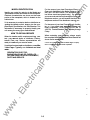
INCORRECT SERVICE OR REPLACEMENT OF PARTS CAN RESULT IN
DEATH, SEVERE PERSONAL INJURY, AND/OR EQUIPMENT DAMAGE.
SERVICE PERSONNEL MUST BE QUALIFIED TO PERFORM ELECTRICAL
AND/OR MECHANICAL SERVICE.
.
.
.c
om
Safety Precautions
If the cabinet must be opened for any reason:
ua
ls
1. Move the operation selector switch on the gen
erator set or Stop/ Auto/Handcrank switch on
the automatic transfer switch (whichever ap
plies) to Stop.
2. Disconnect the starting batteries of the gen
erator set (remove the ground [-] lead first).
tM
an
3. Remove AC power to the automatic transfer
switch. If the instructions require otherwise,
use extreme caution due to the danger of
shock hazard.
Place rubber insulative mats on dry wood platforms
over metal or concrete floors when working on any
electrical equipment. Do not wear damp clothing
(particularly wet shoes) or allow �kin su �aces to be
damp when handling any electncal equtpment.
Jewelry is a good conductor of electricity and
should be removed when working on the electrical
equipment.
Do not work on this equipment when mentally or
physically fatigued, or after consuming alcohol or
any drug that makes the operation of equipment
unsafe.
ww
w
.E
lec
tri
ca
lP
ar
This manual includes the following symbols to indi
cate potentially dangerous conditions. Read the
manual carefully and know when these conditions
exist. Then take the necessary steps to protect per
sonnel and the equipment.
t!1•M�®3;1 This symbol warns of Immediate
hazards that will resultIn severe persona/Injury
or death.
IAWARNINGI This symbol refers to a hazard or
unsafe practice that can result In severe per
sona/Injury or death.
[AcAUTION I This symbol refers to a hazard or
unsafe practice that can resultIn personal In
jury or product or property damage.
High voltage in OT transfer switch component� pre
sents serious shock hazards that can result rn se
vere personal injury or death. Read and follow
these suggestions.
Keep the transfer switch cabinet closed and locked.
Make sure only authorized personnel have the
cabinet and operational keys.
Due to the serious shock hazard from high voltages
within the cabinet, all service and adjustments to
the transfer switch must be performed only by an
electrician or authorized service representative.
OT3-UG-3
ii
.c
om
1. Introduction
OPERATOR'S MANUAL
NORMAL
ua
ls
This operator's manual provides information nec
essary for operation of an OT Ill transfer switch.
TRANSFER SWITCH APPLICATION
1
I
I
I
I
I
I
ar
lP
AUTOMATIC TRANSFER SWITCHES
ca
Automatic transfer switches, capable of automatic
operation without operator involvement, perform
the following basic functions:
1.
w
.E
lec
tri
Sense the interruption of the Normal power
source.
2. Send a start signal to the generator set (Emer
gency power source).
3. Transfer the load to the Emergency power
source.
4. Sense the return of the Normal power source.
5. Retransfer the load to the Normal power
source.
6. Send a stop signal to the generator set.
ww
LOAD
L_
tM
The load is connected to the common of the trans
fer switch (Figure 1-1). Under normal conditions,
the load is supplied with power from the Normal
source (as illustrated). If the Normal power source
is interrupted, the load is transferred to the Emer
gency power source. When Normal power returns,
the load is retransferred to the Normal power
source. The transfer and retransfer of the load are
the two most basic functions of a transfer switch.
I
I
an
Transfer switches are an essential part of a build
ing's standby or emergency power system. The
Normal power source, commonly the utility line, is
backed up by an Emergency power source, often
an electric generating set. A transfer switch sup
plies the electrical load with power from one of
these two power sources.
.----1
I
I
1-1
l
EMERGENCY
SC1101
FIGURE 1-1. LOAD TRANSFER SWITCH
(TYPICAL FUNCTION)
.c
om
MODEL IDENTIFICATION
For the name of your local Cummins®/Onan® or
Onan-only distributor in the United States or Can
ada, call 1-800-888-0NAN. (This automated serv
ice utilizes touch-tone phones only.) By entering
your area code and the first three digits of your local
telephone number, you will receive the name and
telephone number of the distributor nearest you.
Identify your model by referring to the Model and
Specification number as shown on the nameplate.
Electrical characteristics are shown on the lower
portion of the nameplate, which is located on the
cabinet door.
If it is necessary to contact a dealer or distributor re
garding the transfer switch, always give the com
plete Model, Specification, and Serial number. This
information is necessary to properly identify your
unit among the many types manufactured.
ua
ls
For the name of your local Cummins-only distribu
tor, or if you need more assistance, please call
Onan Corporation, 1-612-574-5000, 7:30 AM to
4:00 PM, Central Standard Time, Monday through
Friday.
HOW TO OBTAIN SERVICE
When contacting your distributor, always supply
the complete Model Number and Serial Number as
shown on the nameplate.
an
When the transfer switch requires servicing, con
tact your nearest dealer or distributor. Factory
trained Parts and Service representatives are
ready to handle all your service needs.
Cummins is a registered traclemal1< of Cummins Engine Company.
Onan is a registered trademal1< of Onan Corporation.
tM
If unable to locate a dealer or distributor, consult the
Yellow Pages. Typically, our distributors are listed
under:
ww
w
.E
lec
tri
ca
lP
ar
GENERATORS-ELECTRIC,
ENGINES-GASOLINE OR DIESEL, OR
RECREATIONAL VEHICLE5-EQUIPMENT,
PARTS AND SERVICE.
1 -2
Automatic transfer switches control transfer of the
load to the Normal power source or to the Emer
gency power source {generator set) without opera
tor involvement. Throughout this manual, frequent
references are made to two-wire and three-wire
start-stop functions of generator sets. Water
cooled generator sets have two-wire start controls
and the air-cooled sets have three-wire start con
trols.
ua
ls
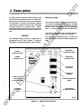
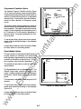
The Normal Connected lamp is lit when the auto
matic transfer switch is in the normal position.
The Emergency Connected lamp is lit when the
automatic transfer switch is in the emergency posi
tion.
ar
tM
The standard cabinet {Figure 2-1) meets the re
quirements for a UL Type 1 cabinet. This type is
designated as a general-purpose, indoor cabinet.
There are four indicator lamps on the cabinet door.
The Normal Available and Emergency Available
lamps are lit whenever their corresponding power
sources (utility or generator set) are producing
power. These two lamps can be lit simultaneously.
an
CABINET
Indicator Lamps
.c
om
2. Description
lP
NORMAL
CONNECTED LAMP
EMERGENCY
AVAILABLE LAMP
ca
NORMAL
AVAILABLE LAMP
EMERGENCY
CONNECTED LAMP
tri
OPTIONAL AC
VOLTMETER
lec
OPTIONAL AC
AMMETER
PHASE SELECTOR
SWITCH (FOR
OPTIONAL METERS)
.E
OPTIONAL FREQUENCY
METER
TEST/NORMALJ
RETRANSFER SWITCH
ww
w
OPTIONAL
AUTO/MANUAL
SWITCH
M1694-48
FIGURE 2-1. CABINET WITH OPTIONS
2-1
.c
om
TRANSFER SWITCH
Test/Normai/Retransfer Switch
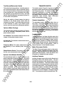
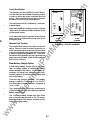
The transfer switch (Figure 2-2) opens and closes
the contacts that transfer the load between Normal
and Emergency power. The transfer switch is me
chanically interlocked to prevent simultaneous
closing to both power sources. The main parts of
the transfer switch discussed here are the contact
assemblies, linear actuator, Motor Disconnect
switch, and auxiliary contacts.
ua
ls
This switch has three positions. In the Normal posi
tion, the transfer switch is set for automatic opera
tion. Moving the switch to Test sends a start signal
to the generator set. After the transfer time delay,
the generator set will assume the load-provided
that the Test With/Without Load switch (Figure 2-2)
is in the With Load position.
Moving the switch to Normal causes the load to
retransfer to the Normal power source after the
retransfer time delay. To avoid the delay and cause
a fast retransfer of load to the Normal power
source, move the switch to the Retransfer position.
Contact Assemblies
The automatic transfer switch has either three or
four poles. Three pole transfer switches are pro
vided with a neutral bar. The contact assemblies
make and break the current flow. When closed to
either the Normal or the Emergency power source,
the contacts are mechanically held. A mechanical
interlock prevents them from closing to both power
sources at the same time.
an
Optional Meter Package
tM
The optional meter package includes an AC amme
ter, an AC voltmeter, a frequency meter, and a
phase selector switch.
Linear Actuator
AC Voltmeter: The voltmeter measures line-to-line
voltage of the selected power source.
ar
The linear actuator is a linear induction motor that
moves the contact assemblies between the Normal
power source and the Emergency power source.
Linear actuator operation is initiated automatically
with automatic transfer switches. Manual operation
of the transfer switch is also possible. Refer to
Manual Operation in the Operation section.
lP
AC Ammeter:The ammeter measures the line cur
rents of the load.
Frequency Meter: This meter measures the out
put frequency of the selected power source in
hertz.
ca
Motor Disconnect Switch
tri
Phase Selector Switch: This switch is used to se
lect the source and phase to be measured.
Optional Auto/Manual Switch
Auxiliary Contacts
lec
The Auto/Manual switch is used to enable or dis
able the automatic retransfer function. This switch
has two positions. In the Auto position, normal auto
matic retransfer is enabled. In the Manual position,
automatic retransfer (from a functioning generator
set back to utility power) is disabled; only manual
retransfer (using the Test/NormaVRetransfer
switch) is possible. In the event of generator set
failure, however, the Power Sentry control logic will
ignore the Auto/Manual switch and initiate retrans
fer to utility power.
.E
Auxiliary contacts are provided on the Normal and
Emergency sides of the transfer switch. They are
actuated by operation of the transfer switch during
transfer and retransfer. The Normal side auxiliary
contact switch is actuated when the transfer switch
is in the Normal position. The Emergency side aux
iliary contact switch is actuated when the transfer
switch is in the Emergency position. The auxiliary
contacts have current ratings of 10 amperes at 250
VAG. The contacts are wired to terminal block TB1.
w
ww
The Motor Disconnect toggle switch, on the acces
sory control panel, enables and disables the linear
actuator. Place the switch in the Auto position to
enable the linear actuator. Place the switch in the
Ott position to disable the linear actuator.
2-2
.c
om
TEST & EXERCISE
WITH/WITHOUT
LOAD SWITCHES
OPTIONAL
PROGRAMMED
TRANSITION
POWER
SENTRY
CONTROL
ua
ls
OPTIONAL
SIGNAL
MODULE
INDICATOR
LAMPS
0
C!l
i
i
an
OPTIONAL
METERS
0
0
0
0
lP
ar
tM
OPTIONAL
3-WIRE
START
ACCESSORY
CONTROL
PANEL
AUTOMATIC
TRANSFER
SWITCH
ca
MOTOR
DISCONNECT
SWITCH
tri
SC1581
FIGURE 2-2. INTERIOR/COMPONENTS
The most important component of the electronic
control system is the Power Sentry control (Figure
2-2). The Power Sentry includes voltage sensing
circuits, time delay circuits and control relays.
There are also several adjustment potentiometers
and indicator lamps on the Power Sentry. The ad
justments must be performed only by qualified
service personnel.
lec
ELECTRONIC CONTROL SYSTEM
This section describes the standard and optional
components of the electronic control system.
.E
I AWARNINGI Improper calibration or adjustment
of electronic control modules can cause death,
severe persona/Injury, and equipment or prop
erty damage. Calibration and adjustment of
these components must be performed by tech
nically qualified personnel only.
w
IAWARNINGI Accidental actuation of the linear
motor could cause severe personal Injury. Dis
able the motor, as described below, before
making any adjustments.
ww
All calibration and adjustment procedures are de
scribed in the Installation manual (which was
shipped with the transfer switch) and in the Service
manual {which is available through your distribu
tor).
Place the Motor Disconnect Switch (Figure 2-2)
In the Off position when making adjustments.
Return the switch to the Auto position after ad
justments are completed.
2-3
.c
om
IAwARNING I AC power within the cabinet and the
rear side of the cabinet door presents a shock
hazard that can cause severe persona/Injury or
death. Use extreme caution to avoid touching
electrical contacts when the cabinet door Is
open.
ages for an undervoltage condition and generate
signals, which are sent to the time delay module. If,
for example, an under- voltage condition is sensed
on the Normal source, the voltage sensor module
sends a signal to the time delay module that initi
ates and controls the timing for generator set start
and the transfer of load.
Power Sentry Time Delays
The standard transfer switch has undervoltage
sensing for all phases of the Normal and Emer
gency power sources.
Overvoltage and Frequency Sensing
Option
Overvoltage and frequency sensing are available
as a single option.
an
Overvoltage Sensing: With optional overvoltage
sensing, the Normal and Emergency sources are
monitored for an overvoltage condition.
tM
As with the standard undervoltage sensing, the
voltage sensors signal the time delay module,
which controls the transfer or retransfer sequence.
An adjustable time delay (0 to 120 seconds) over
rides momentary overshoots in voltage.
ar
To set this time delay, align the slot on the potenti
ometer with the desired marking on the Power Sen
try cover.
Stop Time Delay: This delay is adjustable from 0 to
10 minutes. It begins timing when the load is
retransferred to the Normal power source. At the
end of the delay, the stop signal is sent to the gen
erator set. This time delay allows the generator set
to cool down at no load before stopping.
To set this time delay, align the slot on the potenti
ometer with the desired marking on the Power Sen
try cover.
Transfer Time Delay: This delay begins when
generator voltage and frequency reach the settings
of the control. After the delay, the transfer switch
transfers the load to the Emergency power source.
This brief time delay allows the generator set to sta
bilize before the load is applied. It has an adjust
able range of 0 to 120 seconds.
To set this time delay, align the slot on the potenti
ometer with the desired marking on the Power Sen
try cover.
ua
ls
Start Time Delay: This delay is adjustable from 0 to
15 or (optionally) from 0 to 90 seconds. This brief
time delay prevents generator set starting during
power interruptions of short duration. Timing starts
the moment of Normal (utility) power interruption. If
the duration of interruption exceeds the delay time,
the control system signals the generator set to
start.
tri
ca
lP
To set this time delay, align the slot on the potenti
ometer with the desired marking on the Power Sen
try cover.
As with the standard undervoltage sensing, the fre
quency sensors signal the time delay module,
which controls the transfer or retransfer sequence.
lec
An adjustable time delay (0 to 15 seconds) allows
the control to ignore momentary dips or rises in fre
quency.
Retransfer Time Delay: This delay begins the mo
ment Normal line voltage and frequency return. Af
ter the delay, the transfer switch can retransfer the
load to the Normal source. The delay allows the
Normal source to stabilize before retransfer. It has
an adjustable range of 0 to 30 minutes.
.E
To set this time delay, align the slot on the potenti
ometer with the desired marking on the Power Sen
try cover.
Two-Wire Starting
The starting circuit is a basic supervisory function of
the electronic control. Water-cooled generator sets
use a two-wire start control.
w
To set this time delay, align the slot on the potenti
ometer with the desired marking on the Power Sen
try cover.
Although the logic is more involved, the two-wire
starting circuit can be thought of as a single pole,
single throw switch. A closed switch signals the
generator set to start. An open switch signals the
electric generator set to stop.
Undervoltage Sensing
ww
Frequency Sensing: With optional frequency
sensing, the Normal and Emergency sources are
monitored for variations in frequency. The sensors
determine whether the source is within an adjust
able bandwidth.
Two voltage sensors, one for the Normal side and
one for the Emergency side, monitor source volt2-4
®
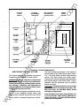
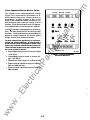
The optional three-wire starting control (available
on 40- to 125-ampere switches only) enables the
transfer switch to start and stop a three-wire start
generator set. Three-wire starting logic is similar to
a single-pole, double-throw switch. A common is
closed to one side to send a start signal, and to the
opposite side to send a stop signal. In addition to
start and stop functions, the control has an over
crank relay, a preheat relay, two Timing lamps, a
Lockout Lamp, a Reset Switch, and a Auto/Stop/
Handcrank Switch (Figure 2-3). The 3-Wire Start
module may be equipped with a preheat timer On
Off switch.
@
Stop
(Saconda)
ua
ls
®
�
1
©
�
an
Ovarcrank
Reaat
>
0
Daley
(Seconda)
e
#
0
eo
�
e
#
0
Lockout
120
e
®
SC1573-2a
tM
AGURE 2-3. 3-WIRE START MODULE
ar
lP
ca
tri
The Auto/Handcrank/Stop switch has three posi
tions that function as follows:
.E
lec
Allows the generator set to start and
assume the load if a power outage oc
curs. This Is the normal operating
position.
Shuts down the generator set and
prevents it from starting. Use this
position when servicing the gen
erator set.
w
011l=lan
�
c
=
To set the timers, align the slots on the potentiome
ters with the desired markings on the faceplate
(Figure 2-3).
ww
0.
*
Timing
Timing
If used, the preheat timer delays the start signal (0
to 60 seconds) while a preheat output is energized.
The Preheat Timing lamp is on during this delay.
Handcrank:
•
J11
®
3 Wire Start
CD
.r::.
CD Delay
..
A set of overcrank alarm contacts are also pro
vided. The contacts can be used to energize an ex
ternal overcrank alarm.
Stop:
Handcrank
10
Overcrank occurs when the generator set does not
start within the adjustable time limit (0 to 120 sec
onds). In order to protect the starter motor, over
crank relay contacts open the starting circuit and
light the Lockout lamp. After a starting problem is
corrected, pressing the Overcrank Reset switch re
sets the circuit. Refer to the Operation Section.
Auto:
Auto
.c
om
Three-Wire Starting Option
Prevents the automatic transfer
switch from starting the generator set,
but allows starting and stopping at the
set. Use this position for generator
set maintenance.
Connections for the optional 3-Wire Start module
are made at TB3.
2-5
®
.c
om
Programmed Transition Option
®
Timing
��:lDelaayy �Delay
The optional Program Transition module (Figure
2-4) is used to introduce a pause during transition.
Programmed transition allows the transfer switch to
assume a mid-transition position for an adjustable
interval of time. In this position, the load is not con
nected to either (Normal or Emergency) power
source.
0
L..=..
®
8
(Second a)
J30
1
ua
ls
�
This feature allows residual voltage from inductive
loads to decay to an acceptable level before trans
fer is completed. The length of time that the transfer
switch is in the midposition can be adjusted from 0
to 7.5 seconds or 0 to 60 seconds, depending on
the timer option. The proper adjustment is a func
tion of the load.
80
Program
Transition
®
SC1583
an
FIGURE 2-4. PROGRAM TRANSITION MODULE
tM
To set the time delay, align the slot on the potenti
ometer with the desired marking on the faceplate
(Figure 2-4).
ar
If a time delay is desired, make sure that the Delay/
No Delay switch is in the Delay position.
Signal Module Option
ca
lP
The main function of the optional Signal Module is
to delay transfer (or retransfer) for a preset time
while operating a signal contact to give warning that
a transfer (or retransfer) is about to occur. This op
tion is typically used in elevator applications.
No
�Delay
Delay
®
.......,:::-
Signal Module
®
16
tri
This module also provides four other sets of form C
signal contacts.
The Signal Module has one adjustable timer. The
Elevator Signal delay controls the timing of two
events. It delays transfer/retransfer and energizes
the Elevator Transfer Signal relay during the delay
period.
J21
a)
lec
1.§
Ch
1-!::::
This time delay is adjustable over a range of 0 to 50
seconds.
.E
®
0
a;
�
w
Delay
(Seconds)
•
�
0
50
®
SC1584
To set the time delay, align the slot on the potenti
ometer with the desired marking on the faceplate
(Figure 2-5).
FIGURE 2-5. SIGNAL MODULE
w
If a time delay is desired, make sure that the Delay/
No Delay switch is in the Delay position.
ww
1
Timing
2-6
J
The optional Load Shed function is used to discon
nect the load from an available Emergency source
in order to reduce the power consumed from that
source. When the load shed function is initiated,
the switch is moved to the neutral position.
0
0
MTJER't()UINJER
J
1Z/MIIOlT
...
@
The load shed function is initiated by a customer
supplied signal.
... .....
ua
ls
'''""
\IOlTACJE
-
'il'
When load shedding is in effect, a return of Normal
utility power will cause immediate retransfer to the
Normal power source.
r;;-
[:
..
...
.
'--
0
If the load shed signal is removed before Normal
power returns, the switch will transfer back to the
Emergency side.
ES1612
0
an
2-AMP
CHARGER
Remote Test Transfer
0
SC1613
10-AMP
CHARGER
FIGURE 2-6. BATTERY CHARGER
Float Battery Charger Option
lP
ar
tM
The transfer switch may be wired with a remote test
switch. Closure of a set of contacts across the re
mote test transfer inputs causes the transfer switch
to sense a (simulated ) utility power failure and send
a start/run signal to the generator set. The load is
transferred to the generator set when generator set
power becomes available. (Refer to the Installation
and Service manuals. )
tri
ca
A float-charge battery charger (Figure 2-6) regu
lates its charge voltage to continuously charge
without damage to the battery. As the battery ap
proaches full charge, the charging current auto
matically tapers to zero amperes or to steady-state
load on the battery.
lec
There are two chargers available. One battery
charger is rated for 10 amperes at 12 or 24 VDC.
The other battery charger is rated for 2 amperes at
12 or 24 V DC.
.E
The 2-ampere battery charger has an ammeter to
indicate charging current and a fuse to protect the
battery charger circuit.
w
The 10-ampere battery charger has three fuses
(two on the AC input and one on the DC output),
three fault display LEOs, and an ammeter for indi
cation of charging current.
ww
.c
om
Load Shed Option
2-7
.c
om
On the 1 0-ampere charger, three sets of (form C)
alarm contacts (corresponding to the three fault
LEOs) are also available. Using an optional alarm
contact harness, these contacts can be wired by
the installer to activate other audible or visual
alarms.
Alar• Module
ua
ls
Under normal operating conditions, the Low Bat
and AC Fail relays are energized and the High Bat
relay is de-energized. In response to a Low Bat or
AC Fail condition, the appropriate normally ener
gized relay (Low Bat or AC Fail) drops out. In re
sponse to a High Bat condition, the normally de-en
ergized High Bat relay is energized.
0
0
Het-n
Stlenoeol
an
Auxiliary Relay Option
0
Optional auxiliary relays provide contacts tor ener
gizing external alarms, remote indicators, and con
trol equipment such as louver motors and water
pumps.
tM
FIGURE 2-7. ALARM MODULE
Alarm Module Option
ar
The optional alarm module (Figure 2-7) provides an
audible indication that the transfer switch has trans
ferred to the emergency power source.
lP
A push button on the alarm module provides a
means to silence the horn.
tri
ca
The Alarm lamp indicates that the transfer switch is
in the Emergency Connected position. If the horn is
silenced, the Horn Silenced lamp will also light.
Both lamps will stay lit until the transfer switch
moves from the Emergency Connected position to
the disconnected (neutral) or Normal Connected
position.
0
lec
Exerciser Clock Option
The exerciser clock initiates generator set start/run
cycles at programmable intervals and for program
mable durations. It is a 7-day, 24-hour clock that
can store and execute up to ten start/stop programs
(exercise cycles).
}---1�0
.E
Oflf)
o: a a
1
J---t-- cm:> •
Programming the exerciser clock requires setting
the time of day and entering the exercise start and
stop times.
ww
w
Refer to the circled numbers in Figure 2-8 when
reading the following instructions.
FIGURE 2-8. EXERCISER CLOCK
2-8
.c
om
To set the time of day:
5. To enter the complete start/stop program,
press the Pr button (8). If all program require
ments have been satisfied, the display returns
to the time of day. lf the program requirements
are not met, the display of the section that
needs correction flashes on and off.
1. If you are performing installation and setup,
press the R button (9) with the tip of a ball point
pen to reset all memory. Do not press the R
button if you are only changing the time of day.
2. Press the clock button (1).
To enter more programs, repeat the two 5-step pro
cedures. A maximum of ten programs can be en
tered. (The same ten programs can be repeated
each day.)
ua
ls
3. Press the h button (3) to set the hour of the day.
The clock uses 24-hour (military) time.
4. Press them button (4} to set the minutes of the
hour.
The word "Full" appears in the display when the
memory is full.
5. Press the 1-7 button (5) to advance the indica
tor bar over the desired day number. (Use the
1 to represent Sunday.)
If the 1/0 button (2) is pressed and no program is to
be entered, press the Ch button (6) and then the Pr
button (8) to get out of the program mode.
an
6. Press the Pr button (8) to enter the time.
To set the exercise start time:
To check the programs:
1. Slide the output selector switch (16) to the cen
ter position. The output selector switch has
three positions. The Off position overrides the
program and causes an exercise stop. The I
position overrides the program and causes an
exercise start. The center position selects pro
gram control.
tM
1. Press the Ch button (6). An "I" (12} and an "0"
(15) are displayed.
ar
2. Press the Ch button (6) again. The start and
stop information for the first program is dis
played.
lP
2. Press the 1/0 button (2). An "I" (12) appears in
the upper display window. The "I" is a symbol
for start time.
3. Press the h button (3) to set the start hour.
ca
4. Press the m button (4) to set the start minute.
4. Press the Pr button (8) to return to the time-of
day display.
5. Press the 1-7 button (5) to advance the indica
tor bar (13) from 1 to 7 and back to 1. For each
day to be selected for exercise, press the Q
button (7) when the indicator is over the de
sired day number. (1 represents Sunday.)
tri
To change (edit) a program:
1. Press the Ch button (6} until the program you
want to change appears in the display window.
To set the exercise stop time:
lec
2. Press the 1/0 button (2) to select start or stop
time.
1. Press the 1/0 button (2). An "0" (15) appears in
the lower left display window. The "0" is a sym
bol for stop time.
3. Press the h (3), m (4), or 1-7 (5) and Q (7) but
tons to change the hour, minute, or day.
2. Press the h button (3) to set the stop hour.
.E
4. Press the Pr button (8) to enter the edited pro
gram and return to the time-of-day display.
3. Press the m button (4) to set the stop minute.
4. Press the 1-7 button (5) to advance the indica
tor bar (14) from 1 to 7 and back to 1. For each
start time (selected in step 5 above), there
must be a corresponding stop time. A program
can start on day 2, pass through midnight, and
stop on day 3 (for example); but there must be
a stop time for every start time. Press the Q
button (7} when the indicator is under the de
sired day number.
To erase (clear) a program:
1. Press the Ch button (6} until the program to be
erased is displayed.
w
ww
3. Continued pressing of the Ch button (6)
causes the display to sequence through all of
the programs in memory. lf ten programs have
been entered, the word "Full" appears after the
tenth program display.
2. Press the C button (10) with a ball point pen to
clear the program.
3. Press the Pr button (8) to return to the time-of
day display.
2-9
.c
om
Phase Sequence/Balance Monitor Option
•
6
aoo
tM
�
ME
I.NIM.NCE
TOTB2, 7 & 8
10
1140
�
I
10
�
307-2801c
ar
FIGURE 2·9. PHASE SEQUENCE
BALANCE MONITOR
.E
lec
w
ww
-
an
I
tri
•
e
CMill
WILTME
0. ··�-- '0.••
lP
•
e
r=lua.
4
ca
•
e
�
-Hum
The relay dropout delay applies only to over/under
voHage and voltage unbalance. In the event that a
phase reversal or loss of one phase Is sensed, relay
dropout occurs within 100 milliseconds (maximum).
There Is NO relay dropout delay when a phase rever
sal or loss of phase Is sensed.
Overvoltage dropout occurs at normal voltage
+ 10% (±2<>/o).
Undervoltage dropout occurs at normal volt
age -10% (±2%).
Dropout time delay range is 2 to 20 seconds.
Percent voltage unbalance range is 2 to 6% on
240- and 480-volt units.
Percent voltage unbalance range is 2 to 8% on
380-volt units.
C Phase
ua
ls
e
m-..
Five LEOs indicate normal operation or fault condi
tions. The Relay Energized LED is lit during normal
operation. Three potentiometers permit setting the
percent of voltage unbalance, the normal system
voltage, a.nd the relay dropout time delay.
•
B Phase
A Phase
The optional phase sequence/balance monitor
(Figure 2-9) is connected to-and senses-A, B,
and C phases of utility power. If there is an over- or
undervoltage, a phase reversal, a loss of one
phase, or an unbalanced voltage condition; a nor
mally energized relay drops out, closing a set of
contacts. When these contacts close, the genera
tor set start/transfer of load sequence is initiated.
2-10
.c
om
3. Operation
AUTOMATIC OPERATION
3.
Place control switches in the positions given below.
Transfer - from the Normal to the Emer
gency power source:
A. Pull the upper manual operator handle
down.
B. Push the lower manual operator handle
down.
ua
ls
Test/Normai/Retransfer switch:
•
Normal position.
Motor Disconnect switch:
•
Auto position.
Retransfer- from the Emergency to the Nor
mal power source:
Operation selector switch (engine control):
•
Remote position. (Two-wire start for water
cooled generator sets only. )
an
C. . Pull the lower manual operator handle up.
D. Push the upper manual operator handle
up.
4. Before moving the Motor Disconnect switch
back to the Auto position, remember the trans
fer switch will transfer load to the active power
source. ( If both power sources are available, it
will transfer the load to the Normal source. )
Stop/Auto/Handcrank switch:
•
Auto position. (Three-wire start for air-cooled
generator sets only. )
tM
The generator set must also be set for automatic
operation.
IAWARNINGI Automatic transfer switch op
eration results In rapid movement of the
manual operator handles and presents a
hazard of severe personal injury. Keep
hands clear of handles when switching
back to automatic operation.
ar
MANUAL OPERATION
lP
The transfer switch has operator handles for manu
ally transferring the load. Use the following proce
dure:
5. Move the Motor Disconnect switch to the Auto
position.
6. Close the cabinet door.
If possible, remove all AC power to the transfer
switch before manually operating the switch. If
It Is necessary to perform manual operation
with AC power connected, follow the "Safety
Related Worlc Practices .. listedIn NFPA 70E.
Run the generator for at least 30 minutes once
each week with at least 50 percent load (if possi
ble). If you do not have an optional exerciser, use
the Test/NormaVRetransfer switch, as described
below, to test the generator set each week.
1 Open the cabinet door of the automatic trans
fer switch.
The optional exerciser has preselected exercise
periods and exercises the generator set automati
cally with or without load, depending on the position
of the Exercise With/Without Load switch. If the
Normal power source has an interruption while the
generator set is exercising without load, the auto
matic transfer switch will transfer the load to the
generator set.
ca
IAwARNINGI ACpower within the cablnet and the
rear side of the cabinet door presents a shock
hazard that can cause severe personal injury or
death. Use extreme caution to avoid touching
electrical contacts whenever the cabinet door
is open.
.
lec
tri
GENERATOR SET EXERCISE
ww
w
.E
2. Move the Motor Disconnect switch to the Off
position.
3-1
.c
om
The Test With/Without Load selector switch
must be In the With Load p osition In order to
test with load.
GENERATOR SET START TEST
IA WARNING I AC power within the cabinet and the
rear side of the cabinet door presents a shock
hazard that can cause severe persona/Injury or
death. Use extreme caution to avoid touching
electrical contacts whenever the cabinet door
Is open.
2. Close the cabinet door.
IAwARNINGI AC power within the cabinet
and the rear side of the cabinet door pre
sents a shock hazard that can cause severe
persona/Injury or death. Close the cabinet
door.
ua
ls
1. Place the Test With/Without Load selector .
switch, on the Power Sentry control, in the
Without Load position.
3. Move the Test/Normai/Retransfer switch to
Test. The generator set should start and as
sume the load after the transfer time delay.
The Test With/Without Load selector switch
must be In the Without Load position.
2. Close the cabinet door.
4. At the end of the test period, move the Test/
NormaVRetransfer switch to the Normal posi
·
tion if you want to retransfer load back to the
Normal power source after the retransfer time
delay. To bypass the retransfer time delay and
cause immediate load retransfer, move the
Test/NormaVRetransfer switch to Retransfer
and release (the switch will return to Normal).
The generator will stop after the stop time de
lay.
14WABNtNGJ
tM
an
AC power within the cabinet
and the rear side of the cabinet door pre
sents a shock hazard that can cause severe
persona/Injury or death. Close the cabinet
door.
3. Move the Test/NormaVRetransfer switch to
Test. The generator set should start and run.
ar
4. At the end of the test period, move the Test/
Normai/Retransfer switch to the Normal posi
tion. The generator will stop.
ca
lP
5. In anticipation of scheduled or automatic gen
erator set exercise, check that the With/With
out Load selector switches are in the desired
positions. Refer to Generator Set Exercise.
5. In anticipation of scheduled or automatic gen
erator set exercise, check that the With/With
out Load selector switches are in the desired
positions. Refer to Generator Set Exercise.
6. Close and lock the cabinet door.
6. Close and lock the cabinet door.
tri
WITH-LOAD STANDBY SYSTEM TEST
IAWARNINGI AC power within the cabinet and the
rear side of the cabinet door presents a shock
hazard that can cause severe persona/Injury or
death. Use extreme caution to avoid touching
electrical contacts whenever the cabinet door
is open.
lec
An overcrank condition exists when the generator
set fails to start within the overcrank time limit.
When this condition occurs, the Lockout lamp on
the 3-Wire Start module will light. To reset the auto
matic starting circuit:
1. Correct the engine starting problem.
Place the Test With/Without Load selector
switch, on the Power Sentry control, in the With
Load position.
2. Push the Overcrank Reset button inward and
release to reset the overcrank relay.
ww
w
.E
1.
OVERCRANK RESET
(3-Wire Start Only)
3-2
.c
om
PREVENTIVE MAINTENANCE
Performing the yearly preventive maintenance procedures in Table 3-1 will result in operational reliability of
the transfer switch.
The following procedures must only be performed by technically qualified personnel, following the proce
dures provided in the Service manual (962-0512). If repair or replacement of components is necessary,
call your dealer or distributor.
ua
ls
IAWARNINGI ACpower within the cabinet and the rear side of the cabinet door presents a shock hazard
that can cause severe personal injury or death. In addition, incorrect installation, service, or parts
replacement can result in severe personal injury, death, and/or equipment damage. Therefore, all cor
rective service procedures must only be performed by technically qualified personnel, following the
procedures provided in the Service manual (962-0512).
an
IAWARNINGI The transfer switch presents a shock hazard that can cause severe persona/Injury or
death unless all ACpowerIs removed. Be sure to move the generator set operation selector switch to
Stop, disconnect AC line power, disconnect the battery charger from Its AC power source, and dis
connect the starting battery (negative [-] lead first) before servicing.
IAWARNING!Ign/t/on of explosive battery gases can cause severe personal injury. Do not smoke or
cause any spark, arc, or flame while servicing batteries.
TABLE 3-1. ANNUAL PREVENTIVE MAINTENANCE
tM
1. DISCONNECT ALL SOURCES OF AC POWER:
ar
Disconnect both AC power sources from the transfer switch before continuing. Turn the generator
set operation selector switch to Stop. (The selector switch is located on the generator set control
panel.) If there Is an external battery charger, disconnect it from Its AC power source. Then
disconnect the set starting battery (negative [-] lead first).
2. CLEAN
lP
a. Thoroughly dust and vacuum all controls, meters, switching mechanism components, interior
buswork, and connecting lugs.
b. Close the cabinet door and wash exterior surfaces with a damp sponge (mild detergent and
water). Do not allow water to enter the cabinet, especially at meters, lamps, and switches.
ca
3. INSPECT
lec
tri
a. Check buswork and supporting hardware for carbon tracking, cracks, corrosion, or any other
types of deterioration. If replacement is necessary, call your dealer or distributor.
b. Check stationary and movable contacts. If contact replacement is necessary, the procedures
are described in section 4 of the Service manual (962-0512).
c. Check system hardware for loose connections. Tighten as indicated in step 4.
d. Check all control wiring and power cables (especially wiring between or near hinged door) for
signs of wear or deterioration.
e. Check all control wiring and power cables for loose connections. lighten as indicated in step 4.
f. Check the cabinet interior for loose hardware. Tighten as indicated in step 4.
.E
4. PERFORM ROUTINE MAINTENANCE
a. Tighten buswork, control wiring, power cables, and system hardware, as necessary. Hardware
torque values are given in section 4 of the Service manual (962-0512). Retorque all cable lug
connections. Lug torque requirements are listed in section 1 of the Service manual.
b. Service or replace the batteries.
ww
w
5. CONNECT AC POWER AND CHECK OPERATION
a. Connect the set starting battery (negative [-] lead last). Connect the normal AC power source,
enable the backup power source. If applicable, connect power to the battery charger.
b. Verify proper operation of the battery charger.
c. Test system operation as described in this section. Close and lock the cabinet door.
3-3
w
ww
.E
tri
lec
an
tM
ar
lP
ca
ua
ls
.c
om
.c
om
4. Troubleshooting
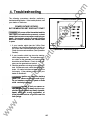
The following procedures describe preliminary
troubleshooting checks. If the trouble persists, call
your dealer or distributor.
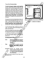
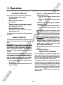
"1" INDICATES EXERCISE PERIOD
[�,L.·•Jiij
ua
ls
0
POWER OUTAGE OCCURS,
BUT GENERATOR SET DOES NOT START
1
1
IAWARNINGI ACpower within the cabinet and the
rear side of the cabinet door presents a shock
hazard that can cause severe personal injury or
death. Use extreme caution to avoid touching
electrical contacts whenever the cabinet door
is open.
n nn
Ll ·U Ll
·
_
2 3 4 5 II 7
-
0
Off(!}
n-nn
U·UU
v
"
liiii)
"'
liiiiii)
1-7
iiii)
c..
iiii)
a
Iii)
Pr
�
J
CJID 1
an
/
C.R.
SUDE
SWITCH
tM
1. If your transfer switch has the 3-Wire Start
module, the Auto/Stop/Handcrank switch on
the 3-Wire Start module should be set to Auto.
Check for overcrank condition. (See Operation
Section).
FIGURE 4-1. EXERCISER CLOCK
lP
ar
2. If your transfer switch has two-wire starting,
check the generator set. The operation selec
tor switch on the generator set control panel
should be set at Remote. Check for fault indi
cators on the generator set control.
tri
ca
3. Start the generator set using its start-stop con
trols. If it does not crank, check the starting bat
teries. If it cranks but does not start, check the
fuel supply. If the problem persists, call your
dealer or distributor.
lec
IAWARNINGI Ignition of explosive battery
gases can cause severe personal Injury.
Do not smoke or cause any spark or flame
while servicing batteries.
w
.E
IAWARNINGI Ignition of fuel can cause se
vere persona/Injury or death by fire or ex
plosion. Do not permit any flame, cigarette,
spark, pilot light, arcing equipment, or
other possible source of Ignition near the
fuel system.
ww
/
4-1
0
SC1579
1.
(for air-cooled gen
erator sets): The Auto/Stop/Handcrank switch
on the 3-Wire Start module should be set at
Auto.
3. Check the exerciser to see if it is in an exercise
period. When the exerciser clock is in an exer
cise period, a "1" appears in the upper right
hand corner of the display window (Figure
4-1 ). You can view the display by looking
through the transparent clock cover. Check
that the red slide switch is in the center posi
tion.
4. Start the generator set using its start-stop con
trols. If it does not crank, check the starting
batteries. If it cranks but does not start, check
the fuel supply. If the problem persists, call
your dealer or distributor.
Two-wire starting only (for water-cooled gen
erator sets): The operation selector switch on
the generator set control panel should be set at
Remote.
T hree-wi re starting only
ua
ls
IAWARNINGI AC power within the cabinet
and the rear side of the cabinet door pre
sents a shock hazard that can cause severe
persona/Injury or death. Use extreme cau
tion to avoid touching electrical contacts
whenever the cabinet door is open.
(for air-cooled gen
erator sets): The Auto/Stop/Handcrank switch
on the 3-wire start module should be set at
Auto.
3. Check the Test/NormaVRetransfer switch to
make sure it is in the Normal position.
4. Check the exerciser clock to see if it is in an ex
ercise period. When the exerciser clock is in
an exercise period, a "1" appears in the upper
right-hand corner of the display window (Fig
ure 4-1). You can view the display by looking
through the transparent clock cover. Check
that the red slide switch is in the center posi
tion.
an
Three-wire starting only
tM
IAwARNINGI Ignition of explosive battery
gases can cause severe personal Injury.
Do not smoke or cause any spark or flame
while servicing batteries.
IAwARNINGI/gn/tlon of fuel can cause se
vere persona/Injury or death by fire or ex
plosion. Do not permit any flame, cigarette,
spark, pilot light, arcing equipment, or
other possible source of Ignition near the
fuel system.
lP
ar
2.
.c
om
2.
GENERATOR SET STARTS
DURING NORMAL POWER SERVICE
ca
If the exercise period occurs at an unexpected
time or for an excessive duration, refer to the ex
erciser clock programming procedure or call
your dealer or distributor.
tri
5. Momentary voltage dips might cause voltage
sensors to initiate generator set starting. If the
problem persists, call your dealer or distribu
tor.
1.
lec
GENERATOR SET DOES NOT EXERCISE
(IF EQUIPPED WITH EXERCISER)
1. Check the output voltage of the emergency
power source by observing the voltmeter on
the generator set or the optional voltmeter on
the automatic transfer switch.
2. Open the cabinet door and check to see if the
Motor Disconnect switch is in the Auto position.
IAWARNINGI AC power within the cabinet
and the rear side of the cabinet door pre
sents a shock hazard that can cause severe
persona/Injury or death. Use extreme cau
tion to avoid touching electrical contacts
whenever the cabinet door Is open.
Two-wire starting only (for water-cooled gen
.E
erator sets): The operation selector switch on
the generator set control panel should be set at
Remote.
IAwARNINGI AC power within the cabinet
and the rear side of the cabinet door pre
sents a shock hazard that can cause severe
persona/Injury or death. Use extreme cau
tion to avoid touching electrical contacts
whenever the cabinet door Is open.
3. Check the Source 2 Available lamp on the
Power Sentry.
4. Manually transfer the switch (see Operation).
Call your dealer or distributor.
w
ww
AFTER A POWER FAILURE,
G ENERATOR SET STARTS
BUT DOES NOT ASSUME LOAD
4-2
.c
om
AFTER POWER RETURNS,
TRANSFER SWITCH DOES NOT RETURN
TO NORMAL POSITION
GENERATOR SET CONTINUES TO RUN
AFTER RETRANSFER OF LOAD
TO NORMAL POWER
1. The retransfer time delay period may not have
expired. Check the Retransfer Timing lamp on
the Power Sentry.
The stop time delay function may not have expired.
Check the Stop Timing lamp on the Power Sentry.
Stop the generator set with its Start/Stop switch,
and call your dealer or distributor.
2. Open the cabinet door and check the Motor
Disconnect switch position. For automatic op
eration, it should in the Auto position.
ua
ls
BATIERY CHARGER FAILS TO CHARGE
{IF EQUIPPED)
Check the battery charger fuse(s). Replace, if nec
essary, with fuses of the correct rating. Fuse am
pere ratings are shown on the charger faceplate.
IAwARNINGl AC power within the cabinet
and the rear side of the cabinet door pre
sents a shock hazard that can cause severe
personal injury or death. Use extreme cau
tion to avoid touching electrical contacts
whenever the cabinet doorIs open.
an
BATTERY LOSES WATER
The battery charger float voltage could be too high
(if equipped with battery charger). Call your dealer
or distributor.
ar
4. Stop the generator set with the Start/Stop
switch. When the generator set stops, the
transfer switch will transfer load to the Normal
power source if power is acceptable. Call your
dealer or distributor.
If the fuse is OK, call your dealer or distributor.
tM
3. Manually initiate retransfer by turning the Test/
Normai/Retransfer switch to Retransfer.
IAWARNINGl lgnltlon of explosive battery gases
can cause severe personal Injury. Do not
smoke or cause any spark or flame while servic
Ing batteries.
ww
w
.E
lec
tri
ca
lP
5. If the switch still does not retransfer, manually
return the switch to the Normal position (see
Operation). Call your dealer or distributor.
4-3
BATTERY LOSES CHARGE
Battery charger float voltage could be too low (if
equipped with battery charger). Call your dealer or
distributor.
w
ww
.E
tri
lec
an
tM
ar
lP
ca
ua
ls
.c
om
ww
c
w
.E
tri
lec
an
tM
ar
c
lP
ca
ua
ls
.c
om
c
.c
om
ua
ls
an
tM
ar
lP
ca
tri
lec
.E
w
Onan Corporation
Avenue N. E.
Minneapolis, MN 55432
ww
1400 73rd
612-574-5000
Telex: 275477
Fax: 612-574-8087
Onan is a registered trademark Of Onan Corporation