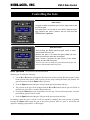
1
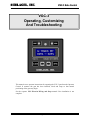
SCHLAGEL, INC.
VGC-3 Gate Control
VGC-3
Operating, Customizing
And Troubleshooting
This manual covers operator instructions for operating the VGC-3 gate from the Operator
Control. It assumes the gate has been installed, wired and setup so that normal
positioning of the gate may begin.
See the separate VGC Electrical Wiring and Setup manual if the installation is not
complete.
Page 1
SCHLAGEL, INC.
VGC-3 Gate Control
VGC Control Layout
10
1
9
2
8
3
7
4
6
5
The diagram above shows the function of the controls and the meaning of the text shown in the LCD
display.
1.
2.
3.
4.
5.
6.
7.
8.
9.
10.
The MENU button allows access to all of the options, functions and settings described on page 5.
2 line LCD information screen.
The right number on the second line of the display shows the current percent opening of the gate.
When the gate is closed the OPEN button opens the gate to the request setting on the left side of
line 2 (#7). It has no operational function once the gate is open.
The arrow keys adjust the requested position (#7). If the gate is closed this is only the preset and
no gate movement takes place. If the gate is not closed, the gate will follow the arrow keys
requested position.
The CLOSE button will immediately close the gate from any open position. The gate will not
open again until the OPEN button is pressed, regardless of the arrow key setting.
The left number on the second line of the display shows the requested position for the gate.
The top line of the display presents the gate name. It is always shown during normal operation.
The user can program a gate name up to 9 characters long to replace the default name ‘VGC
GATE’. If the UIO interface is used for PLC communication, the network address character (G:)
is shown before the gate name. The network address is field programmable.
The RESET key re-boots the microprocessor.
The muti-colored LED is green when the gate is closed, red when it is not closed and yellow
when the gate is being controlled by automation.
Page 2
SCHLAGEL, INC.
VGC-3 Gate Control
Controlling the Gate
Gate Closed
The gate is closed. Its position (line 2 on the right) is 000% and
the LED is green.
The preset (line 2 on the left) is set to 025% using the arrow
keys. Because the gate is closed it will not move until the
OPEN button is pressed.
Gate Not Closed
After pressing the OPEN button the gate moves to 025%
open and the LED turns red.
Because the gate is not closed the gate position will now
follow the arrow keys when they are pressed.
When CLOSE is pressed the gate moves to the closed
position and the LED turns green..
The arrow keys can now change the preset number but the gate will
not move until the OPEN button is pressed.
Basic operation – No Network or Network Released
With the gate closed do the following:
Use the or buttons to change the desired percent of gate opening. Because the gate is at the
home position (fully closed - LED is green), you are just pre-setting the future gate position. The
gate will not move until the Open button is pressed.
Press the Open button and the gate will open to the preset percentage and stop.
The position of the gate can be changed with the and buttons and the gate will follow to
meet the new value after 1 second of button inactivity.
Pressing the Close button will immediately close the gate. The last selected position is now the
preset but the gate will remain closed.
Press the Open button and the gate will open to the preset position and stop.
In summary, when the gate is closed, it will not respond to changing the preset percent of opening.
Pressing the Open button opens the gate to the preset position. Once it’s open, it will follow the
operator’s changing request until it is closed again.
Page 3
SCHLAGEL, INC.
VGC-3 Gate Control
Basic operation – With Network Control
If the gate is being controlled by a PLC the operator’s buttons are disabled. The PLC must release control
before the operator can use the terminal.
In the special case of an operating problem that results in an error the PLC automatically looses control
and the terminal is set to ‘Manual Mode’ so the operator can do what is necessary to clear a jam etc. Once
‘Manual Mode’ is closed (pressing the Close button) the PLC will immediately assume control.
Gate Jams and Error Handling
Gates can operate in difficult environments and handle challenging material. There must be a procedure
available to the operator to deal with the unexpected obstructions and seizures that may occur. The VGC3
will attempt to deal with the problem before handing the problem over to the operator.
When it detects a jam (loss of sensor activity when the motor is running), it stops, backs up a bit and
retries forward movement to see if it can break loose or dislodge an obstruction. If it is successful, it
continues to its destination. If not, it tries two more times to clear the problem. If that fails the LED will
show a fast blink, a ‘FATAL ERROR’ is displayed and the control enters ‘Manual Mode’ (see below).
When the obstruction has been manually cleared, the operator should make sure the gate is closed and the
LED is green, then press the Close button.
Power Loss
If the VGC3 suffers a power loss, or the Reset button is pressed, the control looses its home reference.
When it regains power it does not attempt to move the gate but intermittently flashes a ‘CLOSE GATE’
message on the bottom line of the display. If the operator knows that the gate position was not changed
during the power loss and wants to continue with the state of the gate as is, there is no negative
consequence except that the position of the gate cannot be changed until it has been temporarily closed to
regain its home reference.
Page 4
SCHLAGEL, INC.
VGC-3 Gate Control
Menu System and Configuration
When the gate is closed the Menu button is enabled. A password is required to gain access to this
function. Press and hold the key until the value 123 is displayed, then press the Open button.
Pressing the and buttons will display the menu options in ‘round robin’ fashion. The options
available are:
Exit
AutoRun
Net Address
Gate Name
Install Gate
Manual Mode
Operation
Service
Duty Check
When the desired option is shown, press the Open button to access the function. Pressing the Close
button at this point returns the control to normal operation.
A summary of each option follows:
Exit – Escape function
Close the Menu and return to normal operation. Most functions will automatically return to normal when
you complete them.
AutoRun* – Diagnostic function
Exercises the gate by continuously moving the gate to different random positions. It will continue to run
in this mode until the Close button is pressed or power is interrupted.
Net Address – Network Setup
Enables network communication by selecting a character for the address. Setting this character to a blank
disables the network for this control.
Gate Name – Customizing the display
A custom gate name up to 9 characters long can be entered to display on the top line replacing the default
‘VGC GATE’ name.
The characters to select from are 0123456789 ABCDEFGHIJKLMNOPQRSTUVWXYZ.
Choose each character with the and keys and select it with the Open button. Press the Close
button when finished.
Install Gate * – Install the gate.
Runs the automatic install routine to detect, and correct if necessary, the motor rotational direction and the
fully open and fully closed gate positions.
Manual Mode* – Diagnostic function
Allows the operator to manually run the gate motor in either direction using the and buttons. Press
Close to exit Manual Mode and return to normal operation.
Operation – Select operating mode.
You may select the normal ‘VARIABLE’ operation or ‘OPEN/CLOSE’ operation when the gate should only
be fully open or fully closed (e.g. an intermediate gate on a conveyor).
Page 5
SCHLAGEL, INC.
VGC-3 Gate Control
Service – Manual settings
Allows the operator to manually change the gate parameters detected during the ‘Learn Mode’ routine. A
password is required to gain access to this function. Press and hold the key until the value 123 is
displayed, then press the Open button. You may then change the fully-open wheel count and the motor
direction (0 or 1).
Duty Check* – Diagnostic function
Check the adjustment of the wheel sensor. This number should be between 00% and 70%. The second
number shown is the number of increments to a full open position.
* Caution! The gate will move when these options are selected.
Troubleshooting
A VGC system consists of the VGC Operator Control, a motor power module and a barrier relay. These
may be located in remote areas of the facility. Determining the cause of the problem may require attention
to any or all of these areas. The two most common problems are the loss or interruption of power or a
mechanical problem at the gate.
The error message on the display is helpful in resolving the problem.
Fatal Error - Three attempts were made to move the gate but were unsuccessful. Most likely this
is caused by mechanical interference in the gate but could also be an improperly adjusted wheel
sensor on the gear reducer.
Closing Error - This happens after the CLOSE switch has been pressed, or the power is restored,
but the gate was unable to find the closed position. This too is usually caused by mechanical
interference in the gate but it may also be that the gate closed sensor is improperly adjusted.
Press the CLOSE switch when ready to try again.
It may be helpful to manually move the gate back and forth for testing and inspection. Do this by using
the Control Menu to select Manual Mode. The gate may then be intermittently moved using the arrow
pushbuttons.
If the display is lit but it is blank, there may have been a severe power disruption and just powering up the
control may fix the problem. Remember that after a reset or restoration of power the gate home position is
lost. The gate will not respond to any move command except CLOSE, which will reset its position
memory..
If that does not fix the problem a qualified maintenance person should look at the gate drive and sensors.
Sensor adjustment and associated testing is discussed in the installation manual.
Page 6
SCHLAGEL, INC.
VGC-3 Gate Control
The following three modes of gate operation are configured using the Menu system on the VGC
control.
VARIABLE Mode Operation
The default operation. The gate may be opened between 0% and 100% as set by the or keys.
OPEN-CLOSE Mode Operation
The gate does not allow for positioning anywhere between 0 and 100%, effectively eliminating the use of
the or keys on the control. Commonly used on 2-way valves or intermediate discharges on
conveyors.
RELAY MODE Operation
VGC Relay Mode is used when opening and closing of the gate is performed by an external users relay
and the open position is determined by the setting of the VGC control preset value.
A pair of wires is run from terminals 1 and 5 of the 6 position screw terminal on the VGC control to the
N.O. contact of the customer relay (see diagram below). Do not apply power to these terminals. JP1
must have a solder bridge.
When this contact is open the gate will close and remain closed.
When the relay contact closes, the gate will open to the position set by the VGC preset number. The gate
will follow the arrow key changes to the request number as long as the relay contact remains closed.
When the relay contact opens, the gate will close. The setting of the preset value may be changed at this
time but the gate will not open to the preset position until the relay contact closes again.
If it is desired to also run the gate manually from the VGC control, the optional customer supplied toggle
switch may be installed as shown in the figure below. When this toggle switch is closed, the gate may be
set to any position, including fully closed, by using the VGC arrow keys. The rest of the VGC buttons are
disabled and not used in this mode.
The wiring between the customer relay and the VGC
control should be 24 ga. or heaver. Please contact our
technical support group when a wire length greater
than 50’ is required.
Important: Relay Mode must be turned on after
gate installation using the VGC Menu and setting
the network address to the special character “#”.
See the Control Menu section in this manual for
setting the network address.
Page 7
SCHLAGEL, INC.
VGC-3 Gate Control
Network Operation
Network interfacing for PLC control of the VGC gate is covered in other manuals as referenced on the
front cover of this manual. The intent of this section is only to cover the influence of the PLC on the VGC
Control from the gate operator’s standpoint.
When the PLC is only monitoring the gate, the gate operator can use the gate at will as explained in detail
in this manual. The operator will have no indication that the PLC is monitoring the VGC gate.
Once the PLC takes control of the VGC the story changes. The LED, which up to this point was red or
green, now turns orange indicating PLC now has control. The operator can see all moves performed by
the PLC but is unable to change the position of the gate.
Consult with your PLC integrator to understand how and when control should be transferred.
VGC Specifications
VGC Drive Components
Motor
.5 HP, 1750 RPM, 220 Volt 3 Phase 56 C-Face
Gear Reducer
100:1 worm gear, 1” dia. adjustable clutch driven output shaft
Inverter input
120 Volt, single phase. Full load current draw 9.6 Amp
Gate Speed - Direct Shaft Drive, 11 Tooth Pinion
Gate travel speed
2.4 In/Sec (1)
Gate force
Adjustable 0 to 1800 Lbs. (See Note.)
Travel
1 inch to over 100 ft.
Operator Control Panel
Size
3” x 3” x 1” deep
Power
Supplied by the inverter within 10 wire ribbon control cable
Display
12 character, 2 line LCD, Multicolored LED
Operator
Multi-button operator’s control in NEMA 12 enclosure
.Operating Temp.
0° - 100° F Tested range. (2)
Note: 1 Roller chain reductions may be used to increase force at the cost of speed.
2 LCD screen update slows down below 32° F although gate operation is not
Schlagel, Inc., Cambridge Mn 55008
800-328-8002 or 763-689-5991 Fax 763-689-5310
www.schlagel.com [email protected]
Page 8
affected.