1
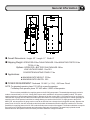
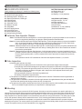
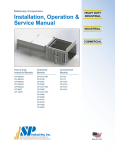
OWNER'S MANUAL MODEL SL505 RESIDENTIAL SLIDE GATE OPERATORS SL505 GATE OPERATORS ARE FOR USE ON VEHICULAR PASSAGES ONLY AND NOT INTENDED FOR USE ON PEDESTRIAN PASSAGE GATES. 2 YEAR WARRANTY Serial # _____________________ (located on electrical box cover) Installation Date:_______________ 1 Contents Page General Information...........................................................................................................3-4 Features...............................................................................................................................5-6 Parts Identification..............................................................................................................7-8 Installation.........................................................................................................................9-11 Electrical..........................................................................................................................12-16 Fine Tuning.......................................................................................................................16 Master/Second........................................................................................................................17 Wiring Diagrams..............................................................................................................18-20 Safety Edge and Safety Warning Placard Installation....................................................21 Options............................................................................................................................22,23 Maintenance & Safety........................................................................................................24 Troubleshooting...............................................................................................................25-27 Notes......................................................................................................................................28, 29 IMPORTANT SAFETY INSTRUCTIONS WARNING - To reduce the risk of injury or death: 1) READ AND FOLLOW ALL INSTRUCTIONS 2) Never let children operate or play with gate controls. Keep the remote control away from children. 3) Always keep people and objects away from the gate. NO ONE SHOULD CROSS THE PATH OF THE MOVING GATE. 4) Test the gate operator monthly. The gate MUST reverse on contact with a rigid object or stop when an object activates the non-contact sensors. After adjusting the force or the limit of travel, re-test the gate operator. Failure to adjust and re-test the gate operator properly can increase the risk of injury or death. 5) Use the emergency release only when the gate is not moving. 6) KEEP GATES PROPERLY MAINTAINED. Read the owner's manual. Have a qualified service person make repairs to gate hardware. 7) The entrance is for vehicles only. Pedestrians must use separate entrance. 8) SAVE THESE INSTRUCTIONS. 2 General Information Overall Dimensions: Height: 23" Length: 11" Width: 8" Shipping Weight: OPERATOR:53 lbs CHAIN PACKAGE:12 lbs MOUNTING POSTS:16 lbs TOTAL: 81 lbs Options: OPERATOR + BATTERY RUN PACKAGE: 59 lbs LOW VOLTAGE CABLE: 1 lbs/10 ft CONCRETE MOUNTING STAND: 17 lbs Applications: z MAXIMUM GATE WEIGHT: 375 lbs z MAXIMUM GATE LENGTH: 20 ft POWER REQUIREMENT: Dedicated 115 VAC (+/- 10V) , 5A Power Circuit NOTE: For standard operator, place 115 VAC at or near the operator. For Battery Run operator, place 115 VAC within 1,000 ft of the operator. There are three possibilities for supplying power to the SL 505 gate operator. The standard power supply version is made to connect directly to 115 Volt, 5 Amp power source and is available for full systems capability models. This power supply must be at or near the gate operator location. Because of the low current draw, 115 Volt power may be run as far as 1000 feet with 12 gauge wire from the main breaker panel and can be run much farther with larger wire. Another possibility for supplying power to the operator is with the low voltage battery run version of the SL 505. To supply power to the SL 505 battery run, wire as small as 16 gauge can be run as far as 300 feet from a charger that is plugged in remotely. Because the power is low 12 Volt DC, the wire can be direct burial wire which eliminates the need for expensive conduit runs. The other possibility for supplying power to the SL 505 is with the Solar power version of the operator. The Solar model does not require any power to be run because the operator and solar power supply are self contained. The panel may be placed several hundred feet from the operator if this is necessary to achieve maximum sunlight conditions. 3 General Information INCLUDED WITH OPERATOR: Check package to make sure it contains the following items. STANDARD GATE OPENER z 1-Model SL 505 gate operator z 2-Mounting Posts 2" Diameter x 30" z 2-Gate/Chain Brackets, U-Bolt type z 2-U-Bolts Round z 2-U-Bolts Square z 1-Chain #40 x 25 ft z 2-Master Links #40 z 2-Chain Bolts z 2-Self Tapping Screws z 1-Hex Key for Cover z 2-Manual Release Keys z 2-Safety Warning Placards BATTERY RUN ONLY (OPTIONAL) z 1-Burial cable, 10 ft z 1-Charger, 12 Volt z 1-Battery, 12 Volt (installed) SOLAR ONLY (OPTIONAL) z 3-Pipe sections, 1" X 24" z 2-Pipe couplings, 1" z 1-Solar Panel Assembly z 5-Lock Rings z 2-Batteries, 12 Volt (installed) (See parts identification.) Vehicular Gate Operator Classes: Class I - Residential Vehicular Gate Operator: A vehicular gate operator (or system) intended for use in a home of one-to four single family dwellings, or a garage or parking area associated therewith. Class II - Commercial/General Access Vehicular Gate Operator: A vehicular gate operator (or system) intended for use in a commercial location or building such as a multi-family housing unit (five or more single family units), hotel, garage, retail store, or other building servicing the general public. Class III - Industrial/Limited Access Vehicular Gate Operator: A vehicular gate operator (or system) intended for use in an industrial location or building such as a factory or loading dock area or other locations not intended to service the general public. Class IV - Restricted Access Vehicular Gate Operator: A vehicular gate operator (or system) intended for use in a guarded industrial location or building such as an airport security area or other restricted access location not servicing the general public, in which unauthorized access is prevented via supervision by security personnel. Gate Operator model SL 505 is intended for Vehicular Gate Operator Classes I, II, III, and IV. Gate Inspection: a) Install the gate operator only when: 1) The operator is appropriate for the construction of the gate and the usage Class of the gate, 2) All openings of a horizontal slide gate are guarded or screened from the bottom of the gate to a minimum of 4 feet (1.2 m) above the ground to prevent a 2-1/4 inch (57.15 mm) diameter sphere from passing through the openings anywhere in the gate, and in that portion of the adjacent fence that the gate covers in the open position. 3) All exposed pinch points are eliminated or guarded, and 4) Guarding is supplied for exposed rollers. b) The operator is intended for installation only on gates used for vehicles. Pedestrians must be supplied with a separate access opening. c) The gate must be installed in a location so that enough clearance is supplied between the gate and adjacent structures then opening and closing to reduce the risk of entrapment. d) The gate must be properly installed and work freely in both directions prior to the installation of the gate operator. Do not over-adjust the gate sensitivity to compensate for a damaged gate. Mounting: There are two ways to mount the SL 505 operator. One way to mount the operator is to attach it with bolts to a concrete surface using the optional concrete mounting stand and sleeve anchors. In some cases there will already be an existing concrete surface or pad available to bolt the operator to. If there is no existing concrete surface or pad, it is very easy to fashion one so that the operator can be bolted down at a later time using sleeve anchors. The other way to mount the SL 505 operator is directly into the earth with the two 2" X 30" mounting posts that have been provided. For this installation the posts are attached to the operator, one post hole is made in the earth and then the operator with posts attached is set in place. The cement can then be poured into the post hole and will dry within minutes if concrete accelerator is used. The operator can be put into full operation the very same day. 4 Features FULL SYSTEMS CAPABILITY Sensitivity As with other LiftMaster gate openers, the SL 505 has a built-in safety feature which when adjusted properly will deliver only enough power to the motor to overcome the resistance of the gate. What this means is that if the gate runs into a vehicle or pedestrian, the gate will immediately stop or reverse. Because of the DC motor technology incorporated into the SL 505, the sensitivity feature is much more sensitive and is at least 50% more effective than traditional AC current sensors. Soft Start/Soft Stop A unique feature of the SL 505 is the Soft Start/Soft Stop feature. Traditional gate openers will begin opening the gate with full power causing a yanking or jerking effect that severely decreases the life of mechanical parts. The SL 505 will begin opening or closing the gate very slowly and will then increase to full speed. This creates a very gentle gate transition which considerably reduces the amount of wear and tear on all mechanical parts. Manual Release Key Switch This simple on-off key switch is built into the side of the operator. In an emergency, even with the power off, the gate can be pushed open manually after turning the key counter-clockwise. Electronic Brake Traditional gate openers typically have a mechanical brake or clutch which requires special maintenance. The DC motor technology that is incorporated into the SL 505 provides the gate opener with a brake that will never wear out. This patented feature causes the gate to come to a stop and keeps the gate locked when stopped in any position. Battery Run/Low Voltage (Optional) The SL 505 is available in both battery run and solar versions. The main and most obvious benefit to having battery run or solar is the ability to open and close the gate even when there is no power. This in itself provides an extremely high level of convenience. If there is a power failure the gate will operate as it normally does and can be opened up to 150 times before power is restored. Another very important benefit to having battery run is that it is not necessary to have 115 Volts at the operator location because running high voltage is typically very expensive and highly regulated. All that is needed to supply power to a battery run version of the SL 505 is some inexpensive low voltage burial cable. If the cable is 16 gauge it can be run as far as 300 feet. For solar versions of the SL 505, no power needs to be run to the operator. The solar version has a solar panel which is normally attached to the gate opener but can placed anywhere that allows the panel to receive maximum sunlight. Visual Feedback The SL 505 Full Systems Capability circuit board has been equipped with visual feedback LEDs (small indicator lights) to help simplify installation and troubleshooting. There are LEDs located directly beside each input terminal to indicate if any input devices are active. There are also two LEDs which indicate that the circuit board is delivering power to the motor and are labeled O and C for either the Opening or Closing directions of travel respectively. Collectively, all of the LEDs combined provide quick glance information to the installer or service technician showing visually what is happening in the normally invisible operation of the circuit board. 5 Features continued... Auto Close Timer The operator comes factory preset with the auto close timer function OFF. The auto close timer will close the gate automatically after a specific amount of time has elapsed. The amount of time can be easily adjusted between 0 and 45 seconds by turning a small "pot" located on the edge of the circuit board (See page 17). The timer can be disabled or activated by flipping a single switch located on the top edge of the circuit board. If the timer will be used it is recommended that some type of supplementary safety device (loops, photo beam etc.) be installed. Gate Sensitivity Adjustment The amount of force necessary to stop the gate can be adjusted to conform to the various sizes and weights of any particular gate. The full systems capability circuit board provides separate adjustments for both the opening and closing direction. When adjusting the sensitivity, the operator can be given only as much energy as is necessary to overcome the resistance of the gate. If the gate should strike an obstruction either direction, the gate will reverse. If the gate should again strike an obstruction before reaching a limit, the gate will stop and remain stopped. (See page 17) Master And Second Some very large entrances may require the use of two gates. If this is the case, the two gates can be easily automated using the "Master and Second" configuration. This configuration uses two gates and two operators in ONE driveway. The Full systems capability models have terminals provided especially for Master and Second applications and will reliably operate simultaneously all of the time. Pulse Open Input The Pulse Open input feature is an open input on the circuit board which will increase the security of the SL 505 gate operator system. When an open input device such as a key switch is connected to the Pulse Open input, and the device is activated, the gate operator will activate but will then ignore the input if the input is prolonged. What is significant about this feature is that there is the possibility of a device being stuck and if the device is connected to the standard open input the gate will be held open. If the device is connected to the Pulse Open input on terminals 6 and 7, the circuit board will ignore the stuck input and will allow the gate to close. For added security any open input device may be used with Pulse Open including push buttons, key switches, numerical key pads etc. Peripherals POWER SUPPLY: There is 12 Volts DC .1 AMP available on the circuit board which is used to supply power to a radio receiver or other device. OPEN INPUT: Normally open devices are connected to terminals 5 and 6 on the circuit board to cause the gate to open and/or close in PUSH-TO-OPEN/PUSH-TO-CLOSE (Timer switch OFF) mode of operation. Normally open devices are connected to terminals 5 and 6 to cause the gate to open in AUTO CLOSE TIMER (Timer switch ON) mode of operation. In this mode of operation the AUTO CLOSE TIMER will automatically close the gate after a specific amount of time has elapsed. The Auto Close Timer is adjustable between 0-45 seconds. These normally open devices can be push buttons, key switches, loop detectors, photo electric beams, 24 hour timers, etc. See FEATURES on the next page for other open input capabilities. PULSE OPEN INPUT: Normally open devices are connected to terminals 6 and 7 on the circuit board to cause the gate to open. Pulse Open Input functions identical to Open Input with the exception that it will not hold open the gate. If an open device is stuck on, the gate will still close. This feature is sometimes used to provide a higher level of security but should be used only in addition to another open device connected to Open Input so the gate can still be opened if necessary. SAFETY INPUT: Normally open devices are connected to terminals 4 and 6 on the SL 505 circuit board to cause the gate operator to open and/or hold the gate open in any position except the fully closed position. Normally open safety input devices that can be used are push buttons, radio receivers, key switches, loop detectors, photo electric beams, 24 hour timers, etc. N.C. STOP INPUT: Normally closed devices are connected to terminals 8 and 9 on the circuit board after removing the stop jumper that is on terminals 8 and 9. The N.C. Stop Input will cause the gate to stop at any position and will remain stopped until activated to open or close. N.O. STOP INPUT: Normally open devices are connected to terminals 9 and 11 to cause the gate to stop in any position until the gate is again activated to open or close. N.O. Stop Input functions identical to N.C. Stop input with the exception that it requires normally open contacts instead of normally closed contacts. CLOSE INPUT: Normally open devices are connected to terminals 9 and 10 on the circuit board to cause the gate operator to close the gate when in any position. Normally open input devices that can be used are push buttons, radio receivers, key switches, loop detectors, photo electric beams, 24 hour timers, etc. 6 Parts Identification 7 Parts Identification continued... K75-40047 SERVICE KIT K74-40041 SERVICE KIT A MOTOR REDUCER ASSEMBLY F OPERATOR COVER DESCRIPTION QTY DESCRIPTION QTY LIMIT NUT 2 COVER, SL505 MOTOR,REDUCER, 12 VOLT DC 1 LABEL, BUBBLE, 4" X 2" 1 HEX BOLT, 3/8-16 X 3/4" 3 1 1 1 1 FLATWASHER, 3/8" 3 SCREW, SOCKET, 3/8-16 X 1" FLATWASHER, 3/8" LOCKWASHER, 3/8" 3 WASHER, 5/16, INTERNAL GRIP, PLASTIC K74-40084 SERVICE KIT K74-40032 SERVICE KIT SOLAR PANEL (OPTIONAL) B BRIDGE RECTIFIER DESCRIPTION QTY G DESCRIPTION QTY CAPACITOR, RECTIFIER 1 SOLAR BRACKET 1 BRIDGE RECTIFIER 1 SOLAR PANEL, 12V, 5 Watt 1 SCREW, PH PHILLIPS, #6-32 X 1" FLANGE NUT, 6-32 1 1 MODULAR CONNECT, SP, WHITE 1 MODULAR CONNECT, SP, YELLOW 1 SCREW, PH PHILLIPS, #8-32 X 5/8" 2 K74-40045 SERVICE KIT C PCB GUARD AND STANDOFF DESCRIPTION QTY SCREW, PH PHILLIPS, #1/4-20 X 5/8" 2 FLANGE NUT, 8-32 2 FALNGE NUT, 1/4-20 2 GUARD, PCB 1 JUMPER, PCB 3 HEX STANDOFF, 6-32 x 1", M/F 4 HEX STANDOFF, 6-32 x 1/2", F/F 4 SCREW, PH PHILLIPS, #6-32 X 1/4" 4 LIMIT SWITCH 2 SCREW, PH PHILLIPS, #6-32 X 3/8" 4 RUBBER GROMMET, 7/16" DIA.x 1/16" 1 SCREW, PH PHILLIPS, #4-40 X 5/8" 4 D SCREW, PH PHILLIPS, #8-32 X 5/8" 2 FLANGE NUT, #8-32 2 K74-40065 SERVICE KIT EXTERNAL RESISTOR DESCRIPTION QTY K74-40044 SERVICE KIT LIMIT H LIMIT SWITCH AND PLATE DESCRIPTION QTY LIMIT ACTUATOR BRACKET 1 EXTERNAL CURRENT RESISTOR 1 LOCKNUT, #8-32 2 SHRINK WRAP, 1" 2 SCREW, PH PHILLIPS, #8-32 X 1" 2 SCREW, PH PHILLIPS, #2-56 X 1/2" 2 SPRING, LIMIT PLATE 2 LOCKNUT, #2-56 2 WIRE, GREEN, 8", STIP X FORK 1 WIRE, YELLOW, 8", STIP X FORK 1 K75-40068 SERVICE KIT E IDLER SPROCKET DESCRIPTION QTY K74-19915 RADIO / BATTERYSERVICE KIT I DESCRIPTION QTY BOX 1 STRAP 1 RECEIVER 1 SPROCKET, 41B14, 3/16" KW, (2) 1/4" SS 1 90 DEGREE ANTENNA 1 BEARING, 1/2" ID x 3/4" OD x 1/2" 1 12 V DC BATTERY 2 HEX BOLT, 5/8-11 X 2-3/4", GRADE 5 1 #8 NUT 3 HEX JAM NUT, 5/8-11 2 COVER 1 LOCKWASHER, 5/8 1 SCREW 2 INDIVIDUAL PARTS ITEM PART # DESCRIPTION QTY 1 13-40067 LIMIT NUT 2 2 02-40075 KEY RELEASE SWITCH, 10A, SPST 1 3 15-41B11CCB 21-40074 SPROCKET, 41B11, ½" BORE, ½ KW, 2SS 1 XFMR, 120V, 60HV 1 4 5 23-40050 LIMIT SWITCH 2 6 25-40083 OVERLOAD, 1.5 AMP 1 7 28-40029 PIPE, 1" NPT X 24" 2 8 29-40071 RESISTOR, 1 OHM, 25W, OHMITE 1 9 29-40089 SONALERT PIEZO ALARM 1 10 29-40095 CHARGER, BATTERY 12V.5A DUAL STG 1 11 29-NP712 81-40034 BATTERY, 12V 7AH 2 MODULAR CONNECT, SP, WHITE 1 MODULAR CONNECT, SP, YELLOW PCB, COMPLETE, FULL SYSTEM 1 1 17 81-40035 K79-40056 K79-40091 PCB, COMPLETE, SL505-BR 1 18 K79-40098 PCB, COMPLETE, SOLAR 1 19 25-2015 OVERLOAD, 15AMP 1 14 15 16 8 Installation 1 The tail end of the gate should extend approximately 18 inches beyond the edge of the driveway. If this is not the case, an extension tail will need to be added to the gate. This will give room for the gate operator. Make the extension tail 18" X 18" as shown. If the gate has not yet been fabricated, add 18" to the length of the gate. 2 Remove the gate operator from it's package and make sure that all parts are included. Refer to General Information and Parts Identification. If the gate operator will be post mounted, insert the two supplied mounting posts into the bottom of the gate operator and through the u-bolts. The posts should insert 5 inches into the operator. Firmly tighten the u-bolt nuts to securely fasten the posts. 3 Refer to figure 3 to determine the operator location and dig a post hole approximately 25 inches deep or more. Set the operator with posts attached into the post hole and fill the hole with cement. While the concrete is setting, recheck the position of the gate operator so that it is positioned as in figure 3 at left. 9 Installation Continued... ALTERNATIVE 4 If it is preferable to mount the gate operator onto a cement pad, form a cement pad that is 14" by 16" as shown in figure 4 at left. For this installation, an optional concrete mounting stand is required. The cement pad should be at least 6" deep or below the frost line, and may protrude above the ground 4" or more as shown if it is desirable to elevate the gate operator. Elevating the gate operator may prevent unnecessary flood damage in places where the drainage is not adequate. 5 Place the operator on the optional concrete mounting stand by inserting the vertical pipes up through the bottom of the gate operator and through the u-bolts. Tighten the u-bolt nuts firmly to secure the concrete mounting stand to the gate operator. Place the operator with stand onto the cement pad and position it as shown in figure 5 at left. Drill through the four corner holes of the stand and into the cement pad using a 3/8" masonry bit. The holes should be at least 3-1/2" deep. Drive 3/8" sleeve anchors into the holes and tighten firmly. ALTERNATIVE 6 The chain may be threaded through the sprockets in one of two ways as shown at left and the choice is simply a matter of preference. Threading the chain one way will make the chain low as it extends across the driveway and the other way will make it higher. The side plates may be moved up or down by loosening the nuts which secure them, moving the plate to it's alternate position, then re-tightening the nuts. 10 Installation continued... 7 CHAIN BOLT GATE BRACKET MASTER LINK U-BOLT SELF TAPPING SCREW 8 RELEASE KEY SWITCH TO PUSH GATE MANUALLY The ends of the chain are attached to each end of the gate by using the gate brackets and chain bolts as shown at left. If the gate frame is 2" X 2" square tube, the gate brackets may bolted to the gate using the square u-bolts as shown. For round tubular frames, use the supplied round u-bolts for attaching the brackets. In this case use the self tapping screw which prevents the bracket from shifting. For irregular sized gate frames, the gate brackets should be welded to the gate. Attach the chain ends with master links and tension the chain by tightening the chain bolt nuts. The limits of travel determine where the gate stops in both the open and closed positions. These limits may be adjusted very closely without any power to the gate operator. Before making these adjustments, the gate operator may be put into manual release by turning the manual release key switch as shown at left. This allows the gate to be pushed manually in either direction. Be careful not to run the limit nuts past the limit switches as this may cause damage to the switches. DO NOT ADJUST THE LIMITS WHILE THE POWER IS ON 9 TURN NUTS TO ADJUST LIMITS PUSH DOWN TO ADJUST LIMITS 11 The limits of travel are adjusted by positioning the limit nuts against the limit switches (pressing in the switch) while the gate is open or closed. To adjust the limit nuts, first push down on the limit nut guide plate. This allows the limit nuts to be freely spun up or down the screw. One limit nut should press in one limit switch when the gate is open, and the other nut should press in the other switch when the gate is closed. When finished, be sure that the limit guide plate firmly engages both limit nuts. Electrical 1 Before making any electrical connections be sure that the power is switched off. If the gate operator is a standard 115 Volt model, run conduit from the 115 Volt power source into the gate operator. The gate operator is provided with a 90 degree flexible conduit fitting for installations where the electrical box is relatively close. Because of the 90 degree fitting, it is generally easier to run the electrical wires through the flexible conduit before attaching the conduit. Wiring for other devices such as push buttons may also be run at this time either in the same conduit or in another. Make sure that wiring is employed as required by local codes. If not already done, run three 12 gauge wires (hot, neutral, and ground) from the power source, through the conduit and into the gate operator. It is easiest to run these wires back out of the large hole in the operator along with the three existing wires. This allows the connections to be made externally and then later inserted back into the operator through the large hole. Be sure to use wire nuts to secure these connections. Be sure that the grounding wire is connected to a good earth ground. Make the connections as follows: Black to (hot) White to (neutral) Green to (ground) 2 3 If the gate operator is a battery run model, it is packaged from the factory with the battery disconnected. Connect the red wire to the positive battery terminal and the black wire to the negative battery terminal. There are wires provided for connecting the low voltage burial cable from the float charger to the gate operator. The burial cable may be run through the knock-out in the bottom of the battery enclosure and then connected to the two wires provided. Be sure that the positive and negative match the positive and negative of the charger. 12 Electrical continued... 4 Connect the other end of the burial cable from the operator to the float charger. Be sure to match the positive and negative terminals of the charger to the positive and negative terminals of the battery. Once the connections are made, plug the charger into a 115 Volt outlet. If possible, it is desirable to locate the charger out of the weather. Let the charger charge the battery for a couple of hours before putting into operation. 5 If the gate operator is solar powered, no power will need to be run into the machine. The solar panel is set up to be attached to the gate operator and extension pipes are provided to elevate the panel up above the operator. While assembling the pipes and attaching the panel, run the wires from the panel through the pipes. The ends of the wires are provided with connectors which can simply be plugged in. Turn the panel so that it will get maximum sunlight during the day. If necessary the panel may be mounted away from the gate operator to get it out of the shade and into more consistent sunlight. 6 Similarly to the battery run, the solar operator comes with the battery wires disconnected. For both batteries, connect the black wires to the negative terminals and the red wires to the positive terminals. The wires have been labeled to make these connections easier to do. 13 ACCESSORY CONNECTIONS - FULL SYSTEMS CAPABILITY Electrical continued... 412 HM RADIO RECEIVER 4 3 2 1 TO AVOID POSSIBLE INJURY OR DAMAGE TO EQUIPMENT DO NOT MAKE ELECTRICAL CONNECTIONS WHILE POWER IS ON SAFETY NOTES: Controls must be far enough from the gate so that the user is prevented from coming in contact with the gate while operating the controls. Controls intended to be used to reset an operator after 2 sequential activations of the entrapment protection device or devices must be located in the line of sight of the gate. Outdoor or easily accessible controls shall have a security feature to prevent unauthorized use. OPEN INPUT: Any device that is used to open the gate from a closed position is an open input device. The device used must provide normally open contacts. These normally open contacts are connected to terminals 5 and 6. These open input terminals will cause the gate operator to open and/or close if the timer switch is in the OFF position. If the timer switch is in the ON position, these open input terminals will cause the gate operator to open and will hold the gate open until the input is released and the hold open time has elapsed. CLOSE INPUT: Any device that is used to close the gate is a close input device. The device used must provide normally open contacts. These normally open contacts are connected to terminals 9 and 10. These close input terminals will cause the gate operator to close the gate any time the gate is in a non-closed position and can be used to override the timer and close the gate prematurely. N.C. STOP INPUT: Any device that is used to stop the gate operator while it is running in the open or closed directions is a stop input device. These stop input devices must provide normally closed contacts. To connect these normally closed contacts, remove the stop jumper from terminals 8 and 9 and then connect the contacts to these same terminals 8 and 9. 14 N.O. STOP INPUT: This input functions the same as the N.C. Stop, with the exception that it requires normally open contacts. These contacts are connected to terminals 9 and 11. SAFETY INPUT: Any device that is used to open and/or hold open the gate while the gate is in a non-closed position is a safety input device. The safety input device must provide normally open contacts. These contacts are connected to terminals 4 and 6. This function is especially useful when the auto close timer is being used in preventing the gate from accidentally closing on a pedestrian or vehicle. PULSE OPEN INPUT: This input functions similarly to the standard open input with the exception that it will not hold the gate open if the input remains present. This feature will add additional security to the gate operator system in the event that there is a device that is stuck on. Pulse open is found at terminals 6 and 7. OTHER COMMON ACCESSORIES Electrical continued... Be sure to read this entire manual before attempting to perform any type of installation or service to the gate opener. Once the installation has been completed, this installation and service manual becomes the property of the home owner or end user and should be given to the new owner at that time. For a personal copy of this manual, please contact a LiftMaster. NOTE: z All open and safety devices must have normally open contacts. z For Devices requiring power, refer to the specific diagram for that particular device. 15 Fine Tuning This step is for sensitivity adjustments on the full systems capability control board. To make adjustments, use a small screw driver to turn the adjustment "pots" clockwise for more sensitivity or counter clockwise for less sensitivity. There are separate adjustments for both the opening and closing directions of travel and these must both be adjusted. Try applying force against the gate while it is moving both open and close to test the setting (Caution: Do not stand directly in the path of the gate while doing this). The gate should stop or reverse easily. Caution: Disconnect power while making any adjustments. 1 With the full systems capability control board there is the option of using the auto close timer which will close the gate automatically after it has opened. To turn this feature on, flip the auto close timer to the on position. To adjust the amount of time it takes for the gate to begin closing use a small screw driver to turn the adjustment "pot" clockwise for more time (45 sec max) or counter clockwise for less time. It is recommended that if the auto close timer function is used, that there be additional safety equipment installed to prevent the gate from closing into a vehicle or pedestrian. Caution: Disconnect power while making adjustments. 2 3 FULL SYSTEMS CAPABILITY 16 If the gate seems to be functioning in reverse, the right/left side operation switch may need to be flipped (full system capability only). One way to know if the operator is working in reverse is to try the sensitivity. If pressure is applied to the gate while it is closing, it should reverse and go open. If pressure is applied to the gate while it is opening, it should stop and remain stopped until activated again. If the gate operator responds differently than this, flip the right/left side operation switch. If the auto close timer function is turned on, this provides another way of knowing if the operator is working in reverse. If when the gate gets closed, the operator automatically opens, the right/left side switch may need to be flipped the other way. Master/Second Wiring z Connect 115 Volts AC to each SL505 gate operator. Connect the four Master/Second wires from the master circuit board to the second circuit board as shown below. Any operator can be used as either a master or a second. Accessories can be connected to the master or second operator. z Switch the Auto Close Timer switch to the OFF position on the second circuit board. The Auto Close Timer switch on the master circuit board may be switched either ON if the timer function will be used or OFF if the timer function will not be used but the second timer must always be switched OFF. z If the chain is wrapped around the sprockets in the same manner on each operator (both chains under or both chains over the drive sprocket) set the Right/Left Side Operation switch on the master circuit board to be the opposite of the way it is set on the second circuit board. If the chain wrapped around the drive sprocket on the master operator is the opposite of the way it is wrapped around on the second operator then set the Right/Left Side Operation switches the same on both operators. The Right/Left Side operation switch is located on the circuit board. If the operators are working backwards, the Right/Left Side Operation switches on both operators must be switched. The simplest way to know if the operators are working backwards is to turn the Auto Close Timer switch on the master circuit board to ON and see whether the timer works when the gate is open or closed. The timer should work only when the gate is open. Another way to know if the operators are working backwards is to try the gate sensitivity by applying pressure against the gate while the gate is opening or closing. If pressure is applied while the gate is opening it should stop. If pressure is applied while the gate is closing it should reverse and go open. If the gate responds to pressure in a way that is opposite of this then switch the Right/Left Side Operation switch on both operators. SL 505 Full Systems Capability Master Second NOTE: 1) The timer switch on the Second circuit board must be OFF at all times. 17 Wiring Diagrams SL 505 Full Systems Capability, 115 VAC 412 HM RADIO RECEIVER see pge 14 for Radio Wring Specifications 18 Wiring Diagrams SL 505 Full Systems Capability, Battery Run 412 HM RADIO RECEIVER see pge 14 for Radio Wring Specifications BREAKER 15 AMP 19 Wiring Diagrams SL 505 Full Systems Capability, Solar Powered 412 HM RADIO RECEIVER see pge 14 for Radio Wring Specifications BREAKER 15 AMP 20 Safety Edge and Safety Warning Placard Installation 1 See reversing edge sensor instructions for the exact placement of the reversing edge contact sensors. One or more contact sensors shall be located at the leading edge, trailing edge, and post mounted both inside and outside of a vehicular horizontal slide gate. When the contact sensor is hard wired, it shall be located and its wiring arranged so that the communication between the sensor and the gate operator is not subjected to mechanical damage. 2 With full systems capability control boards, the edge sensor is connected to terminals 24 and 26 as shown at left in figure 2. The gate operator is provided with two safety warning placards. The placards are to be installed on each side of the gate where they are plainly visible. The placards may be mounted using sheet metal screws through the six holes provided on each placard. All warning signs and placards must be installed where visible in the area of the gate. 21 Options 1 If it is desired that the driveway illuminate when the gate is activated, a light delay timer may be installed. The light delay timer will switch power on to the light for two minutes, then shut power back off. The timer relay is capable of switching up to 10 Amps which will handle most flood or spot lights available. A general hook-up diagram for the light and timer is shown at left. 2 The standard auto close timer built into the circuit board can be adjusted to between 0 and 45 seconds. Some installations may require that the gate must stay open for more than 45 seconds before it automatically closes. The extended auto close timer may be hooked up as shown at left. This optional timer can be adjusted to automatically close the gate after the gate has been open between 1 and 100 minutes. The extended timer will add time onto the auto close timer already on the board. For more control, reduce the timer adjustment on the main control board to zero seconds and make all adjustments with the extended auto close timer knob. 3 22 For added safety, a warning alarm may be installed in the gate operator to give audible warning that the gate is in motion. This will in some cases give extra time to get out of the way of the moving gate. The warning alarm is an ear piercing 120 decibel, dual tone, piezo siren that operates on 12 Volt DC. To install the alarm, mount the siren next to the circuit board and connect the positive wire to terminal 12 (12VDC). Connect the negative wire to limit switch 1 NC or limit switch 2 NC for the alarm to sound in the open or closed directions. Contact the manufacturer for connecting the alarm to sound in both directions. If the alarm is too loud, the sound may be partially muffled by applying tape over the two holes where the sound comes out. Options Continued... Gate Hardware Locator 23 Maintenance and Safety The SL 505 is designed to be MAINTENANCE FREE. However, for optimum performance and safety, the following maintenance procedures should be taken. Gate Sensitivity Adjustments The most important thing to maintain on any gate is the safety equipment. As the gate becomes older the amount of force necessary to move the gate will vary. When this happens, the gate sensitivity adjustments may need to be readjusted. Check to see whether the sensitivity may need adjustment at least once a month. Actuate the gate a few times and observe the amount of force that is needed to stop or reverse the gate in both directions. This can be done very easily by standing beside the gate and applying pressure with your hands against the gate while it is moving. Do not stand directly in the path of the gate while doing this experiment. The gate should stop or reverse relatively easy. If it does not stop or reverse easily or does not stop or reverse at all, make adjustments as shown on page 17 of Fine Tuning. Control Devices From time to time check to see whether all of the control devices that are connected to the operator are functioning. This is especially important of anything that was installed in regards to safety. Gate Having a well maintained gate will ensure that the operator runs smoothly and safely. Occasionally inspect the chain to see whether it is well lubricated and oil the chain if necessary. Use CHAIN AND CABLE LUBE for best results (Available from the manufacturer). Check the wheels and grease them if needed. Check the guide rollers and spray oil on their bearings. Check whether the gate appears to be operating at normal speed to determine if the gate operator may be working harder than usual to overcome friction from damaged bearings. IMPORTANT SAFETY INSTRUCTIONS WARNING - To reduce the risk of injury or death: 1) READ AND FOLLOW ALL INSTRUCTIONS 2) Never let children operate or play with gate controls. Keep the remote control away from children. 3) Always keep people and objects away from the gate. NO ONE SHOULD CROSS THE PATH OF THE MOVING GATE. 4) Test the gate operator monthly. The gate MUST reverse on contact with a rigid object or stop when an object activates the non-contact sensors. After adjusting the force or the limit of travel, re-test the gate operator. Failure to adjust and re-test the gate operator properly can increase the risk of injury or death. 5) Use the emergency release only when the gate is not moving. 6) KEEP GATES PROPERLY MAINTAINED. Read the owner's manual. Have a qualified service person make repairs to gate hardware. 7) The entrance is for vehicles only. Pedestrians must use separate entrance. 8) SAVE THESE INSTRUCTIONS. 24 Troubleshooting Transmitter Does Not Work nCheck the battery inside of the transmitter and/or try another transmitter. o Check the open push buttons or open switches if any are used. A stuck push button or any other stuck opening device connected to terminals 4 and 5 will cause the operator to lock up. pDisconnect opening devices one at a time if necessary to determine which opening devices if any are stuck. qLook for stuck transmitters. A stuck transmitter may cause other transmitters to malfunction. Make sure there is power (10 to 16 VDC) to the receiver on terminals 6 and 7 and make sure that the circuit breaker button is pressed in. rIf a click is heard while the transmitter is being pressed and there is no response from the operator, check all receiver connections. (See page 14.) sIf there is still no response, see GATE WILL NOT OPEN OR CLOSE on this page. Gate Travels Too Far Or Not Far Enough nAdjust the gate sensitivity (see page 17). If the gate sensitivity adjustment is too sensitive, the gate will reverse or stop in mid-travel. oIt may be necessary to lubricate any mechanical parts on the gate including wheels and rollers and clean the track of any debris. pCheck the stop push buttons, if any are used. qAdjust the limits of travel (see page 11). This adjustment may change slightly as the chain stretches due to normal wear and it may change dramatically if the chain has been re-tightened or the limit plate is accidentally left not engaged with the limit nuts. rIf a limit nut has traveled past a limit switch, check the limit switch and all limit switch connections. (See pages 22, 23 and 24.) Gate Begins To Open Or Close, Then Reverses A typical reason for this symptom is a stuck transmitter. n A common reason for this symptom is a faulty open push button or key switch. oDisconnect opening devices one at a time if necessary to determine which opening device if any is stuck. pAdjust the gate sensitivity (see page 17). If the gate sensitivity adjustment is too sensitive, the gate will reverse or stop in mid-travel. qIt may be necessary to lubricate any mechanical parts on the gate including wheels and rollers and clean the track of any debris. Gate Will Not Open Or Close Test the operator to find out whether the open input devices are functioning by following these steps. nIf you are using a remote control to open your gate, try another remote control or try using a push button if there is one installed. oIf you are using a push button try using another push button or a remote control. pIf there is no push button installed you may operate your gate by connecting a jumper wire to terminal 4 and touching it to terminal 5. qIf the remote controls are not working , see TRANSMITTER DOES NOT WORK on this page. rCheck the manual release key switch to make sure it is in the operate (vertical) position. sCheck the open push buttons or open key switches if any are used. A stuck push button or any other opening device connected to terminals 4 and 5 will cause other open input devices to malfunction. tDisconnect opening devices one at a time if necessary to determine which opening device if any is stuck. uCheck the circuit breaker button. If the circuit breaker is tripped, press it back in. vMake sure there is power (10 to 16 VDC) on terminals 6 and 7. The Gate Will Not Reverse When It Meets An Obstruction nAdjust the gate sensitivity (see page 17). It needs to be adjusted for more sensitivity. This is done by turning the gate sensitivity adjustment counter-clockwise for more sensitivity. 25 Full Systems Capability Troubleshooting continued... Explanation Of Visual Feedback LEDs The SL 505 Full Systems Capability circuit board has been equipped with Visual Feedback LEDs to simplify installation and troubleshooting. These are small lights which are located directly beside the input terminals. These LEDs give visual information to the installer or service technician indicating what commands are going into the circuit board from devices such as limit switches or from peripheral devices such as radio receivers or safety loops. There are also two LEDs which show output to the motor for both the opening and closing directions. INPUT: Limit Switch 1: This LED indicates that one of the normally open limit switches is pressed in and the gate is in the open position. Limit Switch 2: This LED indicates that one of the normally open limit switches is pressed in and the gate is in the closed position. Safety: This LED indicates that there is a closed contact between safety input terminal 4 and common. Open: This LED indicates that there is a closed contact between open input terminal 5 and common. Pulse Open: This LED indicates that there is a closed contact between Pulse Open input terminal 7 and common. This LED also stays illuminated while the gate is opening. N.C. Stop: This LED indicates that there is a closed contact between stop input terminal 9 and common. Under normal operating conditions this LED must be in the on condition in order for the system to function. Close: This LED indicates that there is a closed contact between close input terminal 10 and common. This LED also stays illuminated while the gate is closing. Transmitter Does Not Work n Check the battery inside of the transmitter and/or try another transmitter. o Check to see which LEDs are illuminated on the circuit board. For normal operating conditions the only LEDs that should be illuminated are the stop input at terminal 9 and Limit Switch 1 input if the gate is in the fully open position or Limit Switch 2 input if the gate is in the fully closed position. p If any of the input LEDs are illuminated on terminals 4, 5, 7 or 10, disconnect wires from that input terminal that is illuminated until the LED is extinguished to determine which input device may be stuck in an on condition. qIf it is the radio receiver that appears to be stuck in an on condition, check all transmitters to see if any of them are stuck on. rMake sure that there is power (10 to 16 VDC) to the receiver on terminals 8 and 12 and make sure that the circuit breaker button is pressed in and that the motor fuse is not blown. s If a click is heard while the transmitter is being pressed and there is no response from the operator, check all receiver connections. (See page 15.) tIf there is still no response, see GATE WILL NOT OPEN OR CLOSE on next page. Gate Travels Too Far Or Not Far Enough n Adjust the gate sensitivity (See page 17). If the gate sensitivity adjustment is too sensitive, the gate may stop in mid-travel. o It may be necessary to lubricate any mechanical parts on the gate such as wheels and clean the gate track of any debris. p Check the limit switch input LEDs on terminals 1 and 3 to see if either one is illuminated. If one of the limit switch input LEDs is illuminated and the gate has traveled too far or not far enough, this indicates that the limits of travel may need adjustment. Adjust the limits of travel (See page 11). This adjustment may change slightly as the chain stretches due to normal wear and it may change dramatically if the limit plate is accidentally left not engaged with the limit nuts. q If the limit nut has traveled past a limit switch, check the limit switch and all limit switch connections. (See page 20 or 21). r Watch the stop input LED on terminal 9 while the gate operator is running and see if the LED flickers or extinguishes. This may indicate a faulty stop input device or a poor connection between the stop input terminal 9 and common. s If the stop input LED on terminal 9 flickers or extinguishes, check all connections to the stop input device and/or replace the faulty device. 26 Troubleshooting continued... Gate Begins To Open Or Close, Then Stops Or Reverses n Adjust the gate sensitivity (See page 17). If the gate sensitivity adjustment is too sensitive, the gate may stop in mid-travel or reverse. o It may be necessary to lubricate any mechanical parts on the gate such as wheels and clean the gate track of any debris. p Watch the input LEDs on terminals 4, 5, 7 and 10 while the gate operator is running to see if any of the LEDs flicker or illuminate. q If there is an input LED that flickers or illuminates while the gate is running, disconnect the wires one at a time from that input terminal until the LED does not flicker or illuminate to determine which input device may be activating. r If it is the radio receiver that appears to be stuck in the on condition, check all transmitters to see if any of them may be stuck on. A stuck transmitter may cause the gate operator to reverse. Gate Will Not Open Or Close Test the operator to find out whether the open input devices are functioning by following these steps. n If a remote control is being used to open the gate, try another remote control or try using a push button if there is one installed. o If a push button is being used try using another push button or a remote control. p If there is no push button installed the gate may be operated by connecting a jumper wire to terminal 6 and momentarily touching it to terminal 5 or 7. q If the remote controls are not working, see TRANSMITTER DOES NOT WORK on the previous page. r Check the motor fuse and replace it if necessary. s Check to see which LEDs are illuminated on the circuit board. For normal operating conditions the only LEDs that should be illuminated are the stop input at terminal 9 and Limit Switch 1 input if the gate is in the fully open position or Limit Switch 2 input if the gate is in the fully closed position. t If any of the input LEDs are illuminated on terminals 4, 5, 7 or 10, disconnect wires from that input terminal that is illuminated until the LED is extinguished to determine which input device if any may be stuck. u If the stop input LED on terminal 9 is not illuminated, check the stop input device if any are installed and all connections to the device. If no stop input device is installed make sure that there is a jumper between terminals 8 and 9 and that it is securely fastened. v Check the circuit breaker button. If the circuit breaker is tripped, press it back in. w Make sure there is power to the circuit board on terminals 13 and 15. The Gate Will Not Stop Or Reverse When It Meets An Obstruction n Adjust the gate sensitivity. The operator may need to be adjusted for more sensitivity. This is done by turning the open and close gate sensitivity adjustments clockwise for more sensitivity. (See page 17). Gate Will Not Stay Closed n Make sure that the Right/Left side operation switch is in the correct position (See page 18). If the Right/Left side operation switch is in the incorrect position, the auto close timer feature may be working in reverse and telling the gate operator to open after the auto close time has elapsed. o Check to see if any input LEDs on terminals 4, 5 or 7 flicker or illuminate when the gate gets to the closed position. p If any of the input LEDs flicker or illuminate on terminals 4, 5, or 7, disconnect wires from that input terminal that is illuminated until the LED is extinguished to determine which input device if any may be activating. Timer Will Not Close The Gate n Make sure that the Right/Left side operation switch is in the correct position (See page 18). If the Right/Left side operation switch is in the incorrect position, the auto close timer feature may be working in reverse and telling the gate operator to open instead of close after the auto close time has elapsed. o Make sure the auto close timer switch is in the ON position (See page 17). The auto close timer switch is located on the top corner of the circuit board. p Make sure that the radio receiver, push button or other open input device is connected to open input terminals 5 and 6. The timer may not work if any of these devices are connected to pulse open input terminals 6 and 7. q Adjust the amount of auto close time (See page 17). The auto close time may be set too high and is simply taking a long time to close. Do not continue pressing the remote control or other open or safety input devices because each time an open or a safety input is given the timer will reset and begin counting over. Operator Runs In Only One Direction n Check to see which LEDs are illuminated on the circuit board. For normal operating conditions the only LEDs that should be illuminated are the stop input at terminal 9 and Limit Switch 1 input if the gate is in the fully open position or Limit Switch 2 input if the gate is in the fully closed position. o If any of the input LEDs are illuminated on terminals 4, 5, 7 or 10, disconnect wires from that input terminal that is illuminated until the LED is extinguished to determine which input device may be stuck. 27 Be sure to read this entire manual before attempting to perform any type of installation or service to the gate opener. After installation, this manual becomes property of the home owner/end user and should be given to him/her at that time. For a personal copy of this manual, please contact a LiftMaster distributor. HOW TO ORDER REPAIR PARTS OUR LARGE SERVICE ORGANIZATION SPANS AMERICA. INSTALLATION AND SERVICE INFORMATION ARE AVAILABLE 6 DAYS A WEEK CALL OUR TOLL FREE NUMBER - 1-800-528-2806 MONDAY Through FRIDAY 5:00 a.m. TO 6:00 p.m. (MST) SATURDAY 7:00 a.m. TO 3:30 p.m. (MST) WWW.LIFTMASTER.COM WHEN ORDERING REPAIR PARTS PLEASE SUPPLY THE FOLLOWING INFORMATION: PART NUMBER DESCRIPTION MODEL NUMBER ADDRESS ORDER TO: THE CHAMBERLAIN GROUP, INC. TECHNICAL SUPPORT CENTER 6020 South Country Club Rd Tucson, AZ 85706 WARNING To reduce the risk of injury use this operator only with a sliding gate that is no larger than 20 ft in length and no heavier than 375 lbs. ; 2003, The Chamberlain Group, Inc. All rights Reserved 01-40006A 28