1
Atlas Monitor
Service Manual
Atlas Patient Monitor
6200-43E Revision D
Welch Allyn
8500 SW Creekside Pl
Beaverton, Oregon 97008
Copyright 2007
Part No.
Rev. Description
ECN#
Date Approved
6200-43E
A
New release of Atlas Service Manual
5-40429
10/99
RS/LP
6200-43E
B
Updated calibration procedures
Updated performance verification procedures
Updated drawing 620150 Rev B to Rev C
Updated drawing 620201 Rev A to Rev B
Updated drawing 620524 Rev A to Rev B
Added complete repair parts lists.
Added calibration date table
5-44782
07/02
DK
6200-43E
C
Updated to reflect changes in hardware and software 5-45730
03/03
DK
Drawings and/or illustrations and/or part numbers contained in this
document are for reference purposes only. For current revisions call the
Welch Allyn Customer Service phone number listed in Section 1 page 2.
Service Manual 6200-43E Rev. D
Welch Allyn Atlas Monitor i
CONTENTS
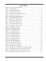
List of Figures ...................................................................................................................vi
List of Tables .....................................................................................................................ix
Section 1: General Information
About the Atlas Monitor........................................................................................................ 1
Help Information ................................................................................................................... 2
Agency Approvals ................................................................................................................. 3
Warning, Cautions and Notes................................................................................................ 3
Product Model Number Structure......................................................................................... 5
623xP Main Menu Architecture............................................................................................ 6
622xP Main Menu Architecture............................................................................................ 7
621xP Main Menu Architecture............................................................................................ 8
Atlas System Block Diagram ................................................................................................. 9
Section 2: Service
Incoming Inspection ............................................................................................................ 11
Calibration and Maintenance Schedule.............................................................................. 12
Setting Date and Time ......................................................................................................... 14
Pangea Communication Protocol ........................................................................................ 14
BP Calibration ...................................................................................................................... 14
50mmHg Calibration............................................................................................................ 17
250mmHg Calibration.......................................................................................................... 17
CO2 Reset (623xx Models Only).......................................................................................... 18
ET CO2 Calibration .............................................................................................................. 19
No-Load Battery Voltage Calibration .................................................................................. 20
Battery Voltage Calibration.................................................................................................. 21
Printer Print Adjustment ..................................................................................................... 22
Temperature Calibration...................................................................................................... 23
Calibration Date Set ............................................................................................................. 24
Explanation of an Atlas Service Screen.............................................................................. 25
Software Upgrade Procedure............................................................................................... 27
Down Loading NVRAM Files.............................................................................................. 28
ii
Welch Allyn Atlas Monitor
Service Manual 6200-43E Rev. D
Section 3: Functional tests and Trouble Shooting
Power on Self Test ...............................................................................................................37
Menu Functional Test..........................................................................................................38
BP Test..................................................................................................................................40
Static Manometer Accuracy Test.........................................................................................41
BP Leak Test ........................................................................................................................42
Over 15 mmHg Test .............................................................................................................42
BP Dump Verification Test ..................................................................................................43
Hardware Fail Safe Tests .....................................................................................................43
ECG/Respiration Test...........................................................................................................44
SpO2 Test..............................................................................................................................45
Temperature Test .................................................................................................................45
CO2 Functional Test.............................................................................................................45
Battery Functional Test........................................................................................................46
Printer Functional Test ........................................................................................................47
Print on Alarm Test..............................................................................................................47
Software/Firmware ..............................................................................................................47
ECG Alarms Test ..................................................................................................................48
Respiration Alarms Test ......................................................................................................50
SpO2 Alarm Test ..................................................................................................................51
Silence Alarm Test...............................................................................................................52
CO2/RESP Test .....................................................................................................................52
Blood Pressure Alarm Test ..................................................................................................53
Trouble Shooting..................................................................................................................56
Section 4: Disassembly and Repair
About Section 4 ...................................................................................................................63
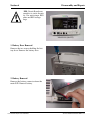
Battery Door Removal..........................................................................................................64
Battery Removal...................................................................................................................64
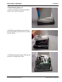
Rear Housing Removal ........................................................................................................65
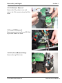
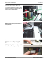
Printer Cable and Display Cable Removal ..........................................................................66
Power Supply Ground Wire Removal.................................................................................66
Tie Wrap Removal................................................................................................................67
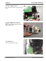
CPU Removal .......................................................................................................................67
Service Manual 6200-43E Rev. D
Welch Allyn Atlas Monitor iii
Main PCB Removal .............................................................................................................. 67
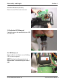
Main PCB Side Connector Removal.................................................................................... 68
Main PCB Hose and Wire Removal..................................................................................... 68
Pump Removal..................................................................................................................... 68
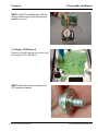
CO2 Exhaust Removal.......................................................................................................... 69
Pryon PCB Removal............................................................................................................. 69
E-Pac Foam Removal (Top). ................................................................................................ 69
Power Supply Removal. ...................................................................................................... 70
Power Supply Fuse Location .............................................................................................. 70
Fan Removal ........................................................................................................................ 70
E-Pac Removal (Lower)........................................................................................................ 71
Deflection PCB Removal...................................................................................................... 71
CRT Removal ....................................................................................................................... 71
Display PCB Removal .......................................................................................................... 72
Printer Door Button Removal .............................................................................................. 73
Printer Assembly Locking Tab Release. .............................................................................. 73
Printer Positioning Slot Removal........................................................................................ 74
Printer Assembly Removal. ................................................................................................. 74
Printer Lip Assembly. .......................................................................................................... 74
Printer Cable Routing. ......................................................................................................... 75
Appendix A: Theory of Operation
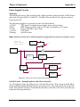
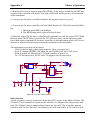
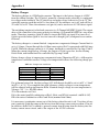
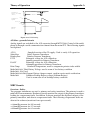
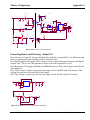
Power Supply Circuits......................................................................................................... 77
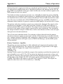
Model 622 and Model 623................................................................................................... 80
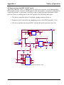
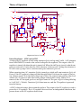
On/Off Circuits .................................................................................................................... 81
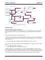
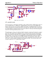
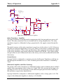
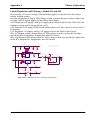
Battery Charger .................................................................................................................... 84
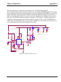
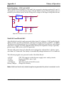
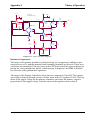
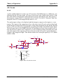
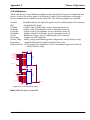
NIBP Circuits ...................................................................................................................... 87
CRT Deflection Board .......................................................................................................... 92
Vertical Amplifier: ............................................................................................................... 92
Recorder Electronics............................................................................................................ 96
Power Supply – 24 Switcher............................................................................................... 96
Motor Driver:........................................................................................................................ 97
Patient Isolated Circuits ...................................................................................................... 98
Linear Regulators and Filtering – Model 621 ..................................................................... 99
iv
Welch Allyn Atlas Monitor
Service Manual 6200-43E Rev. D
Linear Regulators and Filtering – Model 622 and 623 .....................................................100
A/D Circuits .......................................................................................................................101
A/D Multiplexer.................................................................................................................102
Serial Communication.......................................................................................................103
Signal Isolation ..................................................................................................................104
ECG Circuits.......................................................................................................................104
Impedance Respiration (Model 622/623 only) .................................................................109
SpO2 Circuits .....................................................................................................................110
Appendix B: Repair Parts Lists
621N0 .................................................................................................................................113
621NP .................................................................................................................................116
621S0..................................................................................................................................119
621SP..................................................................................................................................121
622N0 .................................................................................................................................124
622NP .................................................................................................................................127
622S0..................................................................................................................................130
622SP..................................................................................................................................133
623NP .................................................................................................................................136
623SP..................................................................................................................................142
Appendix C: Interconnect Diagram
Interconnect diagram 620396 Rev A.................................................................................145
Appendix D: Atlas Drawings and Electrical Schematics
See List of Figures on page v for individual drawings.....................................................146
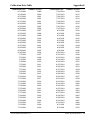
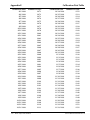
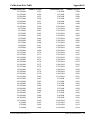
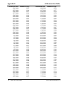
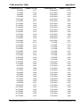
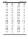
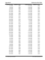
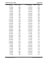
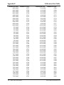
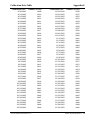
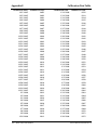
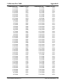
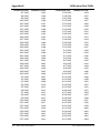
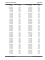
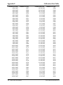
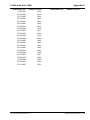
Appendix E: Calibration Date Table
Calibration Date Index Table. ............................................................................................187
Appendix F: Serial Number Cut in History. ...............................................211
Appendix G: Atlas Calibration and Functional Test Form........................213
Service Manual 6200-43E Rev. D
Welch Allyn Atlas Monitor v
List of Figures
Figure 1-1. 623xP Main Menu Architecture. ........................................................................ 6
Figure 1-2. 622xP Main Menu Architecture. ........................................................................ 7
Figure 1-3. 621xP Main Menu Architecture. ........................................................................ 8
Figure 1-4. Atlas System Block Diagram .............................................................................. 9
Figure 2-1. Example of a new HyperTerminal connection. ............................................... 15
Figure 2-2. Choosing COM1 in HyperTerminal.................................................................. 15
Figure 2-3. HyperTerminal Port Settings. ........................................................................... 16
Figure 2-4. Photo of Atlas BP calibration setup. ................................................................ 17
Figure 2-5. Example of CO2 calibration setup. ................................................................... 21
Figure 2-6. Example and Explanation of an Atlas Service Screen .................................... 25
Figure 2-7. Pangea prompt in HyperTerminal .................................................................... 29
Figure 2-8. Choosing “Send Text File” in HyperTerminal................................................. 29
Figure 2-9. Choosing directory where NVRAM files are stored. ....................................... 30
Figure 2-10. Choosing the nvram_cal_init.txt file. ............................................................. 30
Figure 2-11. Pangea screen after opening the nvram_cal_init.txt file. .............................. 31
Figure 2-12. Pangea screen after opening the nvram_common.txt file. ............................ 31
Figure 2-13. Pangea prompt after opening the model# file................................................ 32
Figure 2-14. Pangea screen after loading a language file. .................................................. 33
Figure 2-15. Pangea screen after downloading the nvram_printer.txt file. ....................... 34
Figure 2-16. Pangea screen nvram set serial command. .................................................... 35
Figure A-1. Model 621 DC/DC circuit block diagram. ....................................................... 77
Figure A-2. On/Off Control Circuits. .................................................................................. 78
Figure A-3. Model 621 Buck converter. .............................................................................. 79
Figure A-4. Model 621 linear regulation. ........................................................................... 80
Figure A-5. DC/DC circuit diagram..................................................................................... 81
Figure A-6. Boost converter and off/on switch. ................................................................. 82
Figure A-7. Boost converter................................................................................................. 83
Figure A-8. Battery charging. .............................................................................................. 85
Figure A-9. Linear regulator. ............................................................................................... 86
Figure A-10. NIBP PWM A/D converter. ............................................................................ 86
Figure A-11. PWM timing. .................................................................................................. 87
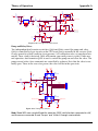
Figure A-12. Primary transducer amplifier......................................................................... 89
Figure A-13. Safety transducer amplifier............................................................................ 90
vi
Welch Allyn Atlas Monitor
Service Manual 6200-43E Rev. D
Figure A-14. Over pressure fault circuit. ............................................................................91
Figure A-15. Pump relay circuit..........................................................................................91
Figure A-16. Ramp generator circuit...................................................................................92
Figure A-17. Vertical amplifier circuit................................................................................93
Figure A-18. Horizontal amplifier grid voltage circuit. .....................................................95
Figure A-19. Video amplifier circuit. ..................................................................................96
Figure A-20. Recorder power supply circuit. .....................................................................97
Figure A-22. Print head temperature circuit. .....................................................................98
Figure A-23. Patient isolation circuit..................................................................................99
Figure A-24. Model 621 line regulation and filtering. .......................................................99
Figure A-25. Model 622/623 line regulation and filtering. ..............................................100
Figure A-26. A/D converter circuit. ..................................................................................101
Figure A-27. A/D multiplexer circuit. ..............................................................................102
Figure A-28. Serial communication circuit. .....................................................................104
Figure A-29. Defib protect and RFI filtering circuit. ........................................................105
Figure A-30. Input buffer circuit.......................................................................................105
Figure A-31. Lead select circuit. .......................................................................................106
Figure A-32. Differential amp/slew rate amp circuit. ......................................................107
Figure A-33. Right leg drive circuit. .................................................................................107
Figure A-34. High pass and gain stage circuit. .................................................................108
Figure A-35. Temperature amplifier circuit......................................................................108
Figure A-36. Respiration drive circuit. .............................................................................109
Figure A-37. Respiration diff amp circuit.........................................................................110
Figure A-38. Gain and filter circuit...................................................................................110
Figure C-1. Atlas Interconnect Diagram............................................................................145
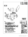
Figure D-1. Atlas model 200 main board..........................................................................147
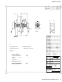
Figure D-2. Atlas model 200 NIBP electronics. ................................................................148
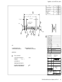
Figure D-3. Atlas model 200 power supply......................................................................149
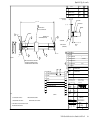
Figure D-4. Atlas Power isolation /SpO2 interface...........................................................150
Figure D-5. Atlas model 200 ECG amp. ............................................................................151
Figure D-6. Atlas ECG A/D interface.................................................................................152
Figure D-7. Atlas CPU subsystem. ....................................................................................153
Figure D-8. Atlas FPGA. ....................................................................................................154
Figure D-9. Atlas 200/210/220 I/O filters. ........................................................................155
Service Manual 6200-43E Rev. D
Welch Allyn Atlas Monitor vii
Figure D-10. Flash, SDRAM HRESET config word. ......................................................... 156
Figure D-11. Power PC MP C823 CPU. ............................................................................. 157
Figure D-12. Power distribution........................................................................................ 158
Figure D-13. Front panel display. ..................................................................................... 159
Figure D-14. Key board scanner. ....................................................................................... 160
Figure D-15. Temp/pulse LED drivers. ............................................................................. 161
Figure D-16. NIBP LED drivers. ........................................................................................ 162
Figure D-17. SpO2 LED drivers. ........................................................................................ 163
Figure D-18. CRT deflection board. .................................................................................. 164
Figure D-19. Printer electronics. ....................................................................................... 165
Figure D-20. Model 220 main board. ................................................................................ 166
Figure D-21. 210/220 NIBP electronics............................................................................. 167
Figure D-22. DC/DC power supply.................................................................................... 168
Figure D-23. Power isolation/SpO2 interface. .................................................................. 169
Figure D-24. 210/220 ECG amp......................................................................................... 170
Figure D-25. 210/220 ECG A/D interface.......................................................................... 171
Figure D-26. 210/220 Respiration circuit. ........................................................................ 172
Figure D-27. 210/220 serial communication. ................................................................... 173
Figure D-28. 200/210/220 transformer isolation. ............................................................. 174
Figure D-29. 200/210/220 ECG patient cable. .................................................................. 175
Figure D-30. 200/210/220 power supply sub assy. .......................................................... 176
Figure D-31. 220 ETCO2 PCB assembly. ........................................................................... 177
Figure D-32. 200/210/220 Power supply. ......................................................................... 178
Figure D-33. Nonin SpO2 Board........................................................................................ 179
Figure D-34. Motor Stepper. .............................................................................................. 180
Figure D-35. Pump Pneumatic. ......................................................................................... 181
Figure D-36. 200/210/220 ECG cable assembly. ............................................................... 182
Figure D-37. CO2 cable assembly. ..................................................................................... 183
Figure D-38. Nellcor sensor cable assy. ............................................................................ 184
Figure D-39. 200/210/220 Pneumatic sub assy................................................................. 185
Figure D-40. 220 CO2 cable assy. ...................................................................................... 186
viii
Welch Allyn Atlas Monitor
Service Manual 6200-43E Rev. D
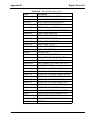
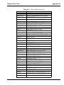
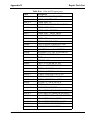
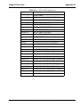
List of Tables
Table 1-1. Operator manual part numbers. ...........................................................................1
Table 2-1. Atlas Packing List. ..............................................................................................11
Table 2-2. Tools Required for Service. ................................................................................13
Table 2-3. Software Revision Table .....................................................................................26
Table 2-4. Files needed to download language(s)...............................................................33
Table 3-1. Transducer pressure table...................................................................................41
Table 3-2 Resistor and temperature reference. ...................................................................45
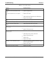
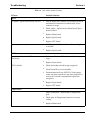
Table 3-3. Atlas failure trouble shooting.............................................................................56
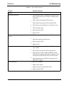
Table 3-4. Atlas failure trouble shooting.............................................................................57
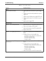
Table 3-5. Atlas failure trouble shooting.............................................................................58
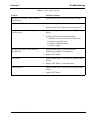
Table 3-6. Atlas failure trouble shooting.............................................................................59
Table 3-7. Atlas failure trouble shooting.............................................................................60
Table 3-8. Atlas failure trouble shooting.............................................................................61
Table A-1. Temperature coefficient. ....................................................................................84
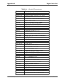
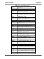
Table B-1. Atlas 621N0 repair parts ..................................................................................113
Table B-2. Atlas 621NP repair parts. .................................................................................116
Table B-3. Atlas 621S0 repair parts...................................................................................119
Table B-4. Atlas 621SP repair parts...................................................................................121
Table B-5. Atlas 622N0 repair parts. .................................................................................124
Table B-6. Atlas 622NP repair parts. .................................................................................127
Table B-7. Atlas 622S0 repair parts...................................................................................130
Table B-8. Atlas 622SP repair parts...................................................................................133
Table B-9. Atlas 622NP repair parts. .................................................................................136
Table B-10. Atlas 623SP repair parts.................................................................................139
Table B-11. Atlas 623NP repair parts. ...............................................................................142
Table D-1. Atlas drawings revision page...........................................................................146
Table F-1. Changed to a new BP Valve..............................................................................211
Table F-2. Changed E-Pac and Changed to class B power supply. ..................................211
Table F-3. Upgraded printer cable to a cable with foam tape. .........................................211
Table F-4. Upgraded Revision level of CPU from 501 to 502...........................................211
Table F-5. Upgraded Revision level of Nellcor SpO2 to 506............................................212
Service Manual 6200-43E Rev. D
Welch Allyn Atlas Monitor ix
x
Welch Allyn Atlas Monitor
Service Manual 6200-43E Rev. D
General Information
Section 1
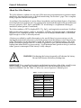
About the Atlas Monitor
The Atlas Monitor combines in one unit all the necessary measurements for patients under
anesthesia, for surgical recovery, or bed side monitoring. See Section 1, page 5 for a complete
listing of product models and options.
According to the standards of care for Nurse Anesthetists and Anesthesiologists, all patients
receiving conscious sedation are to be continuously monitored throughout the procedure and
recovery phase by ECG, SpO2, and NIBP. CO2 monitoring is a requirement during gas
anesthesia (when patient is ventilated).
The Atlas combines a CRT to display ECG, CO2, SpO2, and respiration waveforms. It utilizes
LEDs for the other numeric values to maximize visibility and viewing angle. Although not
designed to be a transport product, the monitor has an integral handle and it is small and
light enough at 13 lbs. to be easily moved.
A battery was added to enable the monitor to be used if there is a power outage or to be
unplugged momentarily when moved with the patient from the surgery room to the recovery
room. The battery was not designed to make the Atlas into a transport monitor. The Atlas
monitor should be plugged into AC as much as possible to give you the maximum battery
backup time when there is a power outage. It will maintain unit operation for up to an hour
when power is interrupted if the battery is fully charged.
WARNING: Discharging the battery frequently will shorten the battery
life and will shorten the battery backup time.
IMPORTANT: For a complete description on the function and use of the Atlas, as well as user
safety warnings, cautions, and warranty information, read and understand the Atlas
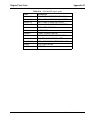
Operator’s Manual. See the Table 1-1 below for correct Operator’s Manual part #.
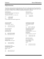
Table 1-1. Operator manual part numbers.
Service Manual 6200-43E Rev. D
Language
English
French
German
Italian
Part#
6200-42E
6200-42F
6200-42G
6200-42I
Spanish
Portuguese
Japanese
Chinese
6200-42S
6200-42P
6200-42J
6200-42C
Welch Allyn Atlas Monitor 1
Section 1
General Information
Help Information
To assure correct operation and performance all service and repairs must be performed by
fully trained and properly equipped personnel, using genuine replacement parts and correct
procedures. Failure to do so will also invalidate the product warranty.
Welch Allyn Inc.
State Street Plant /Corporate Headquarters
4341 State Street Road
Skaneateles Falls, NY 13153-0220, USA
tel:
1-800-535-6663
315-685-4100
fax:
315-685-3361
www.welchallyn.com/medical/support/tech
Welch Allyn GMBH
Zollerstrasse 2-4
72417 Jungingen, Germany
tel:
fax:
(011) 49-7477-927186
(011) 49-7477-927193
Welch Allyn UK Ltd
St. Georges House
Vernon Gate, Derby
England DE1 1UQ
tel:
fax:
mob:
(011) 44-01332-206208
(011) 44-01332-206209
(011) 44-0467-301814
Welch Allyn Singapore Ltd
300 Beach Road, #25-08
The Concourse
Singapore 199589, Singapore
tel:
fax:
(011) 65-291-0882
(011) 65-291-5780
MD International
11300 N.W. 41st Street
Miami, FL 33178 USA
tel:
fax:
305-669-9003
305-669-1971
Welch Allyn France SARL
814 rue Charles de Gaulle
77100 Mareuil les Meaux
France
tel:
Fax:
( 011) 33 1.6009.3366
(011) 33 1 .6009.6797
Welch Allyn Australia Pty
The Metro Centre Unit 5
38-46 South Street
Rydalmere NSW 2116, Australia
Postal address:
PO Box 132
Rydalmere NSW 1701, Australia
tel:
fax:
(011) 612 9638-3000
(011) 612 9638-3500
China Service Center
Room 708 Central Plaza
No. 277 Huang Pi Bei Rd.
Huang Pi District
Shanghai 200003
China
tel:
fax:
(011) 86-21-63279631
(011) 86-21-63279632
Welch Allyn Japan K.K.
Bon Marusan 8F, 3-5-1 Kanda
Jinbo-Cho, Chiyoda-Ku
Tokyo 101-0051
Japan
tel:
fax:
2
(011) 813-5212-7391
(011) 813-3261-7372
Welch Allyn Atlas Monitor
Service Manual 6200-43E Rev. D
General Information
Section 1
Agency Approvals
C
LI
STED
74227
US
ETL Listed
U L 2 6 01- 1 ,
C S A C 2 2 . 2 N o . 6 01. 1
I E C 6 0 6 01- 1 , A S 3 2 0 0 . 1
I E C 6 0 6 01- 1- 2
The CE mark on this product indicates that it
has been tested to and conforms with the
provisions noted
within the 89/336/ECC
Electromagnetic Compatibility Directive.
Australia EMC Framework Compliance
N344
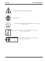
Warning, Cautions and Notes
All operating and service personnel should be familiar with the general safety information
in this summary. Specific warnings and cautions will also be found throughout the operators manual. Such specific warnings and cautions may not appear here in the summary.
Electrical Shock Hazard
CAUTION
Service Manual 6200-43E Rev. D
Welch Allyn Atlas Monitor 3
Section 1
General Information
ATTENTION. Consult accompanying document
Handle With Care
95%
MAX
Storage Humidity. Refer to technical specifications in operator's
for more details.
Storage temperature. Refer to technical specifications in operator's
manual for more details.
Lead Acid Battery. For disposal see maintenance
section in opertor's manual
PB
4
Welch Allyn Atlas Monitor
Service Manual 6200-43E Rev. D
General Information
Section 1
Product Model Number Structure
621S0-E1 ECG, Nonin SpO2, NIBP
621SP-E1 ECG, Nonin SpO2, NIBP, Printer
621N0-E1 ECG,Nellcor SpO2,NIBP
621NP-E1 ECG,Nellcor SpO2,NIBP, Printer
622S0-E1 ECG, Nonin SpO2, NIBP, Temp, Respiration, Battery, RS232
622SP-E1 ECG, Nonin SpO2, NIBP, Temp, Respiration, Battery, RS232, Printer
622N0-E1 ECG, Nellcor SpO2, NIBP, Temp, Respiration, Battery, RS232
622NP-E1 ECG, Nellcor SpO2, NIBP, Temp, Respiration, Battery, RS232, Printer
623SP-E1 ECG, Nonin SpO2, NIBP, ETCO2, Temp, Respiration, Battery, RS232, Printer
623NP-E1 ECG, Nellcor SpO2, NIBP, ETCO2, Temp, Respiration, Battery, RS232, Printer
Product Structure Meaning:
The first three digits in the product structure sequence designates the model number. The
fourth character in the sequence designates the SpO2. The fifth character in the sequence
designates if it has a printer or not. The first suffix designates the country language when
shipped. The second suffix designates the power cord shipped with the Atlas.
First Three Characters: Model number, 621, 622, 623
Fourth Character: N=Nellcor SpO2, S=Nonin SpO2
Fifth Character: P=Printer, 0=No Printer
First Suffix: E = English, F= French, G= German, I= Italian, S= Spanish, P= Portuguese C =
Chinese,
J= Japanese
Second Suffix:
1 = US, Canada, Japan
2 = European
4 = United Kingdom
6 = Australian
Service Manual 6200-43E Rev. D
Welch Allyn Atlas Monitor 5
Section 1
General Information
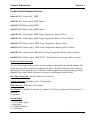
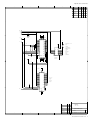
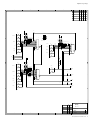
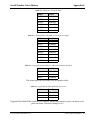
623xP Main Menu Architecture
Figure 1-1. 623xP Main Menu Architecture.
623xP
Waveform
screen
Date/Time
Screen
Trend
Screen
Set date & time
Advanced
Configuration
Date/Time
Screen
Co2
Reset
Advanced Configuration Screen
Language
Silence duration
ECG gain
ECG lead set
ECG speed
ECG bandwidth
Initial pressure
MAP
Second trace selection
Temperature units
Respiration speed
CO 2 units
Print on alarm (only with software Rev.
BB.2.2000 or higher)
Service Mode Screen
Save
Settings
Service Mode
Screen
Verify manometer
Reset to factory defaults
Battery test
Calibrate Co 2
CRT test pattern
Printer test pattern (Models 621SP and
621NP only)
LED test
Button test
Display A/D channels *
NOTE: The Print on alarm function in Advanced configuration mode screen is only
available with software version BB.2.2000 and higher.
*
6
NOTE: The Display A/D channels function in the Service Mode Screen only allows
you to view system information by pressing the SET button. It does not allow
you to change system settings.
Welch Allyn Atlas Monitor
Service Manual 6200-43E Rev. D
General Information
Section 1
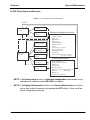
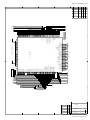
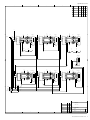
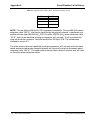
622xP Main Menu Architecture
Figure 1-2. 622xP Main Menu Architecture.
622xP
Waveform
screen
Date/Time
Screen
Trend
Screen
Set date & time
Advanced
Configuration
Date/Time
Screen
Advanced Configuration Screen
Language
Silence duration
ECG gain
ECG lead set
ECG speed
ECG bandwidth
Initial pressure
MAP
Second trace selection
Temperature units
Respiration speed
Print on Alarm (Only with software Rev.
BB.2.2000 and higher.)
Service Mode Screen
Save
Settings
Service Mode
Screen
Verify manometer
Reset to factory defaults
Battery test
CRT test pattern
Printer test pattern (Models 622SP and
622NP only)
LED test
Button test
Display A/D channels *
NOTE: The Print on alarm function in Advanced Configuration Screen is only
available with software version BB.2.2000 and higher.
NOTE: On models 622S0 and 622N0 delete the Print test pattern function in the
Service Mode Screen. Model 622S0 and 622N0 do not come with printers.
*
NOTE: The Display A/D channels function in the Service Mode Screen only allows
you to view system information by pressing the SET button. It does not allow
you to change system settings.
Service Manual 6200-43E Rev. D
Welch Allyn Atlas Monitor 7
Section 1
General Information
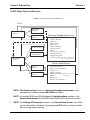
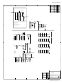
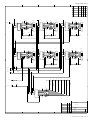
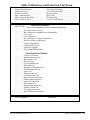
621xP Main Menu Architecture
Figure 1-3. 621xP Main Menu Architecture.
621xP
Waveform
screen
Date/Time
Screen
Trend
Screen
Set date & time
Advanced
Configuration
Advanced Configuration Screen
Language
Silence duration
ECG gain
ECG lead set
ECG speed
ECG bandwidth
Initial pressure
MAP
Second trace selection
Print on Alarm (Only with software Rev.
BB.2.2000 and higher.)
Date/Time
Screen
Service Mode Screen
Save
Settings
Service Mode
Screen
Verify manometer
Reset to factory defaults
CRT test pattern
Printer test pattern (Models 621SP and
621NP only)
LED test
Button test
Display A/D channels
*
NOTE: The Print on alarm function in Advanced configuration mode screen is only
available with software version BB.2.2000 and higher.
NOTE: On models 621S0 and 621N0 delete the Print test pattern function in the
Service Mode Screen. Model 622S0 and 622N0 do not come with printers.
*
8
NOTE: The Display A/D channels function in the Service Mode Screen only allows
you to view system information by pressing the SET button. It does not allow
you to change system settings.
Welch Allyn Atlas Monitor
Service Manual 6200-43E Rev. D
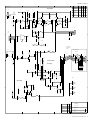
Service Manual 6200-43E Rev. D
Rs-232
Test
Port
RS-232
Drivers
(Isolated)
TTL
RS-232
UART-1
Bus Config.
Register
UART-2
Motorola CPU
MPC823Z3
SPO2
Sensor
SPO2
Sub-System
(Isolated)
TTL
RS-232
512 X 16 Flash
4M X 16
SDRAM
Pump
Valve
NIBP
Pnuematic
Control
Drivers
2
GPIO
AC
Line
Battery
Power
Supply
ON,OFF
ACON,
SYNC
GPIO
Local System Bus
Address,Data,Control
5 Volt Video Signals:
H-Sync, V Sync, Video
Primary
Sensor
NIBP
Front End
PW
Timer 2
GPIO
SPI
P
W
Configuration
EEPROM
Temp
EKG
X5
Front End
EKG +
Temp
(Isolated)
Print Head
Clock, Load
Strobe
24
Keys
15 X 7
31 LEDs
Key
LED
Board Drivers
Front Panel
3-wire SPI + nine
chip select
Printer
Subsystem
AT90A4414
8 bit
Controller
Motor
CO2 Sensor
Driver Motor
CO2 SubSystem
CRT SubSystem
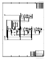
General Information
Section 1
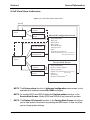
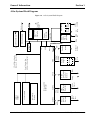
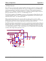
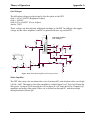
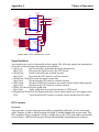
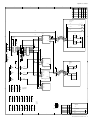
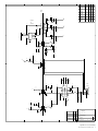
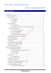
Atlas System Block Diagram
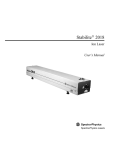
Figure 1-4. Atlas System Block Diagram
Welch Allyn Atlas Monitor 9
Service
Section 2
Incoming Inspection
NOTE: Use the following guidelines when unpacking the monitor from its shipping carton.
1. Before opening the monitor shipping carton, check for damage.
2. If damage is apparent, stop unpacking the carton and contract the shipping company for
further instructions. If the carton is intact, unpack the monitor.
3. With the monitor out of its carton, check to see that all the items listed on the packing
slip are in the shipping carton. See table 2-1 below.
Table 2-1. Atlas Packing List.
Qty.
1
1
1
1
1
3
1
1
1
1
1
1
1
1
1
Description
Warranty card
Adult Durable 1pc. Cuff
Large Adult Durable 1pc. Cuff
5ft. Straight Hose
ECG Patient Cable (Three Lead)
ECG Lead Wires
SpO 2 Sensor/ Finger Clip
ETCO 2 Water Trap
ETCO 2 Scrubber
Nasal Canula
Atlas Monitor
Detachable Power Cord
Printer Paper Roll
Operation Manual
Skin Temperature Probe
623 only
623 only
623 only
622/623 only
4. If an item is missing, first check the carton, then check with your receiving department. If necessary
contact Welch Allyn at the address and phone number shown on Section 1.
5. Clean and disinfect by following the instructions printed in the Operator Manual.
NOTE: Perform all functional tests as listed in Section 3 before and after servicing.
Operate the Atlas to verify the customer complaint before making any changes to the unit.
Call the customer if the complaint is unclear.
If the unit has caused or is suspected of having caused an injury of any type: DO NOT
DISASSEMBLE OR REPAIR THE UNIT IN ANY WAY. Contact Welch Allyn Customer
Service immediately.
Service Manual 6200-43E Rev. D
Welch Allyn Atlas Monitor 11
Section 2
Service
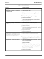
Calibration and Maintenance Schedule
The Atlas Monitor must be serviced by authorized Welch Allyn personnel or agents at 6
month intervals. Maintenance requirements are specified for 6 month and 12 month service
intervals. The monthly CO2 Reset operation can be performed by the user.
Service Interval
Maintenance Requirements
Every 6 months:
CO2 Calibration
Every 12 months:
BP calibration, CO2 reset, battery voltage calibration,
printer adjustment,and temperature calibration.
Complete functional test
12 Welch Allyn Atlas Monitor
Service Manual 6200-43E Rev. D
Service
Section 2
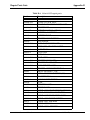
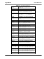
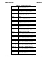
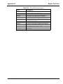
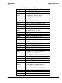
Table 2-2. Tools Required for Service.
Description
100cc Test Volume
500cc Test Volume
T-10 TORX screwdriver
7/16" deep socket for Temperature Port nut
Squeeze Bulb and Valve
Calibrated Manometer (0-10PSIG)
Bio-Tek (NIBP TESTER)
Pneumatic Tubing
Pneumatic Tubing (coiled)
"Y" Fitting "Optional"
"T" Fitting (3)
Nonin Patient Simulator
Nonin Cable
Calibrated Thermometer for 90F to 115F range
LG, Adult Cuff/Bag
Nellcor Patient Simulator For atlas with "MP
204/205 SpO2 PCB ONLY "
Nellcor Patient Simulator "MP 506 PCB ONLY "
Nellcor Sensor Cable "Purple Connectors" will work
on all Atlas units with 204/205/506 SpO2 PCB
Nellcor Sensor Cable "Gray Connectors" "For Atlas
units with MP 204/205 SpO2 PCB only"
ECG Simulator with Impedance Respiration
ECG Patient Cable (5 lead AHA)
ECG Patient Cable (5 lead IEC)
ECG leads, 5 Lead (IEC)
ECG leads, 5 Lead AHA
Certified Gas "10% CO2,10% O2, balance N2"
ETCO2 Water Trap (package of 5)
ETCO2 Scrubber
ETCO2 Adult Nasal Sample Line
Surface Sensor, Temperature
Atlas Repair and Calibration Software
Printer Paper - Case
Digital Multimeter with 10mV accuracy on a 10V
scale; 10A Range
Adjustable DC power supply 5A @ 7V
Battery cable assembly
Atlas interface cable to PC
PC with Windows 95 and above and with
HyperTerminal serial port software
1/4" Mono Phono Jack
1000 Ohm precision resistor 1%
1200 Ohm precision resistor 1%
1350 Ohm precision resistor 1%
1540 Ohm precision resistor 1%
1870 Ohm precision resistor 1%
Service Manual 6200-43E Rev. D
Part#
T-112189
T-112854
XTD-10
5088-01
Digimano 1000
BP Pump
5200-19
5200-19M
9586TPK4
9858TPK4
8000S
5200-52
1002-3FC
5200-02
Company
Welch Allyn
Welch Allyn
Xcelite brand
Generic 1/4" drive
Welch Allyn
Netech
Bio-Tek
Welch Allyn
Welch Allyn
Welch Allyn
Welch Allyn
Nonin
Nonin
ERTCO
Welch Allyn
SRC-2
Nellcor
SRC-MAX
Nellcor
DEC-8
Nellcor
EC-8
214B
6200-02
6200-04
6200-08
6200-06
0304724SRBD
6200-20
6200-21
6200-22
6200-15
620538
Nellcor
DNI Nevada
Welch Allyn
Welch Allyn
Welch Allyn
Welch Allyn
Scott Medical Products
Welch Allyn
Welch Allyn
Welch Allyn
Welch Allyn
Welch Allyn
6200-40
Welch Allyn
620174-1
6200-60
Welch Allyn
Welch Allyn
Part of Windows 95 &
above
Welch Allyn Atlas Monitor 13
Section 2
Service
Setting Date and Time
NOTE: Check date and time before doing any calibration. Set date and time if incorrect. Set
time and date as follows;
1. Turn Atlas on.
2. Press CLOCK button next to power on button to check date and time. Use the far right
SELECT button to scroll. Highlight the date or time that needs changed.
3. Press the SET button to adjust date and time.
4. Press CLOCK button to exit.
Pangea Communication Protocol
The Pangea Communication Protocol allows interaction of the Atlas with the computer
through the serial interface port. A prompt is emitted at the computer screen when the
instrument powers up and is ready to accept commands. The prompt is Pangea>. A prompt
is emitted after the completion of each pangea command. Pangea commands are case sensitive. They are in English only.
BP Calibration
Required material.
1. 500cc vessel
2. Squeeze bulb with one-way valve
3. PC with HyperTerminal
4. Calibrated digital manometer
5. Tubing and T fittings
6. Serial cable
NOTE: To start HyperTerminal you must have Windows7 95 or higher installed on your
computer.
1. From the Windows main screen follow the following sequence:
Start !Programs ! Accessories ! Communication ! HyperTerminal
2. HyperTerminal setting are:
9600 baud rate, 8 bit word, 1 stop bit
no parity, no flow control
ANSI character set
14 Welch Allyn Atlas Monitor
Service Manual 6200-43E Rev. D
Service
Section 2
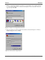
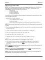
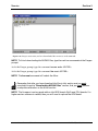
3. When you open HyperTerminal you will see a screen similar to the example in Figure
2-1. You will be prompted for a connection description. Choose any name. After you
type in a name click OK.
Figure 2-1. Example of a new HyperTerminal connection.
4. The next window you will see will be the window as shown in Figure 2-2. Click on
Connect using then click on COM1.
Figure 2-2. Choosing COM1 in HyperTerminal.
Service Manual 6200-43E Rev. D
Welch Allyn Atlas Monitor 15
Section 2
Service
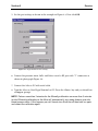
5. Set the port settings as shown in the example in Figure 2-3. Now click OK.
Figure 2-3. HyperTerminal Port Settings.
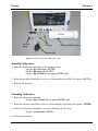
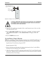
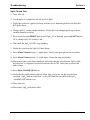
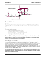
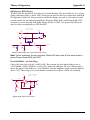
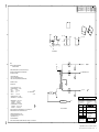
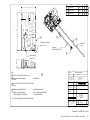
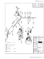
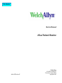
6. Connect the pressure meter, bulb, and 500cc vessel to BP port with “T” connectors as
shown in photograph Figure 2-4.
7. Connect the Atlas to PC with serial cable.
8. Turn the Atlas on. Start HyperTerminal on PC. Press the <Enter> key and you should see
a Pangea> prompt.
NOTE: Take no more than 3 minutes for the 50mmHg calibration nor more than 3 minutes
for the 250mmHg calibration as the Atlas will automatically, as a safety feature, open the
blood pressure valve. If this happens you will have to turn the Atlas off then back on again
and restart the calibration again.
16 Welch Allyn Atlas Monitor
Service Manual 6200-43E Rev. D
Service
Section 2
T112854
Pressure
Meter
T Fittings
Calibrated 500cc Volume
Squeeze Bulb
Figure 2-4. Photo of Atlas BP calibration setup.
50mmHg Calibration
1. Enter the following commands at the Pangea prompt.
Pangea> bp valve close <ENTER>
Pangea> bp safety off <ENTER>
Pangea> bp cal 5000 Do not press <ENTER> yet!
2. Raise the pressure with bulb to as close to 50.00mmHg as possible. Now press <ENTER>.
3. Release the pressure.
250mmHg Calibration
1. Enter the following command
Pangea> bp cal 25000 Do not press <ENTER> yet!
2. Raise the pressure with bulb as close to 250.00 mmHg as possible. Now press < ENTER >
3. Enter the following command to save the calibration in the Atlas.
Pangea> nvram write <ENTER>
4. Release the pressure.
Service Manual 6200-43E Rev. D
Welch Allyn Atlas Monitor 17
Section 2
Service
CO2 Reset (623xx Models Only)
Required material. 1. Watertrap
2. Scrubber
NOTE: The Scrubber looks similar to a watertrap, but it is filled with white granules. The
scrubber is included with the 623XX models only.
NOTE: Make sure date and time are correct before performing the CO2 reset.
1. Turn Atlas on. Make sure the watertrap and scrubber are NOT attached to the Atlas.
2. Press the DATE/TIME button on the lower right of the monitor. The Set Date and Time
and Other Options menu will be displayed.
3. Press the CO2/RESP ALARMS Off button. The CO2 Reset screen will appear.
4. You will see the following messages on the CRT.
“CO2 Reset”
“Install CO2 scrubber”
“Press Trend to abort”
5. Install the watertrap to the Atlas. Install the scrubber to the watertrap.
6. You will see the following instructions on the screen.
“Warming up” will be flashing on CRT.
“May take up to five minutes” on CRT.
“Press Trend to abort” on CRT.
7. After about 5 minutes you will see on the CRT.
“CO2 Reset”
“Reset complete”
“Remove CO2 scrubber”
“Press the trend button to exit”
8. Remove the CO2 watertrap and scrubber.
9. Press TREND button to return to idle screen.
Replace watertrap after every six hours of use. Treat watertrap and used CO2
sample lines as bio hazard material!
18 Welch Allyn Atlas Monitor
Service Manual 6200-43E Rev. D
Service
Section 2
ET CO2 Calibration
Required material:
1. Tank of approximately 10% CO2, balance N2 (certified) Blood Gas Mixture.
2. Tubing and T connectors.
3. Watertrap and scrubber.
1. Make sure the watertrap and scrubber are not attached to the Atlas. Turn the Atlas on.
2. Place the instrument into the Service Mode by pressing the DATE/TIME button. Make
sure date and time are correct. Press the LEAD SELECT button.
3. Press SELECT button and scroll down to Calibrate CO2.
The message “Install CO2 Scrubber” will appear on the right side of screen.
4. Attach the scrubber to the water trap.
5. Insert the scrubber/water trap assembly into water trap socket. The message
“Enter span gas value using Set button 10%” will appear.
6. Press the SET button to change the value of span gas being used. The factory default
value is 10%. Calibrate with a 8% to 12% certified CO2 concentration known to be
±0.01%).
7. The message press “BP Start/Cancel” will appear at the bottom right of CRT. Press the
BP/Start/Cancel button.
8. If you receive a “Calibration Failed” message at this point, check the date. If date is
2022 or above it will fail CO2 calibration.
9. Next you will see a message “Warming up”. After the Atlas warms up you will see a
message “Attach CO2 gas”. Remove the scrubber from the CO2 water trap. Do not
remove water trap.
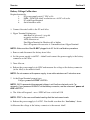
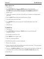
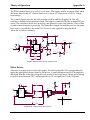
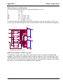
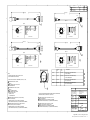
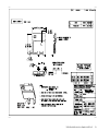
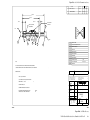
10. Attach the certified source of CO2 gas to the CO2 side-stream sampling tube as per
Figure 2-5 below.
Service Manual 6200-43E Rev. D
Welch Allyn Atlas Monitor 19
Section 2
Service
Adjust Regulator to
Approximately 2 psi
Water
Trap
Vent
CO2
Figure 2-5. Example of CO2 calibration setup.
CAUTION: IMPROPER USE,STORAGE OR HANDLING OF COMPRESSED
GAS VESSELS CAN CAUSE DEATH OR INJURY. FOLLOW GAS MANUFACTURES SAFETY PROCEDURES!
11. Adjust the CO2 regulator just enough to allow a small amount of gas to flow out of the
vent (approximately 2 psi).
12. Press the BP START/CANCEL button. The message: “Sampling” will appear on CRT.
“CO2 calibration successful” or “CO2 calibration failed” will appear on the CRT
display.
13. Press the TREND button to exit.
No-Load Battery Voltage Calibration
NOTE: No-Load Battery Voltage Calibration procedure is for models 622 and 623 only. If
you disconnect the battery you must reset time and date after you reconnect the battery.
Specifications: No load battery charge 6.85 VDC
Required materials: DVM
1. Remove the battery and disconnect the battery leads from the Atlas. Use the DVM to
measure across the connectors, red+ and black-.
2. Adjust the voltage to 6.85 VDC by turning potentiometer R338, located behind the right
battery jack. Turning clockwise will increase the no-load voltage and counter clockwise
will decrease the no-load voltage.
20 Welch Allyn Atlas Monitor
Service Manual 6200-43E Rev. D
Service
Section 2
Battery Voltage Calibration
Required materials.
1.
DC power supply rated: 7 VDC at 5A
2.
DMM / DVM with 10mV resolution on a 10 DC volt scale.
3.
PC with HyperTerminal
4.
Serial interface cable
1. Connect the serial cable to the PC and Atlas.
2. Hyper Terminal Settings are:
9600 Baud, 8 bit word, 1 stop bit
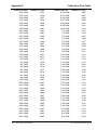
no parity, no flow control
ANSI character set
Find HyperTerminal in Windows 95 or higher
Start !Programs!Accessories ! Communication! HyperTerminal
NOTE: Make sure the Atlas IS NOT plugged into AC for this calibration procedure.
3. Remove and disconnect the battery from Atlas.
4. Set the power supply to 6.8VDC " 200mV and connect the power supply to the battery
connector on the Atlas.
5. Turn Atlas on..
6. Reduce the power supply to 6.0VDC and measure the voltage at the battery connector
(at the Atlas) to the nearest 10mV.
NOTE: Do not measure at the power supply, since cable resistance will introduce error.
7. At the HyperTerminal prompt type:
Pangea> power cal XXXX <ENTER>
NOTE: XXXX represents the measured voltage in millivolts no decimal point. For
example, if you measured 6.010VDC at the battery connector, use the command “power cal
6010 <ENTER>”.
8. The Atlas will respond: raw = ZZZZ mV true = 6010 mV OK
NOTE: ZZZZ is the raw uncalibrated reading that the instrument made.
9. Reduce the power supply to 5.6 VDC. You should soon hear the “low battery” alarm.
10. Measure the voltage at the battery connector to the nearest 10mV.
Service Manual 6200-43E Rev. D
Welch Allyn Atlas Monitor 21
Section 2
Service
11. At the HyperTerminal prompt type:
Pangea> power cal XXXX <ENTER>
NOTE: XXXX represents the measured voltage in millivolts with no decimal point. For
example if you measured 5.590 volts at the battery connector, then you would enter the
command “power cal 5590” <ENTER>.
12. The Atlas will respond:
raw = ZZZZmV true = 5590 OK
NOTE: ZZZZ is the raw uncalibrated reading that the instrument made.
13. Finish the calibration by typing:
Pangea> hw reset <ENTER>
NOTE: This will re-boot the Atlas.
14. Turn the Atlas off and reinstall the battery.
15. Reset time and date.
Printer Print Adjustment
1. Install new paper.
2. Turn Atlas on.
3. Attach an ECG simulator to Atlas and set simulator for a heart rate of 60 bpm, normal
sinus rhythm.
4. Press PRINT button. Evaluate the darkness of waveform and text printout.
5. If either need to be changed press DATE/TIME button then press LEAD SELECT button
to access Advanced Configuration menu.
6. Press SELECT button and scroll down to Printer Test Pattern. Then Press
HR ALARMS OFF button
7. Two lines will be displayed:
1.
Waveform+128
2.
Text+ 78
NOTE: These two numbers are the factory defaults and are a good starting point if the system is printing poorly or not at all.
22 Welch Allyn Atlas Monitor
Service Manual 6200-43E Rev. D
Service
Section 2
8. The left SET button controls the waveform darkness and the right SET button controls
the text darkness.
NOTE: Pressing the SET button up will increase the number and darken the waveform
while pressing the SET button down will decrease the number and will lighten the waveform.
9. Make changes to the printout as needed.
10. Press Trend button to return to waveform screen.
Temperature Calibration
Required Material:
1. PC with Windows7 95 or higher
2. Atlas serial cable
3. 1k Ohm, 1/2 watt precision resistor
4. 1/4O mono phono jack
5. Soldering iron and solder
6. Ohm Meter
1. Solder the 1 K Ohm resistor to 1/4” mono phono jack.
2. Measure the resistance at the tip of the phono jack. Record that resistance reading, to two
decimal points.
3. Plug the phono jack into the Atlas.
NOTE: The Atlas will show a temperature reading in the temperature display.
4. Start HyperTerminal on PC.
5. Hyper Terminal Settings are:
9600 Baud, 8 bit word, 1 stop bit
no parity, no flow control
ANSI character set
Find HyperTerminal in Windows7 95 or higher
Start !Programs ! Accessories ! Communication ! HyperTerminal
6. At the Pangea prompt Type: PANGEA> temp cal XXXXXX <ENTER>
NOTE: XXXXXX is the resistance reading you measured and recorded in milliohms at the
tip of the mono phono jack.
Example: If you measure 1000.40 ohms at the tip of the phono jack then you would type
temp cal 100040 <Enter>.
7. Wait four seconds then type: PANGEA> temp state <ENTER>. You will see a value
returned at the Pangea prompt.
Service Manual 6200-43E Rev. D
Welch Allyn Atlas Monitor 23
Section 2
Service
8. Verify that the resistance given by the above command returns a value " 0.5 ohms.
9. Verify temperature accuracy as outlined in Chapter 3, Table 3-2.
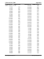
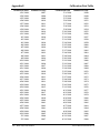
Calibration Date Set
NOTE: After calibrating the Atlas you must reset the calibration date. The calibration date
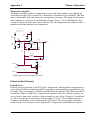
is the date you performed the calibration. The calibration date appears in the Service Mode
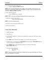
menu. See Figure 2-6 for an explanation of the Service screen.
1. At the Pangea prompt type.
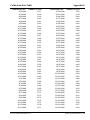
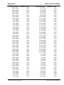
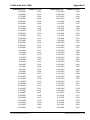
Pangea> nvram set cal_date XXXX <ENTER>
NOTE: XXXX is the number of days from January 1, 1998 until the present date. See
APPENDIX E for that number or calculate manually.
24 Welch Allyn Atlas Monitor
Service Manual 6200-43E Rev. D
Service
Section 2
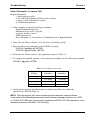
Explanation of an Atlas Service Screen
Service Mode
Select a test
Verify
f manomete
Reset to factory default
Battery test
Calibrate CO2
CRT test pattern
Printer test pattern
LED test
Button test
Display A/D channels
0.00
A
B
C
D
Model 220 with printer
Cal:27 Nov 2002
Sn: 62304064 Sw: BB.025000 Boot: AA.01.0000
SpO2: NELLCOR MP506 V1.8.0 6/21/02
CO2 1.0 V3.00 #2542 Cal: 27 Nov 2002 14 Nov 2002
Press the Trend button to exit
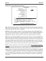
Figure 2-6. Example and Explanation of an Atlas Service Screen
Line A Indicates that the Atlas is a model 220 and that the Atlas has a printer. If the Atlas
did not have a printer then the text “with printer” would be absent. The date field following
indicates the date the Atlas was last calibrated.
Line B starts with a numeric sequence. The first three digits are the model number of the
Atlas. The next five numbers are the Atlas serial number. The next sequence,alphanumeric,
indicates what software version is currently loaded into the Atlas. The third sequence,
alphanumeric, indicates what version boot software is currently loaded into the Atlas.
Line C starts with the SpO2 OEM board used in the Atlas. There are two SpO2 OEM boards
used in the Atlas. One is Nellcor and the other is Nonin. The next sequence indicates the
model of the SpO2 board. The next sequence, that starts with a letter “V”, is the version software used with the current SpO2 board. The date following the SpO2 software is the date
the OEM loaded the software into the SpO2 board. SpO2 OEM software can not be upgraded.
If the most current software is needed, you will need to replace the SpO2 board.
Line D is the CO2 information if your Atlas has CO2 installed. Only models 623 have CO2
installed. If your Atlas does not have CO2 installed then line D will be absent. If your Atlas
has CO2 installed then line D will start with CO2 followed by a numeric number. That
numeric value is the software loaded into the CO2 board. The next alphanumeric sequence,
starting with a “V”, is the version of that software. The next numeric sequence starting with
a “#” is the serial number of the CO2 board. The next sequence, a date, is the date the CO2
was last calibrated. The last sequence, a date, is the date the CO2 was reset. CO2 OEM software can not be upgraded. If the current software is needed, you will have to replace the
CO2 board.
Service Manual 6200-43E Rev. D
Welch Allyn Atlas Monitor 25
Section 2
Service
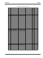
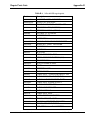
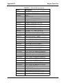
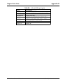
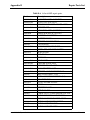
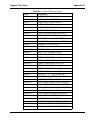
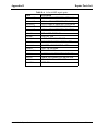
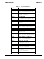
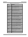
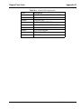
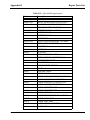
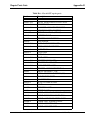
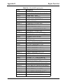
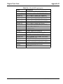
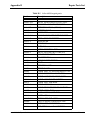
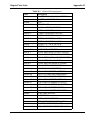
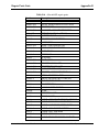
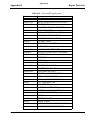
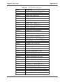
Table 2-3. Software Revision Table.
Model
621S0
621S0
621S0
621S0
Operating System
AA.01.4000, 9/8/99
BB.02.0000, 4/4/01
BB.02.2000, 6/4/02
BB.02.5000, 10/14/02
Boot loader
AA.01.0000,
AA.01.0000,
AA.01.0000,
AA.01.0000,
Nellcor
Nonin Pryon
V7
V7
V7
V7
6/20/99
6/20/99
6/20/99
6/20/99
621N0 BB.02.5000, 10/14/02 AA.01.0000, 6/20/99 V1.8.1.0, 10/14/02
621SP
621SP
621SP
621SP
AA.01.4000, 9/8/99
BB.02.0000, 4/4/01
BB.02.2000, 6/4/02
BB.02.5000, 10/14/02
AA.01.0000,
AA.01.0000,
AA.01.0000,
AA.01.0000,
6/20/99
6/20/99
6/20/99
6/20/99
V7
V7
V7
V7
621NP BB.02.5000, 10/14/02 AA.01.0000, 6/20/02 V1.8.1.0, 10/14/02
622S0
622S0
622S0
622S0
622S0
AA.01.4000, 9/8/99
BB.02.0000, 4/4/01
BB.02.2000, 6/4/02
BB.02.2000, 6/4/02
BB.02.5000, 10/14/02
AA.01.0000,
AA.01.0000,
AA.01.0000,
AA.01.0000,
AA.01.0000,
6/20/99
6/20/99
6/20/99
6/20/99
6/20/99
V7
V7
V7
V7
V7
622SP
622SP
622SP
622SP
AA.01.4000, 9/8/99
BB.02.0000, 4/4/01
BB.02.2000, 6/4/02
BB.02.5000, 6/14/02
AA.01.0000,
AA.01.0000,
AA.01.0000,
AA.01.0000,
6/20/99
6/20/99
6/20/99
6/20/99
V7
V7
V7
V7
622N0
622N0
622No
622N0
AA.01.4000, 9/8/99
BB.02.0000, 4/4/01
BB.02.2000, 6/4/02
BB.02.5000, 10/14/02
AA.01.0000,
AA.01.0000,
AA.01.0000,
AA.01.0000,
6/20/99
6/20/99
6/20/99
6/20/99
V
V
V
V
1.2.0.0
1.2.0.0
1.2.0.0
1.8.1.0
12/17/97
12/17/97
12/17/97
10/14/02
622NP
622NP
622NP
622NP
AA.01.4000, 9/8/99
BB.02.0000, 4/4/01
BB.02.2000, 6/4/02
BB.02.5000, 10/14/02
AA.01.0000,
AA.01.0000,
AA.01.0000,
AA.01.0000,
6/20/99
6/20/99
6/20/99
6/20/99
V
V
V
V
1.2.0.0
1.2.0.0
1.2.0.0
1.8.1.0
12/17/97
12/17/97
10/14/02
10/14/02
623SP
623SP
623SP
622SP
AA.01.4000, 9/8/99
BB.02.0000, 4/4/01
BB.02.2000, 6/4/02
BB.02.5000, 10/14/02
AA.01.0000,
AA.01.0000,
AA.01.0000,
AA.01.0000,
6/20/99
6/20/99
6/20/99
6/20/99
623NP
623NP
623NP
623NP
AA.01.4000, 9/8/99
BB.02.0000, 4/4/01
BB.02.2000, 6/4/02
BB.02.5000, 10/14/02
AA.01.0000,
AA.01.0000,
AA.01.0000,
AA.01.0000,
6/20/99
6/20/99
6/20/99
6/20/99
26 Welch Allyn Atlas Monitor
V7
V7
V7
V7
V
V
V
V
1.2.0.0
1.2.0.0
1.2.0.0
1.8.1.0
12/17/97
12/17/97
12/17/97
10/14/02
0.E V1.00
0.E V1.00
0.E V1.00
0.E V1.00
Service Manual 6200-43E Rev. D
Service
Section 2
Software Upgrade Procedure
NOTE: The following procedures are required to upgrade the software on a fully functioning Atlas or to reload software after replacing the CPU board. The download utility
“atlas_dl.exe” loads the following files automatically.
1. atlas.out.gz
2. nvram_common.txt
3. nvram_(model#).txt
4. nvram_(language).txt
“Atlas_dl.exe” will also query the Atlas to determine what model number the Atlas is and
what language to download.
Equipment or supplies required:
1. PC with Windows7 95 or higher
2. Atlas serial cable
3. File: atlas_dl.exe (Included in the Atlas Repair Software listed in Table2-2.)
NOTE: Make sure you have HyperTerminal turned off or the following utility download will
not work!
1. Run the program atlas_dl.exe from the CD or copy the file to your hard drive and run the
program from there.
2. Connect the serial cable between the Atlas and the PC s’“COM1 port”.
3. Turn your computer on and locate the “atlas_dl.exe” file.
4. Double left click on the “atlas_dl.exe” file.
5. When the file starts to download, the CRT will go blank on the Atlas.
NOTE: Do not use the computer while the program is downloading.
6. After down loading is complete, check all alarm settings and all user advanced
configuration settings since these are RESET by this utility software download
procedure.
NOTE: Stop here if you are just upgrading software on a fully functional Atlas monitor or if
you have replaced the CPU board.
NOTE: If you have replaced the MAIN BOARD then you MUST continue with the next
procedure (DOWNLOADING NVRAM FILES).
NOTE: Perform the following NVRAM downloading procedure if you have replaced the
MAIN BOARD. The NVRAM resides on Main Board.
Service Manual 6200-43E Rev. D
Welch Allyn Atlas Monitor 27
Section 2
Service
Down Loading NVRAM Files
Required Materials.
1. Computer with Windows7 95 or higher.
2. The latest Atlas repair software. Call your local Welch Allyn
representative.
1. Once you have procured the latest Atlas Repair Software, you will be able
to run the programs straight from the CD or copy the files to your hard drive.
NOTE: Through HyperTerminal you will need to load the following files:
1. nvram_cal_init.txt
2. nvram_common.txt
3. model# of Atlas
3.1.You will load “nvram200.txt” if your Atlas is a model 621xx.
3.2.You will load “nvram210.txt” if your Atlas is a model 622xx.
3.3 You will load “nvram220.txt” if your Atlas is a model 623xx.
4. “language.txt”Any combination of or all of the following files
4.1 “nvram_english.txt” for the English language
4.2 “nvram_french.txt” for the French language
4.3 “nvram_german.txt” for the German language
4.4 “nvram_spanish.txt” for the Spanish language
4.5 “nvram_potuguese.txt” for the Portuguese language
4.6 “nvram_italian.txt” for the Italian language
4.7 “nvram_chinese.txt” for the Chinese language
4.8 “nvram_japanese.txt” for the Japanese language
5. printer.txt (if fitted with a printer), or no_printer.txt. (if not fitted with a printer)
NOTE: After loading the preceding files you, must then type the following commands at
the Pangea prompt.
1. “nvram set serial xxxxx” where xxxxx is the serial number of the Atlas monitor.
2. “nvram write” writes the information to memory.
3. “hw reset” performs a hardware reset.
2. Connect the serial cable between the Atlas and the PC COM1 port.
3. Open HyperTerminal program on PC.
Hyper Terminal Settings are:
9600 Baud, 8 bit word, 1 stop bit
no parity, no flow control
ANSI character set
Find HyperTerminal in Windows7 95 or higher
Start !Programs ! Accessories ! Communication ! HyperTerminal
28 Welch Allyn Atlas Monitor
Service Manual 6200-43E Rev. D
Service
Section 2
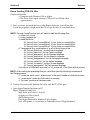
4. Turn Atlas on. You should see the Pangea prompt. See example in Figure 2-7.
Figure 2-7. Pangea prompt in HyperTerminal.
5. Scroll over to “Transfer” and then scroll down and choose “Send Text File”.
See example in Figure 2-8.
Figure 2-8. Choosing “Send Text File” in HyperTerminal.
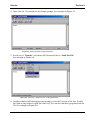
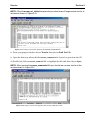
6. Another window will then appear and prompt you for the location of the files. Double
left click on that folder to open that directory. You can also run these programs from the
CD. See example in Figure 2-9.
Service Manual 6200-43E Rev. D
Welch Allyn Atlas Monitor 29
Section 2
Service
Figure 2-9. Choosing directory where NVRAM files are stored.
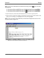
7. Once the folder is open, open the file “nvram_cal_init.txt” file by double left clicking on
that file or by high lighting the file and then click on the Open button. See example in
Figure 2-10.
Remember that after you have download the files in this section and you must
complete this entire “Downloading NVRAM files” section, that you must perform
a complete calibration on the Atlas monitor.
Figure 2-10. Choosing the nvram_cal_init.txt file.
30 Welch Allyn Atlas Monitor
Service Manual 6200-43E Rev. D
Service
Section 2
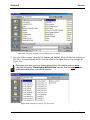
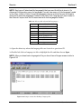
NOTE: After the nvram_cal_init.txt has executed you should see a Pangea screen similar to
window as shown in Figure 2-11.
Figure 2-11. Pangea screen after opening the nvram_cal_init.txt file.
8. From your pangea window choose Transfer then choose Send Text File.
9. Open the directory where the file nvram_common.txt is located or open from the CD.
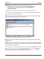
10. Double left click on nvram_comm.txt file or highlight the file and then choose Open.
NOTE: After opening the nvram_common.txt file you should see a screen similar to the
window shown in Figure 2-12.
Figure 2-12. Pangea screen after opening the nvram_common.txt file.
Service Manual 6200-43E Rev. D
Welch Allyn Atlas Monitor 31
Section 2
Service
NOTE: Next you will download the model# of the Atlas by choosing only one of the three
following files.
1. If you have an Atlas model 621 then you will only download the file nvram200.txt.
2. If you have an Atlas model 622 then you will only download the file nvram210.txt.
3. If you have an Atlas model 623 then you will only download the file nvram220.txt.
11. Open the directory where the model number files are located or open from CD.
12. Open the file by double left clicking on the file that represents the model number of the
Atlas you are working on or highlight that file then choosing Open.
NOTE: After opening the Atlas model# file you should see a Pangea screen similar to the
window as shown in Figure 2-13.
Figure 2-13. Pangea prompt after opening the model# file.
32 Welch Allyn Atlas Monitor
Service Manual 6200-43E Rev. D
Service
Section 2
NOTE: Next you will download the language(s) that you want the Atlas to store in it’s
Advanced Configuration menu for languages. You can have one or all the languages loaded
in the Atlas. Listed in Table 2-4 are the language(s) choices and the files you will need to
download to have the language(s) loaded in the Atlas. Each language you want loaded in
the Atlas will require that the file associated with that language be loaded.
Table 2-4. Files needed to download language(s).
Language
File needed to download
English
nvram_english.txt
French
nvram_french,txt
Spanish
nvram_spanish.txt
German
nvram_german.txt
Portuguese
nvram_portuguese.txt
Italian
nvram_italian.txt
Chinese
nvram_chinese.txt
Japanese
nvram_japanese.txt
13. Open the directory where the language files are located or open from CD.
14. Double left click on language.txt file or highlight the file and then choose Open.
NOTE: After you download a language.txt file you should see a Pangea screen similar to
Figure 2-14.
Figure 2-14. Pangea screen after loading a language file.
Service Manual 6200-43E Rev. D
Welch Allyn Atlas Monitor 33
Section 2
Service
NOTE: Next you tell the Atlas if it does or does not have a printer.
1. If the Atlas has a printer you will download the file nvram_printer.txt.
2. If the Atlas does not have a printer then you will download the file
nvram_no_printer.txt.
15. Open the directory where the printer.txt files are located or open from CD.
16. Double left click on the printer file or the no_printer file or highlight the printer file or
the no_printer file and then choose Open.
NOTE: After you have downloaded the printer or no_printer file you should see a Pangea
screen similar to the window as shown in Figure 2-15.
Figure 2-15. Pangea screen after downloading the nvram_printer.txt file.
NOTE: The next three commands will require that you actually type the command at the
Pangea prompt.
NOTE: XXXXX on line 17 is the Atlas 5 digit serial number. The serial number is located on
the bottom of the Atlas. Make sure that you have a space between the command serial and
the five numbers you are entering.
17. At the Pangea prompt type the following command “nvram set serial XXXXX”<ENTER>
NOTE: After you have typed the nvram set serial XXXXX command and hit ENTER you
should see a Pangea screen similar to the example in Figure 2-16.
34 Welch Allyn Atlas Monitor
Service Manual 6200-43E Rev. D
Service
Section 2
Figure 2-16. Pangea screen after you have downloaded the nvram set serial command.
NOTE: To finish downloading the NVRAM files, type the next two commands at the Pangea
prompt.
18. At the Pangea prompt type the command nvram write <ENTER>.
19. At the Pangea prompt type the command hw reset <ENTER>.
NOTE: The hw reset command will reboot the Atlas.
Remember that after you have download the files in this section and you must
complete this entire “Downloading NVRAM files” section, that you must perform
a complete calibration on the Atlas monitor.
NOTE: The firmware is not up grade able on the OEM boards (SpO2 and CO2) boards. If a
higher version software is needed, then you will need to replace the OEM board.
Service Manual 6200-43E Rev. D
Welch Allyn Atlas Monitor 35
Troubleshooting
Section 3
NOTE: Review customer complaint and determine if it is safe to plug in the Atlas monitor
into AC power and if it is safe to turn on!
Power on Self Test
1. Plug in Atlas into AC power with no sensors attached. Verify that the AC~ LED indictor
is lit. Install paper in printer if fitted.
2. Turn on power and verify the following:
1. Green light in power button.
2. Loud beep when Power On button pressed.
3. Three dashes in SYSTOLIC.
4. Three dashes in DIASTOLIC.
5. Two dashes in SpO2 (takes several seconds after BP dashes come on).
6. Three dashes in PULSE (takes several seconds after BP dashes come on).
7. Single bar at the bottom of Plethysmograph.
8. No lights in TEMP.
9. No lights in ALARMS OFF buttons.
10. X lit on AUTO.
11. CRT display may comes on slowly if cold or quickly if still warm from last use.
12. May see version string in center if comes on quickly. It is not a problem if not seen
because it comes on slowly.
3. On the CRT you should see:
1. Three dashes for Heart Rate
2. Heart symbol
3. Lead select symbol
4. Scale bar
5. One or two lines of dashes for waveforms – depends upon settings.
6. Three dashes for MAP – or blank, depending upon settings.
7. Error message(s) at bottom of screen?
4. On models 622 or 623, disconnect AC cable. You should see no change except the
AC~ LED indicator will not be lit. If you see warnings of a low, very low or depleted
battery, or if the system turns off by it’s self, plug the Atlas back into the AC outlet and
let the unit charge with unit turned off. Repeat test in 2 hours.
5. Plug the monitor back into AC.
Service Manual 6200-43E Rev. D
Welch Allyn Atlas Monitor 37
Section 3
Troubleshooting
Menu Functional Test
1. Press DATE/TIME button to enter menu page. Press TREND button to access the
Advanced Configuration menu.
2. Write down all configuration settings so that they can be reset to customer preferences
later. If you have a printer press the PRINTER button to print out customer configuration
settings.
3. Set language to your native tongue if necessary to allow you to write down the other
settings. The top item is always the language, press either SET buttons to step through
list.
4. Press TREND button to return to idle screen. Press DATE/TIME button and verify that
date and time are correct. Set date and time if necessary.
NOTE: An incorrect date may indicate a battery problem. If date was incorrect, turn off
unit, disconnect AC power cable, wait 5 minutes then reconnect the power cable. Turn Atlas
on. Check date again. If date comes back incorrect on model 621 then replace main board.
On model 622 and 623, if battery was not dead then replace main board.
5. Press DATE/TIME button to return to waveform screen if needed.
6. Press DATE/TIME button then press LEAD SELECT button to access service mode
7. Version/configuration data is in lower half of menu, write it all down.
8. Press SELECT button to highlight reset to factory defaults.
9. Press BP START/CANCEL button to reset configuration.
10. Press TREND button to return to idle screen.
11. Press DATE/TIME button then press TREND button to access the Advanced
Configuration menu.
12. Set language to your native tongue if necessary
NOTE: We have just reset the monitor to factory defaults. Compare settings to factory
defaults appropriate for the country in Operator manual. If the factory defaults do not
match then that may indicate a memory problem. Changing only the language should not
change any of the other factory default settings.
13. Press DATE/TIME button then press LEAD SELECT button to access service mode.
14. Press SELECT button to highlight CRT test pattern.
38
Welch Allyn Atlas Monitor
Service Manual 6200-43E Rev. D
Troubleshooting
Section 3
15. Press BP START/CANCEL button to show test pattern. Examine display. Press any key to
end display.
16. Press Select button to highlight Printer test pattern (if fitted). Press BP START/CANCEL
button to start test pattern. Printer should print a test pattern. Press any key to end
display. Examine printout.
17. Press SELECT button to highlight LED test. Press AUTO button to turn on all LEDs.
Press BP START/CANCEL button to show automatic test pattern. Watch for a while,
look for glitches in pattern. Press SET button to go to manual mode and step through
individual segments if needed to observe a problem.
18. Press SELECT button to highlight Button test. Press BP START/CANCEL button to
start test. Press every button on system, press BP START/CANCEL button last.
Verify that buttons match up with their names and that all buttons are functional.
NOTE: If name does not correspond to the button pushed then this may indicate memory
corruption. You may need to replace the main board.
19. Press SELECT button to highlight Display A/D channels. Press SET button and write
down all values for each of the four screens for later review. Press TREND button to
return to Idle screen.
Service Manual 6200-43E Rev. D
Welch Allyn Atlas Monitor 39
Section 3
Troubleshooting
BP Test
1. Press DATE/TIME button then press TREND button to access the Advanced
Configuration menu. Press SELECT button to highlight Initial pressure. Press SET button
to change Initial pressure to 280 mmHg. Press SELECT button to highlight MAP. Press
SET button to change MAP to Yes. Press TREND button to return to idle screen.
2. Connect the BP port to the BP simulator. Set the simulator for a normal reading
(140/80, 100BPM, NSR). Press BP START/CANCEL button. Atlas should start to
pump and display a manometer value in SYSTOLIC LED. This value should track
and be very close to pressure displayed by manometer on BP simulator (if fitted).
Largest number shown in SYSTOLIC LED should be very close to the initial pressure
setting recorded above from Advanced Configuration. System should start stepping
down pressure, showing step values in SYSTOLIC LED display. It then should display
the correct SYSTOLIC and DIASTOLIC values. System may show MAP value depending
upon country language setting.
3. Press BP START/CANCEL button. System should start pump, display manometer
value in SYSTOLIC LED. This value should track and be very close to pressure
displayed by manometer in BP simulator (if fitted). Largest number shown in
SYSTOLIC should be very close to the Initial pressure setting of 280 mmHg. If
pressure shown exceeds 300 mmHg then re calibrate the Atlas BP.
4. System should start to step down pressure, showing step values in SYSTOLIC LED and
then display correct SYSTOLIC and DIASTOLIC values. System should show MAP
value. MAP value should match what is shown by simulator.
5. Set simulator to (120/70, 60 (beats per minute)bpm, NSR).
6. Press the AUTO button. The X manual BP cycle indicator will go out and the 1 minute
auto BP cycle indicator will flash for 10 seconds. 20 seconds after the 1 minute auto BP
cycle indicator stops flashing, BP measurement starts.
7. Verify the BP reading. If BP measurement incorrect recalibrate.
8. No less than 30 seconds after completing the measurement another measurement
should start. While it is pumping up, press the BP START/CANCEL button.
Measurement should stop immediately and pressure should be dumped (as seen on
the simulator manometer).
9. Press AUTO button and X manual BP cycle indicator should light (not flashing).
10. Disconnect the tubing from the BP port on the Atlas. Press BP START/CANCEL
button and note the time (to the second) when the Atlas aborts the BP cycle and gives
you an alarm. It should take no longer than 1 minute. Turn Atlas off.
40
Welch Allyn Atlas Monitor
Service Manual 6200-43E Rev. D
Troubleshooting
Section 3
Static Manometer Accuracy Test
Required materials.
1. Serial interface cable
2. PC with HyperTerminal (Windows 95 or above)
3. 500cc vessel with inflation system.
4. Calibrated manometer
1. Turn computer on and activate Hyper terminal.
Hyper Terminal Settings are:
9600 Baud, 8 bit word, 1 stop bit
no parity, no flow control
ANSI character set
Start !Programs ! Accessories ! Communication ! HyperTerminal
2. Turn Atlas on. Refer to Figure 2.1 in Section 2 for inflation setup.
3. Enter the following commands at the PANGEA> prompt.
PANGEA> bp safety off <ENTER>
PANGEA> bp valve close <ENTER>
4. Pressurize the Atlas monitor to the applied pressures in Table 3-1.
5. To compare the applied pressure to the transducer readings use the following command.
PANGEA> bp press <ENTER>
Table 3-1. Transducer pressure table.
Applied
Pressure
Primary
Transducer
Safety
Transducer
0 mmHg
"0.75 mmHg
"1.5 mmHg
"1.5 mmHg
"1.5 mmHg
"1.0 mmHg
"1.5 mmHg
"4.5 mmHg
"7.5 mmHg
50 mmHg
150 mmHg
250 mmHg
6. Verify that the primary transducer and secondary transducer are within the
specifications listed in Table 3-1.
NOTE: The Atlas monitor will return a response to the computer screen as follows.
If you tested at the 50mmHg pressure you would receive a message similar to: px = 5279,
sx = 5305 x 0.01. Where px is the primary transducer and 5279 = 52.79 mmHg and sx is the
secondary transducer and 5305 = 53.05 mmHg.
Service Manual 6200-43E Rev. D
Welch Allyn Atlas Monitor 41
Section 3
Troubleshooting
BP Leak Test
NOTE: Unit must not leak more than 5 mmHg in a 15 second interval while attached to a
100cc test cavity pressurized at 50 mmHg, 150 mmHg and 250 mmHg.
Required Materials: 100cc test vessel (+10cc/-0cc), stopwatch, squeeze bulb, calibrated
manometer.
1. Connect Atlas to 100cc test vessel and calibrated manometer as shown in Section 2,
Figure 2.1.
2. Turn Atlas on.
3. Press DATE/TIME button then press LEAD SELECT button to access the Service Mode.
4. Press SELECT button and choose Verify manometer.
5. Pressurize the Atlas with squeeze bulb to 50mmHg and allow reading to stabilize.
6. Observe pressure for 15 seconds.
6. Unit should not leak more than 5mmHg during this time.
7. Repeat this process at 150mmHg and 200mmHg.
Over 15 mmHg Test
NOTE: Atlas hardware must detect if the pneumatic system has been pressurized greater
than 15 mmHg for more than 155 seconds but less than 180 seconds.
Required Materials: 500cc test vessel (+10cc/-0cc), stopwatch, squeeze bulb, calibrated
manometer.
1. Connect Atlas to 500cc test vessel and calibrated manometer as shown in Section 2,
Figure 2.1.
2. Turn Atlas on. Press DATE/TIME button then press LEAD SELECT button to access the
Service Mode. Press SELECT button and choose Verify manometer.
3. Pressurize the Atlas with squeeze bulb to any pressure above 15 mmHg and maintain
that pressure during the test. Start the stop watch.
4. Verify that the valve opens and pressure drops between 155 seconds and 180 seconds.
5. Turn Atlas off.
42
Welch Allyn Atlas Monitor
Service Manual 6200-43E Rev. D
Troubleshooting
Section 3
BP Dump Verification Test
1. Connect the Atlas to a 500 cc vessel as shown in Section 2, Figure 2.1.
2. Turn Atlas on.
3. Press DATE/TIME button then press LEAD SELECT button to access the Service Mode.
4. Select Verify manometer.
5. Pressurize the Atlas to just over 260 mmHg.
6. Allow reading to stabilize for 15 seconds.
7. Ensure the reading is still over 260 mmHg.
8. Start the stop watch when you press the SELECT button. When the SELECT button is
pressed the Atlas will start a pressure dump.
9. Verify that the pressure drops to below 15 mmHg within 10 seconds.
Hardware Fail Safe Tests
NOTE: Atlas hardware must detect over pressure on unit pneumatic system between 296.0
mmHg and 330.0 mmHg.
1. Connect the Atlas for testing as shown in Section 2, Figure 2.1
2. Turn Atlas on.
3. Press CLOCK/DATE button then press LEAD SELECT button to access Service Mode.
4. Press SET button to highlight the Manometer.
5. Pump system up and record at what pressure the Atlas dumps.
Service Manual 6200-43E Rev. D
Welch Allyn Atlas Monitor 43
Section 3
Troubleshooting
ECG/Respiration Test
NOTE: Simulator should support ECG impedance respiration.
1. Cycle power on Atlas, connect a 5 lead ECG cable set to the simulator. Configure the
simulator for NSR, 100 bpm and set the impedance respiration rate to 20.
2. Press DATE/TIME button then press TREND button to access Advanced Configuration
menu.
3. Press SELECT button to highlight ECG lead set and press SET button to select 5 wire.
4. Set ECG gain to Automatic, ECG speed to 25mm/s, ECG bandwidth to Monitor, Second
trace selection to ECG.
5. Press TREND button to return to idle screen.
6. Verify you see: 1. ECG cascading onto second line
2. Scale bar on top left of CRT
3. Heart rate displayed as set on simulator
4. Lead Selected = II
5. Pulse tone high pitched
7. Press LEAD SELECT button and step through each of the lead settings.
(I,II,III,aVR,aVL,aVF,V)
8. Verify that you see a different ECG waveforms for each lead selected.
Heart Rate will go to dashes and alarms on some leads.
9. Set lead selected to II.
10. Press DATE/TIME button then press TREND button to access Advanced Configuration
menu.
11. Change Second trace selection to Respiration. Press TREND button to return to idle
screen.
12. Verify that you see:
1. ECG on top line
2. Scale bar on left of top line
3. Heart rate displayed as set on simulator
4. Lead Selected = II
5. Pulse tone high pitched
6. Respiration trace on second line and rate as set on simulator
7. Respiration rate displayed on CRT as set on simulator.
13. Disconnect ECG simulator.
44
Welch Allyn Atlas Monitor
Service Manual 6200-43E Rev. D
Troubleshooting
Section 3
SpO2 Test
1. Turn SpO2 alarms on.
2. Connect SpO2 cable to simulator.
3. Set simulator pulse rate to 60 beats/minute and verify that pulse rate is 60
±3 beats/minute or 3%, whichever is greater.
4. Set SpO2 between 70% and 100% and verify that SpO2 is accurate ±2 digits.
Temperature Test
1. Without anything connected to the temperature connector on the Atlas, verify that the
temperature LED is blank.
2. Using Table 3-2 below, connect the resistors to a 1/4 inch male mono plug and verify
temperature readings.
Table 3-2 Resistor and temperature reference.
3. Connect the temperature probe to the Atlas monitor. You should see the display read
room ambient temperature. Disconnect the probe and verify you see dashes is the
display and that there are no alarms.
CO2 Functional Test
1. Press DATE/TIME button then press TREND button to access Advanced Configuration
menu
2. Set Second trace selection to CO2.
3. Press TREND button to return to idle screen.
4. Insert watertrap with tubing attached.
Service Manual 6200-43E Rev. D
Welch Allyn Atlas Monitor 45
Section 3
Troubleshooting
5. Verify that you: 1. Hear pump motor start.
2. See solid line waveform on lower trace.
3. See dashes in Respiration Rate.
4. See dashes in mmHg (or % or kPa, as configured).
6. Breathe gently and repeatedly over end of tubing.
7. Verify that you:
1. See waveform within seconds of breathing.
2. See respiration rate non zero within one minute.
3. See CO2 concentration non zero within one minute.
Battery Functional Test
1. System must have been plugged in for 24 hours to guarantee that the battery is fully
charged. But, for now we can do a functional test as follows.
2. Press DATE/TIME button then press LEAD SELECT button to access Service Mode
menu.
3. Press SELECT button to highlight Battery test.
4. Verify that the menu reports: 1. Battery Low Time XXX
2. Battery Dead Time YYY
NOTE: These are the results from the last battery test. The Battery Low Time is the time in
hours and minutes that the battery ran in the last test until the Low Battery alarm started,
and the Battery Dead Time is the time from the beginning of the Low Battery Alarm until the
system turned itself off when the battery voltage reached the cutoff level.
NOTE: 2:08 means 128 minutes which is the default setting indicating a battery test has
never been made before.
5. Write down the Battery Low Time and Battery Dead Time.
6. Unplug AC cord to start battery test.
7. The timers will begin the moment you unplug the AC cord. Leave the system on until it
powers down by itself automatically. Plug Atlas into AC and turn the Atlas on, enter the
Service Mode menu, select Battery Test again, and write down the new values. Compare
these to the previous values, and to the minimum specification:
1. Battery Low Time = 1 Hour
2. Battery Dead Time = 10 Minute minimums
8. Replace the battery if performance falls below specification.
46
Welch Allyn Atlas Monitor
Service Manual 6200-43E Rev. D
Troubleshooting
Section 3
Printer Functional Test
NOTE: Configuration settings for printing are different for text pages than for waveforms.
1. Connect ECG simulator to generate a sample waveform.
2. Press PRINT button and look at waveform printout. Look for darkness, thickness of
lines, legibility of text, blurring, “blooming” of text.
3. If waveform or printed text needs to be darker or lighter, go to Section 2, page 10 for
printer calibration.
Print on Alarm Test
1. Turn the Atlas on.
2. Press the DATE/TIME button then press the TREND button to access Advanced
Configuration menu. Press the SELECT button and scroll down to Print on Alarm. Press
the SET button and set Print on alarm to No.
3. Connect an ECG simulator to the Atlas. Set the ECG rate on the simulator to 60 bpm,
normal sinus rhythm.
4. Press left SELECT button and the HI heart rate alarm parameter will flash. Set the high
heart rate alarm to 110 bpm on the Atlas and press the SELECT button again and the low
heart parameter will flash. Press SELECT button one more time to return to the default
screen.
5. Set the ECG simulator to heart rate to 120 bpm.
6. Verify that you hear the audio alarm and that the printer is not printing.
7. Set the ECG simulator to 60 bpm and make sure that the alarm condition has cleared.
8. Press the DATE/TIME button then press the TREND button to access Advanced
Configuration menu. Press the SELECT button and scroll down to Print on Alarm. Press
the SET button and set Print on alarm to Yes.
9. Set the ECG simulator to 50 bpm.
10. Verify that the printer printed a 15 second strip.
Software/Firmware
1. Review versions written down earlier and compare to latest available. Make sure that all
components are compatible with each other. See section 2, page 26, Table 2-3.
Service Manual 6200-43E Rev. D
Welch Allyn Atlas Monitor 47
Section 3
Troubleshooting
ECG Alarms Test
1. Turn the Atlas on. Verify that you hear the power on tone.
2. Press DATE/TIME button then press TREND button to access Advanced Configuration
menu. Press SELECT button and scroll down to Second Trace. Press SET button and set
the second trace to ECG.
3. Connect ECG simulator to the Atlas. Set the ECG rate on simulator to 60 bpm,
normal sinus rhythm.
4. Verify you hear the heart rate beep at a constant high pitch.
5. Press SpO2 - + button “-“ 8 times. Should get quieter and finally silent.
6. Press DATE/TIME button then press PRINT button to save settings.
7. Turn system off and back on.
8. Verify pulse tone is silent even though heart rate is shown.
9. Press SpO2 volume button “+” 8 times. Should get audible tone and then louder.
10. Disconnect ECG cable.
11. Verify you hear audio alarm and see error message “ECG Lead fault” and that you see the
three LED bars flash where the heart rate was on the CRT.
12. Press HR ALARMS Off button.
13. Verify that the audio alarm stops and that the visual alarm on the CRT remains.
14. Press HR ALARMS OFF button. Connect ECG simulator to the Atlas and set simulator
to normal sinus, 60 bpm.
15. Press left SELECT button and the HI heart rate alarm parameter will flash. Set the high
heart rate alarm to 55 bpm on the Atlas and press the SELECT button again and the low
heart parameter will flash. Press SELECT button one more time to return to the default
screen.
16. Verify that you hear the audio alarm and that you see the numeric value flashing in
the upper right portion of the monitor.
17. Return the high alarm limit to 120 bpm and press SELECT button. Verify the
audio alarm should is silent and the numeric visual alarm is flashing.
18. Press SELECT button twice. Verify the numeric low alarm parameter is flashing.
48
Welch Allyn Atlas Monitor
Service Manual 6200-43E Rev. D
Troubleshooting
Section 3
19. Set the LOW alarm for 65 bpm by pressing the up SET button. Press SELECT
button.
20. Verify that you hear the audio alarm and that you see the numeric value is flashing in
the upper right portion of the monitor.
21. Turn the Atlas off.
Service Manual 6200-43E Rev. D
Welch Allyn Atlas Monitor 49
Section 3
Troubleshooting
Respiration Alarms Test
1. Turn Atlas on.
2. Press DATE/TIME button then press TREND button to access Advanced Configuration
menu. Press SELECT button to scroll down to Second Trace. Press SET button and set
second trace to respiration. Press TREND button to return to default screen.
3. Set respiration on simulator to 20 respirations/minute and connect to the Atlas.
4. Press left SELECT button three times and set the hi respiration alarm to less than 20.
Wait 10 seconds and the CRT will return to the default screen.
5. Verify that you hear the audio alarm and that the respiration numeric value on the CRT
is flashing.
6. Press CO2/RESP ALARMS off button.
7. Verify that the audio alarms are silent, the visual numeric alarm is flashing and
that the red LED in the CO2/RESP ALARM off button is lit.
9. Press left SELECT button three times to access hi respiration alarms and set hi alarm to
30.
10. Wait ten seconds and the CRT will return to the default screen.
11. Press CO2/RESP ALARM off BUTTON then press left SELECT button four times to
access low respiration alarms and set low respiration alarms to 25.
12. Wait 10 seconds and CRT will return to the default screen.
13. Verify that you hear the audio alarm and that the respiration numeric value on the CRT
is flashing.
14. Press CO2/RESP ALARMS off button.
15. Verify that the audio alarms are silent, the visual numeric alarm is flashing and
that the red LED in the CO2/RESP ALARM off button is lit.
16. Turn Atlas off.
50
Welch Allyn Atlas Monitor
Service Manual 6200-43E Rev. D
Troubleshooting
Section 3
SpO2 Alarm Test
1. Turn Atlas on.
2. Attach SpO2 to a simulator and set for 95% SpO2.
3. Verify that you hear a pulse rate beep and that it is a different pitched tone than the
ECG pulse beep.
4. Change SpO2% setting on the simulator. Verify that tone changes pitch up or down
tracking simulator setting.
5. Press lower far right SELECT button until SpO2 LO is flashing, press right SET button
UP to change SpO2 LO setting to 99.
6. Wait until the SpO2 LO LED stops flashing.
7. Verify that you hear the SpO2 LO limit alarm.
8. Press Alarm Volume button “-“ eight times. Verify tones gets quieter but not silent.
9. Press Alarm Volume button “+“ eight times. Verify the tone gets louder.
10. Disconnect SpO2 cable from simulator and verify that the visual alarm “SpO2 cable
not detected” is displayed on the bottom left side of CRT. Verify that you hear the
audio alarm.
11. Press SpO2 ALARMS Off button.
12. Verify that the audio alarm sound is silent, that you do not see the visual alarm
message “SpO2 cable not detected” on the CRT and that the LED in the SpO2
ALARMS OFF button is on.
13. Turn Atlas off.
14. Disconnect SpO2 cable from Atlas.
Service Manual 6200-43E Rev. D
Welch Allyn Atlas Monitor 51
Section 3
Troubleshooting
Silence Alarm Test
1. Turn Atlas on.
2. Press DATE/TIME button then press TREND button to access Advanced
Configuration menu. Press SELECT button until Silence Duration is highlighted.
Press SET button until 90 seconds is highlighted. Press TREND button to go to
default screen.
3. Connect ECG simulator to the Atlas. Set the ECG rate on simulator to 60 bpm, normal
sinus wave.
4. Press left SELECT button once and set the HI alarm to 55 bpm.
5. Wait until you hear the audio alarm.
6. Press SILENCE button and start stopwatch. Verify that the alarm returns at 90
seconds.
7. Turn Atlas off.
CO2/RESP Test
1. Turn Atlas on.
2. Press DATE/TIME button then press TREND button to access the Advanced
Configuration menu.
3. Set Second trace selection to CO2.
4. Press TREND button to return to idle.
5. Insert CO2 watertrap with hose.
6. Breath into hose until a waveform is displayed.
7. Remove CO2 watertrap .
8. Verify you hear the audio alarm and that you see in the visual alarm “ CO2 watertrap not
detected” in the bottom left portion of CRT.
9. Press the “ CO2/RESP ALARMS off ” button. Verify that the audio alarm goes silent, the
visual alarm goes out and the red LED in the CO2/RESP ALARMS off button is lit.
10. Turn Atlas off.
52
Welch Allyn Atlas Monitor
Service Manual 6200-43E Rev. D
Troubleshooting
Section 3
Blood Pressure Alarm Test
1. Turn Atlas on.
2. With no hose connected to the BP port, press BP Start/Cancel button.
3. Place finger over BP port. This will block the flow causing the Atlas to detect an over
pressure.
4. Verify that you hear the audio alarm, that the visual alarm “ Check Blood Pressure Cuff “
appears in the lower left portion of the CRT and that the SYSTOLIC and DIASTOLIC
LED displays are flashing.
5. Press the BP ALARMS OFF button.
6. Verify the audio alarm is silent, the visual alarms have turned off and that the red LED in
the BP ALARMS OFF button is lit.
7. Press the BP ALARMS OFF button then press the BP START/CANCEL button twice.
8. Press BP START/CANCEL button and let Atlas run without anything attached to the BP
port.
9. Verify at 60 seconds that you hear the audio alarm and that the visual alarm “ Check
Blood Pressure Cuff “ appears in the lower left portion of the CRT and that the SYSOLIC
and DIASTOLIC LED displays are flashing.
10. Press the BP ALARMS OFF button.
11. Verify the audio alarm is silent, the visual alarms are still off and that the red LED in
the BP ALARMS OFF button is lit.
12. Press the BP ALARMS OFF button then press the BP START/CANCEL button twice.
13. Connect a BP simulator to the Atlas BP port. Set the simulator for a normal reading
(140/80, 100 bpm, normal sinus rythym).
14. Press the right SELECT button twice and the current SYSTOLIC HI alarm value will be
flashing.
15. Press the SET button to set SYSTOLIC HI alarm to 130.
16. Press BP START/CANCEL button.
17. Verify that you hear the audio alarm and that the numeric value in the SYSTOLIC LED
display is flashing.
Service Manual 6200-43E Rev. D
Welch Allyn Atlas Monitor 53
Section 3
Troubleshooting
18. Press the BP ALARMS OFF button.
19. Verify the audio alarm is silent, the numeric value in the SYSTOLIC LED display is still
flashing and that the red LED in the BP ALARMS OFF button is lit.
20. Reset the SYSTOLIC HI alarm to 200 (factory default). Press BP ALARMS OFF button.
21. Press the right SELECT button three times and the numeric value in the SYSTOLIC LO
alarm LED display will be flashing.
22. Press the SET button to set the SYSTOLIC BP LO alarm to 160.
23. Press BP START/CANCEL button.
24. Verify that you hear the audio alarm and that the numeric value in the SYSTOLIC LED
display is flashing.
25. Press the BP ALARMS OFF button.
26. Verify the audio alarm is silent, the numeric value in the SYSTOLIC LED display is still
flashing and that the red LED in the BP ALARMS OFF button is lit.
27. Reset SYSTOLIC LO alarm to 70 (Factory default). Press BP ALARMS OFF button.
28. Press right SELECT button four times and the numeric value in DIASTOLIC HI alarm
LED display will be flashing.
29. Press the SET button and set DIASTOLIC HI alarm to 70.
30. Press BP START/CANCEL button.
31. Verify that you hear the audio alarm and that the numeric value in the DIASTOLIC HI
LED display is flashing.
32. Press the BP ALARMS OFF button.
33. Verify the audio alarm is silent, the numeric value in the DIASTOLIC LED display is still
flashing and that the red LED in the BP ALARMS OFF button is lit.
34. Reset DIASTOLIC hi alarm to 155 (Factory Default).
35. Press right SET button five times and the numeric value in the DIASTOLIC LO alarm
LED display will be flashing.
36. Press SET button and set DIASTOLIC LO alarm to 90. Press BP ALARMS OFF button.
37. Press BP START/CANCEL button.
54
Welch Allyn Atlas Monitor
Service Manual 6200-43E Rev. D
Troubleshooting
Section 3
38. Verify that you hear the audio alarm and that the numeric value in DIASTOLIC LED
display is flashing.
39. Press the BP ALARMS OFF button.
40. Verify the audio alarm is silent, the numeric value in the DIASTOLIC display is still
flashing and that the red LED in the BP ALARMS BUTTON is lit.
41. Reset DIASTOLIC LO alarm to 50 (Factory Default).
42. Turn Atlas off.
Service Manual 6200-43E Rev. D
Welch Allyn Atlas Monitor 55
Section 3
Troubleshooting
Table 3-3. Atlas trouble shooting.
Failures
Possible Solutions
Power on:
Unit does not power up, no AC on LED,
no Power on LED.
Unit does not power up - AC and Power
on LED on.
Unit powers up intermittently or Power
button sticks or cannot duplicate power
on problem But unit passes burn in.
Unit powers up - but no image on CRT.
56
Welch Allyn Atlas Monitor
1
Check AC power cord.
2
Verify connection from power supply to main
board.
3
Verify +12V output from power supply.
4
Replace Power Supply.
5
Check Cable from main board to display board.
6
Replace Display board.
1
Check that the CPU board is fully seated.
2
Replace CPU board.
3
Check for conformal coating in J4 header - replace
board if coating is found.
4
Replace Main board.
5
Replace Display board.
1
Remove flashing on Bezel at power button.
2
Check for severely tipped power button LED on
display board.
1
Check for conformal coating in J4 header - replace
board if coating is found.
2
Replace CPU board.
3
Check for correct installation of connection from
main board to deflection board. If installed with
pin 1 in the pin 2 socket deflection board will be
damaged. If installed with pin 1 out of socket
deflection board will be OK.
4
Replace CPU assembly.
Service Manual 6200-43E Rev. D
Troubleshooting
Section 3
Table 3-4. Atlas trouble shooting.
Failures
Possible Solutions
Display:
Segment out, LED out, Buttons do not
work.
1
Replace Display board.
All or most segments stay on at power
up.
1
Replace CPU board.
2
Check cable from Display board to Main board.
3
Replace Power Supply.
CRT image rotated or poor alignment.
1
Rotate yoke and/or adjust magnets.
Only see a dot in the center of the
screen.
1
Check cable from yoke to CRT board.
Only see a horizontal line in the center
of the screen.
1
Check cable from yoke to CRT board.
2
Replace Deflection board.
1
Check flex-cable from Deflection board to tube.
2
Check high voltage anode connection.
3
Replace Deflection board.
4
Replace tube.
5
Replace CPU board.
1
Check for conformal coating in J4 header - replace
board if coating is found.
2
Replace CPU board.
1
Replace CPU board.
CRT:
No image - CRT to Main board
connection OK.
No image - Glow at bottom of screen.
Dark vertical scan lines in image.
Service Manual 6200-43E Rev. D
Welch Allyn Atlas Monitor 57
Section 3
Troubleshooting
Table 3-5. Atlas trouble shooting.
Failures
Possible Solutions
Printer:
Motor does not run.
Motor runs or chatters - paper does not
advance.
Light print or no print.
Prints gibberish.
58
Welch Allyn Atlas Monitor
1
Check that the unit is configured for printer. (CRT
image will freeze for 10 seconds if configured for
no printer.)
2
Check cable from printer PCB to motor.
3
Check cable from printer PCB to Main board.
4
Check motor gear alignment to first plastic gear.
5
Check for paper jam.
6
Replace printer PCB.
7
Replace CPU.
1
Check for missing dowel pin in roller.
2
Check for missing bearings/gears.
3
Replace printer PCB.
4
Replace CPU.
1
Check that paper is properly installed (thermal
side visible).
2
Check cable from printer PCB to print head.
3
Check printer-strobe-width in NVRAM (could
indicate error in printer thermistor circuit). If low,
check printer PCB, Main board, and CPU board.
4
Check mechanical assembly for proper force of
printhead on paper.
1
Reseat CPU board.
2
Replace CPU board.
3
Replace Printer to Main board cable.
4
Replace printer PCB.
Service Manual 6200-43E Rev. D
Troubleshooting
Section 3
Table 3-6. Atlas trouble shooting.
Failures
Possible Solutions
Safety:
Earth resistance over limit.
1
Check ground wire from motor to power supply
can.
2
Tighten screws that attach ground tabs to power
supply can.
3
Tighten screws holding power supply PCB to can.
4
Tighten quick connects on AC harness to power
supply.
5
Replace power supply PCB.
1
Run individual test. If unit passes repeat all tests.
2
Check seals @ tubing in BP assembly.
3
Check for lifted pins on the CPU connector JP8.
4
Replace Check valve.
1
Verify unit can pump beyond 300 mmHg then:
Retest.
2
If pump will not reach 300 mmHg, then:
A. Check for correct direction on check valve.
B. Check for possible leaks.
C. Check for pinched tubing.
D. Replace pump.
1
Verify unit can pump beyond 300 mmHg then:
Retest.
2
If pump will not reach 300 mmHg, then:
A. Check for correct direction on check valve.
B. Check for possible leaks.
C. Check for pinched tubing.
D. Replace pump.
3
Check for lifted pins on the CPU connector JP8.
Blood Pressure:
Leak test - Fails Leak Specification
Leak test - ‘Can’t pump beyond xxx.xx’.
Manometer Accuracy - ‘Can’t pump
beyond xxx.xx’.
Service Manual 6200-43E Rev. D
Welch Allyn Atlas Monitor 59
Section 3
Troubleshooting
Table 3-7. Atlas trouble shooting.
Failures
Possible Solutions
Manometer Accuracy - Fails Accuracy
Specification.
1
Replace Main board. Faulty transducer or amp.
Deflation Profile.
1
Replace dump valve.
2
Replace Main board. Valve drive circuitry fault.
1
Verify unit can pump beyond 300 mmHg then:
Retest.
2
If pump will not reach 300 mmHg then:
A. Check for correct direction on check valve.
B. Check for possible leaks.
C. Check for pinched tubing.
D. Replace pump.
1
Replace Main board. Fault with pressure
transducer, amplifier, or comparator.
2
Replace CPU board.
1
Replace Main board. - Fault with 15 mmHg detect
circuit.
2
Replace CPU board. - Fault with timer.
1
Replace Main board- If fault with 15 mmHg detect
circuit.
2
Replace CPU board.
Overpressure Limit - ‘Can’t pump
beyond xxx.xx’.
Overpressure Limit - Fails Accuracy
Specification.
Dwell time.
Dwell Pressure.
60
Welch Allyn Atlas Monitor
Service Manual 6200-43E Rev. D
Troubleshooting
Section 3
Table 3-8. Atlas failure trouble shooting.
Failures
Possible Solutions
SpO2:
No Signal - SpO2 fault message on CRT.
SpO2 signal accuracy.
1
Plug in finger cuff, connect to your finger & check
for function. If function is normal retest. If not
continue to step 2.
2
Check cables - SpO2 board to Main board, SpO2
board to Bezel.
3
Replace Main board.
4
Replace SpO2 board.
5
Replace CPU board.
1
If Nellcor, check ribbon cable and harness. Replace
as needed.
2
Replace SpO2 board.
1
Perform calibration. If that does not fix then go to
step 2.
2
Replace Pryon board.
1
Check for broken switch in trap receptacle.
2
Verify board ID in service module.
3
Perform functional test of ETCO2. Verify pump
comes on when switch in water trap receptacle is
activated. If switch is intermittent replace the
receptacle.
4
Replace Pryon board.
5
Replace CPU board.
1
Check connection - main board to temperature
jack.
2
Check pins in Temperature harness for correct
seating.
3
Replace Main board.
ETCO2:
Specification limits fail - Flow rate or
Percentage.
ETCO2 failure.
Temperature:
Service Manual 6200-43E Rev. D
Welch Allyn Atlas Monitor 61
Section 3
62
Welch Allyn Atlas Monitor
Troubleshooting
Service Manual 6200-43E Rev. D
Disassembly and Repair
Section 4
About Section 4
This section is a guide for disassembly and reassembly of the Atlas Monitor. Always refer to
current revision schematics, diagrams and final safety test procedures before attempting to
service this device.
Do not attempt to service this instrument unless you have received Service Training from
Welch Allyn or an authorized Training Agent, and are equipped with approved processes
and test equipment. For more information about training call the Welch Allyn Customer
Service phone number listed in Section 1 of this manual.
General:
The outside housing is removable in order to provide full access to all internal printed circuit boards and other components. Most of these are held in position with the surrounding
“E-Pac” foam. E-Pac foam provides shock absorption, ventilation channels, and spaces for
the components and boards. Pneumatic tubing and cables must be placed correctly in E-Pac
to avoid problems with pinched tubing.
Problems During Service:
A Technical Support phone number is listed in Section 1 of this manual to answer questions
you may have during the servicing of the Atlas Monitor.
Printer:
Print-head, printer motor, and printer roller can be replaced as necessary.
Printed Circuit Boards:
There are no component level repairs for the Printed Circuit Boards(PCB). These are
replaced if found to be defective. During the warranty period, boards that are found to be
defective should be returned to Welch Allyn.
Electrical Shock Hazard
EXERCISE EXTREME CAUTION WHEN
SERVICING THE ATLAS MONITOR! THE
CRT ASSEMBLY AND CRT DEFLECTION
BOARD OPERATE ON APPROXIMATELY
8,000 VOLTS.
CAUTION
CRT:
The CRT and CRT Deflection Board are aligned at the factory and as such are replaced as a
matched set if one or the other should fail in service.
Service Manual 6200-43E Rev. D
Welch Allyn Atlas Monitor 63
Section 4
Disassembly and Repair
ESD: Circuit Boards are
sensitive to static electricity. Use wrist straps, ESD
mats and ESD storage
bags.
Model 220 (623NP)
1. Battery Door Removal
Remove the two screws holding the battery door. Remove the battery door.
2. Battery Removal
Remove the battery connector from the
main PCB. Remove battery.
64 Welch Allyn Atlas Monitor
Service Manual 6200-43E Rev. D
Disassembly and Repair
Section 4
3. Rear Housing Removal
3.1 Remove the four Torx head machine
screws. Use a #10 Torx driver.
3.2 Pull the rear housing away from the
front panel. Take special care not to damage any cables.
3.3 Flip the housing forward. Take special
care not to damage any cables.
Service Manual 6200-43E Rev. D
Welch Allyn Atlas Monitor 65
Section 4
Disassembly and Repair
NOTE: Observe how hose fits in E-Pac
Foam. The hose fits over wiring keeping
wiring secure.
4. Printer cable and Display Cable
Removal
Printer
Cable
Display
PCB Cable
Remove both Printer and Display PCB
cables from the Main PCB.
5. Power Supply Ground Wire
Removal
Remove the two ground connectors from
power supply chassis.
66 Welch Allyn Atlas Monitor
Service Manual 6200-43E Rev. D
Disassembly and Repair
Section 4
6. Tie Wrap Removal
Cut the tie wrap that secures the ground
wires to the E-pac foam.
7. CPU Removal
Remove the CPU from the Main PCB.
8. Main PCB Removal
Use a tool T-16654 to pry the main Board
away from the Deflection Board. Pull the
E-pac tab to the right as you pry. Support
the Main PCB while titling it away.
Service Manual 6200-43E Rev. D
Welch Allyn Atlas Monitor 67
Section 4
Disassembly and Repair
9. Main PCB Side Connector Removal.
Remove the four connectors(power supply, fan, speakers, BP pump) from the side
of the main PCB.
10. Main PCB Hose and Wire
Removal.
Disconnect hoses and connectors. BP
hose, ecg cable, temp cable (modles 622
and 623 only, SpO2 cable, CO2 cable
(model 623 only)and ground wire (Nelcor
SpO2 only) from main PCB.
NOTE: Notice how hoses and connectors
fit on Main PCB.
11. Pump Removal.
Remove the pump assembly from the EPac foam.
NOTE: Notice how pump fits in E-Pac
Foam and how wires are routed out of
pump.
68 Welch Allyn Atlas Monitor
Service Manual 6200-43E Rev. D
Disassembly and Repair
Section 4
12. CO2 Exhaust Removal.
Remove the CO2 exhaust cover and
remove the CO2 connector from the E-Pac
foam.
13. Pryon PCB Removal.
Remove connectors from Pryon PCB. Pull
Pryon PCB from E-Pac foam.
14. E-Pac Foam Removal (Top).
Remove the top E-Pac foam.
Service Manual 6200-43E Rev. D
Welch Allyn Atlas Monitor 69
Section 4
Disassembly and Repair
15. Power Supply Removal.
Slide the power supply out from the E-Pac
Foam.
16. Power Supply Fuse Location
NOTE: Notice power supply and power
supply fuse location.
Fuse
17. Fan Removal
Slide fan out from E-Pac foam.
70 Welch Allyn Atlas Monitor
Service Manual 6200-43E Rev. D
Disassembly and Repair
Section 4
18. E-Pac Removal (Lower)
Remove lower E-Pac foam from unit.
19. Deflection PCB Removal
Carefully remove the small deflection PCB
from the CRT.
20. CRT Removal
Remove the two machine screws holding
CRT to the front panel.
NOTE: Notice how the ground wire is
attached and is located along the side of
CRT.
Service Manual 6200-43E Rev. D
Welch Allyn Atlas Monitor 71
Section 4
Disassembly and Repair
NOTE: The CRT and deflection PCB are
factory tuned as a unit and are sold only
together as a unit.
21. Display PCB Removal
Remove all 9 self tapping screws that hold
the Display PCB to the Bezel.
NOTE: Notice the correct orientation of
CRT screw and washer.
72 Welch Allyn Atlas Monitor
Service Manual 6200-43E Rev. D
Disassembly and Repair
Section 4
22. Printer Door Button Removal
Use a small screwdriver to push the door
button tab up and away from the pin that
locks it onto the printer frame.
NOTE: Notice how the printer button is
being removed.
.
23. Printer Assembly Locking Tab
Release.
Pull the locking tab down and towards the
front of the rear housing assembly.
Service Manual 6200-43E Rev. D
Locking Tab
Welch Allyn Atlas Monitor 73
Section 4
Disassembly and Repair
24. Printer Positioning Slot Removal
Make sure printer door is open. Begin to
pull the positioning slots towards the front
of the rear housing and then out from the
rear housing.
Positioning
Slots
25. Printer Assembly Removal.
After printer positioning slots have
cleared the front rear housing, pull the
printer down and out of the rear housing.
26. Printer Lip Assembly.
Observe how the printer assembly fits into
the lip of the rear housing.
74 Welch Allyn Atlas Monitor
Service Manual 6200-43E Rev. D
Disassembly and Repair
Section 4
27. Printer Cable Routing.
Observe how the printer cable lies over the
printer PCB.
Service Manual 6200-43E Rev. D
Welch Allyn Atlas Monitor 75
Theory of Operation
Appendix A
Power Supply Circuits
Model 621
Atlas Model 621 uses a 50W, medical grade, offline switcher which provides 12VDC from a
universal AC input (85VAC to 264VAC – 50/60Hz). The model 621 can only be powered
from external AC.
The following supplies are generated on the Atlas Main Board:
+12V DC
CRT, input to isolated power supply, misc. analog circuits.
6V DC
NIBP Pump and Valve, input to 5V and 3V regulators (5.7V nom).
+5V DC
Front panel LED’s, misc. logic.
+3.3V DC
CPU board.
Vbackup:
On/Off circuits.
Note: Additional electrically isolated supplies are generated for patient connected circuits.
Lithium
Battery
Model 621
DC/DC Circuits
Block Diagram
Vbackup
Q301
AC/DC
Converter
AC+12V
+12V
Backup
Regulator
Vb
On/Off
Control
Circuits
On/Off
+6V
5.7V Buck
Converter
+5VDC
Regulator
+5V
+3.3VDC
Regulator
+3.3V
AC Present
Figure A-1. Model 621 DC/DC circuit block diagram.
On/Off Circuits – Backup Regulator and Micro-Controller
A 3.3V regulator, U304, provides power to the On/Off circuits. This voltage is diode OR’d
(D304) with the lithium backup battery to provide power to the real time clock on the CPU
board. The On/Off circuitry is controlled by the micro controller U305. This controller performs the following functions:
Service Manual 6200-43E Rev. D
Welch Allyn Atlas Monitor 77
Appendix A
Theory of Operation
1. Monitors the status of the front panel ON-OFF key. If the unit is off and the ON-OFF key
is pressed, the controller will drive U10-6 high, which will enable power to the remainder
of the instrument.
2. At power up, the micro controller will drive the beeper for about 1 second.
3. At power up, the micro controller will reset Shift Register U2. This will cause the following:
a. The front panel LED's are blanked.
b. The NIBP pump drive is placed in the off state.
4. When the unit is ON the micro controller will communicate with the system CPU. When
the front panel ON-OFF key is pressed, the CPU will store away current operating conditions, then issues a command to the micro controller to shut instrument power off. U10-6 is
driven low which will remove power from the remainder of the instrument.
The instrument is powered on as follows:
U305-6 is driven high, which turns transistor Q302 on (output low)
Q301 (P-channel MOSFET) ON when the gate is pulled low, then +12V active.
Q306 is turned off, allowing the 5.7V buck converter to power on.
As 5.7V becomes active, the 5V and 3.3V supplies also become active.
R314
100
d304-1
1
Vb
3
U304
D
Lithium
BackupBattery
2
PIC-Data
D
3
On/Off-Key
4
5
On-Off
filt+12V
6
7
VBackup
2
d304-2
C322
.047uF
D304
MMBD354LT1
U305
D
Vss
D
LP2951CD-3.3
R316
100
D
R318
10K
14
C324
4.7uF
+
TAP
SENS
4
6
2
VOUT
ERR
1
C323
4.7uF
+
VIN
FDBK
SHTDN
GND
u304-fb
C325
.047uF
1
5
Vdd
8
7
3
ClkIn/Osc1/RB5
RB0
Clkout/Osc2/RB4
RB1
Vpp/MCLR/RB3
RB2
TC5/TOCK1
RC0
RC1
RC4
RC3
RC2
13
12
11
PIC-Clk
10
9
8
PIC-audio
Speaker-Audio
R320
1.62K
D620361-MX10000
U2-Reset
On/Off Switch
Q301
MTP23P06V
L301
47uH
3
AC+12V
+
C301
1000uF
C302
1uF
C303
.01uF
+
C304
330uF
C305
.01uF
+12V
1
+
2
4
R303
10K
Q301-G
R301
51.1K
U301-comp
3
3
Switcher
Shutdown
Q306
2N7002
Q302-B 1
R302
100K
Q302
MMBT3904L
1
2
+
2
C328
1uF
Figure A-2. On/Off Control Circuits.
Buck Converter
A buck converter is used to generate 6V from the 12VDC output of the offline switcher. The
UC3843A (U301), normally a current mode controller, is configured for voltage mode feedback. The UC3843A has an under-voltage lockout for Vcc<8.5V. The controller operates
such that with Vcc less than 8.5V, the reference out is 0V, and will be at 5V with Vcc>8.5V.
78
Welch Allyn Atlas Monitor
Service Manual 6200-43E Rev. D
Theory of Operation
Appendix A
Then, the reference out (pin 14) can be used as an AC-ON detection signal.
The switching transistor for the buck converter is a P-Channel MOSFET (Q305). The output
drive of the controller is the wrong polarity for driving a P-Channel MOSFET in a step down
mode. Therefore, transistor Q303 is added to invert the PWM out signal. Fast turn-on of
Q305 is provided when Q303 is low, fast turn-off is though Q304 (configured as an emitter
follower). The PWM controller includes an internal 2.5V reference. Voltage regulation is
controlled with sampling resistor R304 and R305 such that Vout = 2.5V*(1+R304/R305) =
5.68V. At power down pin U301-1 (comp pin) is pulled low. This will cause U301-10 to go
low, which turns Q305 off and disables power to +6V.
Q305
MTP23P06V
3
filt+12V
L302
47uH
2
4
Q305-s
C326
.047uF
D303
1
LC Filtered
AC/DC converter
output
+6V
Q305-g
MBRS340
+
C314
330uF
C327
.047uF
R304
127K
R313
10
U301-fb
Q304-e
D301
BAV99L
3
R312
1.96K
U301-osc
C310
2200pF
RT/CT
ISENSE
10
R311
10K
5
2
3
Q303-b
11
Vc
OUT
8
7
VREF
R310
1.96K
1
Q303
MMBT3904L
2
R307
7.5K
Q303-c
COMP
U301-out
14
C309
.047uF
VFB
GND
1
PWR-GND
3
U301
UC3843A
9
C311
2200pF
Vcc
12
C311-1
U301-comp
+6V Buck
(5.68V nominal)
1
C313
.047uF
R306
10K
1
R305
100K
Q304
MMBT3904L
3
2
R308
27.4K
U301-5
R309
10K
5Vref
ACON
Figure A-3. Model 621 Buck converter.
Service Manual 6200-43E Rev. D
Welch Allyn Atlas Monitor 79
Appendix A
Theory of Operation
Linear Regulators – 5VDC and 3.3VDC
Three terminal linear regulators, U302 and U303, are used to develop regulated 5V and 3V.
The regulators are powered by the output of the 6V PWM converter. These regulators do not
include a power down mode, but the voltage will collapse as the input voltage shuts down.
U302
LM2940CT-5.0
1
IN
OUT
3
GND
+6V
+5V
C316
10uF
C317
.047uF
2
+
+
C315
1uF
D
D
D
D
U303
LF33CV
IN
OUT
3
GND
1
+3.3V
C319
100uF
C320
.047uF
2
+
D
D
D
Figure A-4. Model 621 linear regulation.
Model 622 and Model 623
Atlas Model 622 and 623 can be powered either from AC or battery. A 50W, medical grade,
offline switcher provides 12VDC from a universal AC input (85VAC to 264VAC – 50/60Hz).
The battery is a rechargeable 6-Volt, 6.5 Amp-Hour, Sealed Lead Acid Battery, and will provide about 1.5 hours on a fully charged battery (Battery Life depends on usage, especially
printer usage, NIBP cycles, and CO2 operation).
The unit will operate from AC when the unit is plugged in, and switches to battery operation when AC is removed. The battery is automatically charged whenever AC is connected.
The following supplies are generated on the Atlas Main Board:
+12V DC
+5V DC
+3.3V DC
3.3V Backup:
Battery Charger:
CRT, CO2, input to isolated power supply, misc. analog circuits.
Front panel LED’s, misc. logic.
CPU board.
Real time clock and On/Off circuits.
Charges SLA battery.
Note: Additional electrically isolated supplies are generated for patient connected circuits.
80
Welch Allyn Atlas Monitor
Service Manual 6200-43E Rev. D
Theory of Operation
Appendix A
DC/DC Circuits
Block Diagram
Q303
+12VDC
Regulator
AC/DC
Converter
+12V
AC+12V
Backup
Regulator
On/Off
Control
Circuits
On/Off
Battery
Q311
AC Not Present
+5VDC
Regulator
+5V
+3.3VDC
Regulator
+3.3V
D310
Battery
Charger
AC Present
Figure A-5. DC/DC circuit diagram.
On/Off Circuits
Backup Regulator and Micro-Controller
A 3.3V low current regulator, U307, provides power to the On/Off circuits and to the real
time clock on the CPU board. The On/Off circuitry is controlled by the micro controller
U10.
This controller performs the following functions:
1. Monitors the status of the front panel ON-OFF key. If the unit is off and the ON-OFF key
is pressed, the controller will drive U10-6 high, which will enable power to the remainder
of the instrument.
2. At power up, the micro controller will drive the beeper for about 1 second.
3. At power up, the micro controller will reset Shift Register U2. This will cause the following:
a. The front panel LED's are blanked.
b. The NIBP pump drive is placed in the off state.
4. When the unit is powered on the micro controller will communicate with the system
CPU. When the front panel ON-OFF key is pressed, the CPU will store away present operating conditions, then issues a command to the micro controller to shut instrument power off.
U10-6 is driven low which will remove power from the remainder of the instrument.
Service Manual 6200-43E Rev. D
Welch Allyn Atlas Monitor 81
Appendix A
Theory of Operation
18V boost converter and FET ON/OFF switch
The PWM controller, U301, is configured as an 18V boost-converter. An N-Channel MOSFET transistor, Q303, is used to switch power to the 12V regulator. As Q303 is configured as
a high side switch, it is necessary to develop a gate voltage of proper magnitude to turn
Q303 on. Then, to enable power to the 12V regulator, the following takes place:
1. The micro controller drives U10-6 high, turning transistor Q302 on.
2. Transistor Q301 is switched on, supplying power to the PWM controller, U301.
3. The boost regulator develops 18VDC, which will switch transistor Q303 On.
On/Off Switch
4
2
8
7
3
u307-6
C331
4.7uF
VIN
FDBK
SHTDN
6
2
4
D
V
VOUT
ERR
1
5
1
U307
+
3
Q303
MTP30N06VL
VBackup
+
TAP
SENS
GND
C332
4.7uF
D
LP2951CD-3.3
D
On/Off Circuit
18V Boost - Mosfet Gate Voltage
U301-7
+Vfuse
HS301
L301
1mH
F303
R305
1
4Amp
6078
Q301
MPSW51A
1
3
1
2
4
7
U301-pwr 6
IDC
IPK
ISWC
Vcc
ISWE
D301
MBR2535CTL
R301
10K
C301
330uF
C302
1uF
Q301-b
U301-ct
+
3
TCAP
COMP
8
D302
BAV99L
U301-sw
1
1
R306
61.9K
5
C303
470pf
R302
1.96K
2
+18V
2
U301-comp
+
4
+
GND
3
Battery
2
AC+12V
U301
MC34063AD
3
Heatsink
for D301
R307
4.64K
C304
100uF
Q302-c
R303
51.1K
R304
100K
3
Q302-B 1
+
Q302
2 MMBT3904L
C339
1uF
C42
.047uF
Vbackup
2
3
On/Off-Key
(Front Panel Key)
4
5
On/Off
6
(pg 3)
7
U2-Reset
U10
Vss
1
Vdd
(pg 1)
PIC-Data
14
D
R22
10K
ClkIn/Osc1/RB5
RB0
Clkout/Osc2/RB4
RB1
Vpp/MCLR/RB3
RB2
TC5/TOCK1
RC0
RC4
RC1
RC3
RC2
13
12
11
PIC-Clk
10
9
PIC-audio
8
(To U2)
D620361-MX10000
Figure A-6. Boost converter and off/on switch.
82
Welch Allyn Atlas Monitor
Service Manual 6200-43E Rev. D
Theory of Operation
Appendix A
+12V Boost Converter
The +12V boost circuit provides regulated 12VDC. The input to the 12V converter is either
battery or 12V from the AC/DC converter. The circuit is configured as a boost PWM using
current mode feedback. The PWM controller is a UC3843A. The controller includes an
internal 2.5V, 2% reference, and an external 5V, 2% reference. Nominal output voltage for
the boost converter is Vout = [2.5V*(1 + 173.8K/4.64K)] = 12.1V.
The UC3843A requires 8.5V minimum to power on. The maximum voltage allowed on the
switching transistor, Q305, is 15V. To meet both these requirements, the UC3843A is powered from 12.9V (+18V – 5.1V zener diode D303)
When operating from battery, the converter will run at duty cycles over 50%, which
requires slope compensation for a current mode controller. Slope compensation is achieved
by summing in part of the oscillator signal (pin 4) with the current sense line.
The PWM controller is current limited on a cycle to cycle basis by monitoring the voltage on
the Isense line, U302-5. Current limit is activated when the voltage at the sense line reaches
1V. The nominal DC voltage at Isense is about 0.5V when operating from battery only, and
0.7V when operating from AC. Then, current limit is set to 5Amps when Atlas in operating
on battery and 3Amps when operating on AC.
Q303-s
+V
3
R308
17.8K
1
U302-pwr
D303
5.1V
+
U302-fb
C306
1uF
C310
1000uF
+
R310
10K
D304
MBRS340T3
3
5
U302-sense
R314
10
Q305-g
2
4
+
Q305
C311
1000uF
+12V
+
C312
1000uF
+
C336
.047uF
C313
330uF
MTP30N06VL
1
3
GND
RT/CT
OUT
ISENSE
R315
196
R312
3.83K
2
Q304-e
Q304
MMBT3904L
R313
1.96K
D312
BAV99L
1
C309
5600pF
R316
0.1
R317
7.5K
2 D312-c
3
AC+12V-fuse
U302-out
VREF
7
1
C308
2200pF
10
COMP
8
U302-ct
11
12
1
14
D304-C
U302
UC3843A
Vc
VFB
PWR-GND
U302-comp
5VRef
Vcc
3
9
C305
5600pF
R311
10K
L305
Bead
Q305-d
C305-1
C307
.047uF
L302
22uH
Q305-s
R309
4.64K
L302-1
+12V Boost
(12.1V nominal)
+18V
L303
Bead
C335
.047uF
Figure A-7. Boost converter.
Service Manual 6200-43E Rev. D
Welch Allyn Atlas Monitor 83
Appendix A
Theory of Operation
Battery Charger
The battery charger is a PWM buck converter. The input to the battery charger is 12VDC
from the offline switcher. The UC3843A, normally a current mode controller, is configured
for voltage mode feedback. The UC3843A has an under-voltage lockout for Vcc<8.5V. The
controller operates such that with Vcc less than 8.5V, the reference out is 0V, and will be at
5V with Vcc>8.5V. Then, the reference out (pin 14) can be used as an AC-ON detect signal.
The switching transistor for the buck converter is a P-Channel MOSFET (Q308). The output
drive of the controller is the wrong polarity for driving a P-Channel MOSFET in a step down
mode. Therefore, transistor Q306 is added to invert the PWM out signal. Fast turn-on of
Q308 is provided when Q306 is low, fast turn-off is though Q307 (configured as an emitter
follower).
The battery charger is a current limited - temperature compensated charger. Current limit is
set to 1.5Amps. Current through the 0.1Ohm sense resistor R327 is measured with Diff-Amp
U305B. When the charger current is at 1.5Amps, feedback is controlled by Op-Amp U304A.
When the current drops below 1.5Amps, the output of U304A goes low, reverse biasing
Diode D308, and feedback will be controlled by Op-amp U304B.
Battery charge voltage is temperature compensated using Thermistor RT301, a 10K negative
temperature coefficient resistor. Voltage over temperature follows the following charge profile:
Table A-1. Temperature coefficient.
Temperature
0C
10C
25C
40C
50C
Voltage
7.05V
7.0V
6.85V
6.7V
6.65V
Thermistor
26.9K
20.7K
10K
5.17K
3.45K
For optimum battery life, the float voltage (25C, full charge) should be set to 6.85V +/- 50mV
(6.85V +/- 0.7%). To accomplish this tight tolerance, charge voltage at room temperature
will be adjusted with potentiometer R328. Nominal charge voltage at room temperature is:
Vcharge = 5V * (1 + RA/RB) where,
5V is the reference in U303.
RA is the series/parallel combination of R335, R336, and RT301 (nominal 3.465K @ 25C).
RB is the series combination of R337and R338 (nominal 936 Ohms)
It is necessary to minimize current out of the battery when the unit is off. To reduce off current, transistor Q309 disconnects the battery from the battery sense resistors when AC in off.
In addition, diode D307 is added to prevent current from flowing from the battery into the
battery current sense circuit, and to the output of the AC/DC converter.
84
Welch Allyn Atlas Monitor
Service Manual 6200-43E Rev. D
Theory of Operation
Appendix A
F301
4Amp
Bat-fuse
Q308
MTP23P06V
AC+12V-fuse
3
2
4
Q308-g
1
D306
MBRS340T3
C320
.01uF
R332
19.6K
5
R321
27.4K
D308
BAV99L
2
1
1
U304A
MC34072
2
3
U305-pwr
Ref-Batcharge
R333
19.6K
U304-3
C322
.047uF
8
3
R322
10K
7
U305B
MC34072
4
Current Limit
(1.5 Amp)
U304-1
U304-2
R324
10K
U303-ct
ACON
4
U305-5
3
Q306
2MMBT3904L
+12V
R341
10K
Ref-Batcharge
AC+12V-fuse
C321
.01uF
R334
19.6K
R339-2
4
7
U304-6
5
U304-5
R343
10K
R343-1
D309
BAV70L
Q309-3
R336
7.5K
Float Voltage
AC+12V-fuse
R344
10K
ACON
Q310-b 1
1
Bat-Adj
RT301
10K
RT301-1
R337
8.87K
8
U304B
MC34072
6
+
U304-7
R342
19.6K
1
R335
4.32K
-
R340
10K
2
Q309
MMBT3906L3
Ref-Batcharge
Q309-b
R339
19.6K
Batt-fb
2
U303-5
6
Q306-c
1
1
5
R323 1.96K
8
U303-out
ISENSE
R330
33.2K
2
10
Q306-b
11
Vc
Vcc
12
C316
2200pF
GND
RT/CT
OUT
PWR-GND
7
33.2K
9
R320
7.5K
VREF
R331
U305-6
U303
UC3843A
COMP
8
C315
.047uF
VFB
D305
BAV99L
+
1
14
R329
1K
3
-
3
U303-cp
R328
1K
Q307-e
R325
1.96K
R319
19.6K
D307-A
C338
.047uF
+
1
C314
.047uF
U303-fb
C319
1000uF
R326
10
1
Q307
MMBT3904L
3
2
R318
10K
C319-1
Q308-d
C318
330uF
+
Input to 5V and
3.3V linear
regulators.
3
C337
.047uF
D307
MBRS340T3
R327
0.1
t
L306
Bead
C340
.047uF
L304
47uH
+
F302-2
AC+12V
To Linear Regulators
Battery
Charger
F302
4Amp
-
Battery
3
Q310
2MMBT3904L
R338
2
R345
10K
3
1K
Figure A-8. Battery charging.
Linear Regulators – 5VDC and 3.3VDC
A series pass 5V regulator is built using transistor Q312 and op amp U305A. A 5V reference
from U302 PWM IC) is used as the control voltage for the regulator. The output of the 5V
regulator is turned off when the unit is turned off. When the 18V-boost circuit is shut down,
power is removed to U302, then the U302 reference is driven to 0V. Setting the reference to
0V will cause op amp U305 to turn the series pass transistor Q312 off.
When operating from AC, transistor Q310 is turned on, which will turn transistor Q311 off.
Power to the 5V regulator is then provided through Diode D310 from the output of the battery charger circuit. Note that this voltage tap is before the current sense resistor, then load
current on +5V does not affect the battery charger current limit circuit. When AC is
removed, the AC-On signal goes low, and Q310 turns off. The gate of Q311 is then pulled up
to 11.4V (12V – Vdiode). Transistor Q311 then turns on, and the 5V regulator is powered
from the battery.
3.3VDC is derived using a three terminal regulator. The output of the 5V regulator is used to
power the 3.3V regulator. The 3.3V regulator does not have an independent shutdown, but
powers down as the 5V regulator shuts down.
Service Manual 6200-43E Rev. D
Welch Allyn Atlas Monitor 85
Appendix A
Theory of Operation
+Vpump
D310
MBRS340T3
HS302
Q312
From Batery
Charger Circuit.
4
2
3
Battery
+
C323
100uF
Q311
MTP30N06VL
Q312-g
1
R346
100
C325
100uF
U306
LF33CV
R348
10K
C324
1000pF
C324-2
R341
10K
1
R347
10K
IN
C328
.047uF
1
3
+3.3V
+
C329
100uF
C330
.047uF
3
D
D
D
D
R349
10K
U305-3
5VRef
8
C326
.01uF
R350
10K
D311
BAV70L
3
Q310-b 1
U305-2
4
U305-1
2
U305A
MC34072
D309
BAV70L
2
+
1
-
+5V Linear
Low
Dropout
R343-1
R344
10K
OUT
2
R343
10K
To Q309
ACON
+5V
+
+12V
R342
19.6K
6078
3
1
4
2
MTP30N06VL
GND
Batt Charger input
Heatsink
forQ312
3
Q310
2MMBT3904L
1
+12V
C327
.047uF
3
2
AC+12V-fuse
R345
10K
Figure A-9. Linear regulator.
A/D – grounded circuits
The A/D converter is designed by building a pulse width modulator (PWM) and a timer circuit. The PWM runs at a 1.2KHz rate, synchronized by the A/D sync signal (NIBP-ADCClock). A/D sync is low for 52.1uSec, high for 781.25uSec. Component values are selected
such that the integrator will ramp down 4.7V, and ramp up 7.83V. The voltage at the integrator output (U601-1) is limited to about 5V [5V*(73.2/83.2) + Vdiode)]. Then, the integrator
starts at 5V and ramps linearly down to 0.3V.
The analog input voltage to be digitized and the integrator output are the inputs to comparator U210. The output of the comparator is low at the start of an A/D cycle, and switches
high as the integrator ramp drops below the input voltage being digitized (see the timing
diagram below). A/D conversion is accomplished by measuring the width of the PWM output signal. The A/D timer runs at 25.175MHz, then the A/D resolution is about 21000
counts (over 14 bits). Note that since the output of the comparator is low at the start of the
A/D cycle, a resistor divider is formed at the comparator input. This divider reduces the
Analog-In signal by 0.75% [464K/(464K+3.48K)].
R235
3.48K
NIBP
PWM A/D
Converter
Analog-Input
U209-Out
R237
464K
U210-2
P+5V
C225
.047uF
P+5V
R230
10K
P+12V
1
2
3
+
2
A
R232
10K
U207A
74HCT00
-
7
U210-7
14
4
6
U210
MAX941
5
7
NIBP-PWM-ADC
U210-3
U208A
MC34072
A
A
U208-2
14
1
A
R233
3.48K
C220
.01uF
3
2
7
3
6
R234
3.48K
P+5V
A
+
U207B
74HCT00
3
NIBP-ADC-Clock
U208-1
C224
1000pF
-
+
A
1
4
C218
4.7uF
A
A
8
C219
.047uF
5
4
C221
.047uF
U208-3
R231
73.2K
D201-C
2
PWM A/D
Converter
1
D201
MMBD1503A
A
U207-3
Figure A-10. NIBP PWM A/D converter.
86
Welch Allyn Atlas Monitor
Service Manual 6200-43E Rev. D
Theory of Operation
Integrator
Input - f=1.2KHz
(U207-3)
Appendix A
52uSec
781uSec
+5V
Comparator
Inputs
Analog In
0.31V
PWM-Out
(U207-6)
PWM-timer
Figure A-11. PWM timing.
A/D Mux – grounded circuits
Analog signals are switched to the A/D converter through MUX U209. Control of the multiplexer is through a serial communication channel from the main CPU. The following signals
are digitized:
+5V/2
SafetyPres
PrimaryPres
P.75V
Sampled version of the 5V supply. Used to verify A/D operation.
Safety Pressure Transducer
Primary Pressure Transducer
Reference voltage for A/D calibration.
0mmHg pressure for Primary Transducer.
P4.25V
Reference voltage for A/D calibration.
300mmHg pressure for Primary Transducer.
Print-Temp
Printhead Temperature, used to compensate printer strobe width.
Model 622/623: Vbatt Battery Voltage, used to warn of low battery condition
Model 621: Not Used.
Model 622/623 BattCurrent: Battery charger current, used in service mode verification.
Model 621
LithMeas Backup Battery voltage (Lithium Battery)
Used to warn user of low backup battery condition.
NIBP Circuits
Overview - Safety:
Two pressure transducers are used, a primary and safety transducer. The primary is used to
make all BP measurements. Hardware circuits monitor the output of the primary transducer,
looking for overpressure faults. In addition, Software monitors the digitized outputs of the
primary transducer, and detects overpressure faults. The following overpressure faults are
detected in software (monitored once per second):
>=10mmHg pressure for 295 seconds
>=15mmHg pressure for 175 seconds
>295mmHg pressure for 0.5 seconds.
Service Manual 6200-43E Rev. D
Welch Allyn Atlas Monitor 87
Appendix A
Theory of Operation
Software detected overpressure faults are considered application faults. The user is warned
of a fault with an audible alarm and a ‘Check blood pressure cuff’ message on the CRT display. NIBP is not disabled for this type of fault. In the event of a fault, the drive signals to the
NIBP pump and valve are opened.
Two hardware faults are detected, pressure over 330mmHg (nominal trip point 314mmHg,
and pressure over 15mmHg for three minutes (13.3mmHg nominal trip point). These faults
are considered more serious (since software should have detected and corrected this condition). The user is notified with a ‘BP SYSTEM FAULT’ message, and NIBP is disabled. A
redundant safety transistor is opened to ensure the NIBP pump is off and the valve is open.
The primary and safety transducer outputs are continuously digitized. The outputs of the
transducers are checked vs. each other, and if they disagree, an ‘NIBP Fault Message’ is
declared and the NIBP system is disabled. The outputs of the transducers are linearly proportional to the supply voltage (supply current for the safety transducer). The transducers
use unique reference voltages to ensure that a fault in one reference will not cause an equivalent gain error in both transducers.
The A/D also has redundant checks. Two reference voltages (derived from the primary
transducer reference supply) are measured, and the A/D gain and zero is checked. In addition, a unique reference is digitized, and compared vs. expected results. An error in any of
these A/D measurements will again cause an ‘NIBP Fault Message’, and the NIBP system
will be disabled.
Primary Transducer - Amplifier:
The primary pressure transducer is a fully calibrated and compensated transducer with
built in voltage amplification. The output of the transducer is proportional to the supply
voltage. With a 5V supply, the output of the transducer is:
0mmHg = 0.5V.
300mmHg = 4V.
Op amp U204A is used to level shift the output of the transducer such that the nominal voltage for 0mmHg is set to 0.75V. The CPU monitors the digitized zero pressure voltage, and
any offset is corrected. This correction comes from the summation of an error correction signal through op amp U204B. The CPU will output a pulse width modulated signal at
76.8KHz. This signal is RC filtered to provide ad DC voltage at U204-5. This signal can
adjust the offset seen at the A/D converter by +/-20mmHg.
88
Welch Allyn Atlas Monitor
Service Manual 6200-43E Rev. D
Theory of Operation
Appendix A
P+5V
C226
.047uF
L202
Primary
Transducer
Bead
A
0mmHG = 0.5V
300mmHG = 4.0V
P201-pwr
C232
.047uF
R236
3.83K
3
A
R212
56.2K
P201-Out
2
Gain
and
Comp
P+12V
C206
.047uF
6 P201-6
A
3
U204-3
1
2
A
+
1
U204A
MC34072
+3.3V
R244
21.5K
Zero Adjust
+/-20mmHg range
U204-5
C207-1
5
6
R215
100K
+
A
A
C207C208
1uF 1uF
+
C228
.047uF
A
7
-
R218
23.7K
U204B
MC34072
+
A
PrimaryPres
C231
.01uF
4
PWM D/A
76.8KHz
U204-2
R216
19.6K
NIBP-Offset-DAC
A
R217
5.62K
8
R214
10K
R213
237K
P+12V
R219
1.96K
U204-1
4
A
A
8
C227
680pF
P201
XFPM-050KPGR-P1
C209
.047uF
A
U204-7
P+.75V
Figure A-12. Primary transducer amplifier.
Safety Transducer - Amplifier
The safety transducer is compensated for temperature drift, but gain and zero are not calibrated. The safety transducer does not include built in voltage amplification. The safety
transducer output is a differential voltage, proportional to the supply current through the
device.
The initial accuracy of the safety transducer is very loose, in the order of +/-50%. However,
the drift over time and temperature is very good. Then, it is necessary to calibrate the output
of the safety transducer. This is done my measuring a know pressure, measuring the output
of the safety transducer, and storing calibration constants in NVRAM. A two-point calibration procedure is used. Calibration is done at the factory, and can be recalibrated in the field
if necessary.
Current Source:
Op amp U205A is configured as a current source for the Pressure Transducer, with the current through the transducer set to 1.5mA. Nominal gain for the transducer is 300mmHg =
75mV.
Differential Amplifier and Offset Centering:
The output of the safety transducer is a differential voltage, with a nominal gain of 0.25mV/
mmHg, and a zero pressure offset voltage of +/-25mV. The A/D converter has an input voltage range of 0.5V to 5V. It is necessary to both add both signal gain and offset centering to
the transducer output before digitalization.
Op amp U206A/B is configured as a differential amplifier, with a voltage gain of 22.5. The
output of the differential amplifier is offset by 1.2V (U205B).
Service Manual 6200-43E Rev. D
Welch Allyn Atlas Monitor 89
Appendix A
Theory of Operation
P+12V
P+12V
C216
.047uF
Safety
Transducer
C211
A
A
8
3
1
P202-2
3
2
U205A
MC34072
1
U206A
MC34072
A
C212
680pF
1
+
-
SafetyPres
R223
21.5K
C214
.047uF
.047uF
A
U206-2
P+12V
C217
R224
1K
6
8
3
U206-1
-
P202
FPNS-07PGR
2
A
TP226
R227
5.11K
+
4
2
+
P202-Out+
4
U205-3
8
.047uF
P202-Out-
5
6
5
P202-5
7
U206-7
U206B
MC34072
4
R220
806
+
R225
1K
A
5VRef
A
P+12V
R221
3.16K
R226
21.5K
C215
.047uF
8
Zero
Offset
6
C213
.01uF
R222
1K
A
A
+
7
U205-7
U205B
MC34072
4
5
A
Figure A-13. Safety transducer amplifier.
Hardware Overpressure:
The output of the primary transducer is monitored for two overpressure conditions; pressures in excess of 13.3mmHg (nominal) and 314mmHg (nominal) are detected. These error
conditions are transmitted to the gate array on the CPU board, and if the error conditions are
present for a long enough time period, a fault message is displayed, and NIBP is disabled
(see above for safety performance operation).
The output of the Primary Transducer drives the two comparators U203A/B. The comparison voltage is derived through a resistor divider chain from a 5V regulator (U201). This regulator is the supply voltage for the primary transducer, and sense the primary output is
proportional to the supply voltage, tolerance errors in the regulator are not critical.
90
Welch Allyn Atlas Monitor
Service Manual 6200-43E Rev. D
Theory of Operation
Appendix A
R207
464K
L201
220uH
+3.3V
C205
P+12V
+12V
P+12V
P+5V
PrimaryPres
U201
78L05
OUT
U203-2
1
GND
C202
4.7uF
U202-3
A
3
2
R203
3.32K
A
+
A
1
1
-
R210
464K
4
U202A
MC34072
R209
1K
U203-5 5
A
8
5
6
7
+
7
-
U203B
LM393
NIBP-15mmHg
Over Pressure
Fault Circuit
A
P+.75V
U202B
MC34072
4
R205
750
+
R211
1.96K
4
C223
.01uF
P+12V
U202-5
+3.3V
A
P+12V
-
U203-6 6
R204
150
NIBP-Overpressure
U203A
LM393
P+4.25V
A
C204
.047uF
+
.047uF
A
A
C222
.01uF
P+12V
8
GND
GND
GND
+
R202
174
3
2
C203
7
6
3
2
C201
.047uF
8
U203-3
R201
576
IN
A
4
8
A
R208
1.96K
.047uF
R206
1K
+
8
C229
10uF
A
A
A
Figure A-14. Over pressure fault circuit.
+Vpump
5
6
+12V
+5V
7
8
Pump and Relay Drive:
Two independent dual transistor switches, Q202 and Q203 control the pump and valve.
Q202 is controlled by logic circuits on the CPU board, and is normally in the on state. Q202
is only opened in a fault condition (over pressure, A/D calibration error, or transducer mismatch). Once a fault is detected, Q202 will remain open until power is cycled. Under normal operation, dual transistor Q203 is used to switch the pump on and close the valve. The
pump-on and valve-close commands are controlled by software. Note that the valve is normally open. Then, in the case of no power, the valve will be in the open state.
Q202
MMDF2N02E
4
3
2
1
R242
10K
Q202-G
R240
10K
3
2
R241
10K
R243
100K
Q201
MMBT3904L
2
Q201-B 1
NIBP-Safety
J201
Valve+
Valve-
D202
BAV99L
3
1
2
3
4
5
CON5
1
D201-A
Pump+
Pump-
7
8
31.6
5
6
R246
Q203
MMDF2N02E
1
4
R247
1K
NIBP-Pump-On
3
2
NIBP-Valve-Close
R248
1K
Figure A-15. Pump relay circuit.
Note: Model 621 uses a single Mosfet for transistor Q202, with the drain connected to +6V,
and the source connected to nets ‘Pump+’ and ‘Valve+’ through a series diode.
Service Manual 6200-43E Rev. D
Welch Allyn Atlas Monitor 91
Appendix A
Theory of Operation
CRT Deflection Board
Overview:
Atlas uses a 5-inch monochrome CRT display. This CRT will display Waveform Data (ECG
and Respiration or SpO2 or ETCO2), plus Text Data (Heart Rate, Alarm Values, Trend Data,
setup, and service menus). The CRT Deflection board performs the following functions:
1. Vertical Deflection.
2. Horizontal Deflection.
3. CRT Grid Voltages.
4. Video Amplifier.
CRT Deflection is magnetic, vertical and horizontal deflection is controlled by regulating
current through the vertical and horizontal coils of the CRT Yoke. The Deflection board is
designed to the following specifications:
Resolution:
VGA (640X480)
Dot Clock: 39.7nSec (1/25.175Mhz)
Display Size: 100mm (Horizontal) X 68mm (Vertical)
Vertical:
Scan Rate: 60Hz
Reset Time: 750uSec
Blanking Time:1.2mSec
Horizontal:
Scan Rate: 31.5Khz
Reset Time: 5uSec
Blanking Time: 5.7uSec
Vertical Amplifier:
Ramp Generator:
Vertical Sync
Ramp Generator
R1
1K
U1.3
+5V
+12V
R2
7.50K
C3
.047uF
750uSec
8
16.7mSec
R3
23.7K
U4A
R52
1.96K
2
3
2
U4.2
+
1
-
Ramp
U1A
TLC272
Vertical
Sync
4
1
Vsync
74HCT04
R43
5.0V
C1
.1uF
5.11K
3.95Vpp
U1.2
d6.c
2
D6
1N4148
1
2
1
D1
1N4148
750uSec
16.7mSec
Figure A-16. Ramp generator circuit.
A ramp generator is built from the integrator (U1A, C1, and R3). The slope of the integrator
92
Welch Allyn Atlas Monitor
Service Manual 6200-43E Rev. D
Theory of Operation
Appendix A
is: V = (I*T)/C. The integrator is designed so that it ramps up 6.97V in 750uS and ramps
down 3.95V in 15.9mS. Diode D1 clips the output voltage at about 5.0V (U1-pin3 + Vdiode).
Then the ramp resets at 5.0V each cycle, and integrates down 3.95V.
Vertical Amplifier
+12V
+12V
+
C4
.047uF
R12
562
q1.b 2
8
Ramp
3
+
2
4
+12V
C5
22uF
3
R19
562
3
Q1
1 MPSW01A
Q3
MPSW01A 1
R13
169
R15
2
38.3
8
R20
169
q1.e
1
U2A
MC34072
R14
562
7
1
R21
562
1
q2.b 2
vadj
U2B
MC34072
2 q4.b
3
C2
100pf
+5V
q3.b
R18
562
+
5
-
6
R22
10K
4
3
Q2
MPSW51A
R16
u2.2
10
R17
10
Q4
MPSW51A
Size Adjust
u2.7
R4
10K
u2.6
R23
10K
R5
42.2K
R6
41.2K
u1.6
L
Vertical Yoke
4
u1.7
7
U1B
TLC272
-
6
+
5
R7
41.2K
u1.5
8
R8
41.2K
Zero Adjust
+12V
vcadj
R9
R11
vcadj+
+5V
1.47K
vcadjR10
1K
1.96K
Figure A-17. Vertical amplifier circuit
Vertical Amplifier:
The Vertical amplifier will generate a linear current ramp of +/-200mA. The vertical amplifier is an H-Bridge type driver. Positive current flow (deflecting the beam above the centerline) is defined as current from +12V to Q1 to Rsense through the coil to Q4 to Ground. The
negative current path is from +12V to Q3 through the Coil to Rsense to Q2 to Ground.
The input to the vertical amplifier is the ramp voltage generated above. The objective of the
vertical amp is to match the current through the vertical coil with the input ramp control
voltage. Current through the vertical coil is monitored through the sense resistor, formed
from R15, R16, and R17. Voltage across the sense resistor is measured with the differential
amplifier U1B. This voltage is then used as the feedback voltage to the control opamp, U2A.
Zero Adjust:
The output voltage from the ramp generator is a ramp from 5.0V to 1.05V (nominal). The
center of this ramp is 3.0V. Then, the output of the current sense diff amp must be offset by
3.0V. This is accomplished with the Zero Adjust Network, Resistors R9, R10, and R11. Vertical centering is then accomplished by writing a pattern to the CRT, and adjusting R10 to
center the display.
Service Manual 6200-43E Rev. D
Welch Allyn Atlas Monitor 93
Appendix A
Theory of Operation
Size Adjust:
Adjusting the current through the Vertical Coil changes vertical deflection. The voltage
across the sense resistor is:
Vsense = (Vramp-Voffset) / 1.02 (1.02 is the gain of the current sense diff amp)
Current through the coil is equal to current through the sense resistor network.
coil = Isense = Vsense / Rsense
Then, adjusting the value of the sense resistor will change the current through the vertical
coil. Vertical gain is then accomplished by writing a pattern to the CRT, and adjusting R16 to
set vertical deflection.
Horizontal Amplifier:
Current through the transformer increases linearly as Transistor Q6 is On (I = VdT/L). When
the transistor opens, the drain voltage kicks up, and the current through the Transformer
coil flows through C9, L2, L3, and the Horizontal Coil to Ground The transformer quickly
loses flux (reset time < 5uSec). Current continues to flow in load inductance, from Ground
through Q6-diode, C9, L2, L3, and the Horizontal Coil to Ground. This current flow charges
capacitor C9. The current decreases linearly to 0, then changes directions. This is due to the
AC coupling capacitor C9 being charged to a negative voltage. Current flow is then from
Ground through the Horizontal Coil, L2, L3, C9, and Q6 to Ground.
The drive to MOSFET Q6 is AC coupled. This will prevent Q6 to be driven high in the event
of a faulty driver on the CPU board.
In order to get adequate deflection current (about +/-2.3Amps), 18.5V across the transformer
coil is necessary. A “boost” winding is added to the transformer, then when the voltage on
the transistor drain flys up, current flows into capacitor C11. C11 charges to a voltage determined by the turns ratio in the transformer.
Horizontal Gain:
Horizontal deflection is adjusted by changing the current through the Horizontal coil.
Changing the series inductance in the Horizontal Deflection Path modifies the current.
Increasing Horizontal gain is then accomplished by writing a pattern to the CRT, and adjusting the “width coil”, L3.
Horizontal Centering:
Horizontal centering is accomplished by rotating magnets mounted on the CRT
Yoke assembly.
94
Welch Allyn Atlas Monitor
Service Manual 6200-43E Rev. D
Theory of Operation
Appendix A
Grid Voltages:
The following voltages are developed to bias the grids on the CRT:
Grid 1: 10V to -50V DC (Brightness Adjust)
Grid 2: 350VDC
Grid 4: 0V to 350VDC (Focus Adjust)
Anode: 7.5KV
These voltages are derived from additional windings on the FBT. In addition, the supply
voltage for the video amplifier (+36VDC) is generated from a tap on the FBT.
T1
CRT-FBT
To CRT
Anode
Horizontal Amplifier
Grid Voltages
Boost
C11
1000uF
+
9
+12V
8
D3
1N4935
D2
+12filt
1
2
+B
10
2
Hor
7
5
Vd
1
Grid1
+Vvid
L1
47uH
MUR120
C10
1000uF
+
+
C15
.01uF
C12
22uF
R29
D4
1N4935
3
Vg1
1
Vg2
Intensity
2
2
Brightness
Adjust
d4.a
1
100K
R28
19.6K
C13
+
Horizontal Sync
22uF
R30
100K
Grid 2
D5
1N4937
1
2
5.5uSec
C16
.01uF
d5.c
C14
.01uF
31.7uSec
+12V
R27
10
q5.c
3
Hsync
R50
1.96K
4
R25
215
C22-2
q5.b
2
3
Q5
12N3904
Q6
IRF640
q6.d
C8
.022uF
hwide
L2
15uH
L3
15- 35uH
1
3
R24
10K
Focus
C17
.01uF
hlin
4
2
R26
1K
C22
.022uF
R32
2.5Meg
C9
6.8uF
+12V
U4B
Focus
Adjust
L
Horizontal Yoke
74HCT04
Figure A-18. Horizontal amplifier grid voltage circuit.
Video Amplifier:
The CRT tube turns a dot on when video out is low (near 0V), and off when video out is high
(+Vvid = 28V). The input to the video amplifier is a digital signal (3.3V logic level) from the
uProcessor. An input of 0V turns the dot off, an input of 3.3V turns the dot on. Transistor Q7
amplifies and inverts this signal. Video out is driven low through D7, and driven high
through emitter follower Q8. .
Service Manual 6200-43E Rev. D
Welch Allyn Atlas Monitor 95
Appendix A
Theory of Operation
+Vvid
Video Amplifier
R36
1.96K
C19
.01uF
R37
1.96K
3
+5V
q8-b
2
2
1
R51
19.6K
R48
100
10
11
u4-6
q7-g
2
74HCT04
R41
681
1
q8-e
VideoOut
Q7
BS170
3
U4E
VideoIn
D7
1N4148
Q8
1 2N3904
Figure A-19. Video amplifier circuit.
Recorder Electronics
Overview:
Atlas includes a thermal strip chart printer (optional on Model 200 and 210, standard on
model 220). The user can print either annotated waveform data or Patient trend information.
The printer specifications are:
Paper Size: 56 or 58mm (2 1/4 inches)
Printhead Width: 54mm (2 1/8 inches)
Resolution: Vertical: 8 dots/mm, (200 dots/inch)
Horizontal: 12 dots/mm (300 dots/inch)
Chart Speed: 25mm/sec (1 inch/second)
The main CPU controls the printer. Data timing, clock signals, and strobe widths are all generated by the FPGA on the CPU board. These signals are buffered on the recorder board
(inverter U5), before transmission to the printhead.
Power Supply – 24 Switcher
It is necessary to generate 24VDC for the print head and motor. The input to the 24V
switcher is either 12V from the AC/DC converter, or Battery voltage on the model 210/220
when AC is not present. The circuit is configured as a boost PWM using current mode
feedback. The PWM controller is a UC3843A. The controller includes an internal 2.5V, 1%
reference, and an external 5V, 1% reference. Nominal output voltage for the boost converter
is Vout = [2.5V*(1 + 84.5K/10K)] = 23.6V.
The converter will run at duty cycles over 50%, which requires slope compensation for a
current mode controller. Slope compensation is added by summing in part of the oscillator
signal with the current sense line.
96
Welch Allyn Atlas Monitor
Service Manual 6200-43E Rev. D
Theory of Operation
Appendix A
The PWM current limits on a cycle to cycle basis. The supply will be in current limit when
the Isense line reaches 1V. Current limit is set to about 3.5 Amps from 12VDC or 5Amps
from battery.
Two control signals exist for the 24V switcher, n24Von and Rec-Supply-On. The 24V
switcher is disabled when n24Von is high. This signal is controlled by the on board PIC processor. The switcher is held off at power up, and allowed to start after 50mSec. This is done
to reduce inrush current at power up. The signal Rec-Supply-On enables power to the print
head, and is controlled by the main CPU. Power is only applied to the print head
when the recorder is running.
RecVdc
+24V
Recorder
Power
Supply
To
Motor
R7
84.5K
+12V
+
TP10
C4
1000uF
L1
22uH
U2-fb
C6
1uF
7
U2-RT
A
ISENSE
A
3
A
2
A
TP23
2
4
2
4
+24V-switch
R16
19.6K
R3
10K
To
Printhead
A
Printhead
Power
Switch
Q4-s
5
C8
1800uF
Q4
MTP30N06VL
1
R15
147
C13
5600pF
R17
0.1
R18
no-load
R9
10K
A
TP9
3
Rec-Supply-On
A
Q6-e
Q6
MMBT3904L
+
3
U2-out
11
12
8
TP21
C14
2200pF
R13
10
10
TP19
1
A
OUT
RT/CT
Q3
2N7002
Switcher
Disable
Vc
VREF
U2-Isense
R14
10K
COMP
14
3
U2
UC3843A
GND
3
C11
.047uF
1
1
U2-Ref
2
n24VOn
TP17
VFB
PWR-GND
U2-comp
R6
10K
Vcc
3
A
9
TP8
Q1
MTP30P06V
Q4-D
TP14
A
+5V
D2
MBRS340T3
A
C7
.01uF
Q4-G
R12
10K
1
+
Q2-b
1
Q2
MMBT3904L
2
R19
3.16K
R10
10K
A
A
A
R22
4.22K
RecVdc
R11
5.11K
Figure A-20. Recorder power supply circuit.
Motor Driver:
Atlas uses a stepper motor to drive the paper. The microcontroller (U3) is programmed to
apply the appropriate phased signal to the motor. A quad darlington switch (U6) amplifies
the signal from the controller to signal levels needed to drive the motor. Motor speed timing
is derived from the main CPU, and transmitted to U3 on signal line U3-clk (U2-pin2).
+24V
1
+24V
TP26
C18
.047uF
R33
1.47K
D6
27V
+
TP1
2
3
4
5
6
7
U3
ClkIn/Osc1/RB5
RB0
Clkout/Osc2/RB4
RB1
Vpp/MCLR/RB3
RB2
RC5/TOCK1
RC0
RC4
RC1
RC3
RC2
13
TP27
12
11
R34
1.47K
U3-9
n24Von
TP67
u6-3
u6-6
u6-11
u6-14
3
6
11
14
1B
2B
3B
4B
10
1C
2C
3C
4C
CLMP1
CLMP2
9
J3
2
7
9
16
1
8
A
A
D1
27V
U6
ULN2065
3
U3-clk
D
Vss
Vdd
1
14
1
d6-c
C20
47uF
C19
.047uF
U3-10
3
+5V
J3-1
1
2
3
4
5
6
J3-3
J3-4
J3-6
u6-clmp
CON6
8
R35
1.47K
PIC16C505
Connector Pin #
1 3 4 6
U3-8
A
TP28
R36
1.47K
TP29
U3-7
phase 1
2
3
4
+
+
+
+
+
+
+
+
Figure A-21. Printer motor drive circuit.
Service Manual 6200-43E Rev. D
Welch Allyn Atlas Monitor 97
Appendix A
Theory of Operation
Temperature Amplifier:
The printer will print darker as temperature is increased. Print darkness can adjusted by
controlling the time a dot is turned on. A thermistor is included on the printhead. This thermistor is nominally 30K, and decreases as temperature increases. The output of the temperature amplifier is a function of the thermistor voltage, Temp = .755*(1+R8/Rtherm). This
voltage is digitized (on the main board), and the CPU can compensate dot width in order to
maintain consistent printing over temperature.
+5V
Printhead
Temperature
Amplifier
+5V
C1
.047uF
R1
51.1K
C2
.01uF
R4
9.09K
8
A
U1-3
3
U1-2
2
TP54
A
R2
1K
+
-
1
A
A
R5
1K
Temp
U1A
MC34072
4
TP3
TP6
U1-1
C3
.01uF
R8 23.7K
C5 .01uF
2
+5V
Thermistor2
Thermistor1
BAV99L
3
1
Thermistor
Input
D3
A
Figure A-22. Print head temperature circuit.
Patient Isolated Circuits
Isolated Power
Isolated power is provided to the ECG, SpO2, Temperature, and Impedance Respiration circuits using an Isolation Transformer T401 (temperature and respiration on models 622 and
623 only). The power supply is a PWM controlled flyback converter. The PWM controller is
an LM3524. Output voltage f+V is sampled and compared with a 5V reference voltage. An
error voltage is generated, and this voltage returned via opto U410. Voltage f+V is regulated
to 7.4V. A second tap on transformer T401 provides f-V (-7.4V). The switcher operates at
76.8KHz, controlled by a sync signal from the CPU board. The power supply is synchronized with the A/D converter used to digitize ECG, Temperature and Respiration signals.
98
Welch Allyn Atlas Monitor
Service Manual 6200-43E Rev. D
Theory of Operation
Appendix A
Isolation
Barrier
Patient
Isolated
Circuits
+12V
Grounded
Circuits
D401
MBRS130T3
+
f+V
C412
10uF
T401-1
C409
470pf
C405
100uF
C402
.047uF
R419
215
+
+12V
T401
C409-1
TP449
1
TP450
5
R405
215
C414
.047uF
D
E
E
S
TP466
D405
BAV99L
4
1
R407
10
TP454
3
4
2
Q401
MTD3055V
U402-ref
TP453
2
1
U402-e
D403
TP456
C407
100uF
+
C404
.047uF
R409
5.11K
1
U402-sen
R406
0.2
MBRS130T3
R408
100
12
11
13
14
TP458
C410
.01uF
4
5
VREF
SHTDWN
CA
EA
CB
EB
+SENSE
-SENSE
OSCOUT
RT
CT
V+
VCOMP
LM3524DM
TP451
C420
.047uF
16
10
3
6
7
FE-Pwr-Sync
TP455
U402-rt
U402-ct
TP457
2
1
9
U402-1
2
Q402
MMBT3906L 3
3
IsoXfmr
T401-4
f-V
U402
VIN
T401-8
GND
8
3
15
2
R419-2
C433
470pf
Q402-e
S
Q401-g
S
C411
2200pF
R410
7.5K
8
f+V
Q401-s
S
S
f+V
+5V
R422
10K
8
TP459
U401-3
3
+
U401-2
2
-
U401-1
1
iso401-a
1
6
U401A
LM358
R411
5.11K
iso401-b
5
opto-fb
4
4
R423
5.11K
U410
4N25
R403
1K
TP462
2
S
R404
196K
S
R401
10K
C408
.01uf
R402
10K
S
C408-2
s+5V
TP463
R417
10K
TP464
S
Figure A-23. Patient isolation circuit.
Linear Regulators and Filtering – Model 621
From the raw f+V and f-V voltages (labeled fVcc and fVee on model 621), the following supplies are generated for the various patient isolated circuits:
iso+5dig: Regulated 5V supply. This voltage is used to power the opto-isolators and digital
control logic. This is also the reference voltage used in the regulation of f+V.
f+5V: Regulated +5V supply: Filtered and buffered from iso+5dig, this voltage is used for the
A/D reference.
fVcc: This voltage is used to power the Op-Amps used in the ECG and A/D circuits. This
voltage also powers the Nonin SpO2 electronics.
fVee: This voltage is used to power the Op-Amps used in the ECG and A/D circuits.
8
7
3
U403-7
C401
.047uF
6
2
VOUT
ERR
1
5
iso+5Vdig
TAP
SENS
U403
LP2951C
4
S
VIN
FDBK
SHTDN
GND
fVcc
C415 +
1uF
C406 +
100uF
S
S
C403
.047uF
S
S
fVcc
8
R416
10K
U401-5
5
6
+
R415
100
7
U401-7
f+5V
4
C418
4.7uF
+
S
S
U401B
MC34072
C417
680pf
C416
.047uF
S
Figure A-24. Model 621 line regulation and filtering.
Service Manual 6200-43E Rev. D
Welch Allyn Atlas Monitor 99
Appendix A
Theory of Operation
Linear Regulators and Filtering – Model 622 and 623
From the raw f+V and f-V voltages, the following supplies are generated for the various
patient isolated circuits:
iso+5dig: Regulated 5V supply. This voltage is used to power the opto-isolators, digital control logic, and 5V digital supply for the Nellcor SpO2 board.
s+5V: Regulated +5V supply: Analog 5V supply for the Nellcor SpO2 board. This is also the
reference voltage used in the regulation of f+V.
f+5V: Regulated +5V supply: Filtered and buffered from s+5V, this voltage is used for the A/
D reference.
s-5V: Regulated –5V supply: Analog –5V supply used for the Nellcor SpO2 board.
fVcc: LC Filtered voltage, derived from f+V. This voltage is used to power the Op-Amps
used in the ECG, Respiration, Temperature, and A/D circuits.
fVee: LC Filtered voltage, derived from f-V. This voltage is used to power the Op-Amps used
in the ECG, Respiration, Temperature, and A/D circuits.
U407
78L05
1
iso+5Vdig
GND
GND
6
3
2
GND
OUT
GND
IN
C430
.047uF
C403
.047uF
+
Isolated Supply Voltages
Regulation and Filtering
C406
100uF
7
8
f+V
S
S
S
S
VOUT
ERR
VIN
FDBK
SHTDN
6
2
4
s+5V
f+V
C415
1uF
+
TAP
SENS
GND
R416
10K
TP460
U401-5
S
S
U403
LP2951C
S
5
6
C418 +
4.7uF
+
U401B
LM358
7
R415
100
TP461
U401-7
f+5V
C416
.047uF
4
S
1
5
8
U403-fb
8
7
3
C401
.047uF
5
C424
.047uF
1
OUT
s-5V
S
U404
79L05
S
C417
680pF
TP465
S
1uF
S
S
L401
S
C421
GND
IN
IN
IN
IN
+
2
3
6
7
f-V
TP452
220uH
fVcc
+
C434
10uF
+
S
C431
10uF
S
L402
TP468
220uH
fVee
+
+
S
C435
10uF
C432
10uF
S
Figure A-25. Model 622/623 line regulation and filtering.
100
Welch Allyn Atlas Monitor
Service Manual 6200-43E Rev. D
Theory of Operation
Appendix A
A/D Circuits
M A/D
A pulse width modulator is used as an A/D converter. The PWM runs at a 1.2KHz rate, synchronized by the A/D sync signal. A/D sync is low for 52.1uSec, high for 781.25uSec. Using
the values shown, the integrator will ramp down 10.01V, and ramp up 25V. The voltage at
the integrator output (U601-1) is limited to about 5V [5V*(73.2/83.2) + Vdiode)]. Then, the
integrator starts at 5V and ramps linearly down to –5V.
R605
3.48K
Analog In
U602-2
The analog input voltage to be digitized and the integrator output are the inputs to a comparator. The output of the comparator is low at the start of an A/D cycle, and switches high
as the integrator ramp drops below the input voltage being digitized (see the timing diagram
below). A/D conversion is accomplished by measuring the width of the PWM output signal.
The A/D timer runs at 25.175MHz, then the A/D resolution is about 21000 counts (over 14
bits). Hysteresis is added to the comparator to avoid oscillations during switching. Note that
since the output of the comparator is low at the start of the A/D cycle, a resistor divider is
formed at the comparator input. This divider reduces the Analog-In signal by 0.75% [464K/
(464K+3.48K)].
R607
464K
fVcc
8
C603
680pF
3
+
2
4
f+5V
R603
46.4K
2
1
-
E
U601A
MC34072
U602-3
U601-1
R606
3.48K
3
14
+
-
f+5V
R608
1K
7
U602
LM311
9
8
PWM-Out
7
U604D
74HCT04
4
1
R602
73.2K
5
6
8
U601-3
f+5V
fVcc
U602-7
U602-5
iso+5Vdig
R601
10K
E
U601-2
14
11
10
fVee
U604-10
R604
10K
7
3
A/D-sync
C601
U604E
74HCT04
D601-2
E
1000pF
2
PWM
A/D
Converter
fVee
E
1
D601
MMBD1503A
52uSec
Integrator
Input
833uSec
(U604-10)
+5V
Comparator
Inputs
Analog In
-5V
PWM-Out
(U604-8)
PWM-timer
Figure A-26. A/D converter circuit.
Service Manual 6200-43E Rev. D
Welch Allyn Atlas Monitor 101
Appendix A
Theory of Operation
A/D Multiplexer
The model 621 uses an 8-channel multiplexer, the model 622/623 uses a 16-channel multiplexer, to select the analog signal to be digitized. Control of the multiplexer is through a
serial communication channel from the main CPU. The following signals are digitized:
Ground
Ground Reference for digitized signals, used in calibrating the A/D converter
ECG
Amplified ECG signal
V Buffer
Output of the V-lead buffer, used to determine leads off
LL Buffer
Output of the LL-lead buffer, used to determine leads off
LA Buffer
Output of the LA-lead buffer, used to determine leads off
RA Buffer
Output of the RA-lead buffer, used to determine leads off
f1.24V
Reference Voltage, used in calibrating the A/D converter
RL Output
Output of the RL amplifier
Patient Temp Analog voltage representing patient Temperature (model 622/623 only)
Respiration
Amplified Respiration signal (model 622/623 only)
Resp Leads Off DC impedance for respiration, used to determine respiration Leads off
(model 622/623 only).
9
10
11
6
4
2
5
1
12
15
14
13
Resp-LdsOff
An-Resp
Patient-Temp
X7
X6
X5
X4
X3
X2
X1
X0
U609
4051
MuxB
X
4
2
5
1
12
15
14
13
vRL
f+1.24V
RA
LA
LL
V+
Analog ECG
E
VSS
VEE
C
B
A
INH
X7
X6
X5
X4
X3
X2
X1
X0
VDD
9
10
11
6
7
U603
4051
MuxA
X
3
Analog In
16
Mux A
3
fVee
8
fVcc
E
7
16
E
VEE
C
B
A
INH
VDD
E
Mux-A/D-C
Mux-A/D-B
Mux-A/D-A
Mux B
VSS
8
fVee
fVcc
Figure A-27. A/D multiplexer circuit.
Note: U609 not used in model 621.
102
Welch Allyn Atlas Monitor
Service Manual 6200-43E Rev. D
Theory of Operation
Appendix A
Serial Communication
Serial data is transmitted to the isolated circuits through Optical Isolators. The following
signals are transmitted from the CPU board to the isolated circuits:
1. FE-Serial-Data: Serial Data transmitted from the CPU board to the Isolated circuits.
2. FE-Data-Clk: Serial Data Clock.
3. A/D Clk: Serial Data latch. Also used as clock for PMW A/D converter.
Serial Data is converted to a parallel format using Shift Register U605 and U606. The following Data is transmitted from the CPU board to the isolated circuits:
1. Mux-A/D-A
2. Mux-A/D-B
3. Mux-A/D-C
4. Mux-Lds-A
5. Mux-Lds-B
6. Mux-Lds-C
7. Sw-RLD-RA
8. Sw-RLD-LA
9. Sw-RLD-LL
10. Sw-RLD-RL
11. MonBW
12. MuxB
13. Sw-RLD-V
14. Sw-RespReset
15. SpO2Reset
16. Resp-Off
Control bit A for A/D Mux
Control bit B for A/D Mux
Control bit C for A/D Mux
Control bit A for ECG Lead Select Mux
Control bit B for ECG Lead Select Mux
Control bit C for ECG Lead Select Mux
Switch Reference Electrode to RA
Switch Reference Electrode to LA
Switch Reference Electrode to LL
Switch Reference Electrode to RL
Select 0.5Hz ECG high pass pole (used to restore ECG baseline).
0 – Select A/D Mux B; 1 - Select A/D Mux A
Switch Reference Electrode to V
Switch Respiration High Pass Pole, used to restore baseline
(model 622/623)
Reset Nellcor SpO2 board (model 622/623 only)
Turn respiration off when respiration not used (shuts down drive signal)
(model 622/623 only).
Service Manual 6200-43E Rev. D
Welch Allyn Atlas Monitor 103
Appendix A
Theory of Operation
iso+5Vdig
U605
Resp-Off
SpO2-Reset
Sw-RespReset
Sw-RL-V
MuxB
MonBW
SW-RLD-RL
SW-RLD-LL
15
1
2
3
4
5
6
7
9
QA
QB
QC
QD
QE
QF
QG
QH
VCC
SER
SRCLK
SRCLR
RCLK
G
QH
GND
16
14
FE-Serial-Data
11
10
FE-Data-Clk
12
13
A/D-Clk
8
74HCT595
D
U605-out
U606
SW-RLD-LA
SW-RLD-RA
Mux-Lds-C
Mux-Lds-B
Mux-Lds-A
Mux-A/D-C
Mux-A/D-B
Mux-A/D-A
15
1
2
3
4
5
6
7
9
QA
QB
QC
QD
QE
QF
QG
QH
VCC
SER
SRCLK
SRCLR
RCLK
G
QH
GND
E
16
14
11
10
12
13
8
74HCT595
D
E
Figure A-28. Serial communication circuit.
Signal Isolation
Optocouplers are used to electrically isolate signals. The following signals are transmitted
across the isolation barrier through the optocouplers:
1. SpO2 out:
SpO2 serial data, waveform and status information.
Opto U411
Data from the SpO2 board to the CPU board.
2. Serial Data:
Serial Control data for isolated circuits.
Opto U613
Data from the CPU board to isolated circuits.
3. Serial Data Clock:Data clock for serial control data.
Opto U612
Clock from the CPU board to isolated circuits.
4. ADC Clock
Clock for PWM A/D converter, also used to latch control shift registers.
Opto U611
Clock from the CPU board to isolated circuits.
5. PWM A/D dataA/D Pulse width data.
Opto U610
Pulse width data from isolated circuits to CPU board.
6. Respiration ClockClock for Respiration drive circuit (same signal as power supply sync)
U710
Clock from the CPU board to isolated circuits (model 622/623 only).
ECG Circuits
Overview
Atlas provides a 5-wire front end, and will be compatible with both a 3-wire and 5-wire
cable. Monitor (0.5Hz to 40Hz) Extended (0.05Hz to 100Hz) bandwidth are provided. The
ECG amplifier always transmits 0.05Hz to 100Hz data to the CPU board (unless in baseline
restore mode), additional filtering for Monitor Bandwidth is implemented in software.
104
Welch Allyn Atlas Monitor
Service Manual 6200-43E Rev. D
Theory of Operation
Appendix A
Defib Protect, RFI Filtering
The ECG lead set includes a 1K resistor for current limiting. The neon bulbs act as a voltage
clamp, limiting voltage to about 100V. Neons are chosen for their low capacitance and high
DC impedance when off. Series resistors and diode clamps are used as a second set of protection circuits for the front-end amplifiers. Resistors R506, R507 and Diodes D506, D507,
are used to reverse bias the lead clamp diodes (D501 to D505). Two passive RC filters are
used to reduce susceptibility to RFI and ESU.
Defib Protect
RFI Filtering
R506
10K
D506
5.1V
fVcc
+clamp
3
-clamp
1
1
R507
10K
fVee
3
D501
MMBD1503A
1
2
R508
10K
3
R501
51.1K
D501-3
RA
N501
LAMP NEON
E
D507
5.1V
To Buffer Amp
C501
220pF
C506
220pF
S
E
E
Figure A-29. Defib protect and RFI filtering circuit.
Note: Typical protection for each lead wire. Model 621 uses a dual silicon series diode in
place of zener diodes D506 and D507.
Front End Buffer - 1st Gain Stage
Gain of the first stage is 9.26 (1+10K/1.21K). Bias current for each input buffer is set to
1.25V/44Meg = 28nA (VldsOff = 1.25V). On a leads-off condition, the two 22Meg resistor
drives the input of the buffer to 1.25V (VldsOff), and the amplifier output saturates high (at
about 5.5V). The voltage out of each buffer is monitored to detect a leads-off condition.
Input Buffers
Gain = 9.26
8
fVcc
U501-3
In
3
2
1
Out
4
R509
22Meg
+
U501A
MC34002
R517
10K
0.1%
C510
220pF
R509-1
fVee
R557
22Meg
VLdsOff
U501-2
R518
1.21K
0.1%
E
Figure A-30. Input buffer circuit.
Service Manual 6200-43E Rev. D
Welch Allyn Atlas Monitor 105
Appendix A
Theory of Operation
Wilson Network - Lead Select Mux
A 5 wire front end must be able to render the following vectors:
I
LA - RA
II
LL - RA
III
LL - LA
aVR
RA - 1/2*(LA + LL)
aVL
LA - 1/2*(RA + LL)
aVF
LL - 1/2*(LA + RA)
V
V - 1/3*(RA + LA + LL)
A resistor divider network (Wilson Network) is used to create the terms above. These vectors are then switched though the two Lead Select Mux’s and into the differential amplifier.
Lead Select
RA
RA
LA
aVR
aVL
aVF
V-
R529
10K
R530
10K
R531
10K
LA
6
11
10
9
E
R532
10K
R533
10K
13
14
15
12
1
5
2
4
16
U505
4051
VDD
Wilson
Network
RA
X0
X1
X2
X3
X4
X5
X6
X7
X
INH
A
B
C
VSS
fVcc
VEE
8
LL
LL
RA
LA
LL
V+
V+
10K
R536
10K
R537
10K
7
fVee
E
13
14
15
12
1
5
2
4
6
11
10
9
16
U506
4051
VDD
LA
10K
R535
mux-
E
fVcc
X0
X1
X2
X3
X4
X5
X6
X7
X
INH
A
B
C
VSS
R534
3
8
VEE
3
mux+
7
fVee
E
Figure A-31. Lead select circuit.
Differential Amplifier and Slew rate limit
A traditional 3-opamp gain stage (U507 and U508) is used to construct the differential
amplifier. The topology is modified slightly with the addition of slew rate limiting (U509).
The ECG signal is slew rate limited to about 100V/sec. This is done to minimize distortion
of the ECG trace in the presence or large pace pulses. The differential outputs of this amplifier stage are used as input to the Right Leg Drive amplifier.
106
Welch Allyn Atlas Monitor
Service Manual 6200-43E Rev. D
Theory of Operation
Appendix A
Diff Amp and Slew Rate Limit
DC Gain = 1
fVcc
8
C544
1000pF
mux-
3
+
diff-
1
R544
0.1%
10K
4
2
U507A
MC34002
R546
0.1%
10K
U508-3
C543
.047uF
fVee
fVcc
7
diff+
+
2
1
-
U507B
MC34002
4
U508A
AD712
-
3
-
1
+
C542
220pF
fVee
SingEnd Out
U509
LMC7101
5
4
6
+
fVcc
R565
121K
u501-8
5
3
4
mux+
R545
0.1%
10K
2
8
8
u509-4
fVcc
E
fVee
u508-2
fVee
R547
10K
0.1%
C545
1000pF
E
E
Figure A-32. Differential amp/slew rate amp circuit.
Right Leg Drive Amplifier
The right leg amplifier performs two functions. First is to provide bias current to the input
buffer amplifiers. Second, to reduce 60Hz interference (increase CMR). Patient Common
mode signals are amplified and inverted, and this resultant signal used to drive the patient.
Gain of the RLD amplifier at 60Hz is maximized, while keeping the system gain stable. The
RLD output is mux’d to the appropriate wire depending on the chosen input vector. For
example, when looking at Lead I (LA-RA), the RLD signal is switched to the LL buffer.
RLD Mux
U504
14
16
To LL
Sw-RLD-LL
11
9
To LA
Sw-RLD-LA
6
8
To RA
Sw-RLD-RA
13
4
5
fVcc
fVee
E
S1
IN1
D1
S2
IN2
D2
2
RLD Amp
S3
IN3
D3
S4
IN4
D4
15
fVcc
10
R516
10K
7
V+
VGND
DG202CSE
RL-mux
U503A
MC34002
R525
10K
8
Sw-RLD-RL
+
1
-
3
Diff+
2
E
U503-2
TP551
4
3
1
To RL
R527
1K
fVee
R526
10K
Diff-
C514
0.1uF
C514-2
R528
51.1K
TP552
Figure A-33. Right leg drive circuit.
High Pass and Gain Stage
The signal from the output of the differential amplifier is AC coupled before a final stage of
amplification. The High Pass Pole is set to 0.05Hz (a 3.3 second time constant). Large DC
signals are sometimes present, for example, following a Leads Off condition. In order to
quickly restore the ECG baseline, a transistor switch (Q504, Q505) is used to change the AC
pole time constant to 0.33 seconds. Op Amp U508 provides the final amplification prior to
the A/D converter.
Service Manual 6200-43E Rev. D
Welch Allyn Atlas Monitor 107
Appendix A
Theory of Operation
High Pass (0.05Hz or 0.5Hz)
2-pole low pass
R550
19.6K
8
C515
3.3uF
ecg-hp
Diff-out
U508-5
5
+
6
R549
110K
7
E
Q504-d
An-ECG
-
C516
.047uF
U508B
AD712
4
R548
1Meg
Gain Stage
Gain = 74
fVcc
R551
73.2K
C517
.01uF
fVee
U508-6
3
E
R552
1K
Q504
2N7002
1
Q504-s
E
22
R553
100K
1
Q504-g
Sw-MonBw
3
Q505
2N7002
E
Figure A-34. High pass and gain stage circuit.
Temperature Amplifier (Model 622/623 only)
The temperature option of Atlas is designed to operate with YSI-400 series probes. This
probe has a negative temperature coefficient, R@30C = 1815Ohms, R@40C = 1200Ohms. The
temperature amplifier is configured as a non-inverting gain stage. The positive input to the
amplifier is a 1.25V reference. The output of the temperature amplifier is V = Ref*(1+Rfb/
Rthermistor).
The A/D converter will digitize the An-Temp input, along with the reference voltage and
ground. The gain of the A/D is calibrated from the reference voltage measurement, and any
drifts in the reference voltage or A/D gain are continuously compensated during monitoring.
fVcc
8
R624
51.1K
Temperature
Amplifier
U608-3
f+1.24V
3
2
U608-1
1
Patient-Temp
4
C633
.01uF
R626
1K
+
U608A
AD712
E
fVee
C634 .01uF
-Clamp
+Clamp
R625
1K
D602
BAV99L
1
R627
1.21K
2
0.1%
3
C635 .01uF
J601
2
1
CON2
Temp-In
C636
2200pF
Temperature
Thermistor
E
Figure A-35. Temperature amplifier circuit.
108
Welch Allyn Atlas Monitor
Service Manual 6200-43E Rev. D
Theory of Operation
Appendix A
Impedance Respiration (Model 622/623 only)
Overview
Impedance respiration is accomplished by measuring a change of resistance across the
patient’s chest during breathing. The RA and LA electrodes (Lead I) are uses to acquire the
respiration signal. A current source is driven through the patient, and the voltage developed
across the patient is measured. The change in resistance caused by respiration is small, in
the order of 1 Ohm. This small change must be measured on top of a large baseline impedance, typically 100 to 1000 Ohms.
Signal Source – Current Drive
An AC current source is used as the input signal, a 34.8KHz square wave. The Power supply
sync signal, at 76.8KHz, is transmitted across opto isolator U710. Flip Flop U701, configured as a divide by 2, converts this signal to a 34.8KHz. Current through the patient is about
150uA Pk-Pk, set by the output of U710 (5V) and the circuit series impedance, 69K including cable resistance. The impedance of the patient is small (<2K) compared to the series
impedance and has minimal affect on the magnitude of the drive current. Diode clamps are
used to protect the respiration circuits in the event of a Defibrillation pulse.
f+5V
-Clamp
+Clamp
Respiration
Drive
Circuit
+
C719
4.7uF
D701
MMBD1503A
E
2
3
Right-Arm
D701-3
R703
31.6K
C701-1
4
C701
1000pF
RespDr+
5
Q
VCC
D
PR
1
R701
1.96K
GND
2
C702
1000pF
3
R702
1.96K
Left-Arm
3
U701A
74HC74
Resp-Clk
7
1
D702
MMBD1503A
1
Q
CL
CLK
6
14
2
D702-3
E
R704
31.6K
C702-1
Resp-Off
RespDr-
Figure A-36. Respiration drive circuit.
Differential Amplifier and Peak Detector
The AC current driven though the patient develops a voltage across the RA to LA electrodes.
This signal is measured and amplified with the Differential Amplifier formed by U702A/B.
This amplifier converts the differential voltage across the patient to single ended signal,
with a gain of 16.8. Inverting this signal (U703A), and summing the original signal and
inverted signal through the dual Diode D705 then forms a synchronous peak detector. Then,
the voltage on C711 is the DC resistance seen across the RA to LA buffer. This baseline resistance is digitized, and if the signal is too large (>2.5K), a Respiration Lead Fault message is
displayed. Note that this circuit measurement includes the two 1K resistors in the EKG
cable set. This 2K resistance is subtracted in software before determining a leads off condition.
Service Manual 6200-43E Rev. D
Welch Allyn Atlas Monitor 109
Appendix A
Theory of Operation
-Clamp
+Clamp
D703
MMBD1503A
1
fVcc
Right-Arm
Resp-DC
C720
.047uF
8
C706
330pF
3
R707
1.96K
R724
196K
Respiration
Diff Amp
2
D703-3
U702-3
3
+
2
U702-1
1
-
U702A
AD712
R711
15.8K
4
R709
464K
R715
3.16K
R716
3.16K
D705
MMBD354LT1
E
1
3
U702-2
2
U703-2
U702B
8
3
E
U702-5
5
AD712
+
7
R710
464K
1
E
E
U703A
AD712
U702-7
fVcc
R713
1K
4
6
C711
0.1uF
D703-1
4
3
fVcc
C707
330pF
D704-3
Left-Arm
2
8
1
R708
1.96K
R717
3.16K
+
R712
1K
D704
MMBD1503A
D605-C
2
fVee
-
fVee
E
fVee
U702-6
E
R714
15.8K
E
Figure A-37. Respiration diff amp circuit.
Gain and Filtering
The DC content (baseline resistance) of the respiration signal is not needed, so the signal is
next AC coupled, and additional gain applied before digitization. Low pass filtering is performed at this stage to reduce high frequency noise outside the respiration signal bandwidth. A baseline-reset circuit (transistor switch Q701) is used to quickly restore the high
pass pole if excessive DC voltage is present, for example following a Leads-Off condition.
fVcc
B.W. = .06Hz to 16 Hz
D605-C
R720
100K
8
C712
3.3uF
Resp-AC
U703-5
5
6
R719
51.1K
C713
0.1uF
Q701-d
-
fVee
E
7
An-Resp
U703B
AD712
R721
316K
U703-6
E
2
Q701
MMBF4393L 1
+
4
R718
825K
Gain =1000
B.W. = 10Hz
R722
316
3
E
Q701-g
C714
.047uF
E
D706
MMBD1503A
2
Resp-Reset
3
1
R723
1Meg
E
Figure A-38. Gain and filter circuit.
SpO2 Circuits
The SpO2 transducer senses oxygen content of functional arteriolar hemoglobin through the
use of light (red and infrared) passed through the sensor. The reflective characteristics of
hemoglobin at the wavelengths used allow the pulse oximetry circuits to obtain changing
saturation levels. This data is then processed to obtain the oxygen saturation percentage and
pulse rate.
110
Welch Allyn Atlas Monitor
Service Manual 6200-43E Rev. D
Theory of Operation
Appendix A
Nellcor or Nonin Medical provides the SpO2 board (Nonin only for the model 621). The
SpO2 board includes amplifiers and processing, and transmits serial data to the CPU board
(Waveform data, SpO2%, and pulse rate). The Atlas monitor provides electrical isolation
(power and data) to the SpO2 board. Note that you must use Nonin probes with the Nonin
SpO2 board, and Nellcor probes with Nellcor SpO2 board.
Service Manual 6200-43E Rev. D
Welch Allyn Atlas Monitor 111
Repair Parts Lists
Appendix B
Table B-1. Atlas 621N0 repair parts.
Part#
620001-503
620004-502
620007-501
620038
6200-43E
620089
620105-3
620119
620125-502
620126-4
620131-1
620132-2
620133
620141
620142-1
620144
620150-1
620156
620157
620158
620163
620165
620167
620168-2
620170
620171
620172-2
620178
620181-1
620187-501
620189
620192-1
620193
Service Manual 6200-43E Rev. D
Description
MAIN PCB ASSY - LOW END
ATLAS CPU PCB ASSY
FRONT PANEL DISPLAY PCB ASSY.
NELLCOR LABEL (CARTON)
SERVICE MANUAL (ATLAS)
BATTERY, 3V LITHIUM
BATTERY DOOR
LATCH SPO2
MAIN CASE/HANDLE SET W/PANEL
BEZEL SET - HEAT TRANSFER
MAIN FOAM
TOP FOAM
BP FOAM
METAL HOUSING - TOP
METAL HOUSING-BOTTOM (LG)
BRACKET SPO2
AC/DC POWER SUPPLY
PUMP
STEPPER VALVE
CHECK VALVE
CABLE ASSY -PUMP/PNEUMATIC VLV
CABLE-CONN TO MAIN BD,ECG
CABLE-MAIN BD TO DISPLAY BD
CABLE ASSY POWER SUPPLY
CABLE ASSY NELLCOR
CABLE ASSY SPEAKER
CABLE ASSY AC
CABLE ASSY SP02
LABEL,BOTTOM,LOW END
PNEUMATIC SUB ASSY
4-20 X 5/16 SLT/TORX PN PL ZIN
PNEUMATIC CONNECTOR
NUT, HEX 5/16-32 X.095 PNEUM
Welch Allyn Atlas Monitor 113
Appendix B
Repair Parts List
Table B-1. Atlas 621N0 repair parts.
Part#
620194
620197
620198
620200-501
620205
620214-1
620215-1
620215-2
620215-3
620215-4
620216
620217
620377-1
620377-2
620378-1
620378-2
620378-3
620378-4
620378-5
620378-6
620379-501
620384-2C
620384-2E
620384-2F
620384-2G
620384-2I
620384-2J
620384-2P
620384-2S
620385
620386
620388-2
620393
620394-1
114
Welch Allyn Atlas Monitor
Description
WASHER,FLT.33 X.62 X.049 PNEUM
BUSHING, SPLIT NYLON
FOOT
CRT SUB ASY
4-40 X .31 TX PN MC ST ZN
TUBING, SILICONE, 1/16 .50
TUBING, SILICONE 1/8 X1.00
TUBING, SILICONE 1/8 X 2.125
TUBING, SILICONE 1/8 X 7.50
TUBING, SILICONE 1/8 X.750
FITTING ““Y”” 1/8 X 1/8 X 1/8
FITTING, ““T””, 1/8 X 1/16X 1/8
NELLCOR WORKS HERE” LABEL
NELLCOR PATENT LABEL
ATLAS KEYPAD(BP START/CANCEL)
ATLAS KEYPAD(TREND/LEAD/PRINT)
ATLAS KEYPAD(SP02/CLOCK/POWER)
ATLAS KEYPAD(4 ALARMS)
ATLAS KEYPAD(SILENCE ALARM)
ATLAS KEYPAD(SILENCE BELL)
MONITOR BOX W/INSERTS
LOW LABEL W/FREEZE (CHINESE)
DISPLAY LABEL-LOW/FREEZE/ENG
DISPLAY LABEL-LOW/FREEZE/FR.
LOW LABEL W/FREEZE (GERMAN)
LOW LABEL W/PRINTER (ITALIAN)
LOW LABEL W/FREEZE (JAPANESE)
LOW LABEL W/FREEZE (PORT)
LOW LABEL W/FREEZE (SPANISH)
SUB-LABEL DISPLAY
FASTON TAB
LABEL, NELLCOR SENSOR
PWR SUPPLY INSULATOR LABEL
“WASHER, SHOULDER PLATED
Service Manual 6200-43E Rev. D
Repair Parts Lists
Appendix B
Table B-1. Atlas 621N0 repair parts.
Part#
620403
620432
620494-501
620530
620531
620532
761077-1
Service Manual 6200-43E Rev. D
Description
FLAT TIE HOLDER
ATLAS MONITOR CALIBRATION CERT
ATLAS FAN KIT
D CONN.LOCATOR\NELLCOR MP506
CABLE ASSY,NELLCOR MP506 SEN.
NELLCOR MP506 SPO2 PCB
WIRE TIE
Welch Allyn Atlas Monitor 115
Appendix B
Repair Parts List
Table B-2. Atlas 621NP repair parts.
Part#
620001-503
620004-502
620007-501
620013-502
620038
6200-43E
620089
620105-3
620117
620119
620125-501
620126-4
620131-1
620132-2
620133
620134-501
620138-501
620139-501
620140-501
620140-502
620141
620142-1
620144
620150-1
620156
620157
620158
620163
620165
620167
620168-2
620170
620171
116
Welch Allyn Atlas Monitor
Description
MAIN PCB ASSY - LOW END
ATLAS CPU PCB ASSY
FRONT PANEL DISPLAY PCB ASSY.
PRINTER PCB
NELLCOR LABEL (CARTON)
SERVICE MANUAL (ATLAS)
BATTERY, 3V LITHIUM
BATTERY DOOR
PRINTER DOOR BUTTON
LATCH SPO2
MAIN CASE/HANDLE SET
BEZEL SET - HEAT TRANSFER
MAIN FOAM
TOP FOAM
BP FOAM
GEAR ASSY
PRINTER DOOR ASSY
PRINTER FRAME ASSE
MAIN PRINTER ASSY
PRINTER ASSY W/STATIC BAG
METAL HOUSING - TOP
METAL HOUSING-BOTTOM (LG)
BRACKET SPO2
AC/DC POWER SUPPLY
PUMP
STEPPER VALVE
CHECK VALVE
CABLE ASSY -PUMP/PNEUMATIC VLV
CABLE-CONN TO MAIN BD,ECG
CABLE-MAIN BD TO DISPLAY BD
CABLE ASSY POWER SUPPLY
CABLE ASSY NELLCOR
CABLE ASSY SPEAKER
Service Manual 6200-43E Rev. D
Repair Parts Lists
Appendix B
Table B-2. Atlas 621NP repair parts.
Part#
620172-2
620176
620177
620178
620181-1
620187-501
620189
620192-1
620193
620194
620197
620198
620200-501
620205
620207
620214-1
620215-1
620215-2
620215-3
620215-4
620216
620217
620377-1
620377-2
620378-1
620378-2
620378-3
620378-4
620378-5
620378-6
620379-501
620384-1C
620384-1E
620384-1F
Service Manual 6200-43E Rev. D
Description
CABLE ASSY AC
CABLE ASSY - PRINTER
CABLE ASSY - PRINT HEAD
CABLE ASSY SP02
LABEL,BOTTOM,LOW END
PNEUMATIC SUB ASSY
4-20 X 5/16 SLT/TORX PN PL ZIN
PNEUMATIC CONNECTOR
NUT, HEX 5/16-32 X.095 PNEUM
WASHER,FLT.33 X.62 X.049 PNEUM
BUSHING, SPLIT NYLON
FOOT
CRT SUB ASY
4-40 X .31 TX PN MC ST ZN
NUT, M3-.5 HEX KEPS ST ZN
TUBING, SILICONE, 1/16 .50
TUBING, SILICONE 1/8 X1.00
TUBING, SILICONE 1/8 X 2.125
TUBING, SILICONE 1/8 X 7.50
TUBING, SILICONE 1/8 X.750
FITTING ““Y”” 1/8 X 1/8 X 1/8
FITTING, ““T””, 1/8 X 1/16X 1/8
NELLCOR WORKS HERE LABEL
NELLCOR PATENT LABEL
ATLAS KEYPAD(BP START/CANCEL)
ATLAS KEYPAD(TREND/LEAD/PRINT)
ATLAS KEYPAD(SP02/CLOCK/POWER)
ATLAS KEYPAD(4 ALARMS)
ATLAS KEYPAD(SILENCE ALARM)
ATLAS KEYPAD(SILENCE BELL)
MONITOR BOX W/INSERTS
LOW LABEL W/PRINTER (CHINESE)
DISPLAY LABEL/LOW/PRINTER-ENG
LOW LABEL W/PRINTER (FRENCH)
Welch Allyn Atlas Monitor 117
Appendix B
Repair Parts List
Table B-2. Atlas 621NP repair parts.
Part#
620384-1G
620384-1I
620384-1J
620384-1P
620384-1S
620385
620386
620388-2
620393
620394-1
620403
620494-501
620530
620531
620532
761077-1
118
Welch Allyn Atlas Monitor
Description
LOW LABEL W/PRINTER (GERMAN)
LOW LABEL W/PRINTER (ITALIAN)
LOW LABEL W/PRINTER (JAPANESE)
LOW LABEL W/PRINTER (PORT)
LOW LABEL W/PRINTER (SPANISH)
SUB-LABEL DISPLAY
FASTON TAB
LABEL, NELLCOR SENSOR
PWR SUPPLY INSULATOR LABEL
WASHER, SHOULDER PLATED
FLAT TIE HOLDER
ATLAS FAN KIT
D CONN.LOCATOR\NELLCOR MP506
CABLE ASSY,NELLCOR MP506 Sen.
NELLCOR MP506 SPO2 PCB
WIRE TIE
Service Manual 6200-43E Rev. D
Repair Parts Lists
Appendix B
Table B-3. Atlas 621S0 repair parts.
Part#
620001-503
620004-502
620007-501
6200-43E
620089
620105-3
620119
620125-502
620126-4
620131-1
620132-2
620133
620141
620142-1
620144
620150-1
620156
620157
620158
620163
620165
620167
620168-2
620171
620172-2
620181-1
620187-501
620189
620192-1
620193
620194
620197
620198
Service Manual 6200-43E Rev. D
Description
MAIN PCB ASSY - LOW END
ATLAS CPU PCB ASSY
FRONT PANEL DISPLAY PCB ASSY.
SERVICE MANUAL (ATLAS)
BATTERY, 3V LITHIUM
BATTERY DOOR
LATCH SPO2
MAIN CASE/HANDLE SET W/PANEL
BEZEL SET - HEAT TRANSFER
MAIN FOAM
TOP FOAM
BP FOAM
METAL HOUSING - TOP
METAL HOUSING-BOTTOM (LG)
BRACKET SPO2
AC/DC POWER SUPPLY
PUMP
STEPPER VALVE
CHECK VALVE
CABLE ASSY -PUMP/PNEUMATIC VLV
CABLE-CONN TO MAIN BD,ECG
CABLE-MAIN BD TO DISPLAY BD
CABLE ASSY POWER SUPPLY
CABLE ASSY SPEAKER
CABLE ASSY AC
LABEL,BOTTOM,LOW END
PNEUMATIC SUB ASSY
4-20 X 5/16 SLT/TORX PN PL ZIN
PNEUMATIC CONNECTOR
NUT, HEX 5/16-32 X.095 PNEUM
WASHER,FLT.33 X.62 X.049 PNEUM
BUSHING, SPLIT NYLON
FOOT
Welch Allyn Atlas Monitor 119
Appendix B
Repair Parts List
Table B-3. Atlas 621S0 repair parts.
Part#
620200-501
620205
620214-1
620215-1
620215-2
620215-3
620215-4
620216
620217
620373-501
620378-1
620378-2
620378-3
620378-4
620378-5
620378-6
620379-501
620384-2C
620384-2E
620384-2F
620384-2G
620384-2I
620384-2J
620384-2P
620384-2S
620385
620386
620388-1
620393
620394-1
620403
620494-501
761077-1
120
Welch Allyn Atlas Monitor
Description
CRT SUB ASY
4-40 X .31 TX PN MC ST ZN
TUBING, SILICONE, 1/16 .50
TUBING, SILICONE 1/8 X1.00
TUBING, SILICONE 1/8 X 2.125
TUBING, SILICONE 1/8 X 7.50
TUBING, SILICONE 1/8 X.750
FITTING ““Y”” 1/8 X 1/8 X 1/8
FITTING, ““T””, 1/8 X 1/16X 1/8
NONIN SUB ASSEMBLY
ATLAS KEYPAD(BP START/CANCEL)
ATLAS KEYPAD(TREND/LEAD/PRINT)
ATLAS KEYPAD(SP02/CLOCK/POWER)
ATLAS KEYPAD(4 ALARMS)
ATLAS KEYPAD(SILENCE ALARM)
ATLAS KEYPAD(SILENCE BELL)
MONITOR BOX W/INSERTS
LOW LABEL W/FREEZE (CHINESE)
DISPLAY LABEL-LOW/FREEZE/ENG
DISPLAY LABEL-LOW/FREEZE/FR.
LOW LABEL W/FREEZE (GERMAN)
LOW LABEL W/PRINTER (ITALIAN)
LOW LABEL W/FREEZE (JAPANESE)
LOW LABEL W/FREEZE (PORT)
LOW LABEL W/FREEZE (SPANISH)
SUB-LABEL DISPLAY
FASTON TAB
LABEL, NONIN SENSOR
PWR SUPPLY INSULATOR LABEL
WASHER, SHOULDER PLATED
FLAT TIE HOLDER
ATLAS FAN KIT
WIRE TIE
Service Manual 6200-43E Rev. D
Repair Parts Lists
Appendix B
Table B-4. Atlas 621SP repair parts.
Part#
620001-503
620004-502
620007-501
620013-502
6200-43E
620089
620105-3
620117
620119
620125-501
620126-4
620131-1
620132-2
620133
620134-501
620138-501
620139-501
620140-501
620140-502
620141
620142-1
620144
620150-1
620156
620157
620158
620163
620165
620167
620168-2
620171
620172-2
620176
Service Manual 6200-43E Rev. D
Description
MAIN PCB ASSY - LOW END
ATLAS CPU PCB ASSY
FRONT PANEL DISPLAY PCB ASSY.
PRINTER PCB
SERVICE MANUAL (ATLAS)
BATTERY, 3V LITHIUM
BATTERY DOOR
PRINTER DOOR BUTTON
LATCH SPO2
MAIN CASE/HANDLE SET
BEZEL SET - HEAT TRANSFER
MAIN FOAM
TOP FOAM
BP FOAM
GEAR ASSY
PRINTER DOOR ASSY
PRINTER FRAME ASSE
MAIN PRINTER ASSY
PRINTER ASSY W/STATIC BAG
METAL HOUSING - TOP
METAL HOUSING-BOTTOM (LG)
BRACKET SPO2
AC/DC POWER SUPPLY
PUMP
STEPPER VALVE
CHECK VALVE
CABLE ASSY -PUMP/PNEUMATIC VLV
CABLE-CONN TO MAIN BD,ECG
CABLE-MAIN BD TO DISPLAY BD
CABLE ASSY POWER SUPPLY
CABLE ASSY SPEAKER
CABLE ASSY AC
CABLE ASSY - PRINTER
Welch Allyn Atlas Monitor 121
Appendix B
Repair Parts List
Table B-4. Atlas 621SP repair parts.
Part#
620177
620181-1
620187-501
620189
620192-1
620193
620194
620197
620198
620200-501
620205
620207
620214-1
620215-1
620215-2
620215-3
620215-4
620216
620217
620373-501
620378-1
620378-2
620378-3
620378-4
620378-5
620378-6
620379-501
620384-1C
620384-1E
620384-1F
620384-1G
620384-1I
620384-1J
620384-1P
122
Welch Allyn Atlas Monitor
Description
CABLE ASSY - PRINT HEAD
LABEL,BOTTOM,LOW END
PNEUMATIC SUB ASSY
4-20 X 5/16 SLT/TORX PN PL ZIN
PNEUMATIC CONNECTOR
NUT, HEX 5/16-32 X.095 PNEUM
WASHER,FLT.33 X.62 X.049 PNEUM
BUSHING, SPLIT NYLON
FOOT
CRT SUB ASY
4-40 X .31 TX PN MC ST ZN
NUT, M3-.5 HEX KEPS ST ZN
TUBING, SILICONE, 1/16 .50
TUBING, SILICONE 1/8 X1.00
TUBING, SILICONE 1/8 X 2.125
TUBING, SILICONE 1/8 X 7.50
TUBING, SILICONE 1/8 X.750
FITTING “Y” 1/8 X 1/8 X 1/8
FITTING, “T”, 1/8 X 1/16X 1/8
NONIN SUB ASSEMBLY
ATLAS KEYPAD(BP START/CANCEL)
ATLAS KEYPAD(TREND/LEAD/PRINT)
ATLAS KEYPAD(SP02/CLOCK/POWER)
ATLAS KEYPAD(4 ALARMS)
ATLAS KEYPAD(SILENCE ALARM)
ATLAS KEYPAD(SILENCE BELL)
MONITOR BOX W/INSERTS
LOW LABEL W/PRINTER (CHINESE)
DISPLAY LABEL/LOW/PRINTER-ENG
LOW LABEL W/PRINTER (FRENCH)
LOW LABEL W/PRINTER (GERMAN)
LOW LABEL W/PRINTER (ITALIAN)
LOW LABEL W/PRINTER (JAPANESE)
LOW LABEL W/PRINTER (PORT)
Service Manual 6200-43E Rev. D
Repair Parts Lists
Appendix B
Table B-4. Atlas 621SP repair parts.
Part#
620384-1S
620385
620386
620388-1
620393
620394-1
620403
620494-501
761077-1
Service Manual 6200-43E Rev. D
Description
LOW LABEL W/PRINTER (SPANISH)
SUB-LABEL DISPLAY
FASTON TAB
LABEL, NONIN SENSOR
PWR SUPPLY INSULATOR LABEL
WASHER, SHOULDER PLATED
FLAT TIE HOLDER
ATLAS FAN KIT
WIRE TIE
Welch Allyn Atlas Monitor 123
Appendix B
Repair Parts List
Table B-5. Atlas 622N0 repair parts.
Part#
620004-502
620007-501
620016-503
620038
6200-43E
620105-1
620105-3
620119
620125-502
620126-5
620131-1
620132-2
620133
620141
620142-1
620143
620144
620150-1
620156
620157
620158
620163
620165
620167
620168-2
620170
620171
620172-2
620173
620175
620178
620181-2
620182
124
Welch Allyn Atlas Monitor
Description
ATLAS CPU PCB ASSY
FRONT PANEL DISPLAY PCB ASSY.
MAIN PCB ASSY-MID/HIGH END
NELLCOR LABEL (CARTON)
SERVICE MANUAL (ATLAS)
BATTERY DOOR
BATTERY DOOR
LATCH SPO2
MAIN CASE/HANDLE SET W/PANEL
BEZEL SET/MID PRINTED
MAIN FOAM
TOP FOAM
BP FOAM
METAL HOUSING - TOP
METAL HOUSING-BOTTOM (LG)
NUT TEMPERATURE
BRACKET SPO2
AC/DC POWER SUPPLY
PUMP
STEPPER VALVE
CHECK VALVE
CABLE ASSY -PUMP/PNEUMATIC VLV
CABLE-CONN TO MAIN BD,ECG
CABLE-MAIN BD TO DISPLAY BD
CABLE ASSY POWER SUPPLY
CABLE ASSY NELLCOR
CABLE ASSY SPEAKER
CABLE ASSY AC
CABLE-TEMP SENSOR TO MAIN BD
CABLE ASSY - FAN
CABLE ASSY SP02
LABEL,BOTTOM,MID END
LABEL - RS232
Service Manual 6200-43E Rev. D
Repair Parts Lists
Appendix B
Table B-5. Atlas 622N0 repair parts.
Part#
620187-501
620189
620192-1
620193
620194
620197
620198
620200-501
620205
620214-1
620215-1
620215-2
620215-3
620215-4
620216
620217
620377-1
620377-2
620378-1
620378-2
620378-3
620378-4
620378-5
620378-6
620379-501
620384-4C
620384-4E
620384-4F
620384-4G
620384-4I
620384-4J
620384-4P
620384-4S
620385
Service Manual 6200-43E Rev. D
Description
PNEUMATIC SUB ASSY
4-20 X 5/16 SLT/TORX PN PL ZIN
PNEUMATIC CONNECTOR
NUT, HEX 5/16-32 X.095 PNEUM
WASHER,FLT.33 X.62 X.049 PNEUM
BUSHING, SPLIT NYLON
FOOT
CRT SUB ASY
4-40 X .31 TX PN MC ST ZN
TUBING, SILICONE, 1/16 .50
TUBING, SILICONE 1/8 X1.00
TUBING, SILICONE 1/8 X 2.125
TUBING, SILICONE 1/8 X 7.50
TUBING, SILICONE 1/8 X.750
FITTING “Y” 1/8 X 1/8 X 1/8
FITTING, “T”, 1/8 X 1/16X 1/8
NELLCOR WORKS HERE LABEL
NELLCOR PATENT LABEL
ATLAS KEYPAD(BP START/CANCEL)
ATLAS KEYPAD(TREND/LEAD/PRINT)
ATLAS KEYPAD(SP02/CLOCK/POWER)
ATLAS KEYPAD(4 ALARMS)
ATLAS KEYPAD(SILENCE ALARM)
ATLAS KEYPAD(SILENCE BELL)
MONITOR BOX W/INSERTS
MID LABEL W/FREEZE (CHINESE)
DISPLAY LABEL-MID/FREEZE/ENG
MID LABEL W/FREEZE (FRENCH)
MID LABEL W/FREEZE (GERMAN)
LOW LABEL W/FREEZE (ITALIAN)
LOW LABEL W/FREEZE (JAPANESE)
LOW LABEL W/FREEZE (PORT)
LOW LABEL W/FREEZE (SPANISH)
SUB-LABEL DISPLAY
Welch Allyn Atlas Monitor 125
Appendix B
Repair Parts List
Table B-5. Atlas 622N0 repair parts.
Part#
620386
620388-2
620393
620394-1
620395-501
620403
620530
620531
620532
761077-1
126
Welch Allyn Atlas Monitor
Description
FASTON TAB
LABEL, NELLCOR SENSOR
PWR SUPPLY INSULATOR LABEL
WASHER, SHOULDER PLATED
REPLACEMENT BATTERY SUB ASSY
FLAT TIE HOLDER
D CONN.LOCATOR\NELLCOR MP506
CABLE ASSY,NELLCOR MP506 SEN.
NELLCOR MP506 SPO2 PCB
WIRE TIE
Service Manual 6200-43E Rev. D
Repair Parts Lists
Appendix B
Table B-6. Atlas 622NP repair parts.
Part#
620004-502
620007-501
620013-502
620016-503
620038
6200-43E
620105-3
620117
620119
620125-501
620126-5
620131-1
620132-2
620133
620134-501
620138-501
620139-501
620140-501
620140-502
620141
620142-1
620143
620144
620150-1
620156
620157
620158
620163
620165
620167
620168-2
620170
620171
Service Manual 6200-43E Rev. D
Description
ATLAS CPU PCB ASSY
FRONT PANEL DISPLAY PCB ASSY.
PRINTER PCB
MAIN PCB ASSY-MID/HIGH END
NELLCOR LABEL (CARTON)
SERVICE MANUAL (ATLAS)
BATTERY DOOR
PRINTER DOOR BUTTON
LATCH SPO2
MAIN CASE/HANDLE SET
BEZEL SET/MID PRINTED
MAIN FOAM
TOP FOAM
BP FOAM
GEAR ASSY
PRINTER DOOR ASSY
PRINTER FRAME ASSE
MAIN PRINTER ASSY
PRINTER ASSY W/STATIC BAG
METAL HOUSING - TOP
METAL HOUSING-BOTTOM (LG)
NUT TEMPERATURE
BRACKET SPO2
AC/DC POWER SUPPLY
PUMP
STEPPER VALVE
CHECK VALVE
CABLE ASSY -PUMP/PNEUMATIC VLV
CABLE-CONN TO MAIN BD,ECG
CABLE-MAIN BD TO DISPLAY BD
CABLE ASSY POWER SUPPLY
CABLE ASSY NELLCOR
CABLE ASSY SPEAKER
Welch Allyn Atlas Monitor 127
Appendix B
Repair Parts List
Table B-6. Atlas 622NP repair parts.
Part#
620172-2
620173
620175
620176
620177
620178
620181-2
620182
620187-501
620189
620192-1
620193
620194
620197
620198
620200-501
620205
620207
620214-1
620215-1
620215-2
620215-3
620215-4
620216
620217
620377-1
620377-2
620378-1
620378-2
620378-3
620378-4
620378-5
620378-6
620379-501
128
Welch Allyn Atlas Monitor
Description
CABLE ASSY AC
CABLE-TEMP SENSOR TO MAIN BD
CABLE ASSY - FAN
CABLE ASSY - PRINTER
CABLE ASSY - PRINT HEAD
CABLE ASSY SP02
“LABEL,BOTTOM,MID END
“
LABEL - RS232
PNEUMATIC SUB ASSY
4-20 X 5/16 SLT/TORX PN PL ZIN
PNEUMATIC CONNECTOR
NUT, HEX 5/16-32 X.095 PNEUM
WASHER,FLT.33 X.62 X.049 PNEUM
BUSHING, SPLIT NYLON
FOOT
CRT SUB ASY
4-40 X .31 TX PN MC ST ZN
NUT, M3-.5 HEX KEPS ST ZN
TUBING, SILICONE, 1/16 .50
TUBING, SILICONE 1/8 X1.00
TUBING, SILICONE 1/8 X 2.125
TUBING, SILICONE 1/8 X 7.50
TUBING, SILICONE 1/8 X.750
FITTING ““Y”” 1/8 X 1/8 X 1/8
FITTING, ““T””, 1/8 X 1/16X 1/8
NELLCOR WORKS HERE”” LABEL
NELLCOR PATENT LABEL
ATLAS KEYPAD(BP START/CANCEL)
ATLAS KEYPAD(TREND/LEAD/PRINT)
ATLAS KEYPAD(SP02/CLOCK/POWER)
ATLAS KEYPAD(4 ALARMS)
ATLAS KEYPAD(SILENCE ALARM)
ATLAS KEYPAD(SILENCE BELL)
MONITOR BOX W/INSERTS
Service Manual 6200-43E Rev. D
Repair Parts Lists
Appendix B
Table B-6. Atlas 622NP repair parts.
Part#
620384-3C
620384-3E
620384-3F
620384-3G
620384-3I
620384-3J
620384-3P
620384-3S
620385
620386
620388-2
620393
620394-1
620395-501
620403
620530
620531
620532
761077-1
Service Manual 6200-43E Rev. D
Description
MID LABEL W/PRINTER(CHINESE)
DISPLAY LABEL-MID/PRINTER/ENG
MID LABEL W/PRINTER (FRENCH)
MID LABEL W/PRINTER (GERMAN)
MID LABEL W/PRINTER (ITALIAN)
MID LABEL W/PRINTER (JAPANESE)
MID LABEL W/PRINTER (PORT)
LOW LABEL W/PRINTER (SPANISH)
SUB-LABEL DISPLAY
FASTON TAB
LABEL, NELLCOR SENSOR
PWR SUPPLY INSULATOR LABEL
WASHER, SHOULDER PLATED
REPLACEMENT BATTERY SUB ASSY
FLAT TIE HOLDER
D CONN.LOCATOR\NELLCOR MP506
CABLE ASSY,NELLCOR MP506 SEN.
NELLCOR MP506 SPO2 PCB
WIRE TIE
Welch Allyn Atlas Monitor 129
Appendix B
Repair Parts List
Table B-7. Atlas 622S0 repair parts.
Part#
620004-502
620007-501
620016-503
6200-43E
620105-3
620119
620125-502
620126-5
620131-1
620132-2
620133
620141
620142-1
620143
620144
620150-1
620156
620157
620158
620163
620165
620167
620168-2
620171
620172-2
620173
620175
620181-2
620182
620187-501
620189
620192-1
620193
130
Welch Allyn Atlas Monitor
Description
ATLAS CPU PCB ASSY
FRONT PANEL DISPLAY PCB ASSY.
MAIN PCB ASSY-MID/HIGH END
SERVICE MANUAL (ATLAS)
BATTERY DOOR
LATCH SPO2
MAIN CASE/HANDLE SET W/PANEL
BEZEL SET/MID PRINTED
MAIN FOAM
TOP FOAM
BP FOAM
METAL HOUSING - TOP
METAL HOUSING-BOTTOM (LG)
NUT TEMPERATURE
BRACKET SPO2
AC/DC POWER SUPPLY
PUMP
STEPPER VALVE
CHECK VALVE
CABLE ASSY -PUMP/PNEUMATIC VLV
CABLE-CONN TO MAIN BD,ECG
CABLE-MAIN BD TO DISPLAY BD
CABLE ASSY POWER SUPPLY
CABLE ASSY SPEAKER
CABLE ASSY AC
CABLE-TEMP SENSOR TO MAIN BD
CABLE ASSY - FAN
LABEL,BOTTOM,MID END
LABEL - RS232
PNEUMATIC SUB ASSY
4-20 X 5/16 SLT/TORX PN PL ZIN
PNEUMATIC CONNECTOR
NUT, HEX 5/16-32 X.095 PNEUM
Service Manual 6200-43E Rev. D
Repair Parts Lists
Appendix B
Table B-7. Atlas 622S0 repair parts.
Part#
620194
620197
620198
620200-501
620205
620214-1
620215-1
620215-2
620215-3
620215-4
620216
620217
620373-501
620378-1
620378-2
620378-3
620378-4
620378-5
620378-6
620379-501
620384-4C
620384-4E
620384-4F
620384-4G
620384-4I
620384-4J
620384-4P
620384-4S
620385
620386
620388-1
620393
620394-1
620395-501
Service Manual 6200-43E Rev. D
Description
WASHER,FLT.33 X.62 X.049 PNEUM
BUSHING, SPLIT NYLON
FOOT
CRT SUB ASY
4-40 X .31 TX PN MC ST ZN
TUBING, SILICONE, 1/16.50
TUBING, SILICONE 1/8 X1.00
TUBING, SILICONE 1/8 X 2.125
TUBING, SILICONE 1/8 X 7.50
TUBING, SILICONE 1/8 X.750
FITTING “Y” 1/8 X 1/8 X 1/8
FITTING, “T”, 1/8 X 1/16X 1/8
NONIN SUB ASSEMBLY
ATLAS KEYPAD(BP START/CANCEL)
ATLAS KEYPAD(TREND/LEAD/PRINT)
ATLAS KEYPAD(SP02/CLOCK/POWER)
ATLAS KEYPAD(4 ALARMS)
ATLAS KEYPAD(SILENCE ALARM)
ATLAS KEYPAD(SILENCE BELL)
MONITOR BOX W/INSERTS
MID LABEL W/FREEZE (CHINESE)
DISPLAY LABEL-MID/FREEZE/ENG
MID LABEL W/FREEZE (FRENCH)
MID LABEL W/FREEZE (GERMAN)
LOW LABEL W/FREEZE (ITALIAN)
LOW LABEL W/FREEZE (JAPANESE)
LOW LABEL W/FREEZE (PORT)
LOW LABEL W/FREEZE (SPANISH)
SUB-LABEL DISPLAY
FASTON TAB
LABEL, NONIN SENSOR
PWR SUPPLY INSULATOR LABEL
WASHER, SHOULDER PLATED
REPLACEMENT BATTERY SUB ASSY
Welch Allyn Atlas Monitor 131
Appendix B
Repair Parts List
Table B-7. Atlas 622S0 repair parts.
Part#
620403
761077-1
132
Welch Allyn Atlas Monitor
Description
FLAT TIE HOLDER
WIRE TIE
Service Manual 6200-43E Rev. D
Repair Parts Lists
Appendix B
Table B-8. Atlas 622SP repair parts.
Part#
620004-502
620007-501
620013-502
620016-503
6200-43E
620105-3
620117
620119
620125-501
620126-5
620131-1
620132-2
620133
620134-501
620138-501
620139-501
620140-501
620140-502
620141
620142-1
620143
620144
620150-1
620156
620157
620158
620163
620165
620167
620168-2
620171
620172-2
620173
Service Manual 6200-43E Rev. D
Description
ATLAS CPU PCB ASSY
FRONT PANEL DISPLAY PCB ASSY.
PRINTER PCB
MAIN PCB ASSY-MID/HIGH END
SERVICE MANUAL (ATLAS)
BATTERY DOOR
PRINTER DOOR BUTTON
LATCH SPO2
MAIN CASE/HANDLE SET
BEZEL SET/MID PRINTED
MAIN FOAM
TOP FOAM
BP FOAM
GEAR ASSY
PRINTER DOOR ASSY
PRINTER FRAME ASSE
MAIN PRINTER ASSY
PRINTER ASSY W/STATIC BAG
METAL HOUSING - TOP
METAL HOUSING-BOTTOM (LG)
NUT TEMPERATURE
BRACKET SPO2
AC/DC POWER SUPPLY
PUMP
STEPPER VALVE
CHECK VALVE
CABLE ASSY -PUMP/PNEUMATIC VLV
CABLE-CONN TO MAIN BD,ECG
CABLE-MAIN BD TO DISPLAY BD
CABLE ASSY POWER SUPPLY
CABLE ASSY SPEAKER
CABLE ASSY AC
CABLE-TEMP SENSOR TO MAIN BD
Welch Allyn Atlas Monitor 133
Appendix B
Repair Parts List
Table B-8. Atlas 622SP repair parts.
Part#
620175
620176
620177
620181-2
620182
620187-501
620189
620192-1
620193
620194
620197
620198
620200-501
620205
620207
620214-1
620215-1
620215-2
620215-3
620215-4
620216
620217
620373-501
620378-1
620378-2
620378-3
620378-4
620378-5
620378-6
620379-501
620384-3C
620384-3E
620384-3F
620384-3G
134
Welch Allyn Atlas Monitor
Description
CABLE ASSY - FAN
CABLE ASSY - PRINTER
CABLE ASSY - PRINT HEAD
LABEL,BOTTOM,MID END
LABEL - RS232
PNEUMATIC SUB ASSY
4-20 X 5/16 SLT/TORX PN PL ZIN
PNEUMATIC CONNECTOR
NUT, HEX 5/16-32 X.095 PNEUM
WASHER,FLT.33 X.62 X.049 PNEUM
BUSHING, SPLIT NYLON
FOOT
CRT SUB ASY
4-40 X .31 TX PN MC ST ZN
NUT, M3-.5 HEX KEPS ST ZN
TUBING, SILICONE, 1/16 .50
TUBING, SILICONE 1/8 X1.00
TUBING, SILICONE 1/8 X 2.125
TUBING, SILICONE 1/8 X 7.50
TUBING, SILICONE 1/8 X.750
FITTING ““Y”” 1/8 X 1/8 X 1/8
FITTING, ““T””, 1/8 X 1/16X 1/8
NONIN SUB ASSEMBLY
ATLAS KEYPAD(BP START/CANCEL)
ATLAS KEYPAD(TREND/LEAD/PRINT)
ATLAS KEYPAD(SP02/CLOCK/POWER)
ATLAS KEYPAD(4 ALARMS)
ATLAS KEYPAD(SILENCE ALARM)
ATLAS KEYPAD(SILENCE BELL)
MONITOR BOX W/INSERTS
MID LABEL W/PRINTER(CHINESE)
DISPLAY LABEL-MID/PRINTER/ENG
MID LABEL W/PRINTER (FRENCH)
MID LABEL W/PRINTER (GERMAN)
Service Manual 6200-43E Rev. D
Repair Parts Lists
Appendix B
Table B-8. Atlas 622SP repair parts.
Part#
620384-3I
620384-3J
620384-3P
620384-3S
620385
620386
620388-1
620393
620394-1
620395-501
620403
761077-1
Service Manual 6200-43E Rev. D
Description
MID LABEL W/PRINTER (ITALIAN)
MID LABEL W/PRINTER (JAPANESE)
MID LABEL W/PRINTER (PORT)
LOW LABEL W/PRINTER (SPANISH)
SUB-LABEL DISPLAY
FASTON TAB
LABEL, NONIN SENSOR
PWR SUPPLY INSULATOR LABEL
WASHER, SHOULDER PLATED
REPLACEMENT BATTERY SUB ASSY
FLAT TIE HOLDER
WIRE TIE
Welch Allyn Atlas Monitor 135
Appendix E
Appendix B
Repair Parts List
Table B-9. Atlas 622NP repair parts.
Part#
620004-502
620007-501
620013-502
620016-503
620032-1
620034
620038
6200-43E
620105-3
620117
620119
620125-501
620126-6
620131-1
620132-2
620133
620134-501
620138-501
620139-501
620140-501
620140-502
620141
620142-1
620143
620144
620148
620149
620150-1
620156
620157
620158
620163
620165
136
Welch Allyn Atlas Monitor
Description
ATLAS CPU PCB ASSY
FRONT PANEL DISPLAY PCB ASSY.
PRINTER PCB
MAIN PCB ASSY-MID/HIGH END
ETCO2 PCB ASSY
ETCO2 CONNECTOR & CABLE
NELLCOR LABEL (CARTON)
SERVICE MANUAL (ATLAS)
BATTERY DOOR
PRINTER DOOR BUTTON
LATCH SPO2
MAIN CASE/HANDLE SET
BEZEL SET/HIGH HEAT TRANSFER
MAIN FOAM
TOP FOAM
BP FOAM
GEAR ASSY
PRINTER DOOR ASSY
PRINTER FRAME ASSE
MAIN PRINTER ASSY
PRINTER ASSY W/STATIC BAG
METAL HOUSING - TOP
METAL HOUSING-BOTTOM (LG)
NUT TEMPERATURE
BRACKET SPO2
GASKET CO2 EXHAUST
FITTING,1/16 X 1/8-27 NPT
AC/DC POWER SUPPLY
PUMP
STEPPER VALVE
CHECK VALVE
CABLE ASSY -PUMP/PNEUMATIC VLV
CABLE-CONN TO MAIN BD,ECG
Service Manual 6200-43E Rev. D
Repair Parts Lists
Appendix B
Table B-9. Atlas 622NP repair parts.
Part#
620167
620168-2
620170
620171
620172-2
620173
620175
620176
620177
620178
620181-3
620182
620187-501
620189
620192-1
620193
620194
620197
620198
620200-501
620205
620207
620214-1
620215-1
620215-2
620215-3
620215-4
620216
620217
620377-1
620377-2
620378-1
620378-2
620378-3
Service Manual 6200-43E Rev. D
Description
CABLE-MAIN BD TO DISPLAY BD
CABLE ASSY POWER SUPPLY
CABLE ASSY NELLCOR
CABLE ASSY SPEAKER
CABLE ASSY AC
CABLE-TEMP SENSOR TO MAIN BD
CABLE ASSY - FAN
CABLE ASSY - PRINTER
CABLE ASSY - PRINT HEAD
CABLE ASSY SP02
LABEL,BOTTOM,HIGH END
LABEL - RS232
PNEUMATIC SUB ASSY
4-20 X 5/16 SLT/TORX PN PL ZIN
PNEUMATIC CONNECTOR
NUT, HEX 5/16-32 X.095 PNEUM
WASHER,FLT.33 X.62 X.049 PNEUM
BUSHING, SPLIT NYLON
FOOT
CRT SUB ASY
4-40 X .31 TX PN MC ST ZN
NUT, M3-.5 HEX KEPS ST ZN
TUBING, SILICONE, 1/16 .50
TUBING, SILICONE 1/8 X1.00
TUBING, SILICONE 1/8 X 2.125
TUBING, SILICONE 1/8 X 7.50
TUBING, SILICONE 1/8 X.750
FITTING “Y” 1/8 X 1/8 X 1/8
FITTING, “T”, 1/8 X 1/16X 1/8
NELLCOR WORKS HERE”” LABEL
NELLCOR PATENT LABEL
ATLAS KEYPAD(BP START/CANCEL)
ATLAS KEYPAD(TREND/LEAD/PRINT)
ATLAS KEYPAD(SP02/CLOCK/POWER)
Welch Allyn Atlas Monitor 137
Appendix B
Repair Parts List
Table B-9. Atlas 622NP repair parts.
Part#
620378-4
620378-5
620378-6
620379-501
620384-5C
620384-5E
620384-5F
620384-5G
620384-5I
620384-5J
620384-5P
620384-5S
620385
620386
620388-2
620393
620394-1
620395-501
620403
620411-1C
620411-1E
620411-1F
620411-1G
620411-1J
620411-1P
620411-1S
620524
620530
620531
620532
623NP-ACCKT
761077-1
138
Welch Allyn Atlas Monitor
Description
ATLAS KEYPAD(4 ALARMS)
ATLAS KEYPAD(SILENCE ALARM)
ATLAS KEYPAD(SILENCE BELL)
MONITOR BOX W/INSERTS
HIGH LABEL
(CHINESE)
DISPLAY LABEL-HIGH/PRINTER/ENG
HIGH LABEL (FRENCH)
HIGH LABEL (GERMAN)
HIGH LABEL (ITALIAN)
HIGH LABEL (JAPANESE)
HIGH LABEL (PORT)
HIGH LABEL (SPANISH)
SUB-LABEL DISPLAY
FASTON TAB
LABEL, NELLCOR SENSOR
PWR SUPPLY INSULATOR LABEL
WASHER, SHOULDER PLATED
REPLACEMENT BATTERY SUB ASSY
FLAT TIE HOLDER
PRYON CO2 CAUTION LABEL (Chinese)
PRYON CO2 CAUTION LABEL (English)
PRYON CO2 CAUTION LABEL (French)
PRYON CO2 CAUTION LABEL (German)
PRYON CO2 CAUTION LABEL (Japanese)
PRYON CO2 CAUTION LABEL (Port)
PRYON CO2 CAUTION LABEL (Spanish)
CABLE-CO2 TO MAIN BD
D CONN.LOCATOR\NELLCOR MP506
CABLE ASSY,NELLCOR MP506 SEN.
NELLCOR MP506 SPO2 PCB
ATLAS ACC KIT/HIGH/NEL-W/PRNT
WIRE TIE
Service Manual 6200-43E Rev. D
Repair Parts Lists
Appendix B
Table B-10. Atlas 623SP repair parts.
Part#
620004-502
620007-501
620013-502
620016-503
620032-1
620034
6200-43E
620105-3
620117
620119
620125-501
620126-6
620131-1
620132-2
620133
620134-501
620138-501
620139-501
620140-501
620140-502
620141
620142-1
620143
620144
620148
620149
620150-1
620156
620157
620158
620163
620165
620167
Service Manual 6200-43E Rev. D
Description
ATLAS CPU PCB ASSY
FRONT PANEL DISPLAY PCB ASSY.
PRINTER PCB
MAIN PCB ASSY-MID/HIGH END
ETCO2 PCB ASSY
ETCO2 CONNECTOR & CABLE
SERVICE MANUAL (ATLAS)
BATTERY DOOR
PRINTER DOOR BUTTON
LATCH SPO2
MAIN CASE/HANDLE SET
BEZEL SET/HIGH HEAT TRANSFER
MAIN FOAM
TOP FOAM
BP FOAM
GEAR ASSY
PRINTER DOOR ASSY
PRINTER FRAME ASSE
MAIN PRINTER ASSY
PRINTER ASSY W/STATIC BAG
METAL HOUSING - TOP
METAL HOUSING-BOTTOM (LG)
NUT TEMPERATURE
BRACKET SPO2
GASKET CO2 EXHAUST
FITTING,1/16 X 1/8-27 NPT
AC/DC POWER SUPPLY
PUMP
STEPPER VALVE
CHECK VALVE
CABLE ASSY -PUMP/PNEUMATIC VLV
CABLE-CONN TO MAIN BD,ECG
CABLE-MAIN BD TO DISPLAY BD
Welch Allyn Atlas Monitor 139
Appendix B
Repair Parts List
Table B-10. Atlas 623SP repair parts.
Part#
620168-2
620171
620172-2
620173
620175
620176
620177
620181-3
620182
620187-501
620189
620192-1
620193
620194
620197
620198
620200-501
620205
620207
620214-1
620215-1
620215-2
620215-3
620215-4
620216
620217
620373-501
620378-1
620378-2
620378-3
620378-4
620378-5
620378-6
620379-501
140
Welch Allyn Atlas Monitor
Description
CABLE ASSY POWER SUPPLY
CABLE ASSY SPEAKER
CABLE ASSY AC
CABLE-TEMP SENSOR TO MAIN BD
CABLE ASSY - FAN
CABLE ASSY - PRINTER
CABLE ASSY - PRINT HEAD
LABEL,BOTTOM,HIGH END
LABEL - RS232
PNEUMATIC SUB ASSY
4-20 X 5/16 SLT/TORX PN PL ZIN
PNEUMATIC CONNECTOR
NUT, HEX 5/16-32 X.095 PNEUM
WASHER,FLT.33 X.62 X.049 PNEUM”
BUSHING, SPLIT NYLON
FOOT
CRT SUB ASY
4-40 X .31 TX PN MC ST ZN
NUT, M3-.5 HEX KEPS ST ZN
TUBING, SILICONE, 1/16 .50
TUBING, SILICONE 1/8 X1.00
TUBING, SILICONE 1/8 X 2.125
TUBING, SILICONE 1/8 X 7.50
TUBING, SILICONE 1/8 X.750
FITTING “Y” 1/8 X 1/8 X 1/8
FITTING, “T”, 1/8 X 1/16X 1/8
NONIN SUB ASSEMBLY
ATLAS KEYPAD(BP START/CANCEL)
ATLAS KEYPAD(TREND/LEAD/PRINT)
ATLAS KEYPAD(SP02/CLOCK/POWER)
ATLAS KEYPAD(4 ALARMS)
ATLAS KEYPAD(SILENCE ALARM)
ATLAS KEYPAD(SILENCE BELL)
MONITOR BOX W/INSERTS
Service Manual 6200-43E Rev. D
Repair Parts Lists
Appendix B
Table B-10. Atlas 623SP repair parts.
Part#
Description
620384-5C
620384-5E
HIGH LABEL
DISPLAY LABEL-HIGH/PRINTER/ENG
620384-5F
620384-5G
620384-5I
620384-5J
620384-5P
620384-5S
620385
620386
620388-1
620393
620394-1
620395-501
620403
620411-1C
620411-1E
620411-1F
620411-1G
620411-1I
620411-1J
620411-1P
620411-1S
620524
761077-1
HIGH LABEL (FRENCH)
HIGH LABEL (GERMAN)
HIGH LABEL (ITALIAN)
HIGH LABEL (JAPANESE)
HIGH LABEL (PORT)
HIGH LABEL (SPANISH)
SUB-LABEL DISPLAY
FASTON TAB
LABEL, NONIN SENSOR
PWR SUPPLY INSULATOR LABEL
WASHER, SHOULDER PLATED
REPLACEMENT BATTERY SUB ASSY
FLAT TIE HOLDER
PRYON CO2 CAUTION LABEL (Chinese)
PRYON CO2 CAUTION LABEL (English)
PRYON CO2 CAUTION LABEL (French)
PRYON CO2 CAUTION LABEL (German)
PRYON CO2 CAUTION LABEL (Italian)
PRYON CO2 CAUTION LABEL (Japanese)
PRYON CO2 CAUTION LABEL (Port)
PRYON CO2 CAUTION LABEL (Spanish)
CABLE-CO2 TO MAIN BD
WIRE TIE
Service Manual 6200-43E Rev. D
Welch Allyn Atlas Monitor 141
Appendix B
Repair Parts List
Table B-11. Atlas 623NP repair parts.
Part#
620004-502
620007-501
620013-502
620016-503
620032-1
620034
620038
6200-43E
620105-3
620117
620119
620125-501
620126-6
620131-1
620132-2
620133
620134-501
620138-501
620139-501
620140-501
620140-502
620141
620142-1
620143
620144
620148
620149
620150-1
620156
620157
620158
620163
620165
142
Welch Allyn Atlas Monitor
Description
ATLAS CPU PCB ASSY
FRONT PANEL DISPLAY PCB ASSY.
PRINTER PCB
MAIN PCB ASSY-MID/HIGH END
ETCO2 PCB ASSY
ETCO2 CONNECTOR & CABLE
NELLCOR LABEL (CARTON)
SERVICE MANUAL (ATLAS)
BATTERY DOOR
PRINTER DOOR BUTTON
LATCH SPO2
MAIN CASE/HANDLE SET
BEZEL SET/HIGH HEAT TRANSFER
MAIN FOAM
TOP FOAM
BP FOAM
GEAR ASSY
PRINTER DOOR ASSY
PRINTER FRAME ASSE
MAIN PRINTER ASSY
PRINTER ASSY W/STATIC BAG
METAL HOUSING - TOP
METAL HOUSING-BOTTOM (LG)
NUT TEMPERATURE
BRACKET SPO2
GASKET CO2 EXHAUST
“FITTING,1/16 X 1/8-27 NPT “
AC/DC POWER SUPPLY
PUMP
STEPPER VALVE
CHECK VALVE
CABLE ASSY -PUMP/PNEUMATIC VLV
“CABLE-CONN TO MAIN BD,ECG “
Service Manual 6200-43E Rev. D
Repair Parts Lists
Appendix B
Table B-11. Atlas 623NP repair parts.
Part#
620167
620168-2
620170
620171
620172-2
620173
620175
620176
620177
620178
620181-3
620182
620187-501
620189
620192-1
620193
620194
620197
620198
620200-501
620205
620207
620214-1
620215-1
620215-2
620215-3
620215-4
620216
620217
620377-1
620377-2
620378-1
620378-2
620378-3
Service Manual 6200-43E Rev. D
Description
CABLE-MAIN BD TO DISPLAY BD
CABLE ASSY POWER SUPPLY
CABLE ASSY NELLCOR
CABLE ASSY SPEAKER
CABLE ASSY AC
CABLE-TEMP SENSOR TO MAIN BD
CABLE ASSY - FAN
CABLE ASSY - PRINTER
CABLE ASSY - PRINT HEAD
CABLE ASSY SP02
“LABEL,BOTTOM,HIGH END
“
LABEL - RS232
PNEUMATIC SUB ASSY
4-20 X 5/16 SLT/TORX PN PL ZIN
PNEUMATIC CONNECTOR
“NUT, HEX 5/16-32 X.095 PNEUM “
“WASHER,FLT.33 X.62 X.049 PNEUM”
“BUSHING, SPLIT NYLON
“
FOOT
CRT SUB ASY
4-40 X .31 TX PN MC ST ZN
“NUT, M3-.5 HEX KEPS ST ZN “
“TUBING, SILICONE, 1/16.50”” “
“TUBING, SILICONE 1/8 X1.00”” “
“TUBING, SILICONE 1/8 X 2.125”” “
“TUBING, SILICONE 1/8 X 7.50”” “
“TUBING, SILICONE 1/8 X.750”” “
“FITTING ““Y”” 1/8 X 1/8 X 1/8 “
“FITTING, ““T””, 1/8 X 1/16X 1/8 “
“““NELLCOR WORKS HERE”” LABEL “
NELLCOR PATENT LABEL
ATLAS KEYPAD(BP START/CANCEL)
ATLAS KEYPAD(TREND/LEAD/PRINT)
ATLAS KEYPAD(SP02/CLOCK/POWER)
Welch Allyn Atlas Monitor 143
Appendix B
Repair Parts List
Table B-11. Atlas 623NP repair parts.
Part#
620378-4
620378-5
620378-6
620379-501
620384-5C
620384-5E
620384-5F
620384-5G
620384-5I
620384-5J
620384-5P
620384-5S
620385
620386
620388-2
620393
620394-1
620395-501
620403
620411-1C
620411-1E
620411-1F
620411-1G
620411-1J
620411-1P
620411-1S
620524
620530
620531
620532
623NP-ACCKT
761077-1
144
Welch Allyn Atlas Monitor
Description
ATLAS KEYPAD(4 ALARMS)
ATLAS KEYPAD(SILENCE ALARM)
ATLAS KEYPAD(SILENCE BELL)
MONITOR BOX W/INSERTS
HIGH LABEL
(CHINESE)
DISPLAY LABEL-HIGH/PRINTER/ENG
HIGH LABEL (FRENCH)
HIGH LABEL (GERMAN)
HIGH LABEL (ITALIAN)
HIGH LABEL (JAPANESE)
HIGH LABEL (PORT)
HIGH LABEL (SPANISH)
SUB-LABEL DISPLAY
FASTON TAB
“LABEL, NELLCOR SENSOR
“
PWR SUPPLY INSULATOR LABEL
“WASHER, SHOULDER PLATED
“
REPLACEMENT BATTERY SUB ASSY
FLAT TIE HOLDER
PRYON CO2 CAUTION LABEL (Chinese)
PRYON CO2 CAUTION LABEL (English)
PRYON CO2 CAUTION LABEL (French)
PRYON CO2 CAUTION LABEL (German)
PRYON CO2 CAUTION LABEL (Japanese)
PRYON CO2 CAUTION LABEL (Port)
PRYON CO2 CAUTION LABEL (Spanish)
CABLE-CO2 TO MAIN BD
D CONN.LOCATOR\NELLCOR MP506
“CABLE ASSY,NELLCOR MP506 SEN. “
NELLCOR MP506 SPO2 PCB
ATLAS ACC KIT/HIGH/NEL-W/PRNT
WIRE TIE
Service Manual 6200-43E Rev. D
Figure C-1. Atlas Interconnect Diagram.
Welch Allyn Atlas Monitor, Service Manual 6200-43E Rev D
145
A
B
C
D
E
REV
AC/DC Power
Init
Date
Ckd
+5V
Connector
EKG-PWM-ADC
AC+12V
6
1
2
3
4
5
6
7
R7
150
Rec+12V
U1C
74HCT04
+5V
AC
minimum
+12V
EKG-Data-Clock
9
A
Improvements for ESD
Mods to U2 clock line,
NVRAM pullup
D
4
Backup
Serial
U2-Reset
TP1
BackupBattery
Battery
TP2
TP3
FE-ADC-Clock
FE-Data
Q4
TP5
R22
10K
1
2
14
TP6
2N7002
q4-d
3
11
10
2
LithMeas
CON2
12
13
Page2
1
BT1
BR-2/3A
3V Lithium
J3
1
2
R23
10K
SER
SRCLK
SRCLR
RCLK
G
U1F
74HCT04
7/9/99
LPP
F
Modify RLD to reduce V-lead noise.
5-44460
LPP
3/26/02
JK
G
Improve ESU rejection.
Add 330uF bypass for Nellcor 506
board.
5-44857
LPP
7/18/02
JK
TP10
3
4
FE-Pwr-Sync
U1B
74HCT04
NIBP-A/D-SelC
NIBP-A/D-SelB
NIBP-A/D-SelA
NIBP-Pump-On
NIBP-ADC-Clock
NIBP-Safety
NIBP-15mmHg
NIBP-Overpressure
NIBP-Valve-Close
NIBP-PWM-ADC
NIBP-Offset-DAC
D
LPP
4
NIBP - Page 2
74HCT595
D
5-39934
+5V
Power-Sync
U2
D
TP9
D
9
QH
+12V
LPP
D
12
TP4
Audio-Shutdown
EROM-wr
6/23/99
FE-Data-In
LED-On
15
1
2
3
4
5
6
7
QA
QB
QC
QD
QE
QF
QG
QH
U1E
74HCT04
13
Data Out
J2
10
+5V
CON2
LPP
Add Nellcor SpO2 cabability.
11
1
2
D
JAC
and Fast Transients
TP8
D
EKG-ADC-Clock
J5
D
5-39822
5-39456
+5V
C39
.047uF
LPP
See ECN worksheet
C
+5V
U1D
74HCT04
Fan
Connector
4/27/99
B
FE-Data-Clock
C22
.047uF
LPP
5-39118
8
Rec-GND
CON7
LPP
Release to Production
TP7
D
load
3/15/99
A
5
FE-PWM-ADC
J1
CON2
ECN/ECO
Description
D
+5V
C23
.047uF
SPO2-Rx
CRT Board
2
D
1
SpO2Out
U1A
74HCT04
Connector
+12V
D
Serial I/O
connector
J6
1
2
3
4
5
6
Video-Data
+3.3V
Main PCA
3
NIBP-Safety
+3.3V
D
C3
220pF
C2
.047uF
D
NIBP-OP
R20
215
ETCO2-Tx
ETCO2-Rx
Spare-2
NIBP-Data
NIBP-15mmHg
LED-Latch
Video-HSync
Spare-3
Power-Sync
Vbackup
D
Vbackup
NIBP-Valve-Close
Video-VSync
NIBP-Offset-DAC
ac-on
Key-Latch-n
Rec-Clock
Rec-Data
HRESET
SPI-data-in
1
3
5
7
9
11
13
15
17
19
21
23
25
27
29
31
33
35
37
39
41
43
45
47
49
51
53
55
57
59
2
4
6
8
10
12
14
16
18
20
22
24
26
28
30
32
34
36
38
40
42
44
46
48
50
52
54
56
58
60
RS232-RX
2
4
6
8
10
12
14
16
18
20
22
24
26
28
30
32
34
36
38
40
42
44
46
48
50
52
54
56
58
60
TP11
NIBP-PWM-ADC
12
9
11
10
U8-1
U8-3
U8-4
U8-5
U8-2
U8-6
TP17
RS232-Tx
PIC-Data
RS232-Rx
SPO2-Tx
SPO2-Rx
ADC-Clock
FE-Clock
SPI-Data-Out
SPI-Clock
Batt-ID
FE-Data
Rec-Motor-Step
TP13
+3.3V
PIC-Data
C29
.047uF
U7
(pg 3)
TP15
AT24C02N-10SC-2.7
SCD
SCL
ADC-Clock
5
6
(pg 3)
R1OUT
R2OUT
T1IN
T2IN
1
3
4
5
2
6
SDA
SCL
A0
A1
A2
WC
TP12
C32
0.1uF
0.1uF
+5V
R5
D
C5
D
Display
Connector
.047uF
+5V
D
D
1
1.21K
D
+3.3V
(pg 3)
NIBP2-PW-ADC
R6
U3A
74HCT08
1.21K
+5V
Video-Data
Nurse-Call
Rec-Data-Latch
Rec-Strobe
2
4
6
8
10
12
14
LED-Latch-b
D
+5V
J8
CON14AP
Key-Clock-b
Key-Latch-n-b
Key-Data
LED-Data-b
LED-On
2
R16
3.48K
D
3
Front Panel
3
PIC-Clk
Speaker-Audio
(manufacturing test
only)
RJ-45
Key-Clock
PIC-Clk
Speaker-Audio
Model 200 Serial I/O
D
U8
SP232ACN
C34
0.1uF
C33
TP18
U7-wc
7
Rx
Tx
TP14
C31
0.1uF
D
13
8
14
7
R1IN
R2IN
T1OUT
T2OUT
C+
C1C2+
C2V+
V-
TP16
R15
1.96K
1
2
3
1
2
3
4
5
6
7
8
D
J4
1
3
5
7
9
11
13
15
17
19
21
23
25
27
29
31
33
35
37
39
41
43
45
47
49
51
53
55
57
59
J10
CON6
Connector
+
+5V
C30
10uF
+
+
+
+
+
+
+
+
+
+
+
+
+
+
1
3
5
7
9
11
13
On/Off-Key
Page3
+
C4
330uF
4
6
Key-Latch-n
5
D
SCD
U3B
74HCT08
D
filt+12V
+5V
Q1
MMBT3906L
2
9
Socket 30x2
D
ACON-LED
C6
100uF
+5V
+
Video-VSync
Video-HSync
3
8
LED-Data
D
10
R1
10K
+5V
2
D
1
D
U3C
74HCT08
Q1-e
2
TP19
+3.3V
12
11
LED-Latch
R2
1.96K
13
Q2-c
D
R3
10K
TP20
R21
10K
TP21
3
U3D
74HCT08
Q2-b
1
ac-on
2
ACON
Q2
MMBT3904L
R4
10K
C35
4.7uF
+5V
3
Speaker Drive
Page1
+
TP22
Q3
2N7002
1
PIC-Vprog
Audio-Shutdown
2
Rec-clock
TP24
TP25
4Vpp max.
Rec+12V
1
6
TP23
Rec-Data
C36
4.7uF
J11
R17-1
J7
3
R17
19.6K
U9-4
4
Rec-Motor-Step
+5V
+12V
Rec-Data-Latch
Rec-Strobe
Rec-Clock
Rec-Data
1
C14
.047uF
D
C20
.047uF
D
D
+
C7
330uF
C8
.047uF
Print-Temp
R18
619
8
SM
1
2
3
U9
TPA301
2
7
13
14
15
16
17
18
19
20
21
22
23
24
SP
-
+
1
2
3
4
5
6
7
8
9
10
11
12
Rec-Supply-On
5
+
CON3
U9-3
C37
0.1uF
R19
19.6K
1
C38
220pF
CON24B
Rec-GND
Initial
Recorder
Board
Drawn
Designed
Connector
Checked
Approved
Welch Allyn Inc.
Date
Rick Myers
3/05/99
Rick Myers
3/05/99
L.Phillips
3/16/99
Z. Psenicnik
3/16/99
Schematic:
Title
Size
C
Release For Production
A
B
C
D
J. Bello
3/17/99
Date:
620002.dsn
Main Board - Model 200
Rev
Document Number
G
620002
Monday, August 05, 2002
Sheet
1
of
6
E
Figure D-1. Atlas model 200 main board.
Welch Allyn Atlas Monitor Service Manual 6200-43E Rev D
147
A
B
C
D
E
REV
TP201
L201
220uH
C229
10uF
R207
464K
TP202
P+12V
+12V
ECN/ECO
Description
A
Release to Production
5-39118
B
See ECN worksheet
5-39456
P+12V
3/15/99
LPP
LPP
4/27/99
LPP
5-39822
LPP
6/23/99
LPP
5-39934
LPP
7/9/99
LPP
U203-2
1
U202-3
3/26/02
JK
G
5-44857
LPP
7/18/02
JK
4
A
3
P+12V
+
1
P+5V
P+12V
R211
1.96K
R209
1K
U203-5
A
+
5
-
U203B
LM393
4
A
8
U202-5
L202
Bead
8
U208B
MC34072
Over Pressure
A
Fault Circuit
TP212
A
P+5V
U208-7
5
12
+
7
11
13
+12V
U202B
MC34072
P201-pwr
+6V
R239
1K
A
C232
.047uF
A
R236
3.83K
R242
10K
A
3
A
Q202
MMFT2N02EL
and
6
Comp
C206
.022uF
P201-6
3
Q201-B
NIBP-Safety
TP216
P+12V
A
Q202-D
R219
1.96K
3
+
R243
100K
TP217
A
8
1
A
A
Q201
MMBT3904L
R241
10K
C227
680pF
U204-3
1
3
C209
.047uF
2
300mmHG = 4.0V
A
1
3
R240
10K
Gain
3
Q202-G
TP215
P201-Out
2
0mmHG = 0.5V
U207D
74HCT00
TP213
TP214
R212
56.2K
A
2
4
R205
750
4
A
U207C
74HCT00
A
6
C204
.047uF
9
10
NIBP-15mmHg
C223
.01uF
P+.75V
u207-9
7
-
7
6
TP240
P+12V
P+5V
TP204
6
+
U203-6
R204
150
TP203
5
8
4
U202A
MC34072
8
-
R203
3.32K
TP210
C226
.047uF
LPP
+5V
R210
464K
A
2
TP211
5-44460
Improve ESU rejection.
Add 330uF bypass for Nellcor 506
board.
4
A
P+5V
Modify RLD to reduce V-lead noise.
4
TP209
TP208
A
8
A
A
F
U203A
LM393
.047uF
TP207
7
6
3
2
4
P+12V
Add Nellcor SpO2 cabability.
NIBP-Overpressure
2
C222
.01uF
C203
R202
174
C202
4.7uF
Mods to U2 clock line,
NVRAM pullup
D
1
-
+
and Fast Transients
3
+
GND
GND
GND
OUT
GND
IN
C201
.047uF
U203-3
Improvements for ESD
C
A
8
R206
1K
R201
576
78L05
8
R208
1.96K
.047uF
TP206
U201
P201
XFPM-050KPGR-P1
JAC
Ckd
C205
P+5V
Transducer
Date
+5V
+
A
Primary
Init
U204-1
1
TP218
2
3
-
J201
R213
237K
P+12V
1
U204A
MC34072
4
Zero Adjust
C228
.047uF
D201-A
P+5V
+/-20mmHg range
R244
38.3K
A
TP220
TP219
R214
10K
U204-5
C207-1
+
R246
31.6
TP222
5
C231
.01uF
7
NIBP-A/D-SelC
6
PWM D/A
+
R218
23.7K
NIBP-A/D-SelA
Q203
MMDF2N02E
A/D Mux
A
A
NIBP-A/D-SelB
U204B
MC34072
5
6
C208
1uF
U204-7
A
2
4
NIBP-Pump-On
NIBP-Valve-Close
1
P+.75V
9
10
11
6
2
LithMeas
P+12V
C216
.047uF
Safety
C211
SafetyPres
+5V/2
A
8
TP226
8
A
P202-Out+
+
1
P202-2
R228
R227
5.11K
3
3
+
P4.25V
P.75V
PrimaryPres
Transducer
.047uF
U205-3
Print-Temp
TP224
1
2
4
U206A
MC34072
A
R235
3.48K
C214
.047uF
R223
21.5K
U209-Out
3
X
A/D Converter
C230
.047uF
C217
.047uF
R237
464K
P+5V
R229
1.96K
C210
.047uF
P+5V
A
A
U206-2
A
P+12V
TP231
TP230
R230
10K
R224
1K
P+12V
C221
.047uF
U208-3
P+5V
1
6
C225
.047uF
A
P+5V
1
3
-
TP228
TP229
C212
680pF
+
NIBP PWM
U210-2
A
P202
FPNS-07PGR
2
4
U205A
MC34072
2
TP225
1.96K
-
2
R249
1K
U209
4051
TP227
+5V
U206-1
X7
X6
X5
X4
X3
X2
X1
X0
R248
1K
5
4
P+12V
4
2
5
1
12
15
14
13
A
C
B
A
INH
8
TP232
5
+
7
R231
73.2K
U206-7
C219
.047uF
6
R225
1K
TP233
A
5VRef
A
A
P+12V
TP237
TP235
A
A
1
C220
TP236
2
C215
.047uF
U207B
74HCT00
A
1
R226
21.5K
.01uF
R233
3.48K
NIBP-ADC-Clock
Offset
2
1
8
D201-C
Welch Allyn Inc.
TP238
5
+
7
D201
MMBD1503A
A
U205-7
U207-3
6
R222
1K
Initial
Drawn
TP234
U205B
MC34072
4
C213
.01uF
Designed
Checked
A
A
Approved
A
Date
Rick Myers
3/05/99
Rick Myers
3/05/99
L.Phillips
3/16/99
Z. Psenicnik
3/16/99
Schematic:
Title
Size
C
Release For Production
A
B
NIBP-PWM-ADC
U208-2
3
R221
3.16K
Zero
6
5
U210
MAX941
U210-3
U208A
MC34072
R232
10K
U207A
74HCT00
U208-1
4
-
+
U206-6
A
1
U210-7
2
A
4
C218
4.7uF
7
-
3
4
U206B
MC34072
R220
806
3
R234
3.48K
3
+
+
C224
1000pF
A
8
5
P202-5
A
2
6
P202-Out-
1
3
A
C207
1uF
7
8
+
4
R215
100K
76.8KHz
Pump+
Pump-
D202
BAV99L
CON5
8
TP221
1
2
3
4
5
A
U204-2
R216
19.6K
NIBP-Offset-DAC
R217
5.62K
Valve+
Valve-
2
C
D
J. Bello
3/17/99
Date:
620002.dsn
NIBP Electronics
Document Number
Rev
620002
G
Monday, August 05, 2002
Sheet
2
of
6
E
Figure D-2. Atlas model 200 NIBP electronics.
Welch Allyn Atlas Monitor Service Manual 6200-43E Rev D
148
A
B
C
D
E
REV
PIC-Vprog
Rec-Data
ECN/ECO
Description
Init
Date
Ckd
3/15/99
LPP
LPP
4/27/99
LPP
5-39822
LPP
6/23/99
LPP
5-39934
LPP
7/9/99
LPP
A
Release to Production
5-39118
B
See ECN worksheet
5-39456
JAC
Rec-Clock
Improvements for ESD
C
and Fast Transients
filt+12V
Mods to U2 clock line,
NVRAM pullup
D
Add Nellcor SpO2 cabability.
TP315
F
Modify RLD to reduce V-lead noise.
5-44460
LPP
3/26/02
JK
G
Improve ESU rejection.
Add 330uF bypass for Nellcor 506
board.
5-44857
LPP
7/18/02
JK
U304
C323
4.7uF
+
VOUT
ERR
1
5
Vb
TAP
SENS
4
C325
.047uF
TP27
LP2951CD-3.3
D
TP26
C324
4.7uF
+
6
2
R318
10K
D
D
14
4
VIN
FDBK
SHTDN
1
8
7
3
u304-fb
U305
2
PIC-Data
3
On/Off-Key
4
On-Off
ClkIn/Osc1/RB5
RB0
Clkout/Osc2/RB4
RB1
Vpp/MCLR/RB3
5
TP313
Vss
Vdd
D
6
7
RB2
TC5/TOCK1
RC0
RC4
RC1
RC3
RC2
13
12
Page 1
11
PIC-Clk
10
PIC-audio
9
R320
1.62K
8
Speaker-Audio
D620361-MX10000
TP320
R319
U2-Clk
On/Off Switch
TP316
19.6K
ADC-Clock
TP317
Q301
U2-Reset
MTP23P06V
L301
47uH
3
2
4
AC+12V
TP318
+
C302
1uF
+
C301
1000uF
C303
.01uF
+
C304
330uF
R303
10K
C305
.01uF
D304
MMBD354LT1
R314
100
1
3
d304-1
3
1
3
2
TP319
VBackup
Q301-G
R316
100
d304-2
C322
.047uF
BackupBattery
D
+12V
R301
51.1K
C306
330uF
C307
.047uF
3
+
C328-1
Q302-B
1
C328
1uF
R302
100K
+
2
TP301
Q302
MMBT3904L
TP321
Q305
MTP23P06V
L302
47uH
3
(5.68V nominal)
2
+6V
D303
1
C326
.047uF
Q305-s
2
4
+6V Buck
MBRS340
Q305-g
+
C314
330uF
C321
.047uF
2
C327
.047uF
R304
127K
R313
10
C313
.047uF
1
TP303
C311-1
OUT
10
D
TP308
1
Q303
MMBT3904L
U303
LF33CV
2
OUT
3
+3.3V
GND
5
IN
+
D
D
D
R308
27.4K
1
C320
.047uF
C319
100uF
2
8
ISENSE
R311
10K
U301-osc
C310
2200pF
GND
RT/CT
D
3
R310
1.96K
Q303-b
VREF
2
7
D
D
Vc
COMP
PWR-GND
R307
7.5K
C317
.047uF
C316
10uF
+
2
C315
1uF
1
C309
.047uF
+5V
Q303-c
9
1
TP305
TP307
U301-out
14
Q306
2N7002
U301
UC3843A
3
2
12
3
1
VFB
Vcc
3
U301-comp
11
+
C311
2200pF
OUT
3
R312
1.96K
TP304
TP306
IN
D301
BAV99L
1
R306
10K
Q304-e
1
R305
100K
U302
LM2940CT-5.0
Q304
MMBT3904L
3
2
GND
TP302
U301-fb
U301-5
TP310
1
TP309
R309
10K
Initial
TP312
Drawn
5Vref
Designed
ACON
Checked
Approved
Welch Allyn Inc.
Date
Rick Myers
3/05/99
Rick Myers
3/05/99
L.Phillips
3/16/99
Z. Psenicnik
3/16/99
Schematic:
Title
Size
C
Release For Production
A
B
C
D
J. Bello
3/17/99
Date:
620002.dsn
Power Supply - DC/DC
Document Number
Rev
620002
G
Monday, August 05, 2002
Sheet
3
of
6
E
Figure D-3. Atlas model 200 power supply
Welch Allyn Atlas Monitor Service Manual 6200-43E Rev D
149
A
B
C
D
E
REV
U407
78L05
1
GND
GND
C430
.047uF
2
3
GND
C403
.047uF
6
+
7
C406
100uF
Init
Date
Ckd
3/15/99
LPP
LPP
4/27/99
LPP
5-39822
LPP
6/23/99
LPP
5-39934
LPP
7/9/99
LPP
JAC
A
Release to Production
5-39118
B
See ECN worksheet
5-39456
8
IN
GND
OUT
iso+5Vdig
ECN/ECO
Description
Improvements for ESD
C
and Fast Transients
S
S
S
Mods to U2 clock line,
NVRAM pullup
D
Add Nellcor SpO2 cabability.
Isolation
S
1
5
s+5V
C415
1uF
VOUT
ERR
8
7
3
VIN
FDBK
SHTDN
U403-7
TP401
6
2
TAP
SENS
U403
LP2951C
C401
.047uF
S
OUT
3/26/02
JK
G
5-44857
LPP
7/18/02
JK
+
C412
10uF
+12V
T401
MBRS130T3
+
C409-1
R419
215
S
1
TP402
5
TP403
S
R405
215
C421-1
TP404
2
C433
470pf
C424
.047uF
+
5
4
T401-1
C405
100uF
C402
.047uF
2
3
6
7
IN
IN
IN
IN
GND
C421
1uF
LPP
C409
470pf
S
U404
79L05
5-44460
Improve ESU rejection.
Add 330uF bypass for Nellcor 506
board.
Grounded SpO2
Circuits
D401
f+V
S
1
filt+12V
Isolated SpO2
Circuits
+
s-5V
Modify RLD to reduce V-lead noise.
C414
.047uF
TP406
8
U402-ref
T401-8
15
4
F
Barrier
4
2
4
D
E
1
TP468
4
5
3
TP416
OSCOUT
RT
CT
+SENSE
-SENSE
3
R408
100
TP415
TP417
S
L402
220uH
TP414
MBRS130T3
C407
100uF
C404
.047uF
S
+
3
U402-sen
R406
0.2
CA
EA
CB
EB
R409
5.11K
1
Q402
MMBT3906L
T401-4
VREF
C410
.01uF
V+
VCOMP
C420
.047uF
16
10
3
6
7
FE-Pwr-Sync
U402-rt
U402-ct
2
1
9
TP412
U402-1
S
f-V
C434
10uF
+
U402-e
1
2
IsoXfmr
D403
C431
10uF
+
2
U402
SHTDWN
12
11
13
14
S
3
fVcc
E
TP409
8
L401
220uH
R407
10
Q402-e
Q401
MTD3055V
Q401-g
S
TP452
D405
BAV99L
GND
3
S
VIN
TP408
S
TP413
LM3524DM
Q401-s
R410
10K
C411
2200pF
S
3
fVcc
+5V
R417
10K
fVee
TP419
C435
10uF
U401-3
3
U401-2
2
R403
1K
+
+
+
S
U401-1
1
iso401-a
1
-
R418
5.11K
6
R411
5.11K
iso401-b
opto-fb
5
U401A
MC34072
4
S
U410
4N25
TP420
8
C432
10uF
4
2
fVcc
S
TP405
R416
10K
8
TP407
R415
100
U401-5
5
U401-7
f+5V
R404
S
316K
TP422
C408
.01uf
R401
10K
s+5V
+
7
S
TP421
R402
10K
C408-2
s+5V
6
-
TP411
C418
R420
10K
4.7uF
S
C417
680pf
S
+
4
U401B
MC34072
C416
.047uF
S
S
2
2
Nonin SpO2
Connector
J401
1
2
3
4
fVcc
SpO2 ESD
Ground
J403
iso+5Vdig
sSpO2tx
1
2
C419
10uF
+
C413
.047uF
Tab-.187
CON4
S
D
E
+5V
3
S
sSpO2tx
Q403
MMBT3904L
TP423
U411
HCNW4503
R412
511
2
1
Q403-e
iso402-a
2
R414
6.19K
8
TP424
R421
10K
Nellcor SpO2
Connector
u411-6
6
SpO2Out
3
5
J402
1
3
5
7
9
11
13
s-5V
1
iso+5Vdig
+
+
+
+
+
+
+
+
+
+
+
+
+
+
D
2
4
6
8
10
12
14
C427
.047uF
+
C422
.047uF
C423
1000pF
SpO2-Reset
s+5V
1
C429
.047uF
CON14AP
S
E
+
C437
330uF
S
C428
10uF
S
S
Initial
Drawn
S
S
Designed
Checked
Approved
Welch Allyn Inc.
Date
Rick Myers
3/05/99
Rick Myers
3/05/99
L.Phillips
3/16/99
Z. Psenicnik
3/16/99
Schematic:
Title
Size
C
Release For Production
A
B
C
D
J. Bello
3/17/99
Date:
620002.dsn
Isolated Power and SpO2 interface
Rev
Document Number
G
620002
Sheet
Monday, August 05, 2002
4
of
6
E
Figure D-4. Atlas Power isolation /SpO2 interface.
Welch Allyn Atlas Monitor Service Manual 6200-43E Rev D
150
A
B
C
D
E
REV
U501
U502
U503
U504
U505
U506
U507
C518
.047uF
+
C522
.047uF
C520
.047uF
C524
.047uF
C526
.047uF
Init
Date
Ckd
3/15/99
LPP
LPP
4/27/99
LPP
5-39822
LPP
6/23/99
LPP
5-39934
LPP
7/9/99
LPP
5-44460
LPP
3/26/02
JK
5-44857
LPP
7/18/02
JK
A
Release to Production
5-39118
B
See ECN worksheet
5-39456
JAC
U508
fVcc
C534
4.7uF
ECN/ECO
Description
C530
.047uF
C528
.047uF
C532
.047uF
Improvements for ESD
C
and Fast Transients
E
E
E
E
E
E
E
E
Mods to U2 clock line,
NVRAM pullup
D
E
Add Nellcor SpO2 cabability.
fVee
F
C519
.047uF
C535
4.7uF
C523
.047uF
C521
.047uF
C525
.047uF
C527
.047uF
C529
.047uF
C531
.047uF
Modify RLD to reduce V-lead noise.
Improve ESU rejection.
Add 330uF bypass for Nellcor 506 board.
C533
.047uF
G
+
4
4
E
E
E
E
E
E
E
E
E
RA
Input Buffers
fVcc
8
3
TP509
TP508
R529
aVR
aVL
aVF
10K
R509-1
fVee
U501-2
R557
22Meg
Shield
R530
R518
1.21K
0.1%
fVcc
VLdsOff
TP534
TP512
R531
10K
R532
10K
E
TP513
C538-1
U501-5
5
+
3
7
R533
4
TP519
LAMP NEON
R519
10K
0.1%
TP520
E
C511
220pF
R534
LA
LL
LL
RA
LA
LL
V+
10K
R520
1.21K
0.1%
fVcc
VLdsOff
R563
73.2K
R512
10K
C503-1
Left-Leg
10K
R536
10K
R537
TP523
13
14
15
12
1
5
2
4
6
11
10
9
10K
TP525
TP524
8
R503
19.6K
R535
C539-1
U502-3
E
3
+
TP557
fVcc
E
fVcc
U506
4051
X0
X1
X2
X3
X4
X5
X6
X7
X
mux+
3
5
+
7
+
0.1%
U508-2
diff+
1
4
U508A
AD712
3
fVee
C542
220pF
-
2
TP522
U507B
TL072
C508
100pF
C539
220pF
diff-out
1
+
U509
LMC7101
E
fVee
fVee
INH
A
B
C
R547
10K
0.1%
C545
1000pF
High Pass (0.05Hz or 0.5Hz)
Gain Stage
1
fVcc
Low Pass (150Hz)
fVee
TP531
3
R565
121K
3
R545
10K
6
4
C503
330pF
N503
C543
.047uF
TP558
u509-4
2
R513
22Meg
0.1%
TP516
fVcc
TP521
U501-6
R558
22Meg
R546
10K
0.1%
U508-3
fVcc
fVee
10K
fVee
E
E
TP541
R544
10K
E
R511-1
S
Gain = 1
INH
A
B
C
TP515
U501B
TL072
C544
1000pF
Diff Amp
U507A
TL072
TP514
-
R511
22Meg
C507
100pF
C538
220pF
diff-
fVee
E
6
C502
330pF
1
-
8
R510
10K
R562
73.2K
C502-1
N502
6
11
10
9
TP510
TP511
R502
19.6K
Left-Arm
V-
10K
+
2
U502A
TL072
LAMP NEON
R521
10K
0.1%
TP533
E
E
TP528
Gain = 74
TP517
E
R550
19.6K
C515
3.3uF
TP529
C512
220pF
TP518
8
E
E
3
8
E
mux-
3
X
8
S
E
X0
X1
X2
X3
X4
X5
X6
X7
2
LAMP NEON
C510
220pF
13
14
15
12
1
5
2
4
RA
LA
Network
5
R517
10K
0.1%
U501A
TL072
8
Wilson
-
R509
22Meg
TP507
U505
4051
U508-1
C506
100pF
4
C537
220pF
C501
330pF
TP506
fVcc
1
4
+
4
U501-3
C537-1
2
N501
Lead Select
TP505
4
1
2
3
4
5
6
TP504
R508
10K
C501-1
Right-Arm
V+
TP503
R561
73.2K
R501
19.6K
Leads Off
LL
fVcc
TP501
J501
CON6
A/D Inputs
LA
Gain = 9.26
ESU filter
U508-5
ecg-hp
5
+
R513-1
E
E
E
U502-2
R559
22Meg
TP535
fVcc
C504-1
E
Q504-d
Mux-LdS-A
TP540
Mux-LdS-B
8
TP539
C540-1
U502-5
An-ECG
TP526
E
5
+
U508B
AD712
R551
73.2K
TP527
R552
1K
Mux-LdS-C
7
C517
.01uF
fVee
U508-6
E
R514
10K
R564
73.2K
C516
.047uF
R549
110K
R548
1Meg
TP537
TP538
R504
19.6K
V-Lead
TP536
R522
1.21K
0.1%
VLdsOff
TP544
7
4
S
6
fVee
6
N504
C540
220pF
C504
330pF
3
-
R515
22Meg
C509
100pF
TP530
4
2
TP542
R523
10K
0.1%
U502B
TL072
LAMP NEON
R515-1
fVee
E
E
Q504-s
U502-6
R560
22Meg
E
1
Q504
2N7002
2
E
TP532
TP543
2
R553
100K
2
S
C513
220pF
Q504-g
1
R524
1.21K
0.1%
VLdsOff
Sw-MonBw
Q506
2N7002
3
fVcc
U504
14
16
Sw-RLD-LL
TP550
TP545
R505
19.6K
R566
73.2K
C505-1
Right-Leg
11
9
Sw-RLD-LA
C541-1
6
8
Sw-RLD-RL
N505
C541
220pF
C505
330pF
13
4
5
fVcc
fVee
LAMP NEON
S1
IN1
D1
S2
IN2
D2
TP547
E
TP548
U503B
TL072
15
VLdsOff
S3
IN3
D3
D4
f+5V
6
-
10
f+1.24V
S4
IN4
U503-5
5
+
7
E
R555
30.1K
8
Sw-RLD-RA
2
R556
C536
.01uF
4
3
1
10K
7
fVee
V+
VGND
E
E
DG202CSE
E
E
E
fVcc
D505
MMBD1503A
Q501
NL
3
3
2
Q501-S
2
1
fVcc
TP549
TP559
Q502
NL
R516
10K
2
3
vRL
U503A
TL072
R525
10K
8
S
1
3
RL-mux
+
1
2
E
-
V-Lead Defib Protect,
RLD Amp
1
1
1
4
TP562
Diodes internal to U504
R526
10K
U503-2
R567
NL
protect other inputs.
fVee
Initial
Q501-G
TP560
Sw-RLD-V
R527
1K
C514
0.1uF
fVee
Drawn
C514-2
C546
NL
Designed
No Load,
Allows RLD switch
TP551
R528
51.1K
TP552
Checked
to V-Lead, not used.
Approved
E
Welch Allyn Inc.
Date
Rick Myers
3/05/99
Rick Myers
3/05/99
L.Phillips
3/16/99
Z. Psenicnik
3/16/99
Schematic:
Title
Size
C
Release For Production
A
B
C
D
J. Bello
3/17/99
Date:
620002.dsn
ECG Amp
Document Number
Rev
620002
G
Monday, August 05, 2002
Sheet
5
of
6
E
Figure D-5. Atlas model 200 ECG amp.
Welch Allyn Atlas Monitor Service Manual 6200-43E Rev D
151
A
B
C
D
E
REV
A
U602
U601
fVcc
C622
.047uF
B
C624
.047uF
E
E
See ECN worksheet
Improvements for ESD
Mods to U2 clock line,
NVRAM pullup
C614
4.7uF
C626
.047uF
3/15/99
LPP
5-39456
LPP
4/27/99
LPP
5-39822
LPP
6/23/99
LPP
5-39934
LPP
7/9/99
LPP
F
Modify RLD to reduce V-lead noise.
5-44460
LPP
3/26/02
JK
G
Improve ESU rejection.
Add 330uF bypass for Nellcor 506
board.
5-44857
LPP
7/18/02
JK
fVcc
C625
.047uF
JAC
Add Nellcor SpO2 cabability.
U603
U602
fVee
Ckd
and Fast Transients
E
D
U601
Date
5-39118
C
E
Init
Release to Production
U603
C623
.047uF
C609
4.7uF
+
ECN/ECO
Description
Isolation
C627
.047uF
fVcc
+
4
4
Barrier
E
E
R623
46.4K
E
TP625
8
E
+
7
Sw-RLD-V
5
6
-
U607B
LM393
f+1.24V
iso+5Vdig
4
iso+5Vdig
iso+5Vdig
C629
.047uF
U604
f+5V
Serial/Parallel
+
C631
4.7uF
TP627
D
Control Data
fVcc
15
1
2
3
4
5
6
7
E
R622
46.4K
SpO2-Reset
TP601
8
SW-RL-V
+
1
Sw-MonBw
-
3
Sw-DiagBw
2
Sw-RLD-RL
Sw-RLD-LL
f+1.24V
TP604
QA
QB
QC
QD
QE
QF
QG
QH
9
4
U607A
LM393
U604A
74HCT04
TP602
U605
74HCT595
fVcc
TP621
14
SER
R613
6.19K
f+5V
E
2
U604-2
+5V
U613
HCNW4503
C641
0.1uF
8
U604-1
fVee
1
R625
10K
D
2
E
R619
619
6
U613-6
3
11
10
SRCLK
SRCLR
12
13
RCLK
G
iso604-a
FE-Data-In
5
C634
220pF
D
E
TP603
D
E
E
QH
iso+5Vdig
TP622
TP605
D
fVee
E
U605-out
TP624
f+5V
U606
74HCT595
Sw-RLD-LA
Sw-RLD-RA
Mux-LdS-C
Mux-LdS-B
Mux-LdS-A
Mux-A/D-C
Mux-A/D-B
Mux-A/D-A
15
1
2
3
4
5
6
7
QA
QB
QC
QD
QE
QF
QG
QH
9
U604B
74HCT04
14
SER
SRCLK
SRCLR
4
2
5
1
12
15
14
13
vRL
f+1.24V
RA
LA
LL
V+
An-ECG
RCLK
G
R620
619
6
U612-6
E
TP606
U605-12
iso603-a
FE-Data-Clock
D
D
iso+5Vdig
E
E
C637
1000pF
R628
10K
E
D
E
U604C
74HCT04
U603
4051
5
R627
5.11K
D
+5V
U611
HCNW4503
8
6
U604-6
C628
0.1uF
R617
2.15K
TP629
f+5V
A/D Mux
2
E
R621
215
6
U611-6
3
TP610
3
2
E
C635
220pF
12
13
D
X7
X6
X5
X4
X3
X2
X1
X0
D
3
QH
TP612
TP611
iso602-a
FE-ADC-Clock
5
C636
100pF
X
3
R605
3.48K
U602-2
TP609
C
B
A
INH
U603out
9
10
11
6
TP607
3
R626
10K
5
fVee
TP608
4
U604-4
11
10
8
u604-3
3
+5V
U612
HCNW4503
C642
0.1uF
R615
6.19K
TP628
U604-5
TP623
R607
464K
D
E
D
E
E
iso+5Vdig
iso+5Vdig
4
R603
46.4K
E
TP630
10
11
U604-10
U604E
74HCT04
8
8
9
U602
LM311
1000pF
3
D601-2
2
1
3
Q601
MMBT3904L
1
U604D
74HCT04
E
E
C621
0.1uF
R611
6.19K
U610
HCNW4503
R610
511
fVee
8
2
iso601-a
TP626
R624
E
6
U610-6
FE-PWM-ADC
3
A/D
Converter
5
D
E
2
TP618
PWM
R604
10K
TP620
R606
3.48K
U601A
MC34072
7
-
fVee
TP619
fVcc
+
3
U601-2
C601
5
U602-3
U601-1
-
f+5V
TP617
1
+5V
Q601-e
+
+
4
1
3
2
2
C632
.047uF
TP615
2
8
R602
73.2K
TP616
R608
1K
U604-8
U601-3
f+5V
f+5V
5
6
8
C603
680pF
U602-7
fVcc
R601
10K
2
fVcc
TP613
fVcc
U602-5
E
TP614
5.11K
C633
100pF
E
D601
MMBD1503A
7
6
E
4
U601B
MC34072
fVee
U601-7
52uSec
Integrator
Input
f+5V
781uSec
(U604-10)
+5V
Comparator
Inputs
12
13
Analog In
U604F
74HCT04
-5V
1
1
E
E
PWM-Out
(U604-8)
Initial
Welch Allyn Inc.
Date
PWM-timer
Drawn
3/05/99
Rick Myers
3/05/99
Designed
Checked
Approved
Release For Production
A
B
C
D
Schematic:
Rick Myers
Title
L.Phillips
3/16/99
Z. Psenicnik
3/16/99
J. Bello
3/17/99
Size
C
Date:
620002.dsn
ECG A/D and Interface
Rev
Document Number
F
620002
Monday, August 05, 2002
Sheet
6
of
6
E
Welch Allyn Atlas Monitor Service Manual 6200-43E Rev D
152
Figure D-6. Atlas ECG A/D interface
A
B
C
D
E
REV
ECN/ECO
Description
Init
Date
A
Release to Production
5-39173
JAC
B
Component change for
frequency modulation
5-39353
JJC
5-39830
LPP
Ckd
3/18/99
LPP
4/15/99
ZIP
Change Reset IC U3,
C
D
No Load C40
Upgrade to larger SDRAM
5-44759
LPP
6/24/99
LPP
6/20/02 JK
4
4
CPU PCA SW Debug Port
(aka BDM Connector)
Main PCA Connectors
JP5
VDDH
JP8
GND
NIBP-Fault
+3.3V_unfiltered
+3.3V_unfiltered
NIBP-Overpressure
1
3
5
7
9
11
13
15
17
19
21
23
25
27
29
31
33
35
37
39
41
43
45
47
49
51
53
55
57
59
GND
GND
ETCO2-Tx
ETCO2-Rx
Spare-2
NIBP-Data
NIBP-15mmHg
LED-Latch
Video-Horizontal-Sync
Spare-3
Main-Power-Sync
Vbackup
NIBP-Valve
Video-Vertical-Sync
NIBP-Offset-DAC
AC-On
Rec-Paper-Out
3
Key-Latch
RS423-CTS
Recorder-Clock
Recorder-Data
HRESET
SPI-data-in
GND
GND
1
3
5
7
9
11
13
15
17
19
21
23
25
27
29
31
33
35
37
39
41
43
45
47
49
51
53
55
57
59
1
3
5
7
9
VFLS0
GND
2
4
6
8
10
12
14
16
18
20
22
24
26
28
30
32
34
36
38
40
42
44
46
48
50
52
54
56
58
60
2
4
6
8
10
12
14
16
18
20
22
24
26
28
30
32
34
36
38
40
42
44
46
48
50
52
54
56
58
60
GND
GND
GND
GND
GND
GND
EKG-PWM-ADC
HRESET_n
NIBP-PWM-ADC
2
4
6
8
10
SRESET_n
DSCK
VFLS1
DSDI
DSDO
HEADER 5X2
RS423-Tx
Spare-1
RS423-Rx
SpO2-Tx
SpO2-Rx
ADC-Clock
FE-Clock
SPI-data-out
SPI-clock
Batt-ID
FE-Data
Recorder-Motor-Step
1 - Visual History Buffer Flush Status ('823 output)
2 - Reset Output ('823 input)
3 - Ground
4 - BDM Clock ('823 input)
5 - Ground
3
6 - Visual History Buffer Flush Status ('823 output)
7 - Reset Input ('823 Output)
8 - BDM Data Input ('823 Input)
9 - Vcc
On-Standby-Key
Speaker-Audio
Main-Supply-On
NIBP2-PW-ADC
10 - BDM Data Output ('823 Output)
Video-Data
Nurse-Call
Recorder-Data-Latch
Recorder-Strobe
SCL
SCD
HEADER 30x2
Test Points
1
TP58
TP59
1
1
TP60
TP61
1
1
TP62
TP63
1
TP64
TP65
1
1
TP66
TP67
1
1
TP68
TP69
1
1
TP70
TP71
1
1
TP72
TP73
1
1
TP74
TP75
1
1
TP76
TP77
1
TP78
1
TS_n
TA_n
Burst_n
2
1
PA14
PC6
PC13
CLKOUT
PC10
PC12
PB16
PA4
PA5
PA6
2
PA7
PA15
RD/WR_n
SPIMOSI
SPIMISO
SPISEL_n
SPICLK
Video-Clock-3
1
1
Initial
Drawn
Designed
Checked
Approved
Welch Allyn Inc.
Date
Jim Belesiu
Mar 5, 1999
Jim Belesiu
Mar 5, 1999
L. Phillips
3/19/99
Z. Psenicnik
3/19/99
Schematic:
Title
Atlas CPU Subsystem
Size
C
Release For Production
A
B
C
D
J. Bello
3/19/99
620005.dsn
Date:
Rev
Document Number
D
620005
Monday, August 05, 2002
Sheet
1
of
6
E
Welch Allyn Atlas Monitor Service Manual 6200-43E Rev D
153
Figure D-7. Atlas CPU subsystem.
A
B
C
D
E
REV
ECN/ECO
Description
A
Release to Production
B
Component change for
frequency modulation
Init
5-39173
Date
JAC
Ckd
LPP
3/18/99
5-39353
JJC
4/15/99
ZIP
5-39830
LPP
6/24/99
LPP
Change Reset IC U3,
C
D
No Load C40
Upgrade to larger SDRAM
5-44759
LPP
6/20/02 JK
4
4
IRQ_n[0:7]
A[6:31]
4
22
39
36
72
86
89
EPF6016A
A25
A26
A27
A28
A29
GPL1
D[0:31]
CS_n2
RD/WR_n
D0
D1
D2
D3
D4
D5
D6
D7
VIDEO[0:7]
VIDEO0
VIDEO1
VIDEO2
VIDEO3
VIDEO4
VIDEO5
VIDEO6
VIDEO7
3
VSYNC
HSYNC
Blank
Video-Clock-3
SPIMISO
CLKOUT
Video-Clock-25
SPIMOSI
SPISEL_n
Video-Data-x
HSYNC-x
VSYNC-x
SPI-data-in-x
SPI-clock-x
SPI-data-out-x
LED-Latch-x
GND-5
GND-20
GND-37
GND-53
GND-70
GND-87
PA14
Key-Latch-x
PA15
U7
100
99
98
97
96
95
94
93
92
91
90
85
84
83
82
81
80
79
78
77
76
75
74
73
69
67
66
65
64
63
62
61
60
59
58
68
57
56
55
52
CS_n[0:7]
5
20
37
53
70
87
S7
S6
S5
S4
S3
S2
S1
S0
P100
P99
P98
P97
P96
P95
P94
P93
P92
DEV_CLRn-91
P90
DEV_OE-85
P84
nRS-83
P82
nWS-81
P80
P79
Cs-78
nCS-77
P76
P75
P74
P73
CLKUSR-69
RDYnBSY-67
P66
P65
INIT_DONE-64
GCLK-63
GCLK-62
P61
P60
P59
P58
P68
P57
P56
P55
P52
VCC-6
VCC-21
VCC-38
VCC-54
VCC-71
VCC-88
3
P1
P2
P3
P7
P8
P9
TDI-10
P11
GCLK-12
GCLK-13
P14
P15
P16
P17
TMS-18
P19
TCK-23
P24
P25
P26
P27
P28
P29
P30
P31
P32
P33
P34
P35
P40
P41
P42
P43
P44
P45
P46
P47
P48
nCEO-49
P50
TDO-51
6
21
38
54
71
88
TIN1
TIN2
TIN3
NIBP-Fault-x
PA6
PA7
Field
SPICLK
ADC-Clock-x
76.8KHz
FE-Clock-x
FE-Data-x
PB16
NIBP-Data-x
PC10
PA5
DREQ2_n
DREQ1_n
SDACK2_n
SDACK1_n
Recorder-Data-x
Recorder-Data-Latch-x
Recorder-Clock-x
Recorder-Strobe-x
Recorder-Motor-Step-x
NIBP-Offset-DAC-x
NIBP-Overpressure-x
NIBP-15mmHg-x
1
2
3
7
8
9
10
11
12
13
14
15
16
17
18
19
23
24
25
26
27
28
29
30
31
32
33
34
35
40
41
42
43
44
45
46
47
48
49
50
51
nCE
MSEL
nSTATUS
nCONFIG
CONFIG_DONE
DATA
DCLK
IRQ_n2
IRQ_n1
GPL[0:7]
Audio DAC Resistors
R66
100K
S1
R67
49.9K
S2
R68
24.9K
SPICLK
S3
R69
12.4K
SPIMOSI
S4
R70
6.19K
NSTATUS
C121
VDDH
PC6
1
PC12
2
Speaker-Audio
2
S0
R125
1.58K
330pF
2
CONFIG_DONE
PC11
1
33
S5
R71
3.09K
S6
R72
1.58K
S7
R73
R126
TP80
787
1
1
Initial
Drawn
Welch Allyn Inc.
Date
Jim Belesiu
Mar 5, 1999
Jim Belesiu
Mar 5, 1999
L. Phillips
3/19/99
Schematic:
620005.dsn
Designed
Checked
Approved
Z. Psenicnik
3/19/99
Title
FPGA
Size
C
Release For Production
A
B
C
D
J. Bello
3/19/99
Date:
Rev
Document Number
D
620005
Monday, August 05, 2002
Sheet
2
of
6
E
Welch Allyn Atlas Monitor Service Manual 6200-43E Rev D
154
Figure D-8. Atlas FPGA.
A
B
C
D
E
REV
ECN/ECO
Description
A
Release to Production
B
Component change for
frequency modulation
Init
5-39173
Date
JAC
5-39353
JJC
5-39830
LPP
Ckd
3/18/99
LPP
4/15/99
ZIP
Change Reset IC U3,
C
D
No Load C40
Upgrade to larger SDRAM
5-44759
LPP
6/24/99
LPP
6/20/02 JK
4
4
R74
R76
1
1
2
1
C72
330pF
1
2
MODCK1
1.58K
MODCK2
R152
R107
R151
215
1.58K
2
1
Video-Data-x
VDDH
1
1
2
3
4
C68
330pF
IRQ_n0
R120
R81
100
TIN1
NIBP-15mmHg-x
NIBP-Overpressure-x
TIN2
2
1
1
C75
330pF
8
7
6
5
C76
330pF
100
C77
330pF
PWM Input Timer Signals
2
C74
330pF
2
1
FE-Clock-x
FE-Data-x
ADC-Clock-x
NIBP-Fault-x
2
8
7
6
5
1
2
3
4
EKG-PWM-ADC
NIBP-15mmHg
NIBP-Overpressure
NIBP-PWM-ADC
1
C97
330pF
NL
100
C69
330pF
Recorder-Motor-Step-x
76.8KHz
TEXP
PC4
2
C67
330pF
8
7
6
5
1
1
2
C66
330pF
2
1
PC5
1
NIBP-Offset-DAC-x
PC7
2
2
Recorder-Motor-Step
Main-Power-Sync
Main-Supply-On
On-Standby-Key
1
1
2
100
C105
330pF
C104
330pF
2
1
R108
NL
1
C96
330pF
C103
330pF
3
HSYNC-x
VSYNC-x
PC8
NIBP-Data-x
R90
C102
330pF
1.58K
R78
8
7
6
5
1
2
3
4
IP_B2
IP_B3
R105
R134
2
2
C95
330pF
FE-Clock
FE-Data
ADC-Clock
NIBP-Fault
2
10
R104
C122
22pF
AC-On
SPKROUT
TS_n
BG_n
Burst_n
Spare-1
WAIT_B_n
R133
NL
Recorder-Data-x
Recorder-Strobe-x
Recorder-Clock-x
Recorder-Data-Latch-x
R88
2
6
7
8
9
NL
Video-Data
8
7
6
5
1
2
3
4
2
10K
VDDH
100
C93
330pF
NIBP-Offset-DAC
Rec-Paper-Out
1
1
2
3
4
5
R132
1
1
2
1
C92
330pF
C91
330pF
2
C90
330pF
C94
330pF
2
RSTCONF = 0 allows '823 to sample data bus during HRESET
TRST_n
R16
VDDH
1.58K
1.58K
8
7
6
5
1
2
3
4
1
NIBP-PWM-ADC
Rec-Paper-Out
PC11
TMS
EKG-PWM-ADC
Spare-3
Batt-ID
PB16
MODCK (0,0) Selects 32KHz as main oscillator
ALE_B
SPI-clock-x
SPI-data-out-x
LED-Latch-x
SPI-data-in-x
100
C89
330pF
Video-Horizontal-Sync
Video-Vertical-Sync
Batt-ID
NIBP-Data
1
C
8
7
6
5
2
10
TEA_n
100
C81
330pF
C88
330pF
1
6
7
8
9
R131
VDDH
R87
1
NIBP-Overpressure
AC-On
PA15
ETCO2-Rx
C87
330pF
2
C86
330pF
2
10K
C80
330pF
2
2
1
1
RS423-Rx
NIBP-Fault
SpO2-Rx
NIBP-15mmHg
2
1
2
3
4
PC9
PB18
Key-Latch-x
PA6
RSTCONF_n
Recorder-Data
Recorder-Strobe
Recorder-Clock
Recorder-Data-Latch
R86
5
3.09K
TA_n
R85
2
C
R130
DSCK
1
2
3
4
1
10
1
1
1
6
7
8
9
C79
330pF
C78
330pF
2
10K
3.09K
BB_n
VDDH
8
7
6
5
1
2
3
4
IRQ_n3
IRQ_n2
IRQ_n1
IRQ_n0
R49
1
2
3
4
R129
100
C73
330pF
SPI-clock
SPI-data-out
LED-Latch
SPI-data-in
IRQ_n7
IRQ_n6
IRQ_n5
IRQ_n4
C
5
3.09K
BI_n
R82
2
6
7
8
9
R128
2
2
C71
330pF
2
C70
330pF
10K
10
6.19K
VDDH
1
1
VDDH
VDDH
1
1
1
2
RS423-CTS
Nurse-Call
Key-Latch
NIBP-Valve
2
R83
3
R127
2
GPL5
GPL4
6.19K
VDDH
1
2
3
4
GPL[0:7]
1
2
3
4
SMRXD1
SMTXD1
RXD2
TXD2
100
C65
330pF
C64
330pF
IRQ_n[0:7]
5
8
7
6
5
R80
PC10
NIBP2-PW-ADC
C
VDDH
C63
330pF
1
10
C62
330pF
2
6
7
8
9
BR_n
VDDH
R77
PA4
PA5
PC12
PA7
10K
I2CSDA
I2CSCL
SMRXD2
SMTXD2
100
C57
330pF
1
2
3
4
2
1
2
3
4
5
C56
330pF
ETCO2-Rx
ETCO2-Tx
RS423-Rx
RS423-Tx
R103
VDDH
8
7
6
5
2
C
C55
330pF
1
10
C54
330pF
VFLS1
DSDI
SRESET_n
RS423-CTS
2
6
7
8
9
1
10K
1
SCL
SCD
SPI-data-in
VFLS0
2
1
2
3
4
5
1
2
3
4
SCD
SCL
SpO2-Rx
SpO2-Tx
2
VDDH
C
R116
1
2
3
4
10
C
PB19
PC13
PB17
TIN3
1
C125
330pF
C124
330pF
C123
330pF
IP_B[2:7]
8
7
6
5
C126
330pF
100
2
FRZ
DREQ1_n
DREQ2_n
On-Standby-Key
2
6
7
8
9
1
Spare-1
Spare-2
Spare-3
NIBP2-PW-ADC
1
5
IP_B4
IP_B5
IP_B6
IP_B7
2
1
2
3
4
1
10K
2
R91
VDDH
1
1
Initial
Drawn
Designed
Checked
Approved
Jim Belesiu
Mar 5, 1999
Jim Belesiu
Mar 5, 1999
L. Phillips
3/19/99
Z. Psenicnik
Welch Allyn Inc.
Date
3/19/99
Schematic:
Title
I/O Filters
Size
C
Release For Production
A
B
C
D
J. Bello
3/19/99
620005.dsn
Date:
Rev
Document Number
620005
D
Monday, August 05, 2002
Sheet
3
of
6
E
Welch Allyn Atlas Monitor Service Manual 6200-43E Rev D
155
Figure D-9. Atlas 200/210/220 I/O filters.
A
B
C
D
E
REV
ECN/ECO
Description
A
Release to Production
B
Component change for
frequency modulation
Init
5-39173
Date
JAC
Ckd
LPP
3/18/99
5-39353
JJC
4/15/99
ZIP
5-39830
LPP
6/24/99
LPP
Change Reset IC U3,
C
D
No Load C40
Upgrade to larger SDRAM
5-44759
LPP
6/20/02 JK
4
4
HRESET_n
D[0:31]
A[6:31]
GPL0
U5-25
U5-35
R153
23
24
25
26
29
30
31
32
33
34
22
35
R154
3
6.19K
6.19K
A11
20
21
CS_n1
GPL1
GPL3
GPL2
BA0
BA1
19
18
16
17
CS#
RAS#
WE#
CAS#
Boot Configuration Pull-Up: 0 1 0 0 1 0 0 1 1 1 1 0 0 0 0 0
R57
(see page 4-10)
100K
2G
1G
0: internal arbitration
19
1
3
1: MSR(ip) = 0, interrupt prefix is 0x0000
0: reserved
D1
D4
D7
D8
D9
D10
40
36
NC2
NC/A12
3
5
7
9
12
14
16
18
2Y4
2Y3
2Y2
2Y1
1Y4
1Y3
1Y2
1Y1
2A4
2A3
2A2
2A1
1A4
1A3
1A2
1A1
dx1
dx4
dx7
dx8
dx9
dx10
dx11
dx12
17
15
13
11
8
6
4
2
0: memory controller is active after reset
1,0: 16-bit boot device
0: reserved
1,1: IMMR base is 0xfff0-0000
1,1: DBGC mode
0,0: DBPC mode
0,0: External bus division factor
U4
74AHC244
Vss1
Vss2
Vss3
VssQ1
VssQ2
VssQ3
VssQ4
VDDH
15
39
DQML
DQMH
CLK
CKE
D15
D14
D13
D12
D11
D10
D9
D8
D7
D6
D5
D4
D3
D2
D1
D0
2
4
5
7
8
10
11
13
42
44
45
47
48
50
51
53
DQ0
DQ1
DQ2
DQ3
DQ4
DQ5
DQ6
DQ7
DQ8
DQ9
DQ10
DQ11
DQ12
DQ13
DQ14
DQ15
U5-36
38
37
CLKOUT
VccQ1
VccQ2
VccQ3
VccQ4
A0
A1
A2
A3
A4
A5
A6
A7
A8
A9
A10
A11
2
GPL[0:7]
A30
A29
A28
A27
A26
A25
A24
A23
A22
A21
Vcc1
Vcc2
Vcc3
CS_n[0:7]
U5
SDRAM-4Mx16
1
14
27
1
TP54
VDDH
3
9
43
49
1
TP53
VDDH
1
A9
A10
28
41
54
6
12
46
52
T1
VDDH
Boot Configuration Latch
R155
6.19K
Active during power-on
BS_AB[0:3]
VDDH
BS_AB0
BS_AB1
VDDH
26
28
11
12
Vcc
13
NC3
27
SRESET_n
CE#
OE#
WE#
RESET#
NC1
NC2
RY/BY#
D15
D14
D13
D12
D11
D10
D9
D8
D7
D6
D5
D4
D3
D2
D1
D0
29
31
33
35
38
40
42
44
30
32
34
36
39
41
43
45
47
14
2
AMD N/C: 9, 10, 13, 14
AMD RY/BY#: 15
---------------MICRON N/C: 9, 10, 15
MICRON Vpp: 13
VDDH
9
10
15
1
CS_n0
GPL1
D0
D1
D2
D3
D4
D5
D6
D7
D8
D9
D10
D11
D12
D13
D14
D15
Byte#
NC4
Gnd-a
T2
A0
A1
A2
A3
A4
A5
A6
A7
A8
A9
A10
A11
A12
A13
A14
A15
A16
A17
A18
Gnd-b
2
25
24
23
22
21
20
19
18
8
7
6
5
4
3
2
1
48
17
16
46
U6
A30
A29
A28
A27
A26
A25
A24
A23
A22
A21
A20
A19
A18
A17
A16
A15
A14
A13
A12
37
FLASH-512Kx16
TP55
1
1
Initial
Drawn
Designed
Checked
Approved
Welch Allyn Inc.
Date
Jim Belesiu
Mar 5, 1999
Jim Belesiu
Mar 5, 1999
L. Phillips
3/19/99
Z. Psenicnik
3/19/99
Schematic:
Title
Size
C
Release For Production
A
B
C
D
J. Bello
3/19/99
Date:
620005.dsn
Flash, SDRAM and HRESET Config Word
Rev
Document Number
D
620005
Monday, August 05, 2002
Sheet
4
of
6
E
Welch Allyn Atlas Monitor Service Manual 6200-43E Rev D
156
Figure D-10. Flash, SDRAM HRESET config word.
A
B
C
D
E
REV
ECN/ECO
Description
Init
Date
JAC
Ckd
A
Release to Production
5-39173
LPP
B
Component change for
frequency modulation
5-39353
JJC
4/15/99
ZIP
5-39830
LPP
6/24/99
LPP
3/18/99
Change Reset IC U3,
C
D
No Load C40
Upgrade to larger SDRAM
5-44759
LPP
6/20/02 JK
4
4
BS_AB[0:3]
Burst_n
RD/WR_n
BS_AB[0:3]
GPL[0:7]
GPL[0:7]
TSIZ[0:1]
TSIZ[0:1]
CS_n0
CS_n1
CS_n2
CS_n3
CS_n4
CS_n5
CS_n6
CS_n7
D12
A14
B14
A15
B16
D13
C14
B15
CS0_n
CS1_n
CS2_n
CS3_n
CS4_n
CS5_n
CS6_n / CE1_B_n
CS7_n / CE2_B_n
IRQ_n0
IRQ_n1
IRQ_n2
IRQ_n3
SPKROUT
IRQ_n4
IRQ_n5
IRQ_n6
FRZ
IRQ_n7
N1
N2
D9
C3
B7
D4
D3
C2
A10
N3
IRQ0_n
IRQ1_n
RSV_n / IRQ2_n
DP0 / IRQ3_n
KR_n / IRQ4_n / RETRY / SPKROUT
DP1 / IRQ4_n
DP2 / IRQ5_n
DP3 / IRQ6_n
FRZ / IRQ6_n
IRQ7_n
TSIZ0
TSIZ1
F15
E15
C13
B10
A13
D10
A12
C11
B12
B11
C10
A11
D16
E16
D15
F13
TSIZ0 / REG_n
TSIZ1
RD / WR_n
Burst_n
BDIP_n / GPL_B5_n
TS_n
TA_n
TEA_n
BI_n
BR_n
BG_n
BB_n
WE0_n / BS_AB0_n / IORD_n
WE1_n / BS_AB1_n / IOWR_n
WE2_n / BS_AB2_n / PCOE_n
WE3_n / BS_AB3_n / PCWE_n
D0
D1
D2
D3
D4
D5
D6
D7
D8
D9
D10
D11
D12
D13
D14
D15
D16
D17
D18
D19
D20
D21
D22
D23
D24
D25
D26
D27
D28
D29
D30
D31
GPL0
GPL1
GPL2
GPL3
GPL4
GPL5
GPL6
CLK-SHIFT / PD3
HSYNC / LOAD / PD4
VSYNC / FRAME / PD5
BLANK / LOE / LCD_AC / PD6
FIELD / LD0 / PD7
VD7 / LD8 / PD15
VD6 / LD7 / PD14
VD5 / LD6 / PD13
VD4 / LD5 / PD12
VD3 / LD4 / PD11
VD2 / LD3 / PD10
VD1 / LD2 / PD9
VD0 / LD1 / PD8
OP2 / MODCK1 / STS_n
OP3 / MODCK2 / DSDO
PC15 / DREQ1_n / L1ST5
PC14 / DREQ2_n / RTS2_n / L1ST6
PC13 / L1ST7
PC12 / L1RQA / L1ST8
PC11 / USBRXP
PC10 / TGATE1_n / USBRXN
PC9 / CTS2_n
PC8 / CD2_n / TGATE1_n
PC7 / USBTXP
PC6 / USBTXN
PC5 / L1TSYNCA / SDACK1_n
PC4 / L1RSYNCA
SPKROUT
FRZ
P16
R15
R14
R13
N10
T9
T8
P8
T6
R6
PA15
PA14
RXD2
TXD2
SMRXD2
SMTXD2
PA7
3
PA6
PA5
PA4
N14
P15
P14
T15
T14
P12
N11
T11
T10
R9
R7
P7
N7
R5
SPISEL_n
SPICLK
SPIMOSI
SPIMISO
I2CSDA
I2CSCL
SMTXD1
SMRXD1
SDACK1_n
SDACK2_n
PB19
PB18
PB17
PB16
R16
T16
P13
T13
R10
P9
R8
N8
T5
N6
P6
T4
DREQ1_n
DREQ2_n
PC13
PC12
PC11
PC10
PC9
PC8
PC7
PC6
PC5
PC4
N4
P3
P2
R1
R2
R4
T3
P5
R3
N5
T2
P4
T1
F6
F7
F8
F9
F10
F11
G6
G7
G8
G9
G10
G11
H6
H7
H8
H9
H10
H11
TS_n
TA_n
TEA_n
BI_n
BR_n
BG_n
BB_n
VIDEO[0:7]
GND
VSSSYN
M1
L1
J2
J1
L2
H1
F1
E1
M2
K2
K3
K1
M4
M3
J3
J4
H2
K4
H3
G2
G3
F2
H4
L4
F3
G4
E4
L3
F4
E2
D2
E3
NC4
NC5
D6
B6
VDDSYN
VDDL1
VDDL2
VDDL3
VDDL4
GND1
GND2
GND3
GND4
GND5
GND6
GND7
GND8
GND9
GND10
GND11
GND12
GND13
GND14
GND15
GND16
GND17
GND18
KAPWR
U1
WAIT_B_n
ALE_B / DSCK / AT1
IP_B0 / IWP0 / VFLS0
IP_B1 / IWP1 / VFLS1
IP_B2 / IOIS16_B_n / AT2
IP_B3 / IWP2 / VF2
IP_B4 / LWP0 / VF0
IP_B5 / LWP1 / VF1
IP_B6 / DSDI / AT0
IP_B7 / PTR_n / AT3
E14
J13
MPC823ZC
C4
B8
A8
C8
D7
A9
B9
C9
C7
D8
A7
G1
J16
T7
PA15 / USBRXD
PA14 / USBOE_n
PA13 / RXD2
PA12 / TXD2
PA9 / L1TXDA / SMRXD2
PA8 / L1RXDA / SMTXD2
PA7 / CLK1 / TIN1 / L1RCLKA / BRGO1
PA6 / CLK2 / TOUT1_n / TIN3
PA5 / CLK3 / TIN2 / L1TCLKA / BRGO2
PA4 / CLK4 / TOUT2_n / TIN4
(the monster)
TCK / DSCK
TMS
TDI / DSDI
TDO / DSDO
TRST_n
VDDL
CS_n[0:7]
MPC823
T12
R12
R11
N12
P11
single point.
VDDH17
VDDH18
VDDH19
VDDH20
VDDH21
VDDH22
VDDH23
VDDH24
VDDH25
VDDH26
VDDH27
VDDH28
VDDH29
VDDH30
XTAL
EXTAL
XFC
CLKOUT
EXTCLK
TEXP
VSSSYN at a
A4
A5
B2
D1
A6
D5
Attach GND and
PORESET_n
RSTCONF_n
HRESET_n
SRESET_n
J5
J12
K5
K12
L5
L12
M5
M6
M7
M8
M9
M10
M11
M12
CS_n[0:7]
PB31 / SPISEL_n / LCD_A
PB30 / SPICLK
PB29 / SPIMOSI
PB28 / SPIMISO
PB27 / I2CSDA / BRGO1
PB26 / I2CSCL / BRGO2
PB25 / SMTXD1
PB24 / SMRXD1
PB23 / SMSYN1_n / SDACK1_n
PB22 / SMSYN2_n / SDACK2_n
PB19 / L1ST1 / LCD_B
PB18 / RTS2_n / L1ST2
PB17 / L1ST3 / LCD_C
PB16 / L1RQA / L1ST4
B3
C5
B5
B4
section
VSSSYN
VSSSYN1
VDDSYN
KAPWR
the MPC823 PLL
A1
A2
B1
A3
plane beneath
GND25
GND26
GND27
GND28
GND29
GND30
GND31
GND32
GND33
GND34
GND35
GND36
GND37
GND38
GND39
GND40
GND41
GND42
on a split
J6
J7
J8
J9
J10
J11
K6
K7
K8
K9
K10
K11
L6
L7
L8
L9
L10
L11
3
VDDH1
VDDH2
VDDH3
VDDH4
VDDH5
VDDH6
VDDH7
VDDH8
VDDH9
VDDH10
VDDH11
VDDH12
VDDH13
VDDH14
NC6
NC7
NC8
NC9
Place VSSSYN
NC1
NC2
NC3
N9
N13
P1
P10
E5
E6
E7
E8
E9
E10
E11
E12
F5
F12
G5
G12
H5
H12
D0
D1
D2
D3
D4
D5
D6
D7
D8
D9
D10
D11
D12
D13
D14
D15
D16
D17
D18
D19
D20
D21
D22
D23
D24
D25
D26
D27
D28
D29
D30
D31
A6
A7
A8
A9
A10
A11
A12
A13
A14
A15
A16
A17
A18
A19
A20
A21
A22
A23
A24
A25
A26
A27
A28
A29
A30
A31
M13
N15
N16
M15
L13
M16
M14
L14
L15
L16
K14
K13
G13
K15
J15
J14
G14
H15
H13
H14
F14
K16
G16
H16
G15
F16
A6
A7
A8
A9
A10
A11
A12
A13
A14
A15
A16
A17
A18
A19
A20
A21
A22
A23
A24
A25
A26
A27
A28
A29
A30
A31
A16
C1
C6
VDDH
E13
C16
C15
D14
D11
B13
C12
A[6:31]
A[6:31]
IRQ_n[0:7]
GPL_A0_n / GPL_B0_n
GPL_A1_n / GPL_B1_n / OE_n
GPL_A2_n / GPL_B2_n / CS2_n
GPL_A3_n / GPL_B3_n / CS3_n
UPWAITA / GPL_A4_n / AS_n
UPWAITB / GPL_B4_n
GPL_A5_n
D[0:31]
D[0:31]
GPL7
TS_n
TA_n
TEA_n
BI_n
BR_n
BG_n
BB_n
BS_AB0
BS_AB1
BS_AB2
BS_AB3
IRQ_n[0:7]
Field
2
2
VIDEO0
VIDEO1
VIDEO2
VIDEO3
VIDEO4
VIDEO5
VIDEO6
VIDEO7
IP_B7
IP_B6
IP_B5
IP_B4
IP_B3
IP_B2
Blank
VSYNC
PORESET_n
RSTCONF_n
HSYNC
HRESET_n
SRESET_n
Video-Clock-3
XTAL
EXTAL
MODCK1
XFC
CLKOUT
MODCK2
EXTCLK
TEXP
DSCK
IP_B[2:7]
DSDI
TMS
IP_B[2:7]
DSDO
VFLS0
VFLS1
TRST_n
ALE_B
WAIT_B_n
1
1
Initial
Drawn
Designed
Checked
Approved
Welch Allyn Inc.
Date
Jim Belesiu
Mar 5, 1999
Jim Belesiu
Mar 5, 1999
L. Phillips
3/19/99
Z. Psenicnik
3/19/99
Schematic:
Title
Size
C
Release For Production
A
B
C
D
J. Bello
3/19/99
Date:
620005.dsn
PowerPC MPC823 CPU
Rev
Document Number
D
620005
Monday, August 05, 2002
Sheet
5
of
6
E
Welch Allyn Atlas Monitor Service Manual 6200-43E Rev D
157
Figure D-11. Power PC MP C823 CPU.
A
B
C
D
E
REV
MPC823 PLL
Supply
ECN/ECO
Description
A
Release to Production
5-39173
B
Component change for
frequency modulation
5-39353
5-39830
Init
Date
Ckd
3/18/99
LPP
JJC
4/15/99
ZIP
LPP
6/24/99
LPP
JAC
Change Reset IC U3,
C
FM Section for spreading RF
No Load C40
emissions. R2 selects the
to CPU PLL
VDDSYN
D
deviation.
Upgrade to larger SDRAM
5-44759
LPP
6/20/02 JK
pin B1
1
2
L2
Ferrite-120
R1
100
1
C2
100nF
4
From FPGA
R2
1K
2
C107
NL
XFCX
PA14
1
2
6.8uF
1
C18
2
C117
330pF
2
C17
100nF
2
1
4
1
1
+3.3V_unfiltered
2
C1
1.5uF
VSSSYN
PLL Filter
System Clock
Capacitor
to CPU PLL pins A1
XFC
and A2
R50
200K
VDDH
xtalp
XTAL
Place decoupling capacitors next to CPU VDDSYN pin B1 and VSSSYN pin A1 and A2
3.9M
FPGA Clock
R51
Use separate PPL VDDSYN power plane from 3.3V plain
EXTAL
Split ground plane under these components
R52
Y1
1
1536*830 < XFC < 1536*1470 pf Value selected for the final mulitplication ratio
2
Video-Clock-25
G1
Load C107 w/1.5uF and unload C1 for non-FM clocking
1
1
33
1
32768Hz
C108
22pF
2
2
2
C109
22pF
OE
GND
VDD
OUT
R94
4
EXTCLK
3
NL
VCLK
R117
Place these components
200K
SG-636PCE-25.175M
as close to the
processor as possible
VDDH
to CPU
1
1
1
C6
100nF
C5
100nF
C106
100nF
C7
100nF
330pF
C116
6.8uF
C16
1
C115
330pF
1
C14
6.8uF
C114
2
C13
1
C12
2
1
1
3
Gnd
C4
100nF
2
C110
6.8uF
1
1
2
Reset_n
2
Input
2
2
1
2
+3.3V_unfiltered
3
decoupling cap
VDDH
2
System
1
'244
U2
3.0V
1
3
FLASH decoupling caps
VDDL
VDDH
2
RF Suppression
L1
Ferrite-120
VDDH
VDDH
Oscillator
1
1
1
1
1
1
2
2
1
330pF
2
100nF
1
2
2
DRAM decoupling caps
6.8uF
decoupling
2
2
1
6.8uF
C120
C22
100nF
2
C21
100nF
C20
100nF
2
C19
100nF
2
2
C111
6.8uF
cap
2
C128
100nF
MPC823 decoupling caps
VDDH
1
1
C31
100nF
2
C32
100nF
2
1
1
2
2
2
C30
100nF
R119
NL
VDDH
2
1
C130
NL
C29
100nF
C28
100nF
C112
6.8uF
2
Q1
NL
1
1
HRESET
2
Q1-Base
1
3
R118
NL
FPGA decoupling caps
R124
1
1
2
2
1
1
2
2
C15
100nF
100K
PORESET-Input
R122
R123
U3
2.0V
Reset_n
2
330pF
C119
1
PORESET_n
C40
100nF
3
2
C37
6.8uF
C36
100nF
1
C118
1
1
Gnd
Input
1
2
2
2
2
2
1
100nF
1
C39
2
1
2
2
12.4K
Vbackup
2
C44
100nF
HRESET_n
1
6.8uF
C43
100nF
C42
100nF
NL
RF Suppression
L3
Ferrite-120
C38
C41
100nF
C113
6.8uF
R121
Clock
1
1
to CPU 32KHz
Supply RF/EMI
Filters and Reset
Circuits
2
2
VDDH
1.58K
KAPWR
330pF
1
1
Initial
Drawn
Welch Allyn Inc.
Date
Jim Belesiu
Mar 5, 1999
Jim Belesiu
Mar 5, 1999
Schematic:
620005.dsn
Designed
Checked
Approved
L. Phillips
3/19/99
Z. Psenicnik
3/19/99
Title
Size
C
Release For Production
A
B
C
D
J. Bello
3/19/99
Date:
Power Distribution, Clocks and Reset
Document Number
Rev
620005
D
Monday, August 05, 2002
Sheet
6
of
6
E
Welch Allyn Atlas Monitor Service Manual 6200-43E Rev D
158
Figure D-12. Power distribution.
A
B
C
D
E
REV
ECN/ECO
Description
A
Init
5-39251
Release to Production
Date
Ckd
3/23/99
JAC
LPP
B
No Load D16
5-39485
LPP
4/28/99
C
D13 to Low Profile, R51 to 316
5-39994
LPP
7/23/99
LPP
Break-Away PCB Section
4
4
Flag Pole Area
SW9
Trend
Trend-sw
2
1
SW11
Lead Select
Lead-Select-sw
2
1
SW13
Print
Print-sw
2
1
ACON-LED
Keyboard Circuits
R65
1.21K
1
2
On/Off-sw
On/Off-sw
Clock1
Place capacitors
by connector
VCC
Trend
Key-Clock-b
Lead-Select
Key-Latch-b
VCC
Key-data-b
Print
J2A
Trend
Lead-Select
1
2
3
4
5
Print
Key-Data-b
5x5 Green
D1
J2xA
1
1
2
3
4
5
R66
+
4.7uF
VCC
flex-cable-5
2
AC On LEDs
2
ACLED-2
1
2
flex-cable-5
R67
Front Panel - A
4.7uF
1
1.21K
1
C27
ACLED-1
AC-On-x
Silence-Switch
C9
+
2
D2
5x5 Green
1.21K
1
2
TP182
R68
J1
U26
1
3
5
7
9
11
13
3
R51
316
Key-Clock
Key-Latch-n
Key-Data
LED-Data
LED-Enable
2
4
6
8
10
12
14
2
4
6
8
11
13
15
17
LED-Latch-n
1.21K
R71
100
1A1
1A2
1A3
1A4
2A1
2A2
2A3
2A4
1Y1
1Y2
1Y3
1Y4
2Y1
2Y2
2Y3
2Y4
FP-Common
u26-18
Key-Latch-b
18
16
14
12
9
7
5
3
3
LED-Data-b
u26-9
u26-7
LED-Latch-1
LED-Latch-2
HEADER 7X2
1
19
1
4
3
2
1G
2G
R1
2.2K
74HC244
1
On-Led
I705144
8
5
6
7
D13
T1 (3mm) Green
LED_TP_Enable
On/Standby
2
TP183
VCC
R72
100
LED_TP_Data_In
Clock2
Silence Button
LED_TP_Clock
Break-Away PCB
Section
LED_TP_Latch
LED_TP_Data_Out
R2
2.15K
U1D
D10-Vcc
U1A
9
Front Panel - B
8
1
LED_TP_enable
2
D10-C
VCC
TP2
2
D10
1
u19-out
74HC04
74HC04
J3A
NIBP LED Circuits
U1E
U1B
11
3
2
LED_NIBP_Enable
10
LED_NIBP_enable
4
TP184
TP3
R73
100
Silence-LED
1
2
3
4
5
Silence-LED
Silence-Switch
LED_NIBP_Data_In
Clock3
74HC04
T1 (3mm) Red
Silence LED
J3xA
1
2
3
4
5
Sil-Sw-a
SW22
Sil-Sw-b
LED_NIBP_Clock
1
2
2
74HC04
flex-cable-5
LED_NIBP_Latch
flex-cable-5
Silence
LED_NIBP_Data_Out
U1C
U1F
13
12
5
Switch
6
LED_SPO2_enable
TP4
1
Front Panel - C
u13-out
2
SW28
74HC04
74HC04
I705124
LED_SpO2_Enable
VCC
VCC
VCC
VCC
VCC
LED_SpO2_Data_In
LED_SpO2_Clock
+
C1
+
C8
+
+
C11
+
C28
Place one tantalum cap near
each seven segment LED
group
4.7uF
4.7uF
4.7uF
4.7uF
4.7uF
C10
LED_SpO2_Latch
Front Panel - D
VCC
VCC
VCC
VCC
VCC
VCC
VCC
VCC
VCC
VCC
C2
C3
C4
C5
C6
C7
C12
C13
C14
C15
0.1uF
0.1uF
0.1uF
0.1uF
0.1uF
0.1uF
0.1uF
0.1uF
0.1uF
0.1uF
1
1
9
Place one
8
7
6
ceramic cap
near each IC
VCC
VCC
VCC
VCC
VCC
VCC
VCC
VCC
VCC
VCC
VCC
10
5
Initial
Drawn
C16
C17
C18
C19
C20
C21
C22
C23
C24
C25
C26
0.1uF
0.1uF
0.1uF
0.1uF
0.1uF
0.1uF
0.1uF
0.1uF
0.1uF
0.1uF
0.1uF
1
2
3
Pull-up Resistor Network Detail
4
Designed
Checked
Approved
Welch Allyn Inc.
Date
Jim Belesiu
3/15/99
Jim Belesiu
3/15/99
L. Phillips
3/24/99
Z. Psenicnik
3/24/99
Schematic:
Title
Front Panel Display Board
Size
Document Number
620008
C
Release For Production
A
B
C
D
J. Bello
3/24/99
Date:
Rev
C
Friday, July 23, 1999
Sheet
1
of
5
E
Welch Allyn Atlas Monitor Service Manual 6200-43E Rev D
159
Figure D-13. Front panel display.
A
B
C
D
E
REV
ECN/ECO
Description
A
5-39251
Release to Production
B
No Load D16
5-39485
C
D13 to Low Profile, R51 to 316
5-39994
Init
Date
JAC
Ckd
LPP
3/23/99
LPP
4/28/99
LPP
LPP
7/23/99
4
4
VCC
TP66
SW23
2
9
10
TP68
TP69
TP70
U2
u2-10
2
HR Alarm On-Off
SW2
1
2
etco2-sw
HRalarm-sw
LHselect-sw
LHAdjust+sw
LHAdjust-sw
SW3
LH Select
1
2
2
15
1
SW5
LH Adjust (+)
1
10
11
12
13
14
3
4
5
6
2
C
SW1
1
5
TP71
1
2
3
4
6
7
8
9
TP67
5
R5
10K
SER
A
B
C
D
E
F
G
H
CLK
INH
SH/LD
1
2
3
Pull-up Resistor Network Detail
4
R6
10K
4
3
2
1
2
VCC
10
1
6
9
8
7
6
SW24
7
C
ETCO2 Alarm On-Off
8
5
10
1
TP72
TP73
TP74
TP75
TP76
U3
SW4
QH
QH
9
u2-9
TP77
1
QRS Volume (+)
SW6
7
1
QRS Volume (-)
10
11
12
13
14
3
4
5
6
QRSvol+sw
QRSvol-sw
Alarmvol+sw
Alarmvol-sw
Time-sw
2
2
U3-4
SW8
3
1
Alarm Volume (+)
74HC165
2
TP178
SW7
LH Adjust (-)
1
2
15
1
2
SW10
1
Alarm Volume (-)
2
SER
A
B
C
D
E
F
G
H
QH
CLK
INH
SH/LD
QH
9
3
7
74HC165
SW12
Trend
Trend
Time
1
2
Lead-Select
Lead-Select
1
D48
Print
Print
VCC
BAV99L
3
2
SW25
1
2
R7
10K
C
SW26
NIBP Alarm On-Off
5
2
10
1
On / Standby
TP79
TP80
TP81
TP82
4
3
2
1
9
8
7
6
SW14
1
U4
SW15
1
2
SW16
SpO2 Alarm On-Off
1
2
10
11
12
13
14
3
4
5
6
NIBPalarm-sw
SpO2alarm-sw
RHselect-sw
RHadjust+sw
RHadjust-sw
BPauto-sw
BPstart/stop-sw
SW17
2
1
2
RH Select
SW18
1
TP84
TP85
TP86
2
2
15
1
SER
A
B
C
D
E
F
G
H
CLK
INH
SH/LD
2
On/Off-sw
SW27
1
2
TP83
QH
QH
9
Key-Data-b
2
7
TP87
RH Adjust (+)
74HC165
SW19
1
Key-Latch-b
2
RH Adjust (-)
TP88
SW20
BP Auto
1
Clock1
2
Key-Clock-b
SW21
1
BP Start-Stop
2
Silence-Switch
1
1
Initial
Drawn
Designed
Checked
Approved
Welch Allyn Inc.
Date
Jim Belesiu
3/15/99
Jim Belesiu
3/15/99
L. Phillips
3/23/99
Z. Psenicnik
3/23/99
Schematic:
Title
Size
C
Release For Production
A
B
C
D
J. Bello
3/23/99
Date:
620008.dsn
Keyboard Scanner
Rev
Document Number
620008
A
C
Sheet
Friday, July 23, 1999
2
of
5
E
Welch Allyn Atlas Monitor Service Manual 6200-43E Rev D
160
Figure D-14. Key board scanner.
A
B
C
D
E
REV
ECN/ECO
Description
A
Release to Production
5-39251
B
No Load D16
5-39485
C
D13 to Low Profile, R51 to 316
5-39994
Init
Date
JAC
Ckd
3/23/99
LPP
LPP
4/28/99
LPP
LPP
7/23/99
4
4
VCC
TP10
5
6
7
8
U14
LED-Data-b
LED_TP_Data_In
14
SER
11
10
QA
QB
QC
QD
QE
QF
QG
QH
SRCLK
SRCLR
TP5
12
13
RCLK
G
u14-15
u14-1
u14-2
u14-3
u14-4
u14-5
u14-6
u14-7
15
1
2
3
4
5
6
7
4
3
2
1
5
6
7
8
4
3
2
1
3
2
4
5
8
9
10
7
9
QH
1
6
R29
150
TP21
74HC595A
u15-15
u15-1
u15-2
u15-3
U15
14
"G"
"F"
"E"
"D"
"C"
"B"
"A"
Dp
A
F
11
10
B
G
E
C
12
13
D
VCC
R27
150
D34
d34-g
d34-f
d34-e
d34-d
d34-c
d34-b
d34-a
TP12
VCC
Temperature Tens
R26
150
TP14
SER
SRCLK
SRCLR
RCLK
G
Anode-1
Anode-2
QA
QB
QC
QD
QE
QF
QG
QH
QH
15
1
2
3
4
5
6
7
8
5
6
7
u15-4
u15-5
u15-6
u15-7
1
4
3
2
5
6
7
8
4
3
2
1
d35-g
d35-f
d35-e
d35-d
d35-c
d35-b
d35-a
d35-dp
9
1
6
R30
150
74HC595A
Temperature Ones
D35
3
"G"
2
"F"
A
4
"E"
F
5
"D"
G
8
"C"
E
9
"B"
D
10
"A"
7
Dp
U16
14
11
10
B
C
12
13
SER
SRCLK
SRCLR
RCLK
G
Anode-1
Anode-2
QA
QB
QC
QD
QE
QF
QG
QH
QH
15
1
2
3
4
5
6
7
u16-15
u16-1
u16-2
u16-3
8
5
6
7
1
4
3
2
u16-4
u16-5
u16-6
5
6
7
8
4
3
2
1
1
6
R31
150
Anode-1
Anode-2
7-SEG LED 0.36
TP30
7-SEG LED 0.36
3
Temperature Tenths
D36
3
"G"
2
"F"
A
4
"E"
F
B
5
"D"
G
8
"C"
E
C
9
"B"
D
10
"A"
7
Dp
d36-g
d36-f
d36-e
d36-d
d36-c
d36-b
d36-a
9
74HC595A
TP25
7-SEG LED 0.36
R28
150
VCC
3
VCC
VCC
Degree C
R53
215
d47-c
2
u15-9
D47
1
Degree F
R52
215
VCC
d46-c
u16-7
2
D46
1
VCC
TP34
TP22
T1.75 (5mm) Green
T1.75 (5mm) Green
TP35
u14-9
Temperature Hundreds
D33
3
"G"
2
"F"
A
4
"E"
F
B
5
"D"
G
8
"C"
E
C
9
"B"
D
10
"A"
7
Dp
TP33
d33-c
d33-b
u16-9
TP37
1
6
VCC
Anode-1
Anode-2
7-SEG LED 0.36
TP38
TP40
VCC
u17-15
u17-1
u17-2
u17-3
U17
2
14
11
10
12
13
SER
QA
QB
QC
QD
QE
QF
QG
QH
SRCLK
SRCLR
RCLK
G
QH
15
1
2
3
4
5
6
7
8
5
6
7
u17-4
u17-5
u17-6
1
4
3
2
5
6
7
8
4
3
2
1
SpO2 Pulse Rate Hundreds
D37
d37-g
3
"G"
d37-f
2
"F"
A
d37-e
4
"E"
F
d37-d
5
"D"
G
d37-c
8
"C"
E
d37-b
9
"B"
D
d37-a
10
"A"
7
Dp
9
TP50
74HC595A
TP42
VCC
R32
150
1
6
R35
150
U18
14
B
C
VCC
R33
150
11
10
12
13
SER
SRCLK
SRCLR
RCLK
G
Anode-1
Anode-2
QA
QB
QC
QD
QE
QF
QG
QH
QH
15
1
2
3
4
5
6
7
u18-15
u18-1
u18-2
u18-3
8
5
6
7
u18-4
u18-5
u18-6
u18-7
1
4
3
2
5
6
7
8
4
3
2
1
d38-g
d38-f
d38-e
d38-d
d38-c
d38-b
d38-a
9
1
6
R36
150
74HC595A
SpO2 Pulse Rate Tens
D38
3
"G"
2
"F"
A
4
"E"
F
5
"D"
G
8
"C"
E
9
"B"
D
10
"A"
7
Dp
R34
150
U19
14
B
C
11
10
12
13
SER
SRCLK
SRCLR
RCLK
G
Anode-1
Anode-2
QA
QB
QC
QD
QE
QF
QG
QH
QH
15
1
2
3
4
5
6
7
u19-15
u19-1
u19-2
u19-3
8
5
6
7
u19-4
u19-5
u19-6
u19-7
SpO2 Pulse Rate Ones
1
4
3
2
5
6
7
8
4
3
2
1
D39
d39-g
d39-f
d39-e
d39-d
d39-c
d39-b
d39-a
9
1
6
R37
150
74HC595A
2
"G"
"F"
"E"
"D"
"C"
"B"
"A"
Dp
A
F
B
G
E
C
D
Anode-1
Anode-2
7-SEG LED 0.36
TP64
TP52
7-SEG LED 0.36
3
2
4
5
8
9
10
7
7-SEG LED 0.36
VCC
VCC
VCC
u17-9
TP60
TP61
TP62
u18-9
TP63
TP59
LED-TP-Enable
LED_TP_Enable
Clock2
LED_TP_Clock
LED-Latch-1
LED_TP_Latch
u19-out
LED_TP_Data_Out
1
1
Initial
Drawn
Designed
Checked
Approved
Welch Allyn Inc.
Date
Jim Belesiu
3/15/99
Jim Belesiu
3/15/99
L. Phillips
3/24/99
Z. Psenicnik
3/24/99
Schematic:
Title
Temp/Pulse LED Drivers
Size
Document Number
620008
C
Release For Production
A
B
C
D
J. Bello
3/24/99
620008.dsn
Date:
Rev
C
Friday, July 23, 1999
Sheet
3
of
5
E
Welch Allyn Atlas Monitor Service Manual 6200-43E Rev D
161
Figure D-15. Temp/pulse LED drivers.
A
B
C
D
E
REV
ECN/ECO
Description
Release to Production
5.-39251
B
No Load D16
5-39485
C
D13 to Low Profile, R51 to 316
5-39994
A
Init
Date
JAC
Ckd
3/23/99
LPP
LPP
4/28/99
LPP
LPP
7/23/99
VCC
VCC
TP89
4
R38
680
U20
u19-out
LED_NIBP_Data_In
14
11
10
12
13
SER
SRCLK
SRCLR
RCLK
G
QA
QB
QC
QD
QE
QF
QG
QH
QH
15
1
2
3
4
5
6
7
u20-15
u20-1
u20-2
u20-3
8
5
6
7
u20-4
u20-5
u20-6
1
4
3
2
5
6
7
8
74HC595A
TP91
D40
d40-g
d40-f
d40-e
d40-d
d40-c
d40-b
d40-a
4
3
2
1
9
10
9
1
2
4
6
7
5
3
8
R41
680
TP105
VCC
Systolic Hundreds
8
5
6
7
U21
14
"G"
"F"
"E"
"D"
"C"
"B"
"A"
Dp
A
F
11
10
B
G
E
C
12
13
D
Anode-1
Anode-2
SER
QA
QB
QC
QD
QE
QF
QG
QH
SRCLK
SRCLR
RCLK
G
QH
15
1
2
3
4
5
6
7
Systolic Tens
R39
680
u21-15
u21-1
u21-2
u21-3
u21-4
u21-5
u21-6
u21-7
1
4
3
2
5
6
7
8
D41
d41-g
d41-f
d41-e
d41-d
d41-c
d41-b
d41-a
4
3
2
1
9
TP101
8
5
6
7
U22
14
"G"
"F"
"E"
"D"
"C"
"B"
"A"
Dp
3
8
R42
680
74HC595A
10
9
1
2
4
6
7
5
A
F
SER
11
10
B
SRCLK
SRCLR
G
E
C
12
13
D
QA
QB
QC
QD
QE
QF
QG
QH
RCLK
G
Anode-1
Anode-2
QH
15
1
2
3
4
5
6
7
U22-15
u22-1
u22-2
u22-3
u22-4
u22-5
u22-6
u22-7
D42
d42-g
d42-f
d42-e
d42-d
d42-c
d42-b
d42-a
4
3
2
1
9
10
9
1
2
4
6
7
5
"G"
"F"
"E"
"D"
"C"
"B"
"A"
Dp
3
8
R43
680
74HC595A
7-SEG LED 0.5
1
4
3
2
5
6
7
8
TP103
4
Systolic Ones
R40
680
TP93
A
F
B
G
E
C
D
Anode-1
Anode-2
7-SEG LED 0.5
7-SEG LED 0.5
TP180
NIBP Alarm On/Off
R54
2.15K
u20-7
2
d15-c
D15
BP Sys Hi
R55
215
d6-c
1
VCC
2
D6
d8-c
VCC
TP110
2
D8
1
VCC
TP111
T1 (3mm) Red
T1.75 (5mm) Green
T1.75 (5mm) Green
u20-out
TP112
BP Sys Lo
R56
215
1
u21-out
TP113
TP181
u22-out
3
3
VCC
VCC
TP114
8
5
6
7
U23
14
11
10
12
13
SER
SRCLK
SRCLR
RCLK
G
QA
QB
QC
QD
QE
QF
QG
QH
QH
15
1
2
3
4
5
6
7
u23-15
u23-1
u23-2
u23-3
u23-4
u23-5
u23-6
u23-7
1
4
3
2
5
6
7
8
d43-b
d43-a
4
3
2
1
74HC595A
10
9
1
2
4
6
7
5
3
8
R47
680
"G"
"F"
"E"
"D"
"C"
"B"
"A"
Dp
R45
680
TP116
D43
d43-g
d43-f
d43-e
d43-d
d43-c
9
TP126
VCC
Diastolic Hundreds
R44
680
8
5
6
7
U24
14
A
F
11
10
B
G
E
C
12
13
D
SER
QA
QB
QC
QD
QE
QF
QG
QH
SRCLK
SRCLR
RCLK
G
Anode-1
Anode-2
QH
15
1
2
3
4
5
6
7
u24-15
u24-1
u24-2
u24-3
u24-4
u24-5
u24-6
u24-7
1
4
3
2
5
6
7
8
4
3
2
1
10
9
1
2
4
6
7
5
U25
14
A
F
SER
11
10
B
SRCLK
SRCLR
G
E
C
12
13
D
QA
QB
QC
QD
QE
QF
QG
QH
RCLK
G
Anode-1
Anode-2
QH
15
1
2
3
4
5
6
7
u25-15
u25-1
u25-2
u25-3
u25-4
u25-5
u25-6
u25-7
BP Dia Hi
R58
215
d11-c
2
R57
215
d14-c
1
"G"
"F"
"E"
"D"
"C"
"B"
"A"
Dp
2
A
F
B
G
E
C
D
Anode-1
Anode-2
7-SEG LED 0.5
D14
1
VCC
T1.75 (5mm) Green
T1.75 (5mm) Green
TP139
u23-out
TP140
u24-out
LED-Latch-2
LED_NIBP_Latch
Clock3
LED_NIBP_Clock
2
TP137
10
9
1
2
4
6
7
5
3
8
680
R49
VCC
TP141
4
3
2
1
TP130
TP136
TP138
D45
d45-g
d45-f
d45-e
d45-d
d45-c
d45-b
d45-a
9
BP Dia Lo
D11
1
4
3
2
5
6
7
8
7-SEG LED 0.5
VCC
Diastolic Ones
R46
8
5
6
7
74HC595A
7-SEG LED 0.5
TP132
"G"
"F"
"E"
"D"
"C"
"B"
"A"
Dp
3
8
R48
680
74HC595A
TP118
D44
d44-g
d44-f
d44-e
d44-d
d44-c
d44-b
d44-a
9
TP128
680
Diastolic Tens
LED-NIBP-Enable
LED_NIBP_Enable
2
TP142
D30
Q30
D31
Q60
D26
Q3
D25
Q5
D28
Q10
T1.75 (5mm) Green
1
T1.75 (5mm) Green
1
T1.75 (5mm) Green
1
T1.75 (5mm) Green
1
T1.75 (5mm) Green
1
1
D29
Q15
T1.75 (5mm) Green
T1.75 (5mm) Green
VCC
1
Silence-LED
1
R59
1.21K
T1.75 (5mm) Green
u25-out
D22
Qx
D24
Q1
2
2
2
2
2
2
2
2
TP179
u13-out
LED_NIBP_Data_Out
VCC
TP1
U13
14
11
10
12
13
SER
SRCLK
SRCLR
RCLK
G
QA
QB
QC
QD
QE
QF
QG
QH
QH
74HC595A
15
1
2
3
4
5
6
7
u13-15
u13-1
u13-2
u13-3
u13-4
u13-5
u13-6
u13-7
R24
150
5
6
7
8
4
3
2
1
5
6
7
8
4
3
2
1
d31-a
d30-a
d29-a
d28-a
d25-a
d26-a
d24-a
d22-a
9
TP8
R25
150
1
1
Initial
Drawn
Designed
Checked
Approved
Welch Allyn Inc.
Date
Jim Belesiu
3/15/99
Jim Belesiu
3/15/99
L. Phillips
3/24/99
Z. Psenicnik
3/24/99
Schematic:
Title
NIBP LED Drivers
Size
Document Number
620008
C
Release For Production
A
B
C
D
J. Bello
3/24/99
620008.dsn
Date:
Rev
C
Friday, July 23, 1999
Sheet
4
of
5
E
Welch Allyn Atlas Monitor Service Manual 6200-43E Rev D
162
Figure D-16. NIBP LED drivers.
A
B
C
D
E
REV
A
ECN/ECO
Description
Init
5-39251
Release to Production
Date
JAC
Ckd
3/23/99
LPP
LPP
B
No Load D16
5-39485
LPP
4/28/99
C
D13 to Low Profile, R51 to 316
5-39994
LPP
7/23/99
4
4
VCC
TP143
U12
u13-out
14
LED_SpO2_Data_In
11
10
12
13
SER
SRCLK
SRCLR
RCLK
G
QA
QB
QC
QD
QE
QF
QG
QH
QH
15
1
2
3
4
5
6
7
u12-15
u12-1
u12-2
u12-3
u12-4
u12-5
u12-6
u12-7
5
6
7
8
4
3
2
1
5
6
7
8
4
3
2
1
D27
d27-20
d27-19
d27-18
d27-17
d27-16
d27-15
d27-14
d27-13
d27-12
d27-11
9
20
19
18
17
16
15
14
13
12
11
1
2
3
4
5
6
7
8
9
10
R23
680
TP149
74HC595A
VCC
SpO2 Bargraph
R21
680
10 LED Bargraph
TP177
u12-out
TP151
VCC
1
D12
T1 (3mm) Red
HR Alarm
ETCO2 Alarm
SpO2 Alarm
2
D9
T1 (3mm) Red
On/Off
On/Off
d9-c
On/Off
VCC
d7-c
VCC
d12-c
VCC
TP162
U5
14
11
10
12
13
SER
SRCLK
SRCLR
RCLK
G
QA
QB
QC
QD
QE
QF
QG
QH
QH
15
1
2
3
4
5
6
7
u5-15
u5-1
u5-2
u5-3
u5-4
u5-5
u5-6
9
u5-out
D3
R62
2.2K
8
7
6
5
1
2
3
4
d3-c
d3-b
TP175
10
9
1
2
4
6
7
5
3
8
R63
215
74HC595A
"G"
"F"
"E"
"D"
"C"
"B"
"A"
Dp
A
B
11
10
G
E
C
D
12
13
SER
SRCLK
SRCLR
RCLK
G
Anode-1
Anode-2
QA
QB
QC
QD
QE
QF
QG
QH
QH
15
1
2
3
4
5
6
7
u6-15
u6-1
u6-2
u6-3
u6-4
u6-5
u6-6
u6-7
9
u6-out
2
D16
1
2
3
4
SpO2 % Tens
D4
d4-g
d4-f
d4-e
d4-d
d4-c
d4-b
d4-a
3
8
R12
680
VCC
"G"
"F"
"E"
"D"
"C"
"B"
"A"
Dp
8
6
7
5
U7
14
A
11
10
B
F
G
E
C
12
13
D
SER
SRCLK
SRCLR
RCLK
G
Anode-1
Anode-2
QA
QC
QB
QD
QE
QF
QG
QH
QH
15
2
1
3
4
5
6
7
u7-15
u7-1
u7-2
u7-3
u7-4
u7-5
u7-6
u7-7
SpO2 % Ones
D5
1
2
3
4
8
7
6
5
d5-g
d5-f
d5-e
d5-d
d5-c
d5-b
d5-a
1
2
3
4
10
9
1
2
4
6
7
5
9
3
8
R13
680
TP170
74HC595A
"G"
"F"
"E"
"D"
"C"
"B"
"A"
Dp
A
B
F
G
E
C
D
Anode-1
Anode-2
7-SEG LED 0.5
7-SEG LED 0.5
7-SEG LED 0.5
1
10
9
1
2
4
6
7
5
R10
680
VCC
u7-out
VCC
SpO2 Hi
VCC
TP173
No Load
TP172
R64
215
d18-c
TP174
TP155
1
2
3
4
8
7
6
5
TP168
74HC595A
d16-c
8
7
6
5
U6
14
F
R9
680
TP153
SpO2 % Hundreds
2
R70
681
3
D7
T1 (3mm) Red
2
2
1
3
1
TP152
R69
681
2
D18
1
SpO2 Lo
T1.75 (5mm) Green
VCC
TP176
2
Clock1
LED_SpO2_Clock
LED-Latch-2
LED_SpO2_Latch
LED-SPO2-Enable
LED_SpO2_Enable
1
1
Initial
Drawn
Designed
Checked
Approved
Welch Allyn Inc.
Date
Jim Belesiu
3/15/99
Jim Belesiu
3/15/99
L. Phillips
3/24/99
Z. Psenicnik
3/24/99
Schematic:
Title
SPO2 LED Drivers
Size
Document Number
620008
C
Release For Production
A
B
C
D
J. Bello
3/24/99
620008.dsn
Date:
Rev
C
Friday, July 23, 1999
Sheet
5
of
5
E
Welch Allyn Atlas Monitor Service Manual 6200-43E Rev D
163
Figure D-17. SpO2 LED drivers.
A
B
C
D
E
Width Coil (L3) inductance range changed
REV
Vertical Amplifier
R1
1K
Vertical Sync
A
Release to Production
u2.1
+12V
Modify Video Amplifier
B
+12V
+12V
C
3 inches
2
Q1
MPSW01A
8
8
ramp
1
+
C1
.1uF
vadj
2
Q2
C2
100pf
R16
1
2
4/15/99
ZIP
5-39831
LPP
6/24/99
LPP
(L3) increased
5-40006
LPP
7/23/99
R22
10K
R21
562
4
4
U2B
MC34072
10
Q4
MPSW51A
Size Adjust
u2.7
u2.6
R23
10K
R4
10K
To Yoke
J2
R6
41.2K
R5
42.2K
vert5
4
3
2
1
vert+
j2-3
hor+
hor-
u1.6
To Main
4
+12V
CON5
U3
MC78L05ACP
VIN
VOUT
u1.7
1
+5V
R7
41.2K
5
R31
10K
u1.5
8
GND
U1B
TLC272
C7
.047uF
R8
41.2K
2
C6
.047uF
6
7
+
Video
JJC
1
D1
1N4148
D6
1N4148
Vsync
Hsync
5-39339
2 q4.b
R17
10
MPSW51A
u2.2
2
5
+
7
3
4
q2.b
R43
d6.c
R20
169
1
R14
562
U2A
MC34072
U1.2
1
2
3
4
5
6
LPP
6
-
74HCT04
5.11K
R18
562
38.3
2
U1A
TLC272
4
R15
q1.e
1
1
-
4
R13
169
3
2
3
+
U4.2
3
3/9/99
+5V
q3.b
2
Q3
MPSW01A
1
3
R3
23.7K
U4A
J1
JAC
8
q1.b
16.7mSec
D
R19
562
3
750uSec
Board
5-39097
Ckd
Width Coil Inductance
+12V
C5
22uF
+
R12
562
1
C4
.047uF
3
C3
.047uF
R52
1.96K
Date
Reduce RF Emissions
Increase Flex Cable to
R2
7.50K
2
Init
Ramp Generator
U1.3
+5V
1
ECN/ECO
Description
Zero Adjust
+12V
CON6
vcadj
R9
R11
vcadj+
+5V
1.47K
vcadjR10
1K
1.96K
6 Position flat ribbon cable
3
3
Connects Main CRT to CRT
socket Board
C9
6.8uF
+12V
Horizontal Sync
Break Away CRT socket Board
hlin
+12V
hwide
1/2W Carbon Comp
4
2
R26
1K
R27
10
R24
10K
5.5uSec
+12V
J3.1
3
3
C22-2
u4.4
4
L3
15- 35uH
1
q5.b
2
Q5
2N3904
To CRT
T1
CRT-FBT
1
3
R25
215
Q6
IRF640
q6.d
q5.c
C22
.022uF
U4B
31.7uSec
L2
15uH
C8
.022uF
74HCT04
Anode
R50
1.96K
Horizontal Amplifier
J3
J3x
1
2
3
4
5
6
1
2
3
4
5
6
330
R45
330
J4
tube.g1
tube.vd
tube.12V
tube.gnd
tube.g1
tube.g2
tube.g4
J3.3
J3.5
J3.6
Flex6
Flex6
R44
R46
47K
R47
47K
1
2
3
4
5
6
7
CRT-Socket
E1
2
1
E2
2
1
E3
2
1
E4
1
E5
2
+
2
C11
1000uF
1
Grid Voltages
Boost
9
8
+12V
D3
1N4935
D2
+12filt
2
1
+B
2
10
2
Vd
1
Grid1
+Vvid
L1
2
MUR120
+
C12
22uF
+
Hor
C10
1000uF
7
5
D4
1N4935
3
Vg1
1
Vg2
R29
100K
R28
19.6K
Brightness
2
d4.a
1
2
C15
.01uF
47uH
Adjust
Unused
C13
+
+Vvid
Video Amplifier
22uF
R30
100K
U4C
Grid2
5
D5
1N4937
1
C16
.01uF
2
6
74HCT04
d5.c
U4D
+5V
R36
1.96K
C14
.01uF
C19
.01uF
R37
1.96K
9
Focus
Adjust
R32
2.5Meg
8
Focus
74HCT04
C17
.01uF
3
+5V
C18
.047uF
2
U4F
Q8
2N3904
13
12
1
q8-b
2
1
R51
19.6K
10
u4-6
q7-g
2
Q7
BS170
1
74HCT04
vidout
C20
No Load
3
11
R41
681
q8-e
D7
1N4148
R48
100
U4E
1
1
74HCT04
Drawn
Designed
Checked
Approved
Initial
Date
Rick Myers
Mar 4 1999
Rick Myers
Mar 4 1999
L.Phillips
3/9/99
Z.Psenicnik
3/9/99
Welch Allyn Inc.
Schematic:
Title
CRT Deflection Board
Size
Document Number
620011
C
Release For Production
A
B
C
D
J.Bello
3/9/99
620011.dsn
Date:
Rev
D
Friday, July 23, 1999
Sheet
1
of
1
E
Welch Allyn Atlas Monitor Service Manual 6200-43E Rev D
164
Figure D-18. CRT deflection board.
A
B
C
D
E
REV
ECN/ECO
Description
A
5-39179
Release to Production
Add EMI bead to Q4, improve
B
Init
Ckd
JAC
3/18/99
JB
5/9/00
5-41395
radiated emissions
Date
LPP
4
4
+5V
Temperature
+5V
Amplifier
C1
.047uF
R1
51.1K
TP3
A
8
RecVdc
U1-3
R2
1K
3
+
+24V
Q2
MMBT3904L
A
+24V Boost
R7
84.5K
A
(23.6 V nominal)
+
TP10
C12
.047uF
U2-Ref
R6
10K
2
4
11
12
VREF
10
OUT
A
GND
8
A
3
A
2
Q6
MMBT3904L
D3
3
E1
2643000301
Place Bead on
Pin 2 of Q4
A
C13
5600pF
A
R18
no-load
R17
0.1
A
Printhead
Connector
R19
3.16K
+24V-switch
+5V
R22
4.22K
D
A
3
U5B
74HCT14
R11
5.11K
+5V
Strobe
Latch
Clock
Data
6
U5C
74HCT14
+5V
D
1
2
C10
.1uF
+24V
2
1
13
3
u3-clk
2
TP66
D
TP68
U3-3
3
Vpp
4
U3-5
5
U3-6
6
7
+5V
D
14
D1
27V
ClkIn/Osc1/RB5
RB0
Clkout/Osc2/RB4
RB1
Vpp/MCLR/RB3
RB2
RC5/TOCK1
RC0
RC4
RC1
RC3
RC2
13
data-IO
12
clk
11
n24Von
TP27
R34
1.47K
U3-9
TP67
U6
ULN2065
u6-3
u6-6
u6-11
u6-14
3
6
11
14
1B
2B
3B
4B
10
3
D
U3
Vss
Vdd
U5E
74HCT14
R24
1.96K
1C
2C
3C
4C
CLMP1
CLMP2
9
+24V
2
7
9
16
1
8
+
u6-clmp
C19
.047uF
C20
47uF
Connector Pin #
8
R35
1.47K
A
phase
8
A
J3-1
7
TP28
J3-3
J3-4
6
-
U1B
MC34072
4
A
J3-6
TP29
A
1
u1-7
R36
1.47K
3
1
+
+
+
2
J3
5
1
4
6
A
U3-8
PIC16C505
+
A
A
D
1
10
2
U5F
74HCT14
TP1
1
d6-c
11
D
12
U3-10
TP24
CON16
U5A
74HCT14
+5V
D6
27V
R33
1.47K
TP26
C18
.047uF
1
2
3
4
5
6
7
8
9
10
11
12
13
14
15
16
D
+5V
5
+5V
J2
Thermistor1
Thermistor2
Strobe
4
RecVdc
+5V
BAV99L
A
A
D
3
A
Q4-s
Q6-e
TP23
Input
R16
19.6K
MTP30P06V
1
5
ISENSE
TP21
C14
2200pF
A
RT/CT
U2-Isense
2
A
C21
.047uF
7
9
U2-RT
Q3
2N7002
PWR-GND
1
+12V
R14
10K
Q1
Q4
MTP30N06VL
R15
147
TP19
C11
.047uF
1
Rec-Supply-On
Rec-Motor-Step
+12V
Rec-Strobe
Rec-Data
14
3
TP17
J1
CON24A
R13
10
C8
1800uF
1
+5V
COMP
+
3
1
+5V
Thermistor
U2-out
U2-comp
VFB
.01uF
4
2
3
U2
UC3843A
Vc
3
A
Vcc
TP8
23.7K
C5
Q4-D
TP14
A
+5V
A
C7
.01uF
R8
On/Off Switch
R3
10K
D2
MBRS340T3
Q4-G
R12
10K
Rec-Data-Latch
Rec-Clock
Printhead
1
C6
1uF
+
2
4
6
8
10
12
14
16
18
20
22
24
q1-g
L1
22uH
C4
1000uF
U2-fb
TP6
U1-1
C3
.01uF
R5
1K
+12V
A
3
A
A
2
R10
10K
1
3
5
7
9
11
13
15
17
19
21
23
U1A
MC34072
TP54
1
2
Q2-b
Vpp
4
TP9
Rec-Temp
2
3
R9
10K
U1-2
C2
.01uF
R4
9.09K
1
1
2
3
4
5
6
3
4
+
+
+
+
+
CON6
1
U3-7
+5V
Initial
Drawn
9
8
Designed
U5D
74HCT14
Checked
Approved
D
Welch Allyn Inc.
Date
Rick Myers
Mar 5, 1999
Rick Myers
Mar 5, 1999
L.Phillips
3/22/99
Z. Psenicnik
3/19/99
Schematic:
Title
Printer Electronics
Size
Document Number
620014
C
Release For Production
A
B
C
D
J. Bello
3/19/99
620014.dsn
Date:
Rev
B
Thursday, May 11, 2000
Sheet
1
of
1
E
Welch Allyn Atlas Monitor Service Manual 6200-43E Rev D
165
Figure D-19. Printer electronics.
A
B
C
D
E
REV
EKG - Page6
+5V
EKG-PWM-ADC
6
J1
AC+12V
FE-PWM-ADC
Date
JAC
Ckd
Release to Production
5-39121
B
See ECN worksheet
5-39455
LPP
4/27/99
LPP
3/15/99
LPP
5-39821
LPP
6/24/99
LPP
5-39936
LPP
7/9/99
LPP
5-44461
LPP
3/26/02
JK
5-44857
LPP
7/18/02
JK
Improvements for ESD, RFI,
D
TP7
D
and Fast Transients, Correct
Respiration Diff-Amp Topology
EKG-Data-Clock
9
8
Mods to U2 clock line, Resp
FE-Data-Clock
NVRAM pullup
Buffer for ETCO2, Nurse call relay
TP8
+5V
Rec-GND
A
4
11
10
+5V
TP11
D
Serial
U2-Reset
R20
10K
14
J2
11
10
Battery
Batt-ID
12
13
FE-Data
TP1
Data
SER
Out
15
1
2
3
4
5
6
7
QA
QB
QC
QD
QE
QF
QG
QH
SRCLK
SRCLR
RCLK
G
CON3
TP2
TP3
G
4
FE-Pwr-Sync
U1B
74HCT04
NIBP-A/D-SelC
NIBP-A/D-SelB
NIBP-A/D-SelA
NIBP-Pump-On
NIBP-ADC-Clock
NIBP-Safety
NIBP-15mmHg
NIBP-Overpressure
NIBP-Valve-Close
NIBP-PWM-ADC
NIBP-Offset-DAC
D
EKG - Page4
TP10
3
NIBP - Page 2
U2
4
+5V
Power-Sync
74HCT595
4KV nurse call relay,Improve CMRR for Resp Topology
TP9
D
Audio-Shutdown
EROM-wr
SpO2 bypass cap, RS232 PS mods
FE-Data-In
U1F
74HCT04
LED-On
Improve ESU rejection
D
12
TP4
9
QH
13
Modify RLD to reduce V-Lead noise
FE-ADC-Clock
U1E
74HCT04
D
+3.3V
1
2
3
F
D
EKG-ADC-Clock
C22
.047uF
gain amp, ECG supply and
E
+5V
U1D
74HCT04
CON7
D
+5V
SPO2-Rx
2
CRT Board
+5V
SpO2 - Page4
C23
.047uF
D
1
13
SpO2Out
U8F
74HCT04
D
+12V
J6
+3.3V
Video-Data
Main PCA
C3
220pF
+5V
1
2
3
4
5
6
Video-VSync
Video-HSync
D
D
C30
+
12
U1A
74HCT04
Connector
C6
100uF
Init
A
U1C
74HCT04
+5V
1
2
3
4
5
6
7
5
ECN/ECO
Description
.047uF
D
+5V
Serial IO - Page8
2
R6
1.96K
CON6
+5V
+12V
1
RS423Rx
U8A
74HCT04
Fan
Connector
Connector
TP5
D
3
3
J5
3
J4
D
D
1
3
5
7
9
11
13
15
17
19
21
23
25
27
29
31
33
35
37
39
41
43
45
47
49
51
53
55
57
59
NIBP-Safety
+3.3V
NIBP-OP
C2
.047uF
ETCO2-Tx
ETCO2-Rx
Spare-2
NIBP-Data
NIBP-15mmHg
LED-Latch
Video-HSync
Spare-3
Power-Sync
Vbackup
NIBP-Valve-Close
Video-VSync
NIBP-Offset-DAC
D
Vbackup
C1
.047uF
ac-on
D
Key-Latch-n
RS232-CTS
Rec-Clock
hReset
SPI-data-in
1
3
5
7
9
11
13
15
17
19
21
23
25
27
29
31
33
35
37
39
41
43
45
47
49
51
53
55
57
59
2
4
6
8
10
12
14
16
18
20
22
24
26
28
30
32
34
36
38
40
42
44
46
48
50
52
54
56
58
60
2
4
6
8
10
12
14
16
18
20
22
24
26
28
30
32
34
36
38
40
42
44
46
48
50
52
54
56
58
60
NIBP-PWM-ADC
4
U8B
74HCT04
TP17
C39
.047uF
RS423Tx
1
2
+5V
CON2
TP6
RS423-Tx
PIC-Data
RS423-Rx
+3.3V
PIC-Data
U7
SPO2-Tx
SPO2-Rx
ADC-Clock
FE-Clock
SPI-Data-Out
SPI-Clock
Batt-ID
FE-Data
D
C29
.047uF
5
6
NurseCall
U8C
74HCT04
AT24C02N-10SC-2.7
5
6
R23
1.21K
Rec-Motor-Step
SDA
SCL
A0
A1
A2
WC
R24
1.21K
PIC-Clk
Speaker-Audio
R15
1.96K
1
2
3
+5V
D
D
C40
.047uF
TP18
CO2 Board
C41
1uF
+
Connector
U7-wc
7
R8
1.96K
D
+5V
R16
3.48K
D
+3.3V
Nurse-Call
Rec-Data-Latch
Rec-Strobe
SCL
SCD
U8-10
10
9
U8D
74HCT04
D
1
CON4
D
Front Panel
3
Key-clock
2
To PIC
Display Connector
On/Off-Key
U3A
74HCT08
+5V
J8
CON14AP
Key-Clock-b
Key-Latch-n-b
Key-Data
LED-Data-b
LED-On
+5V
D
Socket 30x2
1
2
3
4
ETCO2-TX-B
8
U8E
74HCT04
+5V
D
Video-Data
J3
+5V
11
NIBP2-PW-ADC
D
+12V
D
4
2
2
4
6
8
10
12
14
6
LED-Latch-b
5
U3B
74HCT08
+5V
+
+
+
+
+
+
+
+
+
+
+
+
+
+
1
3
5
7
9
11
13
C5
.047uF
+
C4
330uF
2
D
D
D
9
8
LED-Data
10
AC+12V-fuse
U3C
74HCT08
+5V
Q1
MMBT3906L
2
D
ACON-LED
3
12
11
1
R1
10K
13
Q1-e
U3D
74HCT08
Speaker Drive
+5V
TP22
Connector
Vbackup
14
1
R22
10K
Rec+DCV
C20
.047uF
U10
(pg 1)
2
PIC-Data
4
TP12
(pg 3)
RB0
13
5
6
7
Clkout/Osc2/RB4
RB1
Vpp/MCLR/RB3
RB2
C14
.047uF
Rec+DCV
R17-1
4
R18
1.21K
Rec-GND
TC5/TOCK1
RC0
RC4
RC1
RC3
RC2
R25
1.21K
D
TP23
PIC-audio
8
U2-Clk
SM
U9
TPA301
CON3
4Vpp max.
C37
0.1uF
R19
19.6K
Initial
+
C7
330uF
C8
.047uF
Designed
C38
220pF
(To U2)
D620361-MX10000
Checked
Approved
Rec-GND
TP16
B
Rick Myers
Mar 5, 1999
Rick Myers
Mar 5, 1999
L. Phillips
3/16/99
Z. Psenicnik
3/16/99
Schematic:
C
D
J. Bello
3/16/99
620017.dsn
Title
Main Board - Model 220
Size
Document Number
620017
C
Release For Production
A
Welch Allyn Inc.
Date
TP24
Drawn
R5
19.6K
Page1
Q3
2N7002
1
1
TP26
9
8
ac-on
1
2
3
U9-3
D
Rec+DCV
10
SP
-
Print-Temp
D
5
+
D
PIC-Clk
R21
10K
R4
10K
J11
3
R17
19.6K
12
11
Q2
MMBT3904L
2
C36
4.7uF
U9-4
On/Off-Key
U2-Reset
ClkIn/Osc1/RB5
Rec-GND
1
TP25
CON24A
3
(Front Panel Key)
On/Off
Vss
Vdd
1
+12V
Rec-Strobe
Rec-Data
+
D
Rec-Supply-On
2
Rec-Data-Latch
Rec-Clock
ACON
Rec-Supply-On
Rec-Motor-Step
2
4
6
8
10
12
14
16
18
20
22
24
+3.3V
TP21
Q2-b
1
6
C42
.047uF
1
3
5
7
9
11
13
15
17
19
21
23
2
7
PIC-Vprog
R3
10K
+
J7
TP15
TP20
q2-c
TP13
Audio-Shutdown
TP14
R2
1.96K
3
+5V
TP19
D
C35
4.7uF
3
Recorder Board
Date:
Rev
G
Monday, August 05, 2002
Sheet
1
of
8
E
Figure D-20. Model 220 main board.
Welch Allyn Atlas Monitor Service Manual 6200-43E Rev D
166
A
B
L201
220uH
C
D
E
REV
TP201
C229
10uF
A
R207
464K
TP202
P+12V
+12V
ECN/ECO
Description
Init
Date
JAC
Ckd
Release to Production
5-39121
3/15/99
LPP
See ECN worksheet
5-39455
LPP
4/27/99
LPP
5-39821
LPP
6/24/99
LPP
5-39936
LPP
7/9/99
LPP
5-44461
LPP
3/26/02
JK
5-44857
LPP
7/18/02
JK
+3.3V
B
+
C205
Improvements for ESD, RFI,
P+12V
P+5V
C201
.047uF
1
C222
.01uF
C203
R202
174
C202
4.7uF
P+12V
Buffer for ETCO2, Nurse call relay
NIBP-Overpressure
2
-
GND
GND
U203-2
F
Modify RLD to reduce V-Lead noise
U203A
LM393
Improve ESU rejection
SpO2 bypass cap, RS232 PS mods
G
4KV nurse call relay,Improve CMRR for Resp Topology
4
.047uF
TP207
A
U202-3
A
TP208
A
8
7
6
3
NVRAM pullup
+
1
+
2
4
GND
OUT
GND
IN
gain amp, ECG supply and
E
3
4
8
U203-3
R201
576
and Fast Transients, Correct
Respiration Diff-Amp Topology
Mods to U2 clock line, Resp
A
8
R206
1K
TP206
U201
78L05
D
R208
1.96K
.047uF
A
TP209
+3.3V
R210
464K
A
A
3
+
1
P+12V
2
R211
1.96K
8
U203-5
5
+
5
+
U203-6
7
P+5V
6
U202-5
4
7
+5V
+12V
13
Q202-G
TP215
R240
10K
U207D
74HCT00
A
4
1
Q201-B
NIBP-Safety
1
Q201
MMBT3904L
A
R243
100K
2
and
3
2
R239
1K
3
3
TP214
Gain
300mmHG = 4.0V
Q202
MMDF2N02E
TP213
A
P201-Out
2
5
6
R242
10K
R212
56.2K
0mmHG = 0.5V
12
11
4
A
R236
3.83K
+Vpump
U202B
MC34072
A
A
P+5V
U208-7
-
R205
750
C232
.047uF
A
A
A
U207C
74HCT00
A
3
C204
.047uF
U208B
MC34072
5
+
P201-pwr
Transducer
TP212
10
Over Pressure
6
A
Primary
U203B
LM393
Fault Circuit
P+.75V
L202
Bead
9
8
-
7
8
C226
.047uF
P+12V
R204
150
8
TP211
C223
.01uF
u207-9
7
6
NIBP-15mmHg
-
TP240
P+5V
TP239
TP203
8
R209
1K
A
TP210
P+5V
4
U202A
MC34072
4
R203
3.32K
A
P+12V
-
6
Comp
C206
.047uF
P201-6
R241
10K
TP216
P+12V
C209
.047uF
3
A
U204-3
A
TP217
A
8
1
A
D202
BAV99L
R219
1.96K
3
+
2
C227
680pF
P201
XFPM-050KPGR-P1
U204-1
1
3
2
J201
-
R244
21.5K
A
TP220
TP219
R214
10K
R217
5.62K
+
C231
.01uF
7
TP204
NIBP-A/D-SelC
6
PWM D/A
+
A
A
NIBP-A/D-SelB
U204B
MC34072
R218
23.7K
NIBP-A/D-SelA
Q203
MMDF2N02E
A/D Mux
A
U204-7
2
NIBP-Pump-On
1
9
10
11
6
2
BattCurrent
BattVoltage
Print-Temp
P+12V
C216
.047uF
Safety
TP224
SafetyPres
+5V/2
A
8
TP226
A
8
U205-3
P202-Out+
+
1
P202-2
R228
R227
5.11K
3
3
+
P4.25V
P.75V
PrimaryPres
Transducer
.047uF
1
4
U205A
MC34072
Converter
.047uF
R237
464K
P+5V
R229
1.96K
P+5V
A
A
A
U206-2
TP231
1
P+12V
3
R230
10K
R224
1K
TP230
P+12V
C221
.047uF
U208-3
P+5V
1
6
C225
.047uF
A
P+5V
-
TP228
TP229
C212
680pF
+
PWM A/D
U210-2
U209-Out
3
X
C230
.047uF
C210
.047uF
C217
C214
.047uF
NIBP
R235
3.48K
A
P202
FPNS-07PGR
2
4
R223
21.5K
U206A
MC34072
2
TP225
1.96K
-
A
X7
X6
X5
X4
X3
X2
X1
X0
R248
1K
U209
4051
TP227
+5V
U206-1
2
2
4
2
5
1
12
15
14
13
R247
1K
A
C
B
A
INH
5
4
C211
8
TP232
2
5
+
7
R231
73.2K
U206-7
C219
.047uF
6
-
+
R225
1K
A
P+12V
A
1
TP237
A
A
TP235
1
C220
PWM A/D
TP236
2
C215
.047uF
R226
21.5K
U207B
74HCT00
U208-2
3
R221
3.16K
R233
3.48K
NIBP-ADC-Clock
Offset
Converter
.01uF
2
1
8
D201-C
Welch Allyn Inc.
TP238
5
+
7
U207-3
-
Drawn
TP234
Designed
U205B
MC34072
4
R222
1K
Initial
D201
MMBD1503A
A
U205-7
6
C213
.01uF
Checked
A
A
Approved
A
Date
Rick Myers
Mar 5, 1999
Rick Myers
Mar 5, 1999
L. Phillips
3/16/99
Z. Psenicnik
3/16/99
Schematic:
Release For Production
B
C
D
J. Bello
3/16/99
620017.dsn
Title
NIBP ELECTRONICS
Size
Document Number
620017
C
A
NIBP-PWM-ADC
U210-3
U208A
MC34072
R232
10K
U207A
74HCT00
A
Zero
6
5
U210
MAX941
-
+
U206-6
A
A
4
TP233
A
U208-1
4
2
C218
4.7uF
5VRef
1
U210-7
7
-
3
4
U206B
MC34072
3
R234
3.48K
3
R220
806
+
C224
1000pF
A
8
5
P202-5
A
6
P202-Out-
1
4
NIBP-Valve-Close
P+.75V
P+12V
5
6
C208
1uF
3
A
C207
1uF
7
8
+
4
R215
100K
76.8KHz
R246
31.6
TP222
5
Pump+
Pump-
CON5
A
8
TP221
U204-5
C207-1
1
2
3
4
5
1
C228
.047uF
U204-2
R216
19.6K
NIBP-Offset-DAC
R213
237K
P+12V
+/-20mmHg range
Valve+
Valve-
U204A
MC34072
4
Zero Adjust
D201-A
+3.3V
Date:
Rev
G
Monday, August 05, 2002
Sheet
2
of
8
E
Figure D-21. 210/220 NIBP electronics.
Welch Allyn Atlas Monitor Service Manual 6200-43E Rev D
167
A
B
C
D
E
REV
Q303
Rec+DCV
4
MTP30N06VL
ECN/ECO
Description
A
Date
Ckd
Release to Production
3
2
Init
JAC
5-39121
3/15/99
LPP
Q303-s
U307
u307-6
C331
4.7uF
+
VOUT
ERR
VIN
FDBK
SHTDN
6
2
VBackup
B
(12.1V nominal)
D
and Fast Transients, Correct
gain amp, ECG supply and
E
LP2951CD-3.3
U302-pwr
D
U302-fb
On/Off Circuit
+Vfuse
F
C306
1uF
+
Modify RLD to reduce V-Lead noise
L302
22uH
C310
1000uF
+
R309
4.64K
G
6
U301-pwr
IPK
Vcc
2
R306
61.9K
C307
.047uF
R311
10K
LPP
5-44461
LPP
3/26/02
JK
5-44857
LPP
7/18/02
JK
11
C311
1000uF
+
C312
1000uF
+
C336
.047uF
4
2
Vc
Q305-g
4
+12V
D304-C
Q305
RT/CT
5
ISENSE
C313
330uF
MTP30N06VL
1
U302-sense
5
COMP
U301-comp
R315
196
1
C304
100uF
+
TP310
C303
470pf
R307
4.64K
C308
2200pF
TP311
Q305-s
TCAP
9
3
U301-ct
4
C339-1
10
OUT
R314
10
R312
3.83K
2
3
Q304-e
Q304
MMBT3904L
R313
1.96K
TP312
C309
5600pF
R316
0.1
Q302-c
3
R304
100K
1
D312
BAV99L
Q302
MMBT3904L
Q302-B
R317
7.5K
2
1
AC+12V-fuse
2
C339
1uF
COMP
VREF
8
+
R302
1.96K
TP313
TP315
D312-c
TP354
3
+
7/9/99
2
C302
1uF
TP314
On/Off
7
U302-ct
Q301-b
R303
51.1K
LPP
TP308
2
1
TP309
12
5VRef
U301-sw
1
ISWC
GND
C301
330uF
+
5-39936
L305
Bead
+
VFB
U302-out
IDC
ISWE
D301
MBR2535CTL
LPP
3
2
4
R301
10K
6/24/99
Improve CMR for Resp Topology
Q305-d
U302
UC3843A
GND
7
14
3
Q301
MPSW51A
3
8
1
U302-comp
D302
BAV99L
6078
3
TP306
TP307
Vcc
U301
MC34063AD
R305
1
4Amp
3
C305
5600pF
PWR-GND
F303
Battery
LPP
4KV nurse call relay,
D304
MBRS340T3
C305-1
L301
1mH
1
5-39821
SpO2 bypass cap, RS232 PS mods
TP304
R310
10K
TP305
HS301
1
LPP
Improve ESU rejection
18V Boost U301-7
- Mosfet Gate Voltage
AC+12V
4/27/99
Buffer for ETCO2, Nurse call relay
D303
5.1V
TP302
R308
17.8K
D
1
4
for D301
LPP
NVRAM pullup
3
V+18V
Heatsink
5-39455
Respiration Diff-Amp Topology
Mods to U2 clock line, Resp
TAP
SENS
D
See ECN worksheet
Improvements for ESD, RFI,
+12V Boost
C332
4.7uF
+
L303
Bead
C335
.047uF
1
On/Off Switch
1
5
L302-1
8
7
3
TP316
3
3
F301
4Amp
+Vpump
D310
MBRS340T3
Bat-fuse
HS302
Heatsink
Q312
forQ312
MTP30N06VL
3
U303-fb
C324-2
D305
BAV99L
TP321
Low
Dropout
TP322
R331
4
2
3
ISENSE
5
U303-5
8
2
9
R321
27.4K
D308
TP335
BAV99L
2
2
3
3
U304A
MC34072
TP336
TP337
R333
19.6K
8
1
R342
19.6K
3
Ref-Batcharge
Q309-b
R335
4.32K
TP345
-
6
TP355
U304-5
BattCurrent
Q314
R354
5.11K
2N7002
R355
14.7K
C334
.047uF
Ibatt=0: BattCurr=0.74V
Ibatt=1.5: BattCurr=2.87V
R336
7.5K
+5V
RT301
10K
3
TP348
1
D309
BAV70L
Q309-3
8
t
AC+12V-fuse
Q310-c
R338
Initial
Q310
MMBT3904L
1
ACON
1
Bat-Adj
TP350
R344
10K
3
Float Voltage
RT301-1
R337
8.87K
R345
10K
Schematic:
Drawn
Rick Myers
Mar 5, 1999
Rick Myers
Mar 5, 1999
620017.dsn
Designed
2
1K
Welch Allyn Inc.
Date
2
+
U304B
MC34072
5
2
3
TP347
TP352
U304-6
7
Q310-b
U304-7
TP343
R343-1
1
4
R340
10K
1
TP344
TP346
Q314-d
2
R339-2
R343
10K
1
Q309
MMBT3906L
TP340
R353
5.11K
D309-a
R334
19.6K
C321
.01uF
R339
19.6K
C333
.047uF
R352
5.11K
+12V
TP339
2
TP342
BattVoltage
TP338
C322
.047uF
AC+12V-fuse
TP341
2
3
I-Batt
U304-3
+12V
Batt-fb
2N7002
Q313-d
R341
10K
Ref-Batcharge
TP334
R351
5.11K
1
1
R322
10K
Q313
TP332
(1.5 Amp)
1
8
TP331
Ref-Batcharge
Current Limit
TP333
ACON
C327
.047uF
U305-pwr
U304-2
U303-ct
2
10K
2
AC+12V-fuse
TP329
R324
10K
C316
2200pF
R350
3
4
RT/CT
+12V
R332
19.6K
C320
.01uF
U304-1
7
Q306
MMBT3904L
5VRef
C326
.01uF
1
U305B
MC34072
TP330
GND
R320
7.5K
PWR-GND
TP328
C315
.047uF
1
5
U305-5
3
1.96K
Q306-b
U303-out
10
R323
R349
10K
U305-3
8
Vc
Vcc
OUT
VREF
7
Q306-c
COMP
D
D311
BAV70L
4
2
11
12
14
6
+
1
TP326
-
U303-cp
VFB
+
3
-
TP351
C330
.047uF
C329
100uF
D
U305A
MC34072
33.2K
R330
33.2K
+
2
TP323
1
U305-6
U303
UC3843A
+3.3V
D
2
R319
19.6K
3
D
+5V Linear
TP320
3
R325
1.96K
C328
.047uF
TP318
TP319
R329
1K
OUT
IN
GND
TP317
1
R347
10K
U305-2
1
C314
.047uF
U306
LF33CV
R348
10K
C324
1000pF
R328
1K
Q307-e
TP324
R346
100
C338
.047uF
+
1
R318
10K
C319
1000uF
C325
100uF
+
Q312-g
D307-A
R326
10
2
3
C319-1
D306
MBRS340T3
Q308-g
Q307
MMBT3904L
C323
100uF
U305-1
C318
330uF
+
Q308-d
1
C337
.047uF
+
Q311
MTP30N06VL
+
L306
Bead
C340
.047uF
2
4
D307
MBRS340T3
TP353
R327
0.1
1
3
AC+12V-fuse
+5V
2
1
L304
47uH
MTP23P06V
F302
4Amp
F302-2
3
2
4
Q308
-
Battery
Charger
TP349
6078
4
Title
DC/DC Power Supplies
Size
Document Number
620017
Checked
L. Phillips
3/16/99
Z. Psenicnik
3/16/99
J. Bello
3/16/99
3
Approved
C
Rev
G
Release For Production
A
B
C
D
Date:
Monday, November 04, 2002
Sheet
3
of
8
E
Figure D-22. DC/DC power supply.
Welch Allyn Atlas Monitor Service Manual 6200-43E Rev D
168
A
B
C
D
E
REV
U407
78L05
S
5-39121
B
See ECN worksheet
5-39455
GND
GND
Release to Production
Date
JAC
Ckd
3/15/99
LPP
LPP
4/27/99
LPP
5-39821
LPP
6/24/99
LPP
5-39936
LPP
7/9/99
LPP
5-44461
LPP
3/26/02
JK
5-44857
LPP
7/18/02
JK
Improvements for ESD, RFI,
C430
.047uF
2
7
C403
.047uF
GND
GND
+
A
Init
8
IN
6
C406
100uF
OUT
3
1
iso+5Vdig
ECN/ECO
Description
S
D
and Fast Transients, Correct
Respiration Diff-Amp Topology
Mods to U2 clock line, Resp
gain amp, ECG supply and
E
S
NVRAM pullup
Buffer for ETCO2, Nurse call relay
F
S
Modify RLD to reduce V-Lead noise
Improve ESU rejection
SpO2 bypass cap, RS232 PS mods
8
7
3
G
Improve CMR for Resp Toplogy
+
U403
LP2951C
6
2
TAP
SENS
C401
.047uF
Barrier
S
S
1
OUT
C421
GND
U404
79L05
+12V
Isolated SpO2
Circuits
S
2
3
6
7
IN
IN
IN
IN
+
f+V
+
5
C412
10uF
T401-1
C409
470pf
C424
.047uF
1uF
C405
100uF
C402
.047uF
S
+
+12V
T401
R419
215
C409-1
TP449
1
S
5
TP450
S
S
R419-2
L401
220uH
TP452
Grounded SpO2
Circuits
D401
MBRS130T3
S
R405
215
2
U402-ref
C414
.047uF
C433
470pf
fVcc
8
T401-8
TP466
TP453
3
4
1
D403
TP456
IsoXfmr
f-V
T401-4
C404
.047uF
VIN
4
5
R408
100
TP458
OSCOUT
RT
CT
+SENSE
-SENSE
3
+
L402
220uH
U402-sen
R406
0.2
MBRS130T3
CA
EA
CB
EB
R409
5.11K
1
VREF
SHTDWN
12
11
13
14
U402-e
1
C410
.01uF
TP451
U402
V+
VCOMP
C420
.047uF
16
10
FE-Pwr-Sync
3
6
7
U402-rt
U402-ct
TP455
TP457
2
1
9
U402-1
TP468
2
Q402
MMBT3906L
3
C407
100uF
TP454
R407
10
3
Q401
MTD3055V
8
S
Q402-e
E
2
S
E
Q401-g
D
S
D405
BAV99L
4
2
C434
10uF
+
3
C431
10uF
+
4
Isolation
S
s-5V
4KV nurse call relay,
15
VIN
FDBK
SHTDN
U403-fb
C415
1uF
VOUT
ERR
GND
1
5
s+5V
4
3
R410
7.5K
C411
2200pF
LM3524DM
Q401-s
fVee
S
S
C432
10uF
C435
10uF
+
+
f+V
S
S
+5V
R422
10K
U410
4N25
8
TP459
U401-3
R403
1K
3
+
U401-2
f+V
8
TP461
R415
100
f+5V
6
C416
.047uF
-
+
4
U401B
LM358
C417
680pF
TP465
S
6
R411
5.11K
iso401-b
opto-fb
5
U401A
LM358
2
R404
196K
S
S
C418
4.7uF
C408
.01uf
R401
10K
R402
10K
S
C408-2
s+5V
S
1
TP462
s+5V
+
7
iso401-a
4
U401-5
5
U401-7
-
R423
5.11K
R416
10K
4
TP460
U401-1
1
2
S
R417
10K
TP464
TP463
2
2
S
Nonin SpO2
Connector
J401
1
2
3
4
f+V
SpO2 ESD
Ground
iso+5Vdig
1
2
sSpO2tx
+
J403
C419
10uF
C413
.047uF
Tab-.187
+5V
CON4
S
S
D
3
S
sSpO2tx
Q403
MMBT3904L
Nellcor SpO2
Connector
Q403-e
s-5V
1
iso+5Vdig
+
+
+
+
+
+
+
+
C428
10uF
TP469
8
6
U411-6
SpO2Out
3
C436
1000pF
SpO2-Reset
D
E
s+5V
C429
.047uF
CON14AP
C427
.047uF
2
5
2
4
6
8
10
12
14
+
S
iso402-a
TP467
+
+
+
+
+
+
+
R414
1.96K
U411
HCNW4503
R424
10K
J402
1
3
5
7
9
11
13
C422
.047uF
R412
511
2
1
E
1
C437
330uF
S
S
S
Initial
Drawn
S
S
Designed
Checked
Approved
Welch Allyn Inc.
Date
Rick Myers
Mar 5, 1999
Rick Myers
Mar 5, 1999
L. Phillips
3/16/99
Z. Psenicnik
3/16/99
Schematic:
Title
Size
C
Release For Production
A
B
C
D
J. Bello
3/16/99
Date:
620017.dsn
Power Isolation and SpO2 Interface
Document Number
Rev
620017
G
Monday, August 05, 2002
Sheet
4
of
8
E
Figure D-23. Power isolation/SpO2 interface.
Welch Allyn Atlas Monitor Service Manual 6200-43E Rev D
169
A
B
C
D
E
REV
A
Defib Protect
Clamp voltage for Temp
U502
U501
and Resp circuits
U504
U503
U506
U505
U507
ECN/ECO
Description
Release to Production
Init
5-39121
Date
JAC
Ckd
3/15/99
LPP
U508
B
fVcc
See ECN worksheet
5-39455
LPP
4/27/99
LPP
5-39821
LPP
6/24/99
LPP
5-39936
LPP
7/9/99
LPP
5-44461
LPP
3/26/02
JK
5-44857
LPP
7/18/02
JK
Improvements for ESD, RFI,
TP561
D506
5.1V
+clamp
fVcc
C534
4.7uF
+
+clamp
R506
10K
3
C520
.047uF
C518
.047uF
C522
.047uF
C528
.047uF
C526
.047uF
C524
.047uF
C530
.047uF
D
C532
.047uF
and Fast Transients, Correct
Respiration Diff-Amp Topology
Mods to U2 clock line, Resp
1
gain amp, ECG supply and
E
NVRAM pullup
E
E
TP502
E
E
E
E
E
E
E
Buffer for ETCO2, Nurse call relay
F
fVee
R507
10K
Modify RLD to reduce V-Lead noise
Improve ESU rejection
SpO2 bypass cap, RS232 PS mods
1
4
3
E
+
-clamp
fVee
C519
.047uF
C535
4.7uF
C525
.047uF
C523
.047uF
C521
.047uF
C527
.047uF
C531
.047uF
C529
.047uF
G
C533
.047uF
4KV nurse call relay,
Improve CMR for Resp Toplogy
4
D507
5.1V
-clamp
E
E
E
E
E
E
E
E
E
RA
Input Buffers
ESU filter
Gain = 9.26
Left-Arm
fVcc
fVcc
8
TP505
3
Wilson
R517
10K
0.1%
U501A
TL072
LAMP NEON
TP509
C510
220pF
TP508
R529
aVR
aVL
aVF
10K
R509-1
E
E
fVee
E
U501-2
R557
22Meg
Shield
R530
R518
1.21K
0.1%
fVcc
VLdsOff
TP534
TP512
R531
10K
R532
10K
E
C502-1
TP513
C538-1
U501-5
+
7
U501B
TL072
4
R511
22Meg
C507
100pF
TP519
R519
10K
0.1%
TP520
C511
220pF
R534
R520
1.21K
0.1%
fVcc
VLdsOff
R563
73.2K
R512
10K
C503-1
Left-Leg
R535
10K
R536
10K
R537
TP523
LA
LL
LL
RA
LA
LL
V+
TP524
13
14
15
12
1
5
2
4
6
11
10
9
10K
TP525
8
R503
19.6K
Gain = 1
R544
10K
C539-1
U502-3
E
E
3
+
R546
10K
0.1%
U508-3
fVcc
TP557
u509-4
X0
X1
X2
X3
X4
X5
X6
X7
X
mux+
3
C508
100pF
C539
220pF
3
R545
10K
5
+
7
+
0.1%
U508-2
diff+
1
4
U508A
AD712
3
fVee
C542
220pF
-
2
-
6
U507B
TL072
R565
121K
TP522
diff-out
1
+
U509
LMC7101
E
fVee
fVee
INH
A
B
C
R547
10K
0.1%
C545
1000pF
High Pass (0.05Hz or 0.5Hz)
Gain Stage
1
fVcc
Low Pass (150Hz)
fVee
TP531
3
fVcc
U506
4051
4
C503
330pF
N503
C543
.047uF
TP558
fVcc
2
R513
22Meg
0.1%
TP516
fVcc
TP521
U501-6
R558
22Meg
C544
1000pF
Diff Amp
U507A
TL072
fVee
fVee
10K
fVee
E
E
TP541
diff-
E
10K
R511-1
E
1
-
INH
A
B
C
TP515
R533
LAMP NEON
S
+
2
TP514
6
C538
220pF
3
E
5
3
C502
330pF
mux-
3
X
8
R510
10K
R562
73.2K
N502
6
11
10
9
TP510
TP511
R502
19.6K
Left-Arm
V-
10K
X0
X1
X2
X3
X4
X5
X6
X7
R521
10K
0.1%
U502A
TL072
LAMP NEON
TP533
E
E
TP528
Gain = 74
TP517
E
R550
19.6K
C515
3.3uF
TP529
C512
220pF
TP518
8
S
E
13
14
15
12
1
5
2
4
RA
LA
Network
2
-
R509
22Meg
TP507
5
C506
100pF
C537
220pF
U505
4051
8
C501
330pF
4
N501
TP506
fVcc
1
U508-1
+
2
8
C537-1
4
U501-3
4
C501-1
Right-Arm
1
2
3
4
5
6
TP504
R508
10K
Lead Select
V+
TP503
R561
73.2K
R501
19.6K
8
TP501
J501
CON6
Leads Off
LL
4
Right-Arm
A/D Inputs
LA
ecg-hp
U508-5
5
+
R513-1
E
E
E
U502-2
R559
22Meg
TP535
fVcc
R564
73.2K
E
Q504-d
Mux-LdS-A
TP539
TP540
Mux-LdS-B
8
C540-1
U502-5
An-ECG
+
R552
1K
Mux-LdS-C
7
C517
.01uF
R551
73.2K
TP527
TP526
E
5
U508B
AD712
fVee
U508-6
E
R514
10K
C504-1
C516
.047uF
R549
110K
R548
1Meg
TP537
TP538
R504
19.6K
V-Lead
TP536
R522
1.21K
0.1%
VLdsOff
TP544
7
4
S
6
fVee
6
C540
220pF
C504
330pF
-
R515
22Meg
C509
100pF
TP542
R523
10K
0.1%
U502B
TL072
LAMP NEON
R515-1
U502-6
R560
22Meg
E
1
Q504
2N7002
fVee
E
E
TP532
TP543
2
E
C513
220pF
Q504-s
R553
100K
2
S
2
TP530
4
N504
3
2
1
R524
1.21K
0.1%
VLdsOff
Q504-g
Sw-MonBw
Q505
2N7002
3
fVcc
U504
14
16
Sw-RLD-LL
TP550
TP545
R505
19.6K
11
9
R566
73.2K
Sw-RLD-LA
C505-1
Right-Leg
C541-1
6
8
Sw-RLD-RL
N505
C541
220pF
C505
330pF
13
4
5
fVcc
fVee
LAMP NEON
S1
IN1
D1
S2
IN2
D2
TP547
E
TP548
U503B
TL072
15
D3
D4
f+5V
6
-
10
f+1.24V
S4
IN4
U503-5
5
+
7
VLdsOff
S3
IN3
E
R555
30.1K
8
Sw-RLD-RA
2
R556
C536
.01uF
4
3
1
10K
7
fVee
V+
VGND
E
E
DG202CSE
E
E
fVcc
3
3
2
Q501-S
2
Q501
NL
1
D505
MMBD1503A
fVcc
TP549
TP559
Q502
NL
R516
10K
2
3
vRL
U503A
TL072
R525
10K
8
E
S
RL-mux
+
1
2
E
-
V-Lead Defib Protect,
4
1
1
1
RLD Amp
Initial
R567
NL
protect other inputs.
fVee
Q501-G
TP560
Sw-RLD-V
fVee
R527
1K
Drawn
C514
0.1uF
C514-2
C546
NL
Designed
No Load,
Allows RLD switch
TP551
R528
51.1K
TP552
Checked
Approved
to V-Lead, not used.
Rick Myers
Mar 5, 1999
Rick Myers
Mar 5, 1999
L. Phillips
Z. Psenicnik
Welch Allyn Inc.
Date
Schematic:
Release For Production
3/16/99
B
C
D
J. Bello
3/16/99
620017.dsn
Title
ECG Amp
3/16/99
Size
C
E
A
R526
10K
U503-2
TP562
Diodes internal to U504
1
3
Date:
Rev
Document Number
G
620017
Monday, August 05, 2002
Sheet
5
of
8
E
Figure D-24. 210/220 ECG amp.
Welch Allyn Atlas Monitor Service Manual 6200-43E Rev D
170
A
B
U602
U601
U603
C
D
E
REV
U609
U608
ECN/ECO
Description
Init
Date
5-39121
A
fVcc
B
fVcc
C622
.047uF
C623
.047uF
C609
4.7uF
+
C624
.047uF
C637
.047uF
D
E
E
E
U603
U608
U609
TP603
C626
.047uF
C627
.047uF
gain amp, ECG supply and
E
5
C638
.047uF
5-39455
LPP
4/27/99
LPP
5-39821
LPP
6/24/99
LPP
5-39936
LPP
7/9/99
LPP
NVRAM pullup
iso+5Vdig
SpO2-Reset
4
Modify RLD to reduce V-Lead noise
G
+
4
E
D
LPP
3/26/02
JK
5-44857
LPP
7/18/02
JK
4KV nurse call relay,
Improve CMR for Resp Toplogy
D
5-44461
Improve ESU rejection
SpO2 bypass cap, RS232 PS mods
C631
.047uF
C629
.047uF
Sw-RespReset
fVee
fVcc
F
-
U607B
LM393
TP601
C640
.047uF
Buffer for ETCO2, Nurse call relay
Resp-Off
6
fVee
C614
4.7uF
LPP
Respiration Diff-Amp Topology
Mods to U2 clock line, Resp
U606
U605
+
7
Resp-Reset
C625
.047uF
and Fast Transients, Correct
fVcc
8
E
U602
E
Ckd
3/15/99
Improvements for ESD, RFI,
TP604
U601
See ECN worksheet
C639
.047uF
R623
46.4K
E
JAC
Release to Production
iso+5Vdig
E
4
Isolation
E
E
fVcc
Serial/Parallel
TP605
Barrier
8
R622
46.4K
iso+5Vdig
+
1
TP638
Sw-MonBw
2
-
U607A
LM393
15
1
2
3
4
5
6
7
TP606
4
TP609
fVee
MuxB
MonBw
fVcc
8
SW-RLD-RL
SW-RLD-LL
SW-RL-V
U605
74HCT595
9
5
SW-RLD-V
U604A
74HCT04
U604-2
14
SER
QA
QB
QC
QD
QE
QF
QG
QH
TP610
f+1.24V
-
TP611
TP636
TP618
TP617
+
fVcc
E
13
5
D
E
9
10
11
6
U604F
74HCT04
E
Resp-LdsOff
U601-7
Temperature
An-Resp
fVcc
3
4
9
2
8
R629
10K
D
E
U612-6
R620
619
6
iso603-a
3
FE-Data-Clock
5
12
13
RCLK
G
C644
220pF
TP637
D
E
D
QH
E
E
3
U605-12
D
C646
1000pF
E
U609
4051
X7
X6
X5
X4
X3
X2
X1
X0
E
R630
10K
MuxB
iso+5Vdig
C628
0.1uF
TP641
R617
2.15K
f+5V
U604C
74HCT04
TP642
U604-6
5
6
D
E
U611-6
8
U608-3
3
f+1.24V
+
U608-2
U608-1
1
Patient-Temp
FE-ADC-Clock
5
fVcc
2
C645
100pF
E
fVee
D
E
D
9
10
11
6
E
MuxA
fVee
C634
TP624
.01uF
R625
1K
R627
1.21K
BAV99L
2
MuxA
X
3
R605
3.48K
R607
464K
iso+5Vdig
0.1%
TP627
R601
10K
Temp-In
fVcc
fVcc
U601-3
C603
680pF
f+5V
8
Temperature
C636
2200pF
Thermistor
3
R602
73.2K
+
1
U601-1
R606
3.48K
fVcc
+
U602-3
7
-
U602
LM311
4
1
4
R603
46.4K
E
E
U601A
MC34072
+5V
1
TP629
fVee
iso601-a
TP633
2
TP632
0.1uF
R611
6.19K
8
6
TP643
R632
5.11K
U610-6
FE-PWM-ADC
3
5
1
2
D
E
U610
HCNW4503
E
A/D
Converter
3
U604E
74HCT04
R610
511
fVee
1000pF
D601-2
E
C621
E
U604-10
R604
10K
Q601
MMBT3904L
U604D
74HCT04
TP630
PWM
10
8
U601-2
C601
11
9
TP628
3
TP631
C632
.047uF
R608
1K
2
2
f+5V
f+5V
U602-7
.01uF
TP625
U602-5
E
TP626
5
6
8
C635
2
iso+5Vdig
3
2
3
D602
U603
4051
X7
X6
X5
X4
X3
X2
X1
X0
2
+Clamp
4
2
5
1
12
15
14
13
vRL
f+1.24V
RA
LA
LL
V+
An-ECG
E
Q601-e
TP623
C
B
A
INH
U602-2
U608A
AD712
U603out
4
C633
.01uF
iso602-a
TP621
R626
1K
3
R621
215
6
A/D Mux
3
X
2
8
R631
5.11K
+5V
U611
HCNW4503
TP620
R624
51.1K
CON2
U604-4
11
10
SRCLK
SRCLR
C
B
A
INH
4
2
5
1
12
15
14
13
Amplifier
2
1
U604B
74HCT04
14
SER
+5V
U612
HCNW4503
R615
6.19K
f+5V
15 74HCT595
QA
1
QB
2
QC
3
QD
4
QE
5
QF
6
QG
7
QH
U604-5
4
U601B
MC34072
fVee
J601
C642
0.1uF
7
-
1
E
E
TP640
fVee
12
6
-Clamp
D
D
TP635
8
TP615
FE-Data-In
iso+5Vdig
Mux-A/D-C
Mux-A/D-B
Mux-A/D-A
f+5V
iso604-a
U613
HCNW4503
E
TP614
SW-RLD-LA
SW-RLD-RA
Mux-LdS-C
Mux-LdS-B
Mux-LdS-A
R619
619
6
TP612
4
TP616
C630
4.7uF
f+5V
+
U613-6
C643
220pF
12
13
RCLK
G
TP607
TP613
E
5
11
10
U606
Resp-DC
D
3
SRCLK
SRCLR
U605-out
fVee
2
8
R628
10K
6
AD712
U608B
3
1
2
+5V
C641
0.1uF
R613
6.19K
QH
+
7
TP639
f+5V
Control Data
3
U604-1
E
U604-3
E
E
U604-8
E
C647
100pF
E
D601
MMBD1503A
52uSec
Integrator
Input
833uSec
(U604-10)
1
1
+5V
Comparator
Inputs
Analog In
Initial
-5V
Drawn
PWM-Out
Designed
(U604-8)
Checked
Approved
Welch Allyn Inc.
Date
Rick Myers
Mar 5, 1999
Rick Myers
Mar 5, 1999
L. Phillips
3/16/99
Z. Psenicnik
3/16/99
Schematic:
Title
Size
C
PWM-timer
A
B
Release For Production
C
D
J. Bello
3/16/99
Date:
620017.dsn
ECG A/D and Interface
Rev
Document Number
G
620017
Sheet
Monday, November 04, 2002
6
of
8
E
Figure D-25. 210/220 ECG A/D interface.
Welch Allyn Atlas Monitor Service Manual 6200-43E Rev D
171
A
B
C
D
E
REV
U702
ECN/ECO
Description
A
Release to Production
5-39121
B
See ECN worksheet
5-39455
Init
Date
JAC
Ckd
3/15/99
LPP
LPP
4/27/99
LPP
5-39821
LPP
6/24/99
LPP
5-39936
LPP
7/9/99
LPP
5-44461
LPP
3/26/02
JK
5-44857
LPP
7/18/02
JK
Improvements for ESD, RFI,
U703
D
fVcc
and Fast Transients, Correct
Respiration Diff-Amp Topology
Mods to U2 clock line, Resp
C715
.047uF
gain amp, ECG supply and
E
fVcc
C716
.047uF
NVRAM pullup
f+5V
Buffer for ETCO2, Nurse call relay
F
Modify RLD to reduce V-Lead noise
8
E
Improve ESU rejection
E
3
10
+
12
C717
.047uF
Q
11
E
Q
4
U703A
AD712
E
CLK
8
fVee
E
13
E
D
SpO2 bypass cap, RS232 PS
mods
G
4KV nurse call relay,Improve
CMRR for Resp Topology
-
9
4
C718
.047uF
PR
4
u703-1
1
2
CL
fVee
U701B
74HC74
E
Isolation
Respiration
Barrier
Drive
Circuit
f+5V
-Clamp
+Clamp
iso+5Vdig
C719
4.7uF
+
iso+5Vdig
D701
MMBD1503A
TP702
C701
1000pF
C701-2
TP703
R703
1.96K
3
R701
31.6K
D701-3
Right-Arm
C705
0.1uF
E
2
U701A
74HC74
4
1
RespDr+
5
Q
PR
TP701
D
TP704
D702
MMBD1503A
Q
U710
HCNW4503
E
resp-clk
u710-6
8
2
3
C721
100pF
3
R706
215
6
1
E
R725
2.15K
CL
6
2
3
CLK
C723
22pF
3
+5V
R705
2.15K
TP723
iso701-a
FE-Pwr-Sync
5
TP706
1
2
TP705
C702
1000pF
C702-2
E
R704
1.96K
3
R702
31.6K
E
D
E
RespDr-
D702-3
Left-Arm
D
Resp-Off
TP707
R724
196K
C724
22pF
d705-c
Resp-DC
E
C720
.047uF
D703
MMBD1503A
Diff Amp
3
8
TP709
c706.1
U702-3
R726
3.16K
3
+
TP727
D705-1
U702-1
1
D705
MMBD354LT1
TP725
R727
3.16K
1
C712
3.3uF
2
-
TP726
4
U702A
TL072
R709
464K
R715
3.16K
-
5
4
6
5
8
TP718
U703B
AD712
R721
316K
2
U703-6
2
TP717
3
R722
316
TP719
1
C714
.047uF
E
U704B
AD712
E
D706
MMBD1503A
fVcc
1
U702-7
2
Resp-Reset
TP728
3
U702-5
E
R728
3.16K
7
An-Resp
fVee
E
+
3
TP720
8
R713
178K
-
c707.1
4
U704-6
8
U704-3
TP722
+
R708
1.96K
E
Q701
MMBF4393L
-
TP721
7
7
D704
MMBD1503A
fVee
E
fVee
6
C713
0.1uF
Q701-d
E
U704A
AD712
fVcc
2
R719
51.1K
R718
825K
C711
0.1uF
+
C722
0
1
R716
3.16K
1
3
U702-6
TP724
D705-2
4
U704-2
2
c722-1
TP711
R717
3.16K
fVee
R712
19.6K
TP713
5
-
E
B.W. =
10Hz
6
fVee
TP714
U703-5
2
U702-2
C707
330pF
Resp-AC
3
Gain =1000
TP712
R720
100K
+
R711
178K
2
fVcc
B.W. = .06Hz to 16 Hz
8
2
TP708
R707
1.96K
4
TP710
Q701-g
1
C706
330pF
E
Respiration
fVcc
U702B
TL072
R723
1Meg
R729
3.16K
TP715
fVcc
R710
464K
E
E
E
1
1
Initial
Drawn
Designed
Checked
Approved
Welch Allyn Inc.
Date
Rick Myers
Mar 5, 1999
Rick Myers
Mar 5, 1999
L. Phillips
3/16/99
Z. Psenicnik
3/16/99
Schematic:
Title
Respiration
Size
Document Number
620017
C
Release For Production
A
B
C
D
J. Bello
3/16/99
Date:
620017.dsn
Rev
G
Monday, August 05, 2002
Sheet
7
of
8
E
Figure D-26. 210/220 Respiration circuit.
Welch Allyn Atlas Monitor Service Manual 6200-43E Rev D
172
A
B
C
D
E
REV
Isolation
Barrier
ECN/ECO
Description
A
Release to Production
5-39121
B
See ECN worksheet
5-39455
Init
Date
JAC
Ckd
3/15/99
LPP
LPP
4/27/99
LPP
5-39821
LPP
6/24/99
LPP
5-39936
LPP
7/9/99
LPP
5-44461
LPP
3/26/02
JK
5-44857
LPP
7/18/02
JK
Improvements for ESD, RFI,
D
and Fast Transients, Correct
Respiration Diff-Amp Topology
Mods to U2 clock line, Resp
gain amp, ECG supply and
E
NVRAM pullup
Buffer for ETCO2, Nurse call relay
D801
BAV99L
T801-1
F
1
Modify RLD to reduce V-Lead noise
Improve ESU rejection
SpO2 bypass cap, RS232 PS mods
2
RVcc
G
4KV nurse call relay,
Improve CMR for Resp Toplogy
3
4
R812
215
Isolated Supply
4
C803
100uF
+
T801
Serial
Communication
1
TP802
R812-1
T801-5
5
T801-2
2
R816
215
D802
BAV99L
1
R+5V
3
C813
470pf
R801
1
7
6
IsoXfmr
T801-4
2
1
RVee
3
GND
U801-1
U801-5
5
COMP
C805
100uF
4
U801-ct
TCAP
D803
BAV99L
+
3
R
2
ISWE
+
R
4
C807
470pf
1
ISWC
Vcc
TP803
C801
1uF
8
IDC
IPK
C804
100uF
+
R815-1
TP801
U801
MC34063AD
2
8
3
+5V
R
U805-6
C802
220pf
R804
511
U805
+5V
6
R
U805-1
1
5
U805-2
2
R821
1Meg
R805
3.16K
4N25
1
R802
5.11K
C806
.01uF
R803-2
R803
10K
4
ISO801-4
8
TP805
TP804
3
3
2
3
6
7
U806
TL431/SO
R806
3.16K
+Vpump
R
R
TP810
3
R813
100
q802-b
1
K801
relay-JQ1-5V
Q802
MMBT3904L
2
4
NurseCall
q802-e
1
2
N.O.
Coil-
3
5
COM1
N.C.
Coil+
R+5V
RVcc
2
2
C808
.047uF
C809
.047uF
R
R
8
6
R811
6.19K
11
iso803-c
14
3
12
5
10
1
Vcc
2RA
3RY
3RA
1DA
1DY
2DA
2DY
3DA
3DY
9
R
2RY
Vss
2
1RA
215
U802-2
2
J801
rly-NO
rly-NC
4
1
2
3
4
5
6
7
8
TP808
6
R
R817
Rx
215
U802-3
3
Tx
rly-COM
5
7
RJ-45
U802
TL145406
8
iso803-a
13
GND
U803
HCNW4503
1RY
Vdd
R819
15
RS423Tx
Serial I/O
connector
TP806
TP807
C815
.047uF
R810
619
R
R+5V
16
R+5V
C812
680pF
C814
680pF
R
R+5V
RVee
R
3
+5V
+5V
C816
.047uF
1
8
2
iso802-a
2
R808
619
U804
HCNW4503
R807
6.19K
1
R
q801-e
Q801
MMBT3904L
R
C810
.047uF
U802-15
R
R
1
6
RS423Rx
TP809
3
5
Initial
R
Drawn
Designed
Checked
Approved
Welch Allyn Inc.
Date
Rick Myers
Mar 5, 1999
Rick Myers
Mar 5, 1999
L. Phillips
3/16/99
Z. Psenicnik
3/16/99
Schematic:
Title
Serial Communication
Size
Document Number
620017
C
Release For Production
A
B
C
D
J. Bello
3/16/99
620017.dsn
Date:
Rev
G
Monday, August 05, 2002
Sheet
8
of
8
E
Figure D-27. 210/220 serial communication.
Welch Allyn Atlas Monitor Service Manual 6200-43E Rev D
173
4
3
2
1
REV
A
B
DESCRIPTION
ECN/ECO
RELEASE TO PROD. ENG.
NOTE 5 WAS
"INDUCTANCE : 380 uH p 10%"
INIT
DATE
CKD
5-39342
JRS
4/08/99
T.W.
5-43326
RLB
10-12-01
T.W.
D
D
.150
.750 MAX
.514
.600
.710
MAX
.815 MAX
.200
.200
PCB
C
C
HOLE PATTERN
1
NOTES:
1. MANUFACTURER: ZMAN MAGNETIC
BEAVERTON OREGON
40MA
5
2. TRANSFORMER MUST MEET UL CONSTRUCTION TECHNIQUES.
2
3. LABELING: THE TRANSFORMER SHALL BE LABELED, AND
INCLUDE THE FOLLOWING:
B
7.5V ± .5V
+12V
- MANUFACTURER'S NAME
- WELLCH ALLYN PART NUMBER I.E. 620020
- DATE CODE: YYWW (OR APPROVED ACCEPTABLE FORM)
+ 5 V (REGULATED) @ 100 mA
3
B
4. SCHEMATIC AS NOTED.
5. SPECIFICATIONS:
ISOLATION CAPACITANCE: < 7.5 pF
VOLTAGE BREAKDOWN : > 8 KV DC
INPUT
: +12 V DC
OUTPUT 1
: +7.5 V þ 0.5 V
OUTPUT 2
: +5 V
OUTPUT 3
: -7.5 V þ 0.5 V
8
4
@ 40 mA
@ 100 mA (REGULATED)
@ 40 mA
7.5V ± .5V
40MA
PWM
SWITCHING FREQUENCY : 76.8 kHZ
OPERATING MODE : DISCONTINUOUS
-
-
PART NO.
A
PRIMARY WINDING : PIN 5 TO PIN 8
INDUCTANCE : 135 uH þ 10%
RESISTANCE : 0.15 OHMS þ 15%
SECONDARY WINDING : PIN 1 TO PIN 4
INDUCTANCE : 380 uH +10%/-15%
RESISTANCE : 0.25 OHMS þ 15%
FEEDBACK
THESE DRAWINGS AND SPECIFICATIONS AR
AND SHALL NOT BE REPRODUCED, OR COPI
OR SALE OF EQUIPMENT OR DEVICES WITH
DRAWN
B
APPROVED
CIRCUIT SCHEMATIC
E THE PROPERTY OF WELCH ALLYN, INC.
ED, OR USED AS A BASIS FOR MANUFACTU
OUT WRITTEN PERMISSION.
ZIP
R
01-Apr-99
MATERIAL:
DATE
REL TO PROD
DATE
J. BELLO
4/08/99
CAD SOFTWARE:
TRANSLATED FROM:
FINISH:
-
PROE
ME10
C
UNLESS OTHERWISE SPECIFIED
TOLERANCES
DIMENSIONS
.XX =
±.02
ARE IN
INCHES
.XXX =
±.005
ANGLES
±2 °
7. PART TO BE A RECOGNIZED COMPONENT UNDER UL2601 OR EN60601.1 CONSTRUCTION.
3
2
A
-
4/08/99
TITLE
A. PRIMARY INDUCTANCE (PIN 5 TO PIN 8).
B. SECONDARY INDUCTANCE (PIN 1 TO PIN 4).
C. TURNS RATIOl 1-4 TO 5-8.
D. VOLTAGE BREAKDOWN.
RE
DATE
WJM
6. THE FOLLOWING TESTS TO BE PERFORMED ON 100% OF THE PARTS AND
WRITTEN CERTIFICATION TO BE SUPPLIED WITH EACH LOT:
4
+5V
DESCRIPTION
SCALE
TRANSFORMER
ISOLATION
REV
DRAWING NO.
620020
FULL
B
SHEET
1 of
1
1
Figure D-28. 200/210/220 transformer isolation.
Welch Allyn Atlas Monitor Service Manual 6200-43E Rev D
174
4
3
2
1
REV
120.00 ± 3.00
DESCRIPTION
ECN/ECO
INIT
DATE
CKD
A
RELEASE TO PROD. ENG.
5-39391
JRS
4/16/99
T.W.
B
ADD 620027-3,-4 (IEC)
CHANGE NOTES 3,4
5-39935
ASK
7-8-99
S.S.
120.00 ± 3.00
PATIENT END
B
PATIENT END
RA
LL
LA
5
4
6
RED (LL, 3)
620027-2
A
RA
LL
LA
JUMPER
WHITE
RED
BLACK
6 SHIELD
VIEW B-B
1
5
4
3
2
1 WHT (RA)
5 GRN (RL)
PATIENT END
NA
NA
2 BLK (LA)
6
4 BRN (C)
CONNECTOR END
SHIELD
CONNECTOR END
CABLE WIRING DIAGRAM
3
RA WHT
RL GRN
C BRN
LL RED
LA BLK
3 RED (LL)
VIEW A-A
PATIENT END
CABLE WIRING DIAGRAM
120.00 ± 3.00
120.00 ± 3.00
PATIENT END
PATIENT END
D
C
N
C
F
P/N:1540PS-I LOT#XXXXXX
F
PART#:1340PS-I LOT#: XXXXXX
KENDALL
R
F
L
L
C
L
D
620027-3
GREEN (F, 2)
RED (5)
YELLOW (L, 3)
5
4
6
R
F
L
JUMPER
6 SHIELD
PATIENT END
NA
NA
3
RED
GREEN
YELLOW
R RED
N BLK
C WHT
F GRN
L YEL
CABLE WIRING DIAGRAM
3 GRN (L)
VIEW C-C
2. ELECTRICAL RESISTANCE SHALL BE BETWEEN 900 AND 1100 OHMS.
3. CABLE NAMEPLATE SHALL CONTAIN:
KENDALL
B PART NUMBER: SEE TABLE - CATALOG P/N
LOT NUMBER: XXXXXX
B
SHIELD
CONNECTOR END
NOTES:
620027-1
CATALOG
P/N
1340PS
REF
P/N
MW02500
620027-2
1540PS
MW03775
620027-3
620027-4
PATIENT END
CABLE WIRING DIAGRAM
DESCRIPTION
3-LEAD; DIN STYLE SAFETY PATIENT CABLE;
COLOR CODE:W,R,BL
5
5-LEAD; DIN STYLE SAFETY PATIENT CABLE;
COLOR CODE:W,G,BR,R,BL
6
1340PS-I
3-LEAD, DIN STYLE SAFETY PATIENT CABLE
IEC COLOR CODE: R,G,Y
8
1540PS-I
5-LEAD, DIN STYLE SAFETY PATIENT CABLE
IEC COLOR CODE: R,B,W,G,Y
9
4. PACKAGING BAG LABEL SHALL CONTAIN:
KENDALL
B CATALOG NUMBER: SEE TABLE
PART NUMBER: SEE TABLE - REF P/N
DESCRIPTION: SEE TABLE
QUANTITY: 1 EACH
LOT NUMBER: XXXXXX
7. CABLE MUST MEET THE PERFORMANCE STANDARD FOR ELECTRODE LEAD WIRES
AND PATIENT CABLES FOUND IN TITLE 21 CFR, PART 898
5. CHANNEL DESIGNATIONS: RA=WHITE, LL=RED, LA=BLACK;
WITH 1 K OHM RESISTORS;
WIRING PER ANSI/AAMI 1983 ECG CONNECTOR STANDARD;
(COMPLIANT WITH ANSI/AAMI EC53-1995 CABLE AND LEAD STANDARD)
8. CHANNEL DESIGNATIONS: R=RED, F=GREEN, L=YELLOW;
WITH 1 K OHM RESISTORS;
B WIRING PER ANSI/AAMI 1983 ECG CONNECTOR STANDARD;
(COMPLIANT WITH ANSI/AAMI EC53-1995 CABLE AND LEAD STANDARD)
4
-
9. CHANNEL DESIGNATIONS: R=RED, N=BLACK, C=WHITE;
F=GREEN, L=YELLOW; WITH 1 K OHM RESISTORS;
B WIRING PER ANSI/AAMI 1983 ECG CONNECTOR STANDARD;
(COMPLIANT WITH ANSI/AAMI EC53-1995 CABLE AND LEAD STANDARD)
3
2
B
-
PART NO.
6. CHANNEL DESIGNATIONS: RA=WHITE, RL= GREEN, C=BROWN;
LL=RED, LA=BLACK; WITH 1 K OHM RESISTORS;
WIRING PER ANSI/AAMI 1983 ECG CONNECTOR STANDARD;
(COMPLIANT WITH ANSI/AAMI EC53-1995 CABLE AND LEAD STANDARD)
4
1
5
4
3
2
6
1. CONNECTOR AND TRUNK CABLE SHALL BE 414C GRAY
AND THE PATIENT END SHALL BE BLACK.
A
2 YEL (L)
4 WHT (C)
PACKAGING
VIEW D-D
1 RED (R)
5 BLK (N)
B
CONNECTOR END
B
620027-4
3
1
3
2
C
R (RED)
N (BLK)
C (WHT)
F (GRN)
L (YEL)
R
C
R
RED (R, 1)
D
3
1
3
2
BLACK (LA, 2)
C
620027-1
RED (5)
RL
P/N:1540PS LOT#XXXXXX
KENDALL
LA
LA
B
WHITE (RA, 1)
RA (WHT)
RL (GRN)
C (BRN)
LL (RED)
LA (BLK)
RA
LL
LL
PART#:1340PS LOT#: XXXXXX
RA
D
A
DESCRIPTION
THESE DRAWINGS AND SPECIFICATIONS AR
AND SHALL NOT BE REPRODUCED, OR COPI
OR SALE OF EQUIPMENT OR DEVICES WITH
DRAWN
E THE PROPERTY OF WELCH ALLYN, INC.
ED, OR USED AS A BASIS FOR MANUFACTU
OUT WRITTEN PERMISSION.
RE
DATE
JB ENGEL
APPROVED
R
09-Apr-99
MATERIAL:
DATE
ZIP
REL TO PROD
DATE
J. BELLO
4/16/99
FINISH:
TITLE
-
-
CAD SOFTWARE:
TRANSLATED FROM:
A
-
4/16/99
PRO E
C
UNLESS OTHERWISE SPECIFIED
TOLERANCES
DIMENSIONS
.XX =
±.02
ARE IN
INCHES
.XXX =
±.005
ANGLES
±2 °
SCALE
ECG PATIENT
CABLE
REV
DRAWING NO.
620027
NONE
B
SHEET
1 of
1
1
Figure D-29. 200/210/220 ECG patient cable.
Welch Allyn Atlas Monitor Service Manual 6200-43E Rev D
175
4
3
2
1
REV
A
B
DESCRIPTION
ECN/ECO
RELEASE TO PROD. ENG.
REM'D FAN,TOP HSG
DELETED WIRE TWIST NOTES
& VIEWS
W/FAN;
INIT
DATE
CKD
5-39387
JRS
4/15/99
T.W.
5-44568
CRW
5/8/02
JPK
D
D
GROUND WIRE
NOTE FEED DIRECTION
5-6 IN-LB TORQUE
TYPICAL
7
C
C
3
6
4
PARTIAL ASSEMBLY
2
5
EXPLODED VIEW
B
B
B
620201-502
SUB-ASSEMBLY
620201-501
SUB-ASSEMBLY WITHOUT FAN
PART NO.
DESCRIPTION
THESE DRAWINGS AND SPECIFICATIONS AR
AND SHALL NOT BE REPRODUCED, OR COPI
OR SALE OF EQUIPMENT OR DEVICES WITH
DRAWN
APPROVED
ZIP
R
13-Apr-99
MATERIAL:
DATE
REL TO PROD
DATE
J. BELLO
4/15/99
CAD SOFTWARE:
TRANSLATED FROM:
4
3
FINISH:
-
PRO E
ME-10
C
UNLESS OTHERWISE SPECIFIED
TOLERANCES
DIMENSIONS
.XX =
±.02
ARE IN
INCHES
.XXX =
±.005
ANGLES
±2 °
2
A
-
4/15/99
TITLE
620201X1.MI
RE
DATE
JB ENGEL
A
E THE PROPERTY OF WELCH ALLYN, INC.
ED, OR USED AS A BASIS FOR MANUFACTU
OUT WRITTEN PERMISSION.
SCALE
POWER SUPPLY\
SUB-ASSEMBLY
REV
DRAWING NO.
620201
NONE
B
SHEET
1 of
1
1
Figure D-30. 200/210/220 power supply sub assy.
Welch Allyn Atlas Monitor Service Manual 6200-43E Rev D
176
DESCRIPTION
ECN/ECO
RELEASE TO PROD. ENG.
5-39363
REV
3.150
A
B
C
CHANGE PRYON P/N TO 000.10100
ADDED NOTE 6, 620032 -1
INIT
DATE
CKD
JRS
4/14/99
T.W.
5-39549
JRS
5/5/99
T.W.
5-40470
TJW 11/2/99
ASK
ON
PRY
Seri
al#
P
C-CA
XXX
XX
3.900
3
1
2
POWER AND COMMUNICATION
MOLEX 22-11-2042
PUMP EXHAUST
(1/16 I.D.)
SENSOR INLET
(FROM WATER TRAP RECPTACLE)
4
WATER TRAP SENSE
MOLEX 22-29-2021
.832
NOTES:
B
1 PRYON LC-101 GENERIC SUBASSEMBLY P/N 000.10100
2 NOMINAL LENGTH (FROM PUMP BODY T}
13.4 INCHES.
O TUBING EXHAUST)
THIS DWG -1
PRYON SERIAL #400 AND HIGHER
PART NO.
DESCRIPTION
THESE DRAWINGS AND SPECIFICATIONS AR
AND SHALL NOT BE REPRODUCED, OR COPI
OR SALE OF EQUIPMENT OR DEVICES WITH
DRAWN
3 NOMINAL LENGTH (FROM SENSOR BODY TO FEMALE LUER INLET)
9.8 INCHES.
4 WATERTRAP AND WATERTRAP RECEPTAC}
LE REQUIRED FOR OPERATION.
5. PACKAGING TO BE APPROVED BY WELC
PREVENT DAMAGE DUE TO ESD, BENDI}}
H ALLYN. HANDLING AND PACKAGING TO
NG AND OTHER DAMAGE.
6. ASSY TO BE MARKED WITH MANUFACTURER'S SERIAL NUMBER.
E THE PROPERTY OF WELCH ALLYN, INC.
ED, OR USED AS A BASIS FOR MANUFACTU
OUT WRITTEN PERMISSION.
RE
DATE
WJM
R
01-Apr-99
APPROVED
DATE
ZIP
MATERIAL:
-
4/14/99
REL TO PROD
DATE
J. BELLO
4/14/99
FINISH:
TITLE
-
PROE
ME10
CAD SOFTWARE:
TRANSLATED FROM:
UNLESS OTHERWISE SPECIFIED
TOLERANCES
.XX =
±.02
.XXX =
±.005
ANGLES
±2 °
DIMENSIONS
ARE IN
INCHES
B
SCALE
ETCO2 PCB
ASSEMBLY
REV
DRAWING NO.
620032
NONE
C
SHEET
1 of
1
Figure D-31. 220 ETCO2 PCB assembly.
Welch Allyn Atlas Monitor Service Manual 6200-43E Rev D
177
DESCRIPTION
REV
J1 AC INPUT
J2 OUTPUT
PERFORMANCE SPECIFICATIONS
INPUT VOLTAGE
90 - 264 Vac
1) OUTPUT 1 (+)
1) LINE
INPUT FREQUENCY
47 - 63 Hz
2) OUTPUT 1 (+)
2)
INPUT CURRENT (FULL LOAD)
1.6 A
3) OUTPUT 1 (+)
3) NEUTRAL
OVERVOLTAGE PROTECTION
14 ±1.1 V
4) RETURN
OUTPUT VOLTAGE
12 VDC
OUTPUT POWER-CONTINUOUS
50 W
OUTPUT POWER - PEAK
55 W
OPERATING TEMPERATURE
0°-50° C
EMI COMPLIANCE
CISPRII CLASS B
(EN55011)
OUTPUT NOISE P-P
1%
@4.2 A
ECN/ECO
1. SUPPLIER: CONDOR POWER SUPPLIES INC.
2311 STATHAM PKWY.
OXNARD, CA. 93033
C
PART NO: GLM50-12
3. SUPPLIER REV. C OR HIGHER
CKD
SEE ECN
(REV A REL. AS EXT ITM MSTR)
5-39954
ASK
7-12-99
T.W.
C
REVISED SUPPLIER P.N.
5-41401
JRS
5/18/00
T.W.
5) RETURN
6) RETURN
REV B OR HIGHER
PART NO.
DESCRIPTION
THESE DRAWINGS AND SPECIFICATIONS AR
AND SHALL NOT BE REPRODUCED, OR COPI
OR SALE OF EQUIPMENT OR DEVICES WITH
DRAWN
E THE PROPERTY OF WELCH ALLYN, INC.
ED, OR USED AS A BASIS FOR MANUFACTU
OUT WRITTEN PERMISSION.
RE
DATE
ASK
R
12-Jul-99
DATE
APPROVED
2. SUPPLY MUST BE APPROVED TO
UL 2601 AND IEC 601-1
DATE
B
620150-1
NOTES:
INIT
ZIP
MATERIAL:
-
7-12-99
REL TO PROD
DATE
J. BELLO
7-12-99
FINISH:
TITLE
-
-
POWER SUPPLY, 50W
PRO/E
CAD SOFTWARE:
TRANSLATED FROM:
UNLESS OTHERWISE SPECIFIED
TOLERANCES
.XX =
±.02
.XXX =
±.005
ANGLES
±2 °
DIMENSIONS
ARE IN
INCHES
B
SCALE
REV
DRAWING NO.
620150
C
SHEET
1 of
1
Figure D-32. 200/210/220 Power supply.
Welch Allyn Atlas Monitor Service Manual 6200-43E Rev D
178
Welch Allyn Atlas Monitor Service Manual 6200-43E Rev D
179
Figure D-33. Nonin SpO2 Board with Shield.
Welch Allyn Atlas Monitor Service Manual 6200-43E Rev D
180
Figure D-34. Motor Stepper.
Welch Allyn Atlas Monitor Service Manual 6200-43E Rev D
181
Figure D-35. Pump Pneumatic.
DESCRIPTION
REV
A
A
1.75
ECN/ECO
RELEASE TO PRODUCTION (X2)
INIT
5-39025
JRS
DATE
CKD
T.W.
2/18/99
±.25
.38
2
10
4
9
8
6
PIN 1
11
1
7
5
3
ITEM 1
1
5
2
4
3
SECTION A-A
6
3.50
±.25
A
ITEM 3
1
1
2
2
3
3
4
4
5
5
6
6
1 11
1 10
SHRINK TUBE
WIRE, 22GA, GREEN
1
WIRE, 22GA, BROWN
9
1
8
WIRE, 22GA, BLUE
1
7
WIRE, 22GA, RED
1
6
WIRE, 22GA, BLACK
NOTES:
1
5
WIRE, 22GA, WHITE
6
4
CONTACTS, MOLEX 08-5
0-0113
1. ALL CONNECTORS ARE TO BE UL RECOG
CONNECTOR MATERIAL SHALL HAVE FLA
1
3
6 PIN CONNECTOR, MOL
EX 22-01-3067
6
2
ECG PINS (FEMALE), A
MP-66105-3
1
1
ECG CONNECTOR WA PAR
NIZED COMPONENTS AND CSA CERTIFIED.
MMABILITY RATINGS OF 94V-2 OR BETTER
QTY ITEM
2. WIRE SPECIFIATIONS
T # 620102
DESCRIPTION
PART NO.
-TYPE U.L. 1061, CSA AWM I A/B FT1
-COLOR CODED .009 THK. (NOM) PVC INS
-TEMP RANGE: -10
.
° C TO +80
ULATION
DRAWN
A MUST
RE
RE
DATE
DATE
ZIP
-STRANDED TINNED COPPER CONDUCTOR
E THE PROPERTY OF WELCH ALLYN, INC.
ED, OR USED AS A BASIS FOR MANUFACTU
OUT WRITTEN PERMISSION.
R
13-Jan-99
APPROVED
-VOLTAGE RATING: 300V
-RECOGNIZED COMPONENT MARK RU AND CS
APPEAR ON SPOOL OR BE STAMPED ON WI
THESE DRAWINGS AND SPECIFICATIONS AR
AND SHALL NOT BE REPRODUCED, OR COPI
OR SALE OF EQUIPMENT OR DEVICES WITH
JB ENGEL
°C
DESCRIPTION
MATERIAL:
-
2/19/99
REL TO PROD
DATE
J. BELLO
2/19/99
FINISH:
TITLE
-
PE
ME10
CAD SOFTWARE:
TRANSLATED FROM:
UNLESS OTHERWISE SPECIFIED
TOLERANCES
.XX =
±.02
.XXX =
±.005
ANGLES
±2 °
DIMENSIONS
ARE IN
INCHES
B
SCALE
CABLE ASSY
ECG
REV
DRAWING NO.
620165
NONE
A
SHEET
1 of
Welch Allyn Atlas Monitor Service Manual 6200-43E Rev D
1
182
Figure D-36. 200/210/220 ECG cable assembly.
DESCRIPTION
REV
C
ECN/ECO
INIT
DATE
CKD
A
RELEASE TO PRODUCTION (X2)
5-39025
JRS
2/18/99
T.W.
B
CHANGE WIRE SPEC IN NOTE 2
5-39543
JRS
5/5/99
T.W.
5-39879
JRS
6/24/99
T.W.
C
4.75 ±.12
ADD .75" IN LENGTH
ADD FERRITE
CHANGED PART # 620166-1
3.75 ±.12
.378 ±.12
.75 ±.12
2
SINGLE LOOP, ALL WIRES
THROUGH FERRITE
PIN 1
3
2
1
C
4
8
PIN 1
5
6
7
1
C
NOTES:
1. ALL CONNECTORS ARE TO BE UL RECOG
CONNECTOR MATERIAL SHALL HAVE FLA
NIZED COMPONENTS AND CSA CERTIFIED.
MMABILITY RATINGS OF 94V-2 OR BETTER
2
3
3
4
4
8
FAIR RITE P/N 2643801902
1
7
SHRINK TUBE
1
6
WIRE, 22GA, YELLOW
1
5
WIRE, 22GA, ORANGE
1
4
WIRE, 22GA, RED
1
3
WIRE, 22GA, BROWN
8
2
CONTACTS, MOLEX 08-5
0-0113
2
1
4 PIN CONNECTOR, MOL
EX 22-01-3047
DESCRIPTION
620166-1
THIS DRAWING REV C AND ABOVE
PART NO.
-TYPE U.L. 1061, CSA AWM I A/B FT1
-COLOR CODED .009 THK. (NOM) PVC INS
-TEMP RANGE: -10
2
620166
2. WIRE SPECIFICATIONS
B
1
1
QTY ITEM
.
1
° C TO +80
ULATION
°C
THESE DRAWINGS AND SPECIFICATIONS AR
AND SHALL NOT BE REPRODUCED, OR COPI
OR SALE OF EQUIPMENT OR DEVICES WITH
DRAWN
DATE
ZIP
R
MATERIAL:
-
2/19/99
REL TO PROD
A MUST
RE
RE
13-Jan-99
APPROVED
-STRANDED TINNED COPPER CONDUCTOR
E THE PROPERTY OF WELCH ALLYN, INC.
ED, OR USED AS A BASIS FOR MANUFACTU
OUT WRITTEN PERMISSION.
DATE
JB ENGEL
-VOLTAGE RATING: 300V
-RECOGNIZED COMPONENT MARK RU AND CS
APPEAR ON SPOOL OR BE STAMPED ON WI
DESCRIPTION
DATE
J. BELLO
FINISH:
-
2/19/99
TITLE
-
PE
ME10
CAD SOFTWARE:
TRANSLATED FROM:
UNLESS OTHERWISE SPECIFIED
TOLERANCES
.XX =
±.02
.XXX =
±.005
ANGLES
±2 °
DIMENSIONS
ARE IN
INCHES
B
SCALE
CABLE ASSY
CO2
REV
DRAWING NO.
620166
NONE
C
SHEET
Welch Allyn Atlas Monitor Service Manual 6200-43E Rev D
1 of
1
183
Figure D.37. CO2 cable assembly.
DESCRIPTION
REV
.00
B
A
JRS
2/18/99
T.W.
B
ADD FERRITE, ITEM 6
CHANGED PART NO. TO 620169-1
CHANGE CONN. TO METAL SHELL
CHANGED PART NO. TO 620169-2
5-39627
JRS
5/14/99
T.W.
5-39885
JRS
6/29/99
T.W.
CABLE SHIELD
HEAT SHRINK REF.
/.06
CABLE REF.
SEE DETAIL B
3
DRAINWIRE YELLOW
SHRINKWRAPPED (BOTH ENDS)
2
CONNECTOR REF.
PIN 1
.250 STRIP
DETAIL B
4 PLCS
SHIELD OVER SHIELD
(OVERLAP SEAM)
SECTION A-A
B
PIN 1
4
5
A
6
BRAID SHIELD CONNECTED TO 26 AWG ORANGE
JUMPER WIRE VIA SOLDER BRIDGE, COVER WITH
LOW TEMPERATURE SHRINK TUBING BOTHE ENDS
C
1 6
FAIR-RITE 2643625102
4 5
HEAT SHRINK
1 4
COAX CABLE, BELDON#821
6
1 3
SHIELDED CABLE, CAROL#
CO742 W/ DRAIN
1 2
3M CONNECTOR, 89110-0101
1 1
SPO2 CONNECTOR, AMP #7
QTY ITEM
C
5
MIDDLE COAX
9
ORANGE JUMPER FROM COAX SHIELD
6
GREEN
1
WHITE
3
BLACK
2
RED
7
CABLE DRAIN/SHIELD (YELLOW)
4
8
DB9
NOTES:
1. ALL CONNECTORS ARE TO BE UL RECOG
CKD
5-39025
BOTH CABLES THROUGH
FERRITE - LOCATE AT MID POINT
1
DATE
RELEASE TO PRODUCTION (X2)
.250 MAX FOR SHIELDED CABLE
.130 MAX. FOR COAX.
±.25
INIT
A
C
4.00
ECN/ECO
SCHEMATIC
2. CABLE ASSEMBLY TO BE 100% TESTED FOR POINT TO POINT
AND SHIELD OVER SHIELD CONTINUITY.
MMABILITY RATINGS OF 94V-2 OR BETTER
10 PIN
B
DESCRIPTION
620169-2
THIS PART REV C AND ABOVE
620169-1
THIS PART REV B AND ABOVE
620169
THIS PART
PART NO.
DESCRIPTION
THESE DRAWINGS AND SPECIFICATIONS AR
AND SHALL NOT BE REPRODUCED, OR COPI
OR SALE OF EQUIPMENT OR DEVICES WITH
DRAWN
.
E THE PROPERTY OF WELCH ALLYN, INC.
ED, OR USED AS A BASIS FOR MANUFACTU
OUT WRITTEN PERMISSION.
RE
DATE
JB ENGEL
R
14-May-99
APPROVED
DATE
ZIP
MATERIAL:
-
2/18/99
REL TO PROD
DATE
J. BELLO
2/18/99
FINISH:
TITLE
-
NIZED COMPONENTS AND CSA CERTIFIED.
CONNECTOR MATERIAL SHALL HAVE FLA
1
4
5
6
7
9
10
2
3
8
45491-2
PE
ME10
CAD SOFTWARE:
TRANSLATED FROM:
UNLESS OTHERWISE SPECIFIED
TOLERANCES
.XX =
±.02
.XXX =
±.005
ANGLES
±2 °
DIMENSIONS
ARE IN
INCHES
B
SCALE
CABLE ASSY
NELLCOR SENSOR
REV
DRAWING NO.
620169
NONE
C
SHEET
Welch Allyn Atlas Monitor Service Manual 6200-43E Rev D
1 of
1
184
Figure D-38. Nellcor sensor cable assy.
DESCRIPTION
ECN/ECO
A
RELEASE TO PROD. ENG.
5-39387
B
REVISED ITEM NUMBERS
5-39513
REV
4
WHITE
LOW
F
CKD
JRS
4/15/99
T.W.
TJW
5/3/99
T.W.
5
11
6
10
6
2
ON
8
CTI
E
DIR
DATE
ORANGE
8
2
INIT
10
7
3
2 REF
9
5
13
2
4
+
1
REF
RED
1
BLACK
3 REF
620187-501
PNEUMATIC SUB-ASSEMBLY
PART NO.
DESCRIPTION
THESE DRAWINGS AND SPECIFICATIONS AR
AND SHALL NOT BE REPRODUCED, OR COPI
OR SALE OF EQUIPMENT OR DEVICES WITH
4
NOTES:
1. ENDS OF TUBING TO BE FLUSH TO BAR
B FLANGES
2 SOLDER WIRE FROM ITEM 4 TO PUMP TERMINALS USING SOLDER ITEM 13.
3 ATTACH FAST-ONS FROM ITEM 4.
4 MANIFOLD ORIENTATION - HOLES FACI
12
DRAWN
RE
DATE
JB ENGEL
R
13-Apr-99
APPROVED
DATE
ZIP
MATERIAL:
-
4/15/99
REL TO PROD
DATE
J. BELLO
4/15/99
FINISH:
TITLE
NG UP AS NOTED
-
-
TOP SIDE AS NOTED.
UNLESS OTHERWISE SPECIFIED
TOLERANCES
.XX =
±.02
.XXX =
±.005
ANGLES
±2 °
PNEUMATIC SUB-ASSY
PRO E
ME-10
CAD SOFTWARE:
TRANSLATED FROM:
5 PUMP INTAKE ORIENTATION - TUBE ON
E THE PROPERTY OF WELCH ALLYN, INC.
ED, OR USED AS A BASIS FOR MANUFACTU
OUT WRITTEN PERMISSION.
DIMENSIONS
ARE IN
INCHES
B
SCALE
REV
DRAWING NO.
620187
NONE
B
SHEET
Welch Allyn Atlas Monitor Service Manual 6200-43E Rev D
1 of
1
185
Figure D-39. 200/210/220 Pneumatic sub assy.
DESCRIPTION
ECN/ECO
A
RELEASE TO PRODUCTION
5-39928
B
CHANGE DIODE VENDOR
5-44091
REV
INIT
DATE
CKD
JRS
7/2/99
T.W.
RLB
1/22/02
4.75±.12
3.75±.12
.378±.12
.75±.12
SINGLE LOOP, ALL WIRES
THROUGH FERRITE
2
NOTE CATHODE
ORIENTATION
PIN 1
2
1
10
9
3
1
2
2
3
3
4
4
PIN 1
5
4
8
1
6
7
1
NOTES:
1
10
CLEAR HEAT SHRINK
1
9
DIODE,VISHAY TELEFUNKEN P/N IN4148
1
8
FAIR RITE P/N 2643801902
1
7
SHRINK TUBE
1
6
WIRE, 22GA, YELLOW
1
5
WIRE, 22GA, ORANGE
1
4
WIRE, 22GA, RED
1
3
WIRE, 22GA, BROWN
8
2
CONTACTS, MOLEX 08-5
0-0113
2
1
4 PIN CONNECTOR, MOL
EX 22-01-3047
QTY ITEM
1. ALL CONNECTORS ARE TO BE UL RECOG NIZED COMPONENTS AND CSA CERTIFIED.
CONNECTOR MATERIAL SHALL HAVE FLA MMABILITY RATINGS OF 94V-2 OR BETTER
DESCRIPTION
.
2. WIRE SPECIFICATIONS
PART NO.
-TYPE U.L. 1061, CSA AWM I A/B FT1
THESE DRAWINGS AND SPECIFICATIONS AR
AND SHALL NOT BE REPRODUCED, OR COPI
OR SALE OF EQUIPMENT OR DEVICES WITH
-COLOR CODED .009 THK. (NOM) PVC INSULATION
-TEMP RANGE: -10 C TO +80
°
DRAWN
° C
DATE
CDM
A MUST
RE
RE
R
13-Jan-99
APPROVED
-STRANDED TINNED COPPER CONDUCTOR
E THE PROPERTY OF WELCH ALLYN, INC.
ED, OR USED AS A BASIS FOR MANUFACTU
OUT WRITTEN PERMISSION.
DATE
JB ENGEL
-VOLTAGE RATING: 300V
-RECOGNIZED COMPONENT MARK RU AND CS
APPEAR ON SPOOL OR BE STAMPED ON WI
DESCRIPTION
MATERIAL:
-
7/2/99
REL TO PROD
DATE
J. BELLO
FINISH:
-
7/2/99
TITLE
-
PE
ME10
CAD SOFTWARE:
TRANSLATED FROM:
UNLESS OTHERWISE SPECIFIED
TOLERANCES
.XX =
±.02
.XXX =
±.005
ANGLES
±2 °
DIMENSIONS
ARE IN
INCHES
B
SCALE
CABLE ASSY
CO2
REV
DRAWING NO.
620524
NONE
B
SHEET
1 of
1
Figure D-40. 220 CO2 cable assy.
Welch Allyn Atlas Monitor Service Manual 6200-43E Rev D
186
Calibration Date Table
Calibration Date
Appendix E
Number of Days
Table E-1. Calibration Date Table.
1/1/2003
1/2/2003
1/3/2003
1/4/2003
1/5/2003
1/6/2003
1/7/2003
1/8/2003
1/9/2003
1/10/2003
1/11/2003
1/12/2003
1/13/2003
1/14/2003
1/15/2003
1/16/2003
1/17/2003
1/18/2003
1/19/2003
1/20/2003
1/21/2003
1/22/2003
1/23/2003
1/24/2003
1/25/2003
1/26/2003
1/27/2003
1/28/2003
1/29/2003
1/30/2003
1/31/2003
2/1/2003
2/2/2003
2/3/2003
2/4/2003
2/5/2003
2/6/2003
2/7/2003
2/8/2003
2/9/2003
Service Manual 6200-43E Rev. D
1826
1827
1828
1829
1830
1831
1832
1833
1834
1835
1836
1837
1838
1839
1840
1841
1842
1843
1844
1845
1846
1847
1848
1849
1850
1851
1852
1853
1854
1855
1856
1857
1858
1859
1860
1861
1862
1863
1864
1865
Calibration Date
2/10/2003
2/11/2003
2/12/2003
2/13/2003
2/14/2003
2/15/2003
2/16/2003
2/17/2003
2/18/2003
2/19/2003
2/20/2003
2/21/2003
2/22/2003
2/23/2003
2/24/2003
2/25/2003
2/26/2003
2/27/2003
2/28/2003
3/1/2003
3/2/2003
3/3/2003
3/4/2003
3/5/2003
3/6/2003
3/7/2003
3/8/2003
3/9/2003
3/10/2003
3/11/2003
3/12/2003
3/13/2003
3/14/2003
3/15/2003
3/16/2003
3/17/2003
3/18/2003
3/19/2003
3/20/2003
3/21/2003
3/22/2003
Number of Days
1866
1867
1868
1869
1870
1871
1872
1873
1874
1875
1876
1877
1878
1879
1880
1881
1882
1883
1884
1885
1886
1887
1888
1889
1890
1891
1892
1893
1894
1895
1896
1897
1898
1899
1900
1901
1902
1903
1904
1905
1906
Welch Allyn Atlas Monitor 187
Appendix E
Calibration Date Table
Calibration Date
Number of Days
3/23/2003
3/24/2003
3/25/2003
3/26/2003
3/27/2003
3/28/2003
3/29/2003
3/30/2003
3/31/2003
4/1/2003
4/2/2003
4/3/2003
4/4/2003
4/5/2003
4/6/2003
4/7/2003
4/8/2003
4/9/2003
4/10/2003
4/11/2003
4/12/2003
4/13/2003
4/14/2003
4/15/2003
4/16/2003
4/17/2003
4/18/2003
4/19/2003
4/20/2003
4/21/2003
4/22/2003
4/23/2003
4/24/2003
4/25/2003
4/26/2003
4/27/2003
4/28/2003
4/29/2003
4/30/2003
5/1/2003
5/2/2003
1907
1908
1909
1910
1911
1912
1913
1914
1915
1916
1917
1918
1919
1920
1921
1922
1923
1924
1925
1926
1927
1928
1929
1930
1931
1932
1933
1934
1935
1936
1937
1938
1939
1940
1941
1942
1943
1944
1945
1946
1947
188
Welch Allyn Atlas Monitor
Calibration Date
5/3/2003
5/4/2003
5/5/2003
5/6/2003
5/7/2003
5/8/2003
5/9/2003
5/10/2003
5/11/2003
5/12/2003
5/13/2003
5/14/2003
5/15/2003
5/16/2003
5/17/2003
5/18/2003
5/19/2003
5/20/2003
5/21/2003
5/22/2003
5/23/2003
5/24/2003
5/25/2003
5/26/2003
5/27/2003
5/28/2003
5/29/2003
5/30/2003
5/31/2003
6/1/2003
6/2/2003
6/3/2003
6/4/2003
6/5/2003
6/6/2003
6/7/2003
6/8/2003
6/9/2003
6/10/2003
6/11/2003
6/12/2003
Number of Days
1948
1949
1950
1951
1952
1953
1954
1955
1956
1957
1958
1959
1960
1961
1962
1963
1964
1965
1966
1967
1968
1969
1970
1971
1972
1973
1974
1975
1976
1977
1978
1979
1980
1981
1982
1983
1984
1985
1986
1987
1988
Service Manual 6200-43E Rev. D
Calibration Date Table
Calibration Date
Appendix E
Number of Days
6/13/2003
6/14/2003
6/15/2003
6/16/2003
6/17/2003
6/18/2003
6/19/2003
6/20/2003
6/21/2003
6/22/2003
6/23/2003
6/24/2003
6/25/2003
6/26/2003
6/27/2003
6/28/2003
6/29/2003
6/30/2003
7/1/2003
7/2/2003
7/3/2003
7/4/2003
7/5/2003
7/6/2003
7/7/2003
7/8/2003
7/9/2003
7/10/2003
7/11/2003
7/12/2003
7/13/2003
7/14/2003
7/15/2003
7/16/2003
7/17/2003
7/18/2003
7/19/2003
7/20/2003
7/21/2003
7/22/2003
7/23/2003
Service Manual 6200-43E Rev. D
1989
1990
1991
1992
1993
1994
1995
1996
1997
1998
1999
2000
2001
2002
2003
2004
2005
2006
2007
2008
2009
2010
2011
2012
2013
2014
2015
2016
2017
2018
2019
2020
2021
2022
2023
2024
2025
2026
2027
2028
2029
Calibration Date
7/24/2003
7/25/2003
7/26/2003
7/27/2003
7/28/2003
7/29/2003
7/30/2003
7/31/2003
8/1/2003
8/2/2003
8/3/2003
8/4/2003
8/5/2003
8/6/2003
8/7/2003
8/8/2003
8/9/2003
8/10/2003
8/11/2003
8/12/2003
8/13/2003
8/14/2003
8/15/2003
8/16/2003
8/17/2003
8/18/2003
8/19/2003
8/20/2003
8/21/2003
8/22/2003
8/23/2003
8/24/2003
8/25/2003
8/26/2003
8/27/2003
8/28/2003
8/29/2003
8/30/2003
8/31/2003
9/1/2003
9/2/2003
Number of Days
2030
2031
2032
2033
2034
2035
2036
2037
2038
2039
2040
2041
2042
2043
2044
2045
2046
2047
2048
2049
2050
2051
2052
2053
2054
2055
2056
2057
2058
2059
2060
2061
2062
2063
2064
2065
2066
2067
2068
2069
2070
Welch Allyn Atlas Monitor 189
Appendix E
Calibration Date Table
Calibration Date
Number of Days
9/3/2003
9/4/2003
9/5/2003
9/6/2003
9/7/2003
9/8/2003
9/9/2003
9/10/2003
9/11/2003
9/12/2003
9/13/2003
9/14/2003
9/15/2003
9/16/2003
9/17/2003
9/18/2003
9/19/2003
9/20/2003
9/21/2003
9/22/2003
9/23/2003
9/24/2003
9/25/2003
9/26/2003
9/27/2003
9/28/2003
9/29/2003
9/30/2003
10/1/2003
10/2/2003
10/3/2003
10/4/2003
10/5/2003
10/6/2003
10/7/2003
10/8/2003
10/9/2003
10/10/2003
10/11/2003
10/12/2003
10/13/2003
2071
2072
2073
2074
2075
2076
2077
2078
2079
2080
2081
2082
2083
2084
2085
2086
2087
2088
2089
2090
2091
2092
2093
2094
2095
2096
2097
2098
2099
2100
2101
2102
2103
2104
2105
2106
2107
2108
2109
2110
2111
190
Welch Allyn Atlas Monitor
Calibration Date
10/14/2003
10/15/2003
10/16/2003
10/17/2003
10/18/2003
10/19/2003
10/20/2003
10/21/2003
10/22/2003
10/23/2003
10/24/2003
10/25/2003
10/26/2003
10/27/2003
10/28/2003
10/29/2003
10/30/2003
10/31/2003
11/1/2003
11/2/2003
11/3/2003
11/4/2003
11/5/2003
11/6/2003
11/7/2003
11/8/2003
11/9/2003
11/10/2003
11/11/2003
11/12/2003
11/13/2003
11/14/2003
11/15/2003
11/16/2003
11/17/2003
11/18/2003
11/19/2003
11/20/2003
11/21/2003
11/22/2003
11/23/2003
Number of Days
2112
2113
2114
2115
2116
2117
2118
2119
2120
2121
2122
2123
2124
2125
2126
2127
2128
2129
2130
2131
2132
2133
2134
2135
2136
2137
2138
2139
2140
2141
2142
2143
2144
2145
2146
2147
2148
2149
2150
2151
2152
Service Manual 6200-43E Rev. D
Calibration Date Table
Calibration Date
Appendix E
Number of Days
11/24/2003
11/25/2003
11/26/2003
11/27/2003
11/28/2003
11/29/2003
11/30/2003
12/1/2003
12/2/2003
12/3/2003
12/4/2003
12/5/2003
12/6/2003
12/7/2003
12/8/2003
12/9/2003
12/10/2003
12/11/2003
12/12/2003
12/13/2003
12/14/2003
12/15/2003
12/16/2003
12/17/2003
12/18/2003
12/19/2003
12/20/2003
12/21/2003
12/22/2003
12/23/2003
12/24/2003
12/25/2003
12/26/2003
12/27/2003
12/28/2003
12/29/2003
12/30/2003
12/31/2003
1/1/2004
1/2/2004
1/3/2004
Service Manual 6200-43E Rev. D
2153
2154
2155
2156
2157
2158
2159
2160
2161
2162
2163
2164
2165
2166
2167
2168
2169
2170
2171
2172
2173
2174
2175
2176
2177
2178
2179
2180
2181
2182
2183
2184
2185
2186
2187
2188
2189
2190
2191
2192
2193
Calibration Date
1/4/2004
1/5/2004
1/6/2004
1/7/2004
1/8/2004
1/9/2004
1/10/2004
1/11/2004
1/12/2004
1/13/2004
1/14/2004
1/15/2004
1/16/2004
1/17/2004
1/18/2004
1/19/2004
1/20/2004
1/21/2004
1/22/2004
1/23/2004
1/24/2004
1/25/2004
1/26/2004
1/27/2004
1/28/2004
1/29/2004
1/30/2004
1/31/2004
2/1/2004
2/2/2004
2/3/2004
2/4/2004
2/5/2004
2/6/2004
2/7/2004
2/8/2004
2/9/2004
2/10/2004
2/11/2004
2/12/2004
2/13/2004
Number of Days
2194
2195
2196
2197
2198
2199
2200
2201
2202
2203
2204
2205
2206
2207
2208
2209
2210
2211
2212
2213
2214
2215
2216
2217
2218
2219
2220
2221
2222
2223
2224
2225
2226
2227
2228
2229
2230
2231
2232
2233
2234
Welch Allyn Atlas Monitor 191
Appendix E
Calibration Date Table
Calibration Date
Number of Days
2/14/2004
2/15/2004
2/16/2004
2/17/2004
2/18/2004
2/19/2004
2/20/2004
2/21/2004
2/22/2004
2/23/2004
2/24/2004
2/25/2004
2/26/2004
2/27/2004
2/28/2004
2/29/2004
3/1/2004
3/2/2004
3/3/2004
3/4/2004
3/5/2004
3/6/2004
3/7/2004
3/8/2004
3/9/2004
3/10/2004
3/11/2004
3/12/2004
3/13/2004
3/14/2004
3/15/2004
3/16/2004
3/17/2004
3/18/2004
3/19/2004
3/20/2004
3/21/2004
3/22/2004
3/23/2004
3/24/2004
3/25/2004
2235
2236
2237
2238
2239
2240
2241
2242
2243
2244
2245
2246
2247
2248
2249
2250
2251
2252
2253
2254
2255
2256
2257
2258
2259
2260
2261
2262
2263
2264
2265
2266
2267
2268
2269
2270
2271
2272
2273
2274
2275
192
Welch Allyn Atlas Monitor
Calibration Date
3/26/2004
3/27/2004
3/28/2004
3/29/2004
3/30/2004
3/31/2004
4/1/2004
4/2/2004
4/3/2004
4/4/2004
4/5/2004
4/6/2004
4/7/2004
4/8/2004
4/9/2004
4/10/2004
4/11/2004
4/12/2004
4/13/2004
4/14/2004
4/15/2004
4/16/2004
4/17/2004
4/18/2004
4/19/2004
4/20/2004
4/21/2004
4/22/2004
4/23/2004
4/24/2004
4/25/2004
4/26/2004
4/27/2004
4/28/2004
4/29/2004
4/30/2004
5/1/2004
5/2/2004
5/3/2004
5/4/2004
5/5/2004
Number of Days
2276
2277
2278
2279
2280
2281
2282
2283
2284
2285
2286
2287
2288
2289
2290
2291
2292
2293
2294
2295
2296
2297
2298
2299
2300
2301
2302
2303
2304
2305
2306
2307
2308
2309
2310
2311
2312
2313
2314
2315
2316
Service Manual 6200-43E Rev. D
Calibration Date Table
Calibration Date
Appendix E
Number of Days
5/6/2004
5/7/2004
5/8/2004
5/9/2004
5/10/2004
5/11/2004
5/12/2004
5/13/2004
5/14/2004
5/15/2004
5/16/2004
5/17/2004
5/18/2004
5/19/2004
5/20/2004
5/21/2004
5/22/2004
5/23/2004
5/24/2004
5/25/2004
5/26/2004
5/27/2004
5/28/2004
5/29/2004
5/30/2004
5/31/2004
6/1/2004
6/2/2004
6/3/2004
6/4/2004
6/5/2004
6/6/2004
6/7/2004
6/8/2004
6/9/2004
6/10/2004
6/11/2004
6/12/2004
6/13/2004
6/14/2004
6/15/2004
Service Manual 6200-43E Rev. D
2317
2318
2319
2320
2321
2322
2323
2324
2325
2326
2327
2328
2329
2330
2331
2332
2333
2334
2335
2336
2337
2338
2339
2340
2341
2342
2343
2344
2345
2346
2347
2348
2349
2350
2351
2352
2353
2354
2355
2356
2357
Calibration Date
6/16/2004
6/17/2004
6/18/2004
6/19/2004
6/20/2004
6/21/2004
6/22/2004
6/23/2004
6/24/2004
6/25/2004
6/26/2004
6/27/2004
6/28/2004
6/29/2004
6/30/2004
7/1/2004
7/2/2004
7/3/2004
7/4/2004
7/5/2004
7/6/2004
7/7/2004
7/8/2004
7/9/2004
7/10/2004
7/11/2004
7/12/2004
7/13/2004
7/14/2004
7/15/2004
7/16/2004
7/17/2004
7/18/2004
7/19/2004
7/20/2004
7/21/2004
7/22/2004
7/23/2004
7/24/2004
7/25/2004
7/26/2004
Number of Days
2358
2359
2360
2361
2362
2363
2364
2365
2366
2367
2368
2369
2370
2371
2372
2373
2374
2375
2376
2377
2378
2379
2380
2381
2382
2383
2384
2385
2386
2387
2388
2389
2390
2391
2392
2393
2394
2395
2396
2397
2398
Welch Allyn Atlas Monitor 193
Appendix E
Calibration Date Table
Calibration Date
Number of Days
7/27/2004
7/28/2004
7/29/2004
7/30/2004
7/31/2004
8/1/2004
8/2/2004
8/3/2004
8/4/2004
8/5/2004
8/6/2004
8/7/2004
8/8/2004
8/9/2004
8/10/2004
8/11/2004
8/12/2004
8/13/2004
8/14/2004
8/15/2004
8/16/2004
8/17/2004
8/18/2004
8/19/2004
8/20/2004
8/21/2004
8/22/2004
8/23/2004
8/24/2004
8/25/2004
8/26/2004
8/27/2004
8/28/2004
8/29/2004
8/30/2004
8/31/2004
9/1/2004
9/2/2004
9/3/2004
9/4/2004
9/5/2004
2399
2400
2401
2402
2403
2404
2405
2406
2407
2408
2409
2410
2411
2412
2413
2414
2415
2416
2417
2418
2419
2420
2421
2422
2423
2424
2425
2426
2427
2428
2429
2430
2431
2432
2433
2434
2435
2436
2437
2438
2439
194
Welch Allyn Atlas Monitor
Calibration Date
9/6/2004
9/7/2004
9/8/2004
9/9/2004
9/10/2004
9/11/2004
9/12/2004
9/13/2004
9/14/2004
9/15/2004
9/16/2004
9/17/2004
9/18/2004
9/19/2004
9/20/2004
9/21/2004
9/22/2004
9/23/2004
9/24/2004
9/25/2004
9/26/2004
9/27/2004
9/28/2004
9/29/2004
9/30/2004
10/1/2004
10/2/2004
10/3/2004
10/4/2004
10/5/2004
10/6/2004
10/7/2004
10/8/2004
10/9/2004
10/10/2004
10/11/2004
10/12/2004
10/13/2004
10/14/2004
10/15/2004
10/16/2004
Number of Days
2440
2441
2442
2443
2444
2445
2446
2447
2448
2449
2450
2451
2452
2453
2454
2455
2456
2457
2458
2459
2460
2461
2462
2463
2464
2465
2466
2467
2468
2469
2470
2471
2472
2473
2474
2475
2476
2477
2478
2479
2480
Service Manual 6200-43E Rev. D
Calibration Date Table
Calibration Date
Appendix E
Number of Days
10/17/2004
10/18/2004
10/19/2004
10/20/2004
10/21/2004
10/22/2004
10/23/2004
10/24/2004
10/25/2004
10/26/2004
10/27/2004
10/28/2004
10/29/2004
10/30/2004
10/31/2004
11/1/2004
11/2/2004
11/3/2004
11/4/2004
11/5/2004
11/6/2004
11/7/2004
11/8/2004
11/9/2004
11/10/2004
11/11/2004
11/12/2004
11/13/2004
11/14/2004
11/15/2004
11/16/2004
11/17/2004
11/18/2004
11/19/2004
11/20/2004
11/21/2004
11/22/2004
11/23/2004
11/24/2004
11/25/2004
11/26/2004
Service Manual 6200-43E Rev. D
2481
2482
2483
2484
2485
2486
2487
2488
2489
2490
2491
2492
2493
2494
2495
2496
2497
2498
2499
2500
2501
2502
2503
2504
2505
2506
2507
2508
2509
2510
2511
2512
2513
2514
2515
2516
2517
2518
2519
2520
2521
Calibration Date
11/27/2004
11/28/2004
11/29/2004
11/30/2004
12/1/2004
12/2/2004
12/3/2004
12/4/2004
12/5/2004
12/6/2004
12/7/2004
12/8/2004
12/9/2004
12/10/2004
12/11/2004
12/12/2004
12/13/2004
12/14/2004
12/15/2004
12/16/2004
12/17/2004
12/18/2004
12/19/2004
12/20/2004
12/21/2004
12/22/2004
12/23/2004
12/24/2004
12/25/2004
12/26/2004
12/27/2004
12/28/2004
12/29/2004
12/30/2004
12/31/2004
1/1/2005
1/2/2005
1/3/2005
1/4/2005
1/5/2005
1/6/2005
Number of Days
2522
2523
2524
2525
2526
2527
2528
2529
2530
2531
2532
2533
2534
2535
2536
2537
2538
2539
2540
2541
2542
2543
2544
2545
2546
2547
2548
2549
2550
2551
2552
2553
2554
2555
2556
2557
2558
2559
2560
2561
2562
Welch Allyn Atlas Monitor 195
Appendix E
Calibration Date Table
Calibration Date
Number of Days
1/7/2005
1/8/2005
1/9/2005
1/10/2005
1/11/2005
1/12/2005
1/13/2005
1/14/2005
1/15/2005
1/16/2005
1/17/2005
1/18/2005
1/19/2005
1/20/2005
1/21/2005
1/22/2005
1/23/2005
1/24/2005
1/25/2005
1/26/2005
1/27/2005
1/28/2005
1/29/2005
1/30/2005
1/31/2005
2/1/2005
2/2/2005
2/3/2005
2/4/2005
2/5/2005
2/6/2005
2/7/2005
2/8/2005
2/9/2005
2/10/2005
2/11/2005
2/12/2005
2/13/2005
2/14/2005
2/15/2005
2/16/2005
2563
2564
2565
2566
2567
2568
2569
2570
2571
2572
2573
2574
2575
2576
2577
2578
2579
2580
2581
2582
2583
2584
2585
2586
2587
2588
2589
2590
2591
2592
2593
2594
2595
2596
2597
2598
2599
2600
2601
2602
2603
196
Welch Allyn Atlas Monitor
Calibration Date
2/17/2005
2/18/2005
2/19/2005
2/20/2005
2/21/2005
2/22/2005
2/23/2005
2/24/2005
2/25/2005
2/26/2005
2/27/2005
2/28/2005
3/1/2005
3/2/2005
3/3/2005
3/4/2005
3/5/2005
3/6/2005
3/7/2005
3/8/2005
3/9/2005
3/10/2005
3/11/2005
3/12/2005
3/13/2005
3/14/2005
3/15/2005
3/16/2005
3/17/2005
3/18/2005
3/19/2005
3/20/2005
3/21/2005
3/22/2005
3/23/2005
3/24/2005
3/25/2005
3/26/2005
3/27/2005
3/28/2005
3/29/2005
Number of Days
2604
2605
2606
2607
2608
2609
2610
2611
2612
2613
2614
2615
2616
2617
2618
2619
2620
2621
2622
2623
2624
2625
2626
2627
2628
2629
2630
2631
2632
2633
2634
2635
2636
2637
2638
2639
2640
2641
2642
2643
2644
Service Manual 6200-43E Rev. D
Calibration Date Table
Calibration Date
Appendix E
Number of Days
3/30/2005
3/31/2005
4/1/2005
4/2/2005
4/3/2005
4/4/2005
4/5/2005
4/6/2005
4/7/2005
4/8/2005
4/9/2005
4/10/2005
4/11/2005
4/12/2005
4/13/2005
4/14/2005
4/15/2005
4/16/2005
4/17/2005
4/18/2005
4/19/2005
4/20/2005
4/21/2005
4/22/2005
4/23/2005
4/24/2005
4/25/2005
4/26/2005
4/27/2005
4/28/2005
4/29/2005
4/30/2005
5/1/2005
5/2/2005
5/3/2005
5/4/2005
5/5/2005
5/6/2005
5/7/2005
5/8/2005
5/9/2005
Service Manual 6200-43E Rev. D
2645
2646
2647
2648
2649
2650
2651
2652
2653
2654
2655
2656
2657
2658
2659
2660
2661
2662
2663
2664
2665
2666
2667
2668
2669
2670
2671
2672
2673
2674
2675
2676
2677
2678
2679
2680
2681
2682
2683
2684
2685
Calibration Date
5/10/2005
5/11/2005
5/12/2005
5/13/2005
5/14/2005
5/15/2005
5/16/2005
5/17/2005
5/18/2005
5/19/2005
5/20/2005
5/21/2005
5/22/2005
5/23/2005
5/24/2005
5/25/2005
5/26/2005
5/27/2005
5/28/2005
5/29/2005
5/30/2005
5/31/2005
6/1/2005
6/2/2005
6/3/2005
6/4/2005
6/5/2005
6/6/2005
6/7/2005
6/8/2005
6/9/2005
6/10/2005
6/11/2005
6/12/2005
6/13/2005
6/14/2005
6/15/2005
6/16/2005
6/17/2005
6/18/2005
6/19/2005
Number of Days
2686
2687
2688
2689
2690
2691
2692
2693
2694
2695
2696
2697
2698
2699
2700
2701
2702
2703
2704
2705
2706
2707
2708
2709
2710
2711
2712
2713
2714
2715
2716
2717
2718
2719
2720
2721
2722
2723
2724
2725
2726
Welch Allyn Atlas Monitor 197
Appendix E
Calibration Date Table
Calibration Date
Number of Days
6/20/2005
6/21/2005
6/22/2005
6/23/2005
6/24/2005
6/25/2005
6/26/2005
6/27/2005
6/28/2005
6/29/2005
6/30/2005
7/1/2005
7/2/2005
7/3/2005
7/4/2005
7/5/2005
7/6/2005
7/7/2005
7/8/2005
7/9/2005
7/10/2005
7/11/2005
7/12/2005
7/13/2005
7/14/2005
7/15/2005
7/16/2005
7/17/2005
7/18/2005
7/19/2005
7/20/2005
7/21/2005
7/22/2005
7/23/2005
7/24/2005
7/25/2005
7/26/2005
7/27/2005
7/28/2005
7/29/2005
7/30/2005
2727
2728
2729
2730
2731
2732
2733
2734
2735
2736
2737
2738
2739
2740
2741
2742
2743
2744
2745
2746
2747
2748
2749
2750
2751
2752
2753
2754
2755
2756
2757
2758
2759
2760
2761
2762
2763
2764
2765
2766
2767
198
Welch Allyn Atlas Monitor
Calibration Date
7/31/2005
8/1/2005
8/2/2005
8/3/2005
8/4/2005
8/5/2005
8/6/2005
8/7/2005
8/8/2005
8/9/2005
8/10/2005
8/11/2005
8/12/2005
8/13/2005
8/14/2005
8/15/2005
8/16/2005
8/17/2005
8/18/2005
8/19/2005
8/20/2005
8/21/2005
8/22/2005
8/23/2005
8/24/2005
8/25/2005
8/26/2005
8/27/2005
8/28/2005
8/29/2005
8/30/2005
8/31/2005
9/1/2005
9/2/2005
9/3/2005
9/4/2005
9/5/2005
9/6/2005
9/7/2005
9/8/2005
9/9/2005
Number of Days
2768
2769
2770
2771
2772
2773
2774
2775
2776
2777
2778
2779
2780
2781
2782
2783
2784
2785
2786
2787
2788
2789
2790
2791
2792
2793
2794
2795
2796
2797
2798
2799
2800
2801
2802
2803
2804
2805
2806
2807
2808
Service Manual 6200-43E Rev. D
Calibration Date Table
Calibration Date
Appendix E
Number of Days
9/10/2005
9/11/2005
9/12/2005
9/13/2005
9/14/2005
9/15/2005
9/16/2005
9/17/2005
9/18/2005
9/19/2005
9/20/2005
9/21/2005
9/22/2005
9/23/2005
9/24/2005
9/25/2005
9/26/2005
9/27/2005
9/28/2005
9/29/2005
9/30/2005
10/1/2005
10/2/2005
10/3/2005
10/4/2005
10/5/2005
10/6/2005
10/7/2005
10/8/2005
10/9/2005
10/10/2005
10/11/2005
10/12/2005
10/13/2005
10/14/2005
10/15/2005
10/16/2005
10/17/2005
10/18/2005
10/19/2005
10/20/2005
Service Manual 6200-43E Rev. D
2809
2810
2811
2812
2813
2814
2815
2816
2817
2818
2819
2820
2821
2822
2823
2824
2825
2826
2827
2828
2829
2830
2831
2832
2833
2834
2835
2836
2837
2838
2839
2840
2841
2842
2843
2844
2845
2846
2847
2848
2849
Calibration Date
10/21/2005
10/22/2005
10/23/2005
10/24/2005
10/25/2005
10/26/2005
10/27/2005
10/28/2005
10/29/2005
10/30/2005
10/31/2005
11/1/2005
11/2/2005
11/3/2005
11/4/2005
11/5/2005
11/6/2005
11/7/2005
11/8/2005
11/9/2005
11/10/2005
11/11/2005
11/12/2005
11/13/2005
11/14/2005
11/15/2005
11/16/2005
11/17/2005
11/18/2005
11/19/2005
11/20/2005
11/21/2005
11/22/2005
11/23/2005
11/24/2005
11/25/2005
11/26/2005
11/27/2005
11/28/2005
11/29/2005
11/30/2005
Number of Days
2850
2851
2852
2853
2854
2855
2856
2857
2858
2859
2860
2861
2862
2863
2864
2865
2866
2867
2868
2869
2870
2871
2872
2873
2874
2875
2876
2877
2878
2879
2880
2881
2882
2883
2884
2885
2886
2887
2888
2889
2890
Welch Allyn Atlas Monitor 199
Appendix E
Calibration Date Table
Calibration Date
Number of Days
12/1/2005
12/2/2005
12/3/2005
12/4/2005
12/5/2005
12/6/2005
12/7/2005
12/8/2005
12/9/2005
12/10/2005
12/11/2005
12/12/2005
12/13/2005
12/14/2005
12/15/2005
12/16/2005
12/17/2005
12/18/2005
12/19/2005
12/20/2005
12/21/2005
12/22/2005
12/23/2005
12/24/2005
12/25/2005
12/26/2005
12/27/2005
12/28/2005
12/29/2005
12/30/2005
12/31/2005
1/1/2006
1/2/2006
1/3/2006
1/4/2006
1/5/2006
1/6/2006
1/7/2006
1/8/2006
1/9/2006
1/10/2006
2891
2892
2893
2894
2895
2896
2897
2898
2899
2900
2901
2902
2903
2904
2905
2906
2907
2908
2909
2910
2911
2912
2913
2914
2915
2916
2917
2918
2919
2920
2921
2922
2923
2924
2925
2926
2927
2928
2929
2930
2931
200
Welch Allyn Atlas Monitor
Calibration Date
1/11/2006
1/12/2006
1/13/2006
1/14/2006
1/15/2006
1/16/2006
1/17/2006
1/18/2006
1/19/2006
1/20/2006
1/21/2006
1/22/2006
1/23/2006
1/24/2006
1/25/2006
1/26/2006
1/27/2006
1/28/2006
1/29/2006
1/30/2006
1/31/2006
2/1/2006
2/2/2006
2/3/2006
2/4/2006
2/5/2006
2/6/2006
2/7/2006
2/8/2006
2/9/2006
2/10/2006
2/11/2006
2/12/2006
2/13/2006
2/14/2006
2/15/2006
2/16/2006
2/17/2006
2/18/2006
2/19/2006
2/20/2006
Number of Days
2932
2933
2934
2935
2936
2937
2938
2939
2940
2941
2942
2943
2944
2945
2946
2947
2948
2949
2950
2951
2952
2953
2954
2955
2956
2957
2958
2959
2960
2961
2962
2963
2964
2965
2966
2967
2968
2969
2970
2971
2972
Service Manual 6200-43E Rev. D
Calibration Date Table
Calibration Date
Appendix E
Number of Days
2/21/2006
2/22/2006
2/23/2006
2/24/2006
2/25/2006
2/26/2006
2/27/2006
2/28/2006
3/1/2006
3/2/2006
3/3/2006
3/4/2006
3/5/2006
3/6/2006
3/7/2006
3/8/2006
3/9/2006
3/10/2006
3/11/2006
3/12/2006
3/13/2006
3/14/2006
3/15/2006
3/16/2006
3/17/2006
3/18/2006
3/19/2006
3/20/2006
3/21/2006
3/22/2006
3/23/2006
3/24/2006
3/25/2006
3/26/2006
3/27/2006
3/28/2006
3/29/2006
3/30/2006
3/31/2006
4/1/2006
4/2/2006
Service Manual 6200-43E Rev. D
2973
2974
2975
2976
2977
2978
2979
2980
2981
2982
2983
2984
2985
2986
2987
2988
2989
2990
2991
2992
2993
2994
2995
2996
2997
2998
2999
3000
3001
3002
3003
3004
3005
3006
3007
3008
3009
3010
3011
3012
3013
Calibration Date
4/3/2006
4/4/2006
4/5/2006
4/6/2006
4/7/2006
4/8/2006
4/9/2006
4/10/2006
4/11/2006
4/12/2006
4/13/2006
4/14/2006
4/15/2006
4/16/2006
4/17/2006
4/18/2006
4/19/2006
4/20/2006
4/21/2006
4/22/2006
4/23/2006
4/24/2006
4/25/2006
4/26/2006
4/27/2006
4/28/2006
4/29/2006
4/30/2006
5/1/2006
5/2/2006
5/3/2006
5/4/2006
5/5/2006
5/6/2006
5/7/2006
5/8/2006
5/9/2006
5/10/2006
5/11/2006
5/12/2006
5/13/2006
Number of Days
3014
3015
3016
3017
3018
3019
3020
3021
3022
3023
3024
3025
3026
3027
3028
3029
3030
3031
3032
3033
3034
3035
3036
3037
3038
3039
3040
3041
3042
3043
3044
3045
3046
3047
3048
3049
3050
3051
3052
3053
3054
Welch Allyn Atlas Monitor 201
Appendix E
Calibration Date Table
Calibration Date
Number of Days
5/14/2006
5/15/2006
5/16/2006
5/17/2006
5/18/2006
5/19/2006
5/20/2006
5/21/2006
5/22/2006
5/23/2006
5/24/2006
5/25/2006
5/26/2006
5/27/2006
5/28/2006
5/29/2006
5/30/2006
5/31/2006
6/1/2006
6/2/2006
6/3/2006
6/4/2006
6/5/2006
6/6/2006
6/7/2006
6/8/2006
6/9/2006
6/10/2006
6/11/2006
6/12/2006
6/13/2006
6/14/2006
6/15/2006
6/16/2006
6/17/2006
6/18/2006
6/19/2006
6/20/2006
6/21/2006
6/22/2006
6/23/2006
3055
3056
3057
3058
3059
3060
3061
3062
3063
3064
3065
3066
3067
3068
3069
3070
3071
3072
3073
3074
3075
3076
3077
3078
3079
3080
3081
3082
3083
3084
3085
3086
3087
3088
3089
3090
3091
3092
3093
3094
3095
202
Welch Allyn Atlas Monitor
Calibration Date
6/24/2006
6/25/2006
6/26/2006
6/27/2006
6/28/2006
6/29/2006
6/30/2006
7/1/2006
7/2/2006
7/3/2006
7/4/2006
7/5/2006
7/6/2006
7/7/2006
7/8/2006
7/9/2006
7/10/2006
7/11/2006
7/12/2006
7/13/2006
7/14/2006
7/15/2006
7/16/2006
7/17/2006
7/18/2006
7/19/2006
7/20/2006
7/21/2006
7/22/2006
7/23/2006
7/24/2006
7/25/2006
7/26/2006
7/27/2006
7/28/2006
7/29/2006
7/30/2006
7/31/2006
8/1/2006
8/2/2006
8/3/2006
Number of Days
3096
3097
3098
3099
3100
3101
3102
3103
3104
3105
3106
3107
3108
3109
3110
3111
3112
3113
3114
3115
3116
3117
3118
3119
3120
3121
3122
3123
3124
3125
3126
3127
3128
3129
3130
3131
3132
3133
3134
3135
3136
Service Manual 6200-43E Rev. D
Calibration Date Table
Calibration Date
Appendix E
Number of Days
8/4/2006
8/5/2006
8/6/2006
8/7/2006
8/8/2006
8/9/2006
8/10/2006
8/11/2006
8/12/2006
8/13/2006
8/14/2006
8/15/2006
8/16/2006
8/17/2006
8/18/2006
8/19/2006
8/20/2006
8/21/2006
8/22/2006
8/23/2006
8/24/2006
8/25/2006
8/26/2006
8/27/2006
8/28/2006
8/29/2006
8/30/2006
8/31/2006
9/1/2006
9/2/2006
9/3/2006
9/4/2006
9/5/2006
9/6/2006
9/7/2006
9/8/2006
9/9/2006
9/10/2006
9/11/2006
9/12/2006
9/13/2006
Service Manual 6200-43E Rev. D
3137
3138
3139
3140
3141
3142
3143
3144
3145
3146
3147
3148
3149
3150
3151
3152
3153
3154
3155
3156
3157
3158
3159
3160
3161
3162
3163
3164
3165
3166
3167
3168
3169
3170
3171
3172
3173
3174
3175
3176
3177
Calibration Date
9/14/2006
9/15/2006
9/16/2006
9/17/2006
9/18/2006
9/19/2006
9/20/2006
9/21/2006
9/22/2006
9/23/2006
9/24/2006
9/25/2006
9/26/2006
9/27/2006
9/28/2006
9/29/2006
9/30/2006
10/1/2006
10/2/2006
10/3/2006
10/4/2006
10/5/2006
10/6/2006
10/7/2006
10/8/2006
10/9/2006
10/10/2006
10/11/2006
10/12/2006
10/13/2006
10/14/2006
10/15/2006
10/16/2006
10/17/2006
10/18/2006
10/19/2006
10/20/2006
10/21/2006
10/22/2006
10/23/2006
10/24/2006
Number of Days
3178
3179
3180
3181
3182
3183
3184
3185
3186
3187
3188
3189
3190
3191
3192
3193
3194
3195
3196
3197
3198
3199
3200
3201
3202
3203
3204
3205
3206
3207
3208
3209
3210
3211
3212
3213
3214
3215
3216
3217
3218
Welch Allyn Atlas Monitor 203
Appendix E
Calibration Date Table
Calibration Date
Number of Days
10/25/2006
10/26/2006
10/27/2006
10/28/2006
10/29/2006
10/30/2006
10/31/2006
11/1/2006
11/2/2006
11/3/2006
11/4/2006
11/5/2006
11/6/2006
11/7/2006
11/8/2006
11/9/2006
11/10/2006
11/11/2006
11/12/2006
11/13/2006
11/14/2006
11/15/2006
11/16/2006
11/17/2006
11/18/2006
11/19/2006
11/20/2006
11/21/2006
11/22/2006
11/23/2006
11/24/2006
11/25/2006
11/26/2006
11/27/2006
11/28/2006
11/29/2006
11/30/2006
12/1/2006
12/2/2006
12/3/2006
12/4/2006
3219
3220
3221
3222
3223
3224
3225
3226
3227
3228
3229
3230
3231
3232
3233
3234
3235
3236
3237
3238
3239
3240
3241
3242
3243
3244
3245
3246
3247
3248
3249
3250
3251
3252
3253
3254
3255
3256
3257
3258
3259
204
Welch Allyn Atlas Monitor
Calibration Date
12/5/2006
12/6/2006
12/7/2006
12/8/2006
12/9/2006
12/10/2006
12/11/2006
12/12/2006
12/13/2006
12/14/2006
12/15/2006
12/16/2006
12/17/2006
12/18/2006
12/19/2006
12/20/2006
12/21/2006
12/22/2006
12/23/2006
12/24/2006
12/25/2006
12/26/2006
12/27/2006
12/28/2006
12/29/2006
12/30/2006
12/31/2006
1/1/2007
1/2/2007
1/3/2007
1/4/2007
1/5/2007
1/6/2007
1/7/2007
1/8/2007
1/9/2007
1/10/2007
1/11/2007
1/12/2007
1/13/2007
1/14/2007
Number of Days
3260
3261
3262
3263
3264
3265
3266
3267
3268
3269
3270
3271
3272
3273
3274
3275
3276
3277
3278
3279
3280
3281
3282
3283
3284
3285
3286
3287
3288
3289
3290
3291
3292
3293
3294
3295
3296
3297
3298
3299
3300
Service Manual 6200-43E Rev. D
Calibration Date Table
Calibration Date
Appendix E
Number of Days
1/15/2007
1/16/2007
1/17/2007
1/18/2007
1/19/2007
1/20/2007
1/21/2007
1/22/2007
1/23/2007
1/24/2007
1/25/2007
1/26/2007
1/27/2007
1/28/2007
1/29/2007
1/30/2007
1/31/2007
2/1/2007
2/2/2007
2/3/2007
2/4/2007
2/5/2007
2/6/2007
2/7/2007
2/8/2007
2/9/2007
2/10/2007
2/11/2007
2/12/2007
2/13/2007
2/14/2007
2/15/2007
2/16/2007
2/17/2007
2/18/2007
2/19/2007
2/20/2007
2/21/2007
2/22/2007
2/23/2007
2/24/2007
Service Manual 6200-43E Rev. D
3301
3302
3303
3304
3305
3306
3307
3308
3309
3310
3311
3312
3313
3314
3315
3316
3317
3318
3319
3320
3321
3322
3323
3324
3325
3326
3327
3328
3329
3330
3331
3332
3333
3334
3335
3336
3337
3338
3339
3340
3341
Calibration Date
2/25/2007
2/26/2007
2/27/2007
2/28/2007
3/1/2007
3/2/2007
3/3/2007
3/4/2007
3/5/2007
3/6/2007
3/7/2007
3/8/2007
3/9/2007
3/10/2007
3/11/2007
3/12/2007
3/13/2007
3/14/2007
3/15/2007
3/16/2007
3/17/2007
3/18/2007
3/19/2007
3/20/2007
3/21/2007
3/22/2007
3/23/2007
3/24/2007
3/25/2007
3/26/2007
3/27/2007
3/28/2007
3/29/2007
3/30/2007
3/31/2007
4/1/2007
4/2/2007
4/3/2007
4/4/2007
4/5/2007
4/6/2007
Number of Days
3342
3343
3344
3345
3346
3347
3348
3349
3350
3351
3352
3353
3354
3355
3356
3357
3358
3359
3360
3361
3362
3363
3364
3365
3366
3367
3368
3369
3370
3371
3372
3373
3374
3375
3376
3377
3378
3379
3380
3381
3382
Welch Allyn Atlas Monitor 205
Appendix E
Calibration Date Table
Calibration Date
Number of Days
4/7/2007
4/8/2007
4/9/2007
4/10/2007
4/11/2007
4/12/2007
4/13/2007
4/14/2007
4/15/2007
4/16/2007
4/17/2007
4/18/2007
4/19/2007
4/20/2007
4/21/2007
4/22/2007
4/23/2007
4/24/2007
4/25/2007
4/26/2007
4/27/2007
4/28/2007
4/29/2007
4/30/2007
5/1/2007
5/2/2007
5/3/2007
5/4/2007
5/5/2007
5/6/2007
5/7/2007
5/8/2007
5/9/2007
5/10/2007
5/11/2007
5/12/2007
5/13/2007
5/14/2007
5/15/2007
5/16/2007
5/17/2007
3383
3384
3385
3386
3387
3388
3389
3390
3391
3392
3393
3394
3395
3396
3397
3398
3399
3400
3401
3402
3403
3404
3405
3406
3407
3408
3409
3410
3411
3412
3413
3414
3415
3416
3417
3418
3419
3420
3421
3422
3423
206
Welch Allyn Atlas Monitor
Calibration Date
5/18/2007
5/19/2007
5/20/2007
5/21/2007
5/22/2007
5/23/2007
5/24/2007
5/25/2007
5/26/2007
5/27/2007
5/28/2007
5/29/2007
5/30/2007
5/31/2007
6/1/2007
6/2/2007
6/3/2007
6/4/2007
6/5/2007
6/6/2007
6/7/2007
6/8/2007
6/9/2007
6/10/2007
6/11/2007
6/12/2007
6/13/2007
6/14/2007
6/15/2007
6/16/2007
6/17/2007
6/18/2007
6/19/2007
6/20/2007
6/21/2007
6/22/2007
6/23/2007
6/24/2007
6/25/2007
6/26/2007
6/27/2007
Number of Days
3424
3425
3426
3427
3428
3429
3430
3431
3432
3433
3434
3435
3436
3437
3438
3439
3440
3441
3442
3443
3444
3445
3446
3447
3448
3449
3450
3451
3452
3453
3454
3455
3456
3457
3458
3459
3460
3461
3462
3463
3464
Service Manual 6200-43E Rev. D
Calibration Date Table
Calibration Date
Appendix E
Number of Days
6/28/2007
6/29/2007
6/30/2007
7/1/2007
7/2/2007
7/3/2007
7/4/2007
7/5/2007
7/6/2007
7/7/2007
7/8/2007
7/9/2007
7/10/2007
7/11/2007
7/12/2007
7/13/2007
7/14/2007
7/15/2007
7/16/2007
7/17/2007
7/18/2007
7/19/2007
7/20/2007
7/21/2007
7/22/2007
7/23/2007
7/24/2007
7/25/2007
7/26/2007
7/27/2007
7/28/2007
7/29/2007
7/30/2007
7/31/2007
8/1/2007
8/2/2007
8/3/2007
8/4/2007
8/5/2007
8/6/2007
8/7/2007
Service Manual 6200-43E Rev. D
3465
3466
3467
3468
3469
3470
3471
3472
3473
3474
3475
3476
3477
3478
3479
3480
3481
3482
3483
3484
3485
3486
3487
3488
3489
3490
3491
3492
3493
3494
3495
3496
3497
3498
3499
3500
3501
3502
3503
3504
3505
Calibration Date
8/8/2007
8/9/2007
8/10/2007
8/11/2007
8/12/2007
8/13/2007
8/14/2007
8/15/2007
8/16/2007
8/17/2007
8/18/2007
8/19/2007
8/20/2007
8/21/2007
8/22/2007
8/23/2007
8/24/2007
8/25/2007
8/26/2007
8/27/2007
8/28/2007
8/29/2007
8/30/2007
8/31/2007
9/1/2007
9/2/2007
9/3/2007
9/4/2007
9/5/2007
9/6/2007
9/7/2007
9/8/2007
9/9/2007
9/10/2007
9/11/2007
9/12/2007
9/13/2007
9/14/2007
9/15/2007
9/16/2007
9/17/2007
Number of Days
3506
3507
3508
3509
3510
3511
3512
3513
3514
3515
3516
3517
3518
3519
3520
3521
3522
3523
3524
3525
3526
3527
3528
3529
3530
3531
3532
3533
3534
3535
3536
3537
3538
3539
3540
3541
3542
3543
3544
3545
3546
Welch Allyn Atlas Monitor 207
Appendix E
Calibration Date Table
Calibration Date
Number of Days
9/18/2007
9/19/2007
9/20/2007
9/21/2007
9/22/2007
9/23/2007
9/24/2007
9/25/2007
9/26/2007
9/27/2007
9/28/2007
9/29/2007
9/30/2007
10/1/2007
10/2/2007
10/3/2007
10/4/2007
10/5/2007
10/6/2007
10/7/2007
10/8/2007
10/9/2007
10/10/2007
10/11/2007
10/12/2007
10/13/2007
10/14/2007
10/15/2007
10/16/2007
10/17/2007
10/18/2007
10/19/2007
10/20/2007
10/21/2007
10/22/2007
10/23/2007
10/24/2007
10/25/2007
10/26/2007
10/27/2007
10/28/2007
3547
3548
3549
3550
3551
3552
3553
3554
3555
3556
3557
3558
3559
3560
3561
3562
3563
3564
3565
3566
3567
3568
3569
3570
3571
3572
3573
3574
3575
3576
3577
3578
3579
3580
3581
3582
3583
3584
3585
3586
3587
208
Welch Allyn Atlas Monitor
Calibration Date
10/29/2007
10/30/2007
10/31/2007
11/1/2007
11/2/2007
11/3/2007
11/4/2007
11/5/2007
11/6/2007
11/7/2007
11/8/2007
11/9/2007
11/10/2007
11/11/2007
11/12/2007
11/13/2007
11/14/2007
11/15/2007
11/16/2007
11/17/2007
11/18/2007
11/19/2007
11/20/2007
11/21/2007
11/22/2007
11/23/2007
11/24/2007
11/25/2007
11/26/2007
11/27/2007
11/28/2007
11/29/2007
11/30/2007
12/1/2007
12/2/2007
12/3/2007
12/4/2007
12/5/2007
12/6/2007
12/7/2007
12/8/2007
Number of Days
3588
3589
3590
3591
3592
3593
3594
3595
3596
3597
3598
3599
3600
3601
3602
3603
3604
3605
3606
3607
3608
3609
3610
3611
3612
3613
3614
3615
3616
3617
3618
3619
3620
3621
3622
3623
3624
3625
3626
3627
3628
Service Manual 6200-43E Rev. D
Calibration Date Table
Calibration Date
Appendix E
Number of Days
12/9/2007
12/10/2007
12/11/2007
12/12/2007
12/13/2007
12/14/2007
12/15/2007
12/16/2007
12/17/2007
12/18/2007
12/19/2007
12/20/2007
12/21/2007
12/22/2007
12/23/2007
12/24/2007
12/25/2007
12/26/2007
12/27/2007
12/28/2007
12/29/2007
12/30/2007
12/31/2007
Service Manual 6200-43E Rev. D
Calibration Date
Number of Days
3629
3630
3631
3632
3633
3634
3635
3636
3637
3638
3639
3640
3641
3642
3643
3644
3645
3646
3647
3648
3649
3650
3651
Welch Allyn Atlas Monitor 209
Serial Number Cut in History
Appendix F
Table F-1. Changed to a new BP Valve
Model
621N0
621SP
622N0
622NP
623SP
623NP
Serial#
62201361
62100948
62201361
62201357
62300410
62300412
Table F-2. Changed E-Pac. Changed to class B power supply.
Model
621S0
621SP
622S0
622SP
622N0
622NP
623SP
623NP
Serial#
62100935
62100941
62101305
62200135
62201305
62201312
62300405
62300408
Table F-3. Upgraded printer cable to a cable with foam tape attached.
Model
621xx
622xx
623xx
Serial#
62104069
62208111
62304018
The foam tape ads extra safety into the printer cable.
Table F-4. Upgraded the Main PCB from 501 to 502.
Model
621xx
622xx
Serial#
62103000
62206000
623xx
62303000
Upgraded the Main PCB to make it ESU tolerant. Added user feature to print on alarm or not
print on alarm. Software changed to 2.2
Service Manual 6200-43E Rev. D
Welch Allyn Atlas Monitor
211
Appendix F
Serial Number Cut in History
Table F-5. Upgraded the Nellcor SpO2 PCB from 204/205 to 506.
Model
621xx
622xx
623xx
Serial#
62104000
62208000
62304000
NOTE: The new Nellcor 506 SpO2 PCB is backward compatibly. The new 506 SpO2 sensor
extension cable “DEC-8”, that can be identified by the purple connector, is backward compatible with the older 204/205 SpO2 PCB. The older 204/205 SpO2 sensor extension cable
“EC-8”, that can be identified by the gray connector, will not work “it will not physically
plug into the Atlas connector” with the new Nellcor 506 SpO2 PCB. The software was
changed to version 2.5.
The older sensors, that are indentified by the gray connector, will not work with the newer
sensor extension cables even though the sensor will physically plug into the newer sensor
extension cable “DEC-8”. The newer patient sensors have a purple connector and will work
on the older sensor extension cables.
212
Welch Allyn Atlas Monitor
Service Manual 6200-43E Rev. D
Atlas Calibration and Function Test Form
Atlas Model Number______________
Calibration date__________________
Software Version_________________
SpO2 Manufacture_______________
SpO2 Software Revision___________
Last CO2 Reset Date:_______________
Calibration Results
N/A=Not Applicable
PASS FAIL
____
____
____
____
____
____
____
____
____
____
____
____
____
____
____
____
____
____
____
____
Atlas Serial Number_______________
Last Calibration date_______________
Boot Revision_____________________
SpO2 PCB________________________
CO2 Revision_____________________
Last CO2 Calibration______________
Place a check mark by each of the following data items
Date and time accuracy
BP calibration (50mmHg and 250mmHd)
CO2 reset
CO2 calibration
No load battery voltage calibration
Battery voltage calibration
Printer adjustment
Calibration date set
Software upgrade
Download NVRAM files
Functional test Results
____
____
____
____
____
____
____
____
____
____
____
____
____
____
____
____
____
____
____
____
____
____
____
____
____
____
____
____
____
____
____
____
____
____
____
____
____
____
Power on self test
Menu functional test
BP dymanic test
BP statc test
Over 15mmHg test
BP Dump test
Hardware functional test
ECG/Respiration test
SpO2 test
Temperature test
CO2 functional test
Battery functional tests
Printer functional test
Print on alarm test
ECG alarm test
Respiration alarm test
Silence alarm test
CO2/Respiration test
Blood Pressure alarm test
Date Completed__________
Service Manual 6200-43E Rev. D
Technician_____________________
Welch Allyn Atlas Monitor 213
214
Welch Allyn Atlas Monitor
Service Manual 6200-43E Rev. D