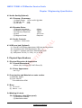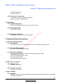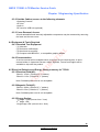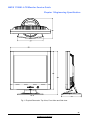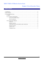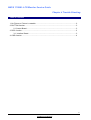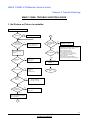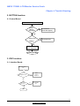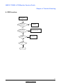
1
NMVS 1700M+ LCD Monitor Service Guide
Chapter 1 Engineering Specification
Table of Contents
1. Introduction......................................................................................................................4
2. Operational Specification.................................................................................................5
2.1 Environment ..........................................................................................................5
2.1.1 Temperature............................................................................................5
2.1.2 Humidity ..................................................................................................5
2.1.3 Altitude ....................................................................................................5
2.2 Transportation .......................................................................................................5
2.2.1 Vibration Test ..........................................................................................5
2.2.2 Drop Test (with packing, non-operating condition)...................................5
2.3 Packing Configuration............................................................................................6
2.3.1 Container Specification...........................................................................6
2.3.2 Carton Specification ................................................................................7
2.3.3 Pallet Specification ..................................................................................8
2.3.4 Container Carrying Capacity....................................................................8
2.4 Electrostatic Discharge Requirements ...................................................................10
2.5 Safety Requirements .............................................................................................10
2.6 EMI Requirements .................................................................................................11
2.7 Reliability ...............................................................................................................11
2.8 Mechanical Design for TCO 99: .............................................................................11
2.9 Environment Protection Design :............................................................................12
2.10 Acoustical Noise ..................................................................................................12
3. Input / Output Signal Specification...................................................................................12
3.1 Input Signal Requirements.....................................................................................12
3.1.1 Signal cable (Directly attached to unit) ....................................................12
3.1.2 Video signals: ..........................................................................................13
3.1.3 Sync signal: .............................................................................................13
3.2 Function.................................................................................................................13
3.2.1 Support timing .........................................................................................13
3.3 Number of display colors: ......................................................................................14
3.4 Adjustment function ...............................................................................................14
3.5 Display Power Management System (DPMS) ........................................................15
3.6 Plug & Play DDC1/2B Support..............................................................................15
3.7 Power Supply Requirements..................................................................................19
3.7.1 Input Power Requirements ......................................................................19
1
Confidence and Property
NMVS 1700M+ LCD Monitor Service Guide
Chapter 1 Engineering Specification
Table of Contents
3.7.2 Output Power Requirements ...................................................................20
3.7.3 AC Power Inlet ........................................................................................20
3.7.4 Input Power Cord ....................................................................................20
3.7.5 Power Management ................................................................................20
3.8 Panel optical Characteristics.................................................................................20
3.9 Panel Electrical Specifications ...............................................................................22
3.10 Defect, Scratch and Dust .....................................................................................22
4. Functional specification ...................................................................................................23
4.1 Display Quality.......................................................................................................23
4.1.1 Display Data Area (with full white pattern) ...............................................23
4.1.2 Video Performance..................................................................................23
4.1.3 Light Output.............................................................................................23
4.1.4 Brightness Adjustment Range .................................................................23
4.2 Audio Quality(Optional)..........................................................................................24
4.2.1 Preamp + Poweramp:..............................................................................24
4.2.2 Speaker Driver: .......................................................................................24
4.2.3 Audio Controls:........................................................................................24
4.3 USB pure hub (Optioal ...........................................................................................24
5. Physical Specifications ....................................................................................................24
5.1 Physical Dimension & Appearance ........................................................................24
5.1.1 Overall Dimensions: ................................................................................24
5.1.2 Outer Appearance: ..................................................................................24
5.2 Construction and Materials on outer surface..........................................................24
5.3 Base ......................................................................................................................24
5.4 Marking & Labels ...................................................................................................24
5.4.1 Reference Label (Rear panel) .................................................................24
5.4.2 Controls & Connectors ............................................................................25
5.5 Packaging..............................................................................................................25
5.5.1 Carton Dimension:...................................................................................25
5.5.2 Shipping Weight: .....................................................................................25
5.5.3 Shipping Container: .................................................................................25
6. Maintainability Specifications ...........................................................................................25
6.1 General & Requirements .......................................................................................25
6.1.1 Installation: ..............................................................................................25
2
Confidence and Property
NMVS 1700M+ LCD Monitor Service Guide
Chapter 1 Engineering Specification
Table of Contents
6.1.2 Periodic Maintenance: .............................................................................25
6.1.3 Repair & Calibration: ...............................................................................25
6.2 Mean Time to Repair .............................................................................................25
6.2.1 Module Level ...........................................................................................25
6.2.2 Component Level ....................................................................................25
6.3 Accessibility ...........................................................................................................25
6.3.1 General: ..................................................................................................25
6.3.2 Outside Cabinet, access to the following elements..................................26
6.3.3 Cover Removal, Access ..........................................................................26
6.4 Equipment & Tools Required .................................................................................26
6.4.1 Standard Test Equipment........................................................................26
6.4.2 Documentation ........................................................................................26
6.5 Electrical Emission and Energy Saving summary for TCO99.................................26
6.5.1 Electrical Field(AC):.................................................................................26
6.5.2 Magnetic Field(AC):.................................................................................26
6.5.3 Energy Saving: ........................................................................................26
3
Confidence and Property
NMVS 1700M+ LCD Monitor Service Guide
Chapter 1 Engineering Specification
1. Introduction
This specification describes a 17” analog color TFT LCD monitor. It can support maximum
resolution 1280x1024 at 75Hz refresh rate. There are the following features:
- User controls:
(a) “Power on/off” switch.
(b) “Exit” key (Back to main OSD menu or leave OSD menu).
(c) “I-key”(Intelligent key for automatic adjustment function by pressing this button).
(d) “Enter” key (for enter OSD sub-menu or select items).
(e) “Fly Wheel”(for selecting adjustable items in left/right direction and increasing /
decreasing the selected item by rotating it).
- OSD window for control and information display with 6 languages selection.
- DPMS (Display Power Management System)
- Power on/off indicator.
- High quality advanced zoom function (Scaling function)
- Swivel/Tilt base (with 300 degree swivel function and up/down tilt function from 0 to +25
degree).
- DDC1/2B function supported.
- Audio speakers supported.
- Optional USB hub supported (compliance with USB version 1.1)
It is composed of the following materials:
- A LCD monitor
(a) Head part:
(1) A LCD module (Samsung: LTM170E4-L01).
(2) An Inverter board.
(3) An AC-DC board(with audio circuit)
(4) An Interface board.
(5) A control board.
(6) An undetachable 15pin D-sub signal cable.
(7) Two speakers (optional).
(b) Base part:
- Swivel/Tilt base.
- A power cord.
- A user menu.
- Setup disk. (including .INF/.ICM/.CAT/Test pattern)
- A Macintosh signal adapter.
- An audio cable.
- An 1 upstream port/2 downstream ports USB hub(optional).
4
Confidence and Property
NMVS 1700M+ LCD Monitor Service Guide
Chapter 1 Engineering Specification
2. Operational Specification
2.1 Environment
2.1.1 Temperature
- Operating
5 to +35°C
- Non-operating
-20 to +60°C
2.1.2 Humidity
- Operating
- Non-operating
20% to 80% at non-condensing and less than 39°C condition
5% to 95% at non-condensing and less than 39°C condition
2.1.3 Altitude
0 to 3,657m (12,000ft)
0 to 12,192m (40,000ft)
- Operating (without packing condition)
- Non-operating (with packing condition)
2.2 Transportation
2.2.1 Vibration Test
2.2.1.1 Sinusoidal Vibration Test
Frequency (Hz): 2-200-2 Hz
Acceleration: 0.3 G
*Duration: 25 Minutes / Per Axis (X, Y, and Z Axis)
Acceleration: 0.5 G at resonant frequency
*Duration: 15 Minutes / Per Axis (X, Y, and Z Axis)
(Test passed criteria: After test, there is no electrical and mechanical damage.)
2.2.1.2 Random Vibration Test:
10 – 200 – 10Hz, 1.04Grms, 15 min, X, Y, Z Axis. Each one time.
Frequency (Hz)
G 2 /Hz (PSD Level)
2.0
0.0010
4.0
0.0300
8.0
0.0300
40.0
0.0030
55.0
0.0100
.70.0
0.0100
200.0
0.0010
(Test passed criteria: After test, there is no electrical and mechanical damage.)
2.2.2 Drop Test (with packing, non-operating condition)
2.2.2.1 Drop Height: 88 cm.
2.2.2.2 Drop Sequence
5
Confidence and Property
NMVS 1700M+ LCD Monitor Service Guide
Chapter 1 Engineering Specification
Surface number define:
6
2
1: Top
1
2: Front
3: Bottom
4
4: Rear
Manufacturing
joint
5: Left
5
3
6: Right
-Corner 5-3-2 select at weakness side [the low left(or right) corner of the front panel]
-An edge drop with impact on the shortest edge radiating from corner 5-3-2
-An edge drop with impact on the next shortest edge radiating from corner 5-3-2
-An edge drop with impact on the longest edge radiating from corner 5-3-2
-A flat drop with impact on the rear
-A flat drop with impact on the right
-A flat drop with impact on the left
-A flat drop with impact on the front
-A flat drop with impact on the bottom
-A flat drop with impact on the top
(Test passed criteria: After test, there is no electrical and mechanical damage.)
2.3 Packing Configuration
2.3.1 Container Specification
a. Shipping Container
Container Type
20'*8'*8'6" Steel 40'*8'*8'6" Steel
40'*8'*9'6"
High Cube Steel
Weight (Unit: Kg)
Interior Measurement (Unit:
mm)
Gross
24,000
30,480
30,480
Tare
2,370
4,000
4,200
Payload
21,630
26,480
26,280
Length
5,898
12,031
12,031
Width
2,352
2,352
2,352
6
Confidence and Property
NMVS 1700M+ LCD Monitor Service Guide
Chapter 1 Engineering Specification
Height
Volume(Cubic Meter)
2,394
2,394
2,699
33.2
67.74
76.4
Door opening
Width
2,340
2,340
2,340
(Unit: mm)
Height
2,280
2,280
2,585
Useable Interior Dimension
Length
5,890
12,000
12,000
Width
2,330
2,330
2,330
Height
2,120
2,120
2,405
(Deducted pallet(110mm &
Operating space 50mm))
Container (1)
Container (3)
125"*96"*96"
125"*96"*118"
125"*88"*64"
6,804
6,804
4,627
129
129
129
Payload
6,675
6,675
4,498
Length
3,048
3,048
3,048
Width
2,260
2,260
2,082
Height
2,438
2,997
1,625
17
19
11
(Unit: Kg)
Tare
Interior Measurement
(Unit: mm)
Gross
Weight
Container (2)
Container Type
b. Air Transport
Volume(Cubic Meter)
2.3.2 Carton Specification
Product
Weight(Kgs)
Net
Gross
5.5
7.6
Carton Interior
Measurement(mm)
Length
Width
Height
450
426
211
Carton External
Measurement(mm)
Length
Width
Height
482
446
231
7
Confidence and Property
NMVS 1700M+ LCD Monitor Service Guide
Chapter 1 Engineering Specification
2.3.3 Pallet Specification
A. Dimension
Transport Type
Pallet A
Pallet B
Pallet C
Length
676
X
X
Dimension
Width
1140
X
X
(Unit: mm)
Height
115
X
X
Air Transport Pallet
Length
676
676
X
Dimension
Width
1140
570
X
(Unit: mm)
Height
115
115
X
Shipping Pallet
2.3.4 Container Carrying Capacity
A. Shipping Container
Stowing Type
Quantity of pallet
(sets)
(Every Container)
20'
540
Pallet A: 6
Pallet B: 6
Pallet A: 36
Pallet B: 54
40'
1080
Pallet A: 12
Pallet B: 12
Pallet A: 36
Pallet B: 54
600
X
X
X
X
X
X
X
X
Quantity of
Quantity of
products (sets)
Products (sets)
(Every container) (Every Pallet)
With pallet
without pallet
20'
40'
1200
8
Confidence and Property
NMVS 1700M+ LCD Monitor Service Guide
Chapter 1 Engineering Specification
Container( 3 )
Container Type
C. Air Transport Container
B. Shipping container Stowing Method
3048 * 2082 * 1625
Quantity of
Quantity of
Quantity of pallet
products (sets)
Products (sets)
(sets)
(Every container)
(Every Pallet)
(Every Container)
60
Pallet A: 8
Pallet A: 6
Pallet B: 4
Pallet B: 3
Pallet C: X
Pallet C: X
9
Confidence and Property
NMVS 1700M+ LCD Monitor Service Guide
Chapter 1 Engineering Specification
D. Air Transport Container Stowing Method
2.4 Electrostatic Discharge Requirements
The subject product must withstand 4 KV for contact discharge and 8 KV for air
discharge of Electrostatic Discharge and meet the acceptance criteria as specified in
XXXISO 9241-3XXX -- should be IEC 801-2 .
2.5 Safety Requirements
The display unit complies with the following safety standards and specifications.
- UL compliance....standard for information-processing and business equipment,
UL 1950.
- CSA compliance...standard C22.2 No. 950-M89, data processing equipment.
- TUV compliance...EN60950 safety specification-business equipment.
- ISO13406-2 .Ergonomic Requirements of Visual Display.
- Nemko...EN60950
10
Confidence and Property
NMVS 1700M+ LCD Monitor Service Guide
Chapter 1 Engineering Specification
2.6 EMI Requirements
1. This display unit complies with the following EMC rules and regulations.
- FCC compliance...FCC Rule, Part 15, Subpart B, Class B.
- VCCI compliance...VCCI Rule, Class-2.
- CE Mark Compliance... 89/336/EEC.
EN55022 Class B
EN61000-3-2
EN61000-3-3
EN55024
EN61000-4-2, EN61000-4-3, EN61000-4-4, EN61000-4-5
EN61000-4-6, EN61000-4-8, EN61000-4-11
- DNSF compliance...EN55022, Class B.
- MPR2 compliance & EN50279
- TCO99(option)
2. The sample for EMI agency approval should be under 3 dB of the limit.
The production pilot run units should be under 3 dB of the limit.
The mass production units should be under 1 dB of the limit.
2.7 Reliability
1. The prediction MTBF of display unit shall be greater than 40,000 hours excluding the lamp.(at 25 ℃)
2. Lamp life time : 20,000 hrs minimum at which brightness of lamp is 50% compare to that of initial
value at Ta=25+/-2°C and IL=13.0mArms.
2.8 Mechanical Design for TCO 99:
1) Front Frame Reflectance:
* diffuse reflectance: > 20%
* Gloss <= 30% gloss unit
2) Labeling of plastics:
Plastic weight > 25g shall be marked in accordance with ISO11469
3) Variety of Plastic:
All plastic components that weight > 100g shall be made from the same type of plastic.
4) Painting of Plastic:
* Any plastic components that weight >100g shall not be painted lacquer or vanished, so that
the paint, lacquer or vanish in dry matter exceed 1 weight-% of the plastic component.
* Mould decoration (IMD) is not allowed
* All paints, lacquers, vanishes or colour additives used shall be declared by the type and
mount.
5) Metallization of Plastic Housing:
* Metallization is not allowed.
11
Confidence and Property
NMVS 1700M+ LCD Monitor Service Guide
Chapter 1 Engineering Specification
6) Plastic components > 25g shall not contain retardants of organically bound chloride or
bromide.
2.9 Environment Protection Design :
Product is Per ES 715-c49 Environment Design Guide
2.10 Acoustical Noise
With the display operating, the issue of sound measured is contained within 40 dB/A in the audible
3. Input / Output Signal Specification
field.
3.1 Input Signal Requirements
3.1.1 Signal cable (Directly attached to unit)
3.1.1.1 Video Inputs:
15pin D-sub connector is on the captive signal cable for IBM VGA, compatible graphic
adapters. The pin assignment of this connector is described as below:
5
1
6
11
10
15
15-pin D-sub female
1 RED VIDEO
2 GREEN VIDEO
3 BLUE VIDEO
4 GROUND
5 GROUND
6 RED GROUND
7 GREEN GROUND
8 BLUE GROUND
9 PC5V
10 SYNC GROUND
11 GROUND
12 SDA
13 H SYNC (H+V)
14 V SYNC
15 SCL
3.1.1.2 Cable length:
1500mm +/- 20mm
12
Confidence and Property
NMVS 1700M+ LCD Monitor Service Guide
Chapter 1 Engineering Specification
3.1.2 Video signals:
RGB separate, Analog 0.7Vp-p/75 Ohm
3.1.3 Sync signal:
- H/V separate , TTL level
- H/V composite ,TTL level
3.2 Function
3.2.1 Support timing
This Interface board is designed to operate in any of the following video mode.
Incoming display mode(Input timing)
Vertical
Dot Clock
Remark
Frequency (KHz)
Frequency (Hz)
Frequency (MHz)
640x350
31.47(P)
70.08(N)
25.17
*720x400
31.47(N)
70.08(P)
640x480
31.47(N)
60.00(N)
640x480
35.00(N)
67.00(N)
640x480
37.86(N)
72.80(N)
640x480
37.50(N)
800x600
full screen
28.32
DOS
1280x1024
25.18
DOS
DOS
Macintosh
31.5
VESA
75.00(N)
31.5
VESA
37.88(P)
60.32(P)
40.00
VESA
800x600
48.08(P)
72.19(P)
50.00
VESA
*800x600
46.86(P)
75.00(P)
49.50
VESA
832X624
49.72(N)
74.55(N)
57.29
Macintosh
*1024x768
48.36(N)
60.00(N)
65.00
VESA
1024x768
56.48(N)
70.10(N)
75.00
VESA
*1024x768
60.02(P)
75.00(P)
78.75
VESA
1024X768
60.24(N)
74.93(N)
80.00
Macintosh
1152x864
67.50(P)
75.00(P)
108.00
VESA
*1152x870
68.68(N)
75.06(N)
100.00
Macintoch
1152x900
61.80(N)
66.00(N)
94.50
SUN 66
1152x900
71.81(N)
76.14(N)
108.00
SUN
*1280x1024
64.00(P)
60.00(P)
108.00
VESA
1280x1024
75.83(N)
71.53(N)
128.00
IBM1
*1280x1024
80.00(P)
75.00(P)
135.00
VESA
*1280x1024
81.18(N)
76.16(N)
135.09
SPARC2
*1280x960
60.00(P)
60.00(P)
108.00
VESA
*1280x960
75.00(P)
75.00(P)
129.60
VESA
30.24
Actual display
resolution
Horizontal
Resolution
Multi-scan operation
1280x960
13
Confidence and Property
NMVS 1700M+ LCD Monitor Service Guide
Chapter 1 Engineering Specification
Notes (1) The timings with “*”symbol will be adjusted in the factory.
(2) If the incoming display mode is not supported by this I/F board listed above, the up side
of OSD window will show “Non Preset Mode” as below to indicate it. Maybe the picture
can show up or doesn’t which is unpredictable, even the picture can display but probably
isn’t good or clear.
etc
Non Preset Mode
Luminance
Enter : Select
Exit : Exit
No Signal
(3) Some signals from graphics board may not function properly.
(4) “P”, “N” stands for “Positive”, “Negative” polarity of incoming HSYNC/VSYNC(input
timing).
(5) OSD will show “No Signal” message on the screen as below to indicate it while no
display mode inputs,
(6) OSD will show “Out of Range” message on the screen as below to indicate it while input
display mode meet the following condition,
(a)The resolution is larger than 1280x1024.
(b)The resolution is 1280x1024 but its frequency of vertical sync(Fv) is larger than 77Hz.
(c)The frequency of horizontal sync(Fh) is larger than 90KHz.
(d)The frequency of vertical sync(Fv) is larger than 110Hz.
Out of Range
3.3 Number of display colors:
16M color numbers
3.4 Adjustment function
(A) Hot key function: Contrast, Brightness & Speaker Volume(optional) adjustment.
(B) Main OSD menu:
1.) Luminance: Contrast and Brightness adjustment.
2.) Geometry: Horizontal Position, Vertical Position, Phase and Pixel Clock adjustment.
3.) Color Adjustment: Recall preset R,G,B color, Red, Green and Blue adjustment.
4.) Input signal information: Recall preset geometric values.
5.) Miscellaneous: OSD Position adjustment, Zoom(on/off) and Language Selection.
14
Confidence and Property
NMVS 1700M+ LCD Monitor Service Guide
Chapter 1 Engineering Specification
3.5 Display Power Management System (DPMS)
This Interface board will automatically cut down the power of the monitor when not receiving
HSYNC or VSYNC signals over about 5 seconds, and the condition are as below,
HSYNC
Pulse
no pulse
Pulse
no pulse
VSYNC
pulse
pulse
no pulse
no pulse
LCD Module
on
off
off
off
Backlight
on
off
off
off
3.6 Plug & Play DDC1/2B Support
When the DDC function is supported, it is necessary to input all EDID data(128 bytes) by
using SCL and SDA signal, the DDC data table is as below:
Data
Description
00
00
01
FF
02
FF
03
FF
04
FF
05
FF
06
FF
07
00
08
38
09
A3
0A
B5
0B
65
(Vender Assigned code)
0C
01
Not used
0D
01
0E
01
0F
01
10
*
Week of Manufacture (0-53),use 0 if n/a
11
*
Year of Manufacture (year – 1990)
12
01
EDID version
13
03
Revision
14
6C
Video Input Define
15
22
Max. H. Image Size (cm) = 33.79 cm
16
1B
Max. V. Image Size (cm) = 27.03 cm
17
78
(gamma*100) – 100
Address
Header
ID Manufacturer Name = NEC
ID Product Code = LCD1700M+
15
Confidence and Property
NMVS 1700M+ LCD Monitor Service Guide
Chapter 1 Engineering Specification
Data
Description
EA
DPMS
19
6E
Red Green Bits Rx1Rx0Ry1Ry0Gx1Gx0Gy1Gy0
1A
87
Blue White Bits Bx1Bx0By1By0Wx1Wx0Wy1Wy0
1B
A2
Red x bit9-2 (Red_x = 0.634)
1C
5A
Red y bit9-2 (Red_y = 0.354)
1D
4D
Green x bit9-2 (Green _x = 0.304)
1E
94
Green y bits9-2 (Green_y = 0.581)
1F
24
Blue x bit9-2 (Blue_x = 0.143)
20
1A
Blue y bit9-2 (Blue_y = 0.102)
21
51
White x bit9-2 (White _x = 0.318)
22
56
White y bit9-2 (White_y = 0.339)
23
BD
Established Timing I
24
EF
Established Timing II
25
80
Established Timing III
26
71
Standard Timing Identification
27
4F
#1
28
81
#2
29
80
2A
81
#3
2B
8C
2C
81
2D
90
2E
81
2F
40
30
01
31
01
32
01
33
01
34
01
35
01
18
Address
1152X864 75HZ
1280X1024 60HZ
#4
#5
#6
#7
#8
Detailed Timing Description # 1 = 1280 X 1024 @ 60HZ
36
30
LSB value of “Pixel clock/10,000” (Pixel clock=108MHz)
37
2A
38
00
MSB value of “Pixel clock/10,000” (Pixel clock=108MHz)
Horizontal Active(Pixels, lower 8 bits) = 1280(D) = 0500(H)
39
98
Horizontal Blanking(Pixels, lower 8 bits) = 408(D) = 0198(H)
16
Confidence and Property
NMVS 1700M+ LCD Monitor Service Guide
Chapter 1 Engineering Specification
3A
51
Description
Horizontal Active(upper 4 bits): Horizontal Blanking(upper 4 bits)
3B
00
Vertical Active(Lines, lower 8 bits) = = 1024(D) = 0400(H)
3C
2A
3D
40
Vertical Blanking(Lines, lower 8 bits) == 42(D) = 002A(H)
Vertical Active(upper 4 bits): Vertical Blanking(upper 4 bits)
3E
30
H.Sync. Offset(Pixels, H. Front Porch, lower 8 bits)==48(D)=0030(H)
3F
70
Horizontal Sync Pulse Width(Pixels, lower 8 bits)==112(D)=0070(H)
40
13
41
00
42
52
V. Sync Offset(bit 3,2), C. Sync Pulse Width(bit 1,0)
Horizontal Image Size(mm, lower 8 bits) = = 359(D) = 167(H)
43
0E
Vertical Image Size(mm, lower 8 bits) == 287(D) = 11F(H)
44
11
45
00
Horizontal Border(Pixels) = 0
46
00
Vertical Border(Lines) = 0
47
1E
Non-interlaced, no stereo, Digital separate, H,V-Polarity=(+,+)
48
00
Flag=00h when block used as descriptor
49
00
4A
00
Flag=00h when block used as descriptor
Reserved when block(address 48~59) is defined as descriptor
4B
FD
4C
00
4D
38
4E
4B
Min. Vertical rate(Hz) = 56(Hz)
Max. Vertical rate(Hz) = 75(Hz)
4F
1F
Min. Horizontal rate(kHz) = 31(kHz)
50
51
Max. Horizontal rate(kHz) = 81(kHz)
51
0E
Max. Supported Pixel Clock(MHz) = 140(MHz)
52
0A
No secondary timing formula supported
53
20
(unused)
54
20
(unused)
55
20
(unused)
56
20
(unused)
57
20
(unused)
58
20
(unused)
59
20
(unused)
Vertical Sync Offset(upper 4 bits):Vertical Sync Pulse Width(upper 4
bits)
H. Sync Offset(bit 7,6), H. Sync Pulse Width(bit 5,4),
Horizontal Image Size(upper 4 bits) & Vertical Image Size(upper 4
bits)
Data
Set this block as “Monitor Range Limits” descriptor
Flag=00h when block used as descriptor
Address
17
Confidence and Property
NMVS 1700M+ LCD Monitor Service Guide
Chapter 1 Engineering Specification
Address
Data
Description
00
Flag=00h when block used as descriptor
5B
00
Flag=00h when block used as descriptor
5C
00
Reserved when block(address 5A~6B) is defined as descriptor
5D
FC
Set this block as “Monitor Name” descriptor
5E
00
5F
4E
Flag=00h when block used as descriptor
1st character =N
60
45
61
43
2nd character = E
3rd character = C
62
20
4th character = <space>
63
4C
5th character = L
64
43
6th character = C
65
44
7th character = D
66
31
8th character = 1
67
37
9th character = 7
68
30
10th character = 0
69
30
11th character = 0
6A
4D
12th character = M
6B
2B
13th character = +
6C
00
Flag=00h when block used as descriptor
6D
00
6E
00
Flag=00h when block used as descriptor
Reserved when block(address 6C~7D) is defined as descriptor
6F
FF
70
00
Set this block as “Monitor Serial Number” descriptor
Flag=00h when block used as descriptor
71
*
(Varies)
72
*
(Varies)
73
*
(Varies)
74
*
(Varies)
75
*
(Varies)
76
*
(Varies)
77
*
(Varies)
78
*
(Varies)
79
*
(Varies)
7A
0A
(unused)
7B
20
(unused)
7C
20
(unused)
5A
18
Confidence and Property
NMVS 1700M+ LCD Monitor Service Guide
Chapter 1 Engineering Specification
Address
Data
Description
7D
20
(unused)
7E
00
Extension Flag
7F
*
Check sum
3.7 Power Supply Requirements
3.7.1 Input Power Requirements
(1) Input Voltage Range
The unit shall meet all the operating requirements with an input voltage range of
90~264 Vac .
(2) Input Current
Maximum
Input Current
Measuring Range
(MAX) 2 Arms
90Vac 〜 264Vac
(3) Frequency Range
The unit shall operate within a frequency range of 47Hz to 63Hz.
(4) Inrush Current
Power supply inrush current shall be less than the ratings of its critical components
(including Power switch, fuse, rectifiers and surge limiting device) for all conditions of
line voltage.
(5) Regulator Efficiency
70% minimum (measuring at 115Vac and full load)
(6) Power line Transient Immunity
The power supply shall function properly after being subjected to a 8us/20us, 2000
volts (gnd to line), 1.2us/50us(line to line) or 5ns/50ns,1000 volts fast peak pulse
applied either differentially or single end to line and neutral at any phase of the
power line voltage and shall not cause an unsafe or unrecoverable errors.
(7) Maximum power consumption <45 Watts (without USB hub & without audio).
Maximum power consumption <54 Watts (without USB hub & with audio).
Maximum power consumption < 53 Watts (with USB hub & without audio)
Maximum power consumption < 62 Watts (with USB hub & with audio)
Power saving mode < 3 Watts (without USB hub)
(8) Safety concern: 1. Earth leakage current < 3.5mA at 264Vac( < 0.5mA at 100VAC )
2. Electric strength<10mA
3. Primary-Secondary: 4242(DC).
4. Primary-Earth: 2121(DC)
19
Confidence and Property
NMVS 1700M+ LCD Monitor Service Guide
Chapter 1 Engineering Specification
3.7.2 Output Power Requirements
The power circuit shall supply DC power outputs as followings:
Output
Nominal
Regulation
Load Current Range
1
12V
±10%
0 ~ 3.0A
2
5V-Fix
±3%
0 ~ 1.2A
3
5V
±3%
0 ~ 500mA
4
3.3V
±3%
0 ~ 1A
3.7.3 AC Power Inlet
The display unit shall be supplied with an AC power INALWAYS 0174(or
equivalent), to be located at the rear of the LCD Monitor.
3.7.4 Input Power Cord
Each AC adapter unit shall be supplied with a input power cord, with length of 1800mm
king cord KC-003 or equivalent.
3.7.5 Power Management
H/Vsync
Power consumption
Normal
Both exist
off
None or
only one exist
< 45W
(without USB hub)
< 3W
(without USB hub)
LED Color
(Status)
Green
(Normal)
Amber
Mode
Recovery
Time
-3 sec
3.8 Panel optical Characteristics
SAMSUNG LT170E2-132 optical characteristics are determined after the unit has been ‘ON’
and stable for approximately 30 minutes in a dark environment at 25℃. The values specified
are at an approximate distance 50cm from the LCD surface at a viewing angle of Φ and θ equal
to 0° and aperture 1 degree. The test equipment is BM-7. The input signal voltage and timing
specification are VDD of 5V, 60Hz of Fv and 54MHz of pixel rate respectively. The input current
of backlight is 13mArms.
Parameter
CR
Contrast Ratio
Luminance of White(center of screen)
Brightness Uniformity
Response Time
Symbol
Rise Time
Decay Time
CIE Color Coordinates
Red
Green
Blue
Min.
Values
Typ.
Max.
250
350
-
Units
Notes
1
2
YL
170
200
-
cd/m
Buni
-
-
25
%
Tr
TR
TF
-
35
20
15
40
20
20
msec
xR
yR
xG
yG
xB
yB
0.604
0.324
0.274
0.551
0.113
0.078
0.634
0.354
0.304
0.581
0.143
0.102
0.664
0.384
0.334
0.611
0.173
0.132
2
3
20
Confidence and Property
NMVS 1700M+ LCD Monitor Service Guide
Chapter 1 Engineering Specification
White
Viewing Angle by CR ≥ 10
x axis, right (Φ=0º)
x axis, left(Φ=180º)
y axis, up(Φ=90º)
y axis, down (Φ=270º)
xW
yW
0.288
0.309
0.318
0.339
0.348
0.369
θ
θ
θ
θ
70
70
70
70
80
80
80
80
-
degree,
°
4
OPTICAL CHARACTERISTICS
Notes 1. Contrast Ratio (CR) is defined mathematically as:
(Surface Brightness with all white pixels)
(Surface Brightness with all black pixels)
Contrast ratio shall be measured at the center of the screen (Location 5).
2. Luminance of White is brightness value at location 5(refer to note 3) at center of
the screen.
128
3. The 9 points brightness uniformity, Buni is defined as :
)|
|Maximum (B1, B2, ....B9) - Minimum (B1, B2, ....B
× 9100(%)
Maximum (B1, B2, .... B9)
Where B1 to B9 are the brightness with all pixels displaying white at 9 locations.
1152
8
7
102
4
512
1
922
9
5
6
(pixel)
640
3
2
4. Viewing angle is the angle at which the contrast ratio is greater than 10.
Normal Line
φ = 0o
θ
θ=0
o
L
θ
θ
L
6 o'clock
direction
φ L= 90 o
=90
o
x
φ
L
φ
R
H
12 o'clock
direction
φ H = 90 o
y
y'
x'
θ R =90 o
21
Confidence and Property
NMVS 1700M+ LCD Monitor Service Guide
Chapter 1 Engineering Specification
3.9 Panel Electrical Specifications
The SAMSUNG LTM170E4-L01 requires two power inputs. One input is employed to power
the LCD electronics and to drive the voltages to drive the TFT array and liquid crystal. And the
second input for the backlight CCFL, is typically generated by an inverter. The inverter is an
external unit to the LCD.
Table 2 ELECTRICAL CHARACTERISTICS:
SYMBOL MIN
TYP
MAX
UNIT
Lamp Current
IL
2.0
6.5
7.0
mArms
Lamp Voltage
VL
-
690
-
Vrms
Lamp
Frequency
Operating
Time
fL
30
-
80
KHz
-
-
-
-
1100(25°C)
1420(0°C)
NOTE
1
Hour
2
Vrms
3
Startup Voltage Vs
20,000
Life Hr
ITEM
Notes: 1. Lamp frequency may produce interference with horizontal synchronous frequency
and this may cause line flow on the display. Therefore lamp frequency shall be
detached from the horizontal synchronous frequency and its harmonics as far
as possible in order to avoid interference.
2. Life time (Hr) of a lamp is defined as the time in which it continues to operate under the
0
condition of Ta = 25 ± 2 C and IL = 6.5mArms for one lamp until the brightness
becomes 50% or lower than it’s original value.
3. If an inverter has shutdown function it should keep its output for more than 1 second
even if the lamp connector open. Otherwise the lamps may not to be turned on.
3.10 Defect, Scratch and Dust
Defect Type
Accept
Reject
N <= 6
N> 6
Bright dot
Random
Green >2
Two adjacent (Horizontal)
(Vertical)
Three adjacent
N <= 1
N>1
N <= 1
N>1
Not allowed
Not allowed
N <= 6
N> 6
N <= 2
N>2
Four or more adjacent
Dark dot,
Random
Two adjacent (Horizontal)
(Vertical)
22
Confidence and Property
NMVS 1700M+ LCD Monitor Service Guide
N <= 1
N>1
N <= 0
N> 0
Not allowed
Not allowed
N <=6
N>6
Bright dot –to-bright dot
L => 15 mm
L< 15 mm
Dark dot – to – dark dot
L=> 5mm
L < 5mm
R.G.B, Black, white
D<= 0.8 mm
D>0.8 mm
Gray pattern (128 gray)
D<= 0.5 mm
Chapter 1 Engineering Specification
Three adjacent (Horizontal)
Three adjacent (Vertical)
Maximum allowable number
of dot defect
Minimum distance between
defects,
D>0.5 mm
4. Functional specification
White spot
All the tests to verify specifications in this section must be performed under the following
standard conditions unless otherwise noted. The standard conditions are:
- Temperature: 5 to 35 degree Celsius
- AC line input voltage: 100 Vac to 240 Vac, 50Hz or 60Hz
- Warm-up time: 30 minutes minimum
4.1 Display Quality
4.1.1 Display Data Area (with full white pattern)
(1) Horizontal: 337.9 +/- 0.5 mm
(2) Vertical: 270.3 +/- 0.5 mm
4.1.2 Video Performance
(1) Resolution: 1280 X 1024 pixels Maximum
(2) Contrast ratio: 250(Min.)
(3) Response time: 35 mS (Typ.)
(4)Viewing angle : U/D:70° R/L:70° (Min.) (At contrast ratio >= 10)
(5)CIE Coordinate: White (0.318, 0.339) +/- (0.03, 0.03)
(6) Display color: 16.7M
4.1.3 Light Output
Brightness rating : 200cd/㎡ (Typ.) (usre mode color temp.)
4.1.4 Brightness Adjustment Range
At contrast ratio control set at maximum level, adjusting Brightness control from
minimum to maximum position, the light output of WHITE pattern shall be increased
more than 40cd/㎡.
23
Confidence and Property
NMVS 1700M+ LCD Monitor Service Guide
Chapter 1 Engineering Specification
4.2 Audio Quality(Optional)
4.2.1 Preamp + Poweramp:
(1) Output Power:
(2) THD (@ 1W):
(3) S/N ratio:
1.0 W rms/CH @ 1KHz
<1%
50db
4.2.2 Speaker Driver:
(1) Nominal Impedance:
(2) Maximum Input Power:
(3) Frequency Response:
(4) Size:
(5) Magnetic Shield:
8 Ohm
2W/CH
12KHz
30*70 mm
Required
4.2.3 Audio Controls:
(1)Volume 0-99 Levels
4.3 USB pure hub (Optional)
Use ISP1122 (Philips stand-alone USB hub device) solution.
Compliance with “USB Specification Rev. 1.1:.
Support 1 upstream port and 2 downstream ports.
USB power: DC 5V (+/- 0.5V), 1A (+/- 0.1A)
5. Physical Specifications
(1)
(2)
(3)
(4)
5.1 Physical Dimension & Appearance
5.1.1 Overall Dimensions:
422mm (W) X 451mm (H) X 207.97mm (D)
5.1.2 Outer Appearance:
see Fig.1
5.2 Construction and Materials on outer surface
(1) Materials: Plastic
(2) Color: WHITE
To be defined for OEM
5.3 Base
(1) Tilt: 0/+25 °
(2) Swivel: ± 150°
5.4 Marking & Labels
5.4.1 Reference Label (Rear panel)
(1) Reference numbers
(2) Manufacture data
24
Confidence and Property
NMVS 1700M+ LCD Monitor Service Guide
Chapter 1 Engineering Specification
(3) Agency Approvals
(4) Power Ratings
5.4.2 Controls & Connectors
(1) AC power cord input: abbreviated labels
(2) User's Controls: standard print
5.5 Packaging
5.5.1 Carton Dimension:
570mm (W) X338mm (D) X 621mm (H) (LCD monitor)
5.5.2 Shipping Weight:
10kg (LCD monitor)
5.5.3 Shipping Container:
6.1 General & Requirements
6.1.1 Installation:
6. Maintainability Specifications
420 sets per 40 feet container without pallet.
From outside of unit with standard tools and documentation provided to user.
6.1.2 Periodic Maintenance:
No periodic maintenance is required.
6.1.3 Repair & Calibration:
Require spare modules or components as specified as followings:
(1) Interface board ASSY
(2) AC-DC converter board ASSY
(3) Control board ASSY
(4) USB board ASSY (optional)
6.2 Mean Time to Repair
6.2.1 Module Level
Less than 10 minutes
6.2.2 Component Level
Less than 15 minutes
6.3 Accessibility
6.3.1 General:
All panels, covers, and major assemblies are removable without disruption of permanent
mounting or fasteners.
25
Confidence and Property
NMVS 1700M+ LCD Monitor Service Guide
Chapter 1 Engineering Specification
6.3.2 Outside Cabinet, access to the following elements
-Operating Controls
-AC Inlet
-Audio in
-DC Jack for USB hub (optional)
6.3.3 Cover Removal, Access
All sub assemblies and internally adjustable components may be accessed by removing
the base and the rear cover.
6.4 Equipment & Tools Required
6.4.1 Standard Test Equipment
(1) Voltmeter
(2) Dual trace oscilloscope
(3) Hand tools as required
(4) Computer with IBM VGA , or compatible graphic adapter
6.4.2 Documentation
A service manual will be available which covers all service requirements. A users
manual written in Japanese German, Italian, Spanish, France and English will be
available to ship with the product.
6.5 Electrical Emission and Energy Saving summary for TCO99
6.5.1 Electrical Field(AC):
*Band I< 10V/m (132cd/m^2,”+” pattern)
*Band II< 1V/m (132cd/m^2,”+” pattern)
Note: Shielded power cord is not acceptable
6.5.2 Magnetic Field(AC):
*Band I< 200nt (132cd/m^2,”+” pattern)
*Band II< 32nt (132cd/m^2,”+” pattern)
Note: Shielded power cord is not acceptable
6.5.3 Energy Saving:
st
*1 stage: <15W (recover time: 3 sec)
nd
2 stage: <5W
*single stage:<5W (recover time: 3sec)
26
Confidence and Property
NMVS 1700M+ LCD Monitor Service Guide
Chapter 1 Engineering Specification
Fig. 1 Physical Dimension Top View, Front View and Side view
27
Confidence and Property
NMVS 1700M+ LCD Monitor Service Guide
Chapter 2 Circuit Operation Theory
Table of Contents
1. Introduction......................................................................................................................2
2. Block diagram..................................................................................................................2
3. Circuit operation theory ...................................................................................................3
A. HEAD ......................................................................................................................3
A-1.) Interface board diagram......................................................................................3
(a) Circuit operation theory: ..............................................................................3
(b) IC introduction:............................................................................................3
A-2.) AC-DC board diagram: .......................................................................................4
EMI Filter..........................................................................................................5
Rectifier and filter .............................................................................................5
Switching element and Isolation power transformer .........................................6
Rectifier and filter .............................................................................................6
Control circuit ...................................................................................................7
Feedback circuit ...............................................................................................7
1
Confidence and Property
NMVS 1700M+ LCD Monitor Service Guide
Chapter 2 Circuit Operation Theory
1. Introduction
The 1700M+ is a 17" SXGA (1280x1024) 24 bits color TFT LCD monitor with multi-media
function and an optional USB hub. It’s an analog interface LCD monitor with an nondetachable 15 pins D-sub signal cable and it’s compliant with VESA specification to offer a
smart power management and power saving function. It also offers OSD menu for users to
control the adjustable items and get some information about this monitor, and the best
function is to offer users an easy method to set all adjustable items well just by pressing one
key, we called it “Auto-key” (intelligent key) which can auto adjusting all controlled items.
2. Block diagram
The 1700M+ consists of a head and a stand (base). The head consists of a LCD module with 4
lamps, an Inverter, an interface board, a AC-DC board, a control board and two speakers.
The stand consists of an optional USB hub. The block diagram is shown as below.
HEAD
L C D m o d u le w it h 4 la m p s ( b a c k lig h t )
In v e r te r
A C -D C
b oard
In te r fa c e
b oard
C o n tro l b o a r d
S TA N D
(B a s e )
S p eak ers
U S B o p t io n a l h u b
A C in p u t
S ig n a l c a b le
( 1 5 p in D - s u b )
2
Confidence and Property
NMVS 1700M+ LCD Monitor Service Guide
Chapter 2 Circuit Operation Theory
3. Circuit operation theory
A. HEAD
A-1.) Interface board diagram
Interface Board
SDRAM
24bits RGB
(Odd/Even)
A/D
converter
Red
Green
Blue
Pixel clock Scaling IC
LVDS
Xmter
X2
To
LCD
module
Hsync
Vsync
Vsync
EEPROM
Hsync
(/H+V)
OSD IC
DDC IC
SCL
SDA
MCU
(a) Circuit operation theory:
A basic operation theory for this interface board is to convert analog signals of Red, Green
and Blue to digital signals of Red, Green and Blue, and by the internal PLL circuit of A/D
converter to generate the pixel clock to output to the scaling IC, then the scaling IC use the
SDRAM to be the frame buffer to process the different input signals which are operating in the
specification of the A/D converter and the scaling IC, finally the scaling IC output the digital
RGB data, the fixed frequency of Hsync, Vsync and pixel clock to LCD panel driver IC by
LVDS transmitter.
(b) IC introduction:
1.) DDC(Display Data Channel) IC: We use ATMEL 24C21 to support DDC1/2B function, it
will store the information related to LCD monitor and PC can read them by “Vsync and
SDA” serial communication for DDC1 or I² C communication for DDC2B.
3
Confidence and Property
NMVS 1700M+ LCD Monitor Service Guide
Chapter 2 Circuit Operation Theory
2.) A/D converter: We use AD9884 of ADI which can support maximum 140MHz pixel rate to
convert analog signals of RGB to 24bits digital RGB signals and generate a pixel clock
signal by Hsync and its internal PLL circuit, then transmit these digital signals to Scaling IC.
3.) Scaling IC: We use MX88L282 of Macronix and by its frame buffer function to process the
digital RGB signals to maximum 75Hz refresh rate at 1280 by 1024 resolution (about
135MHz pixel rate), it also support a ratio expansion function to display a full screen when
the resolution of input signals are less than 1280 by 1024.
4.) SDRAM: We use 3 pieces of 2M bytes SDRAM to be the frame buffer of the scaling IC to
process maximum 1280 by 1024 resolution of 24 bits RGB data.
5.) MCU: We use Myson MTV112V to controls all the functions of this interface board, just like
the mode detecting, OSD display setting, the adjustable items, adjusted data storage,
DPMS control, the external RS232 communication and the scaling IC.
6.) EEPROM: We use 24C04 to store all the adjustable data, and we divide it into two parts
for the storage of factory settings and user settings.
7.) OSD IC: We use LSC3852 of Motorolla to do “On Screen Display” function.
8.) LVDS transmitter IC: We use two THC63LVDM83A LVDS transmitter of THine to transmit
the digital data from the interface board to the LCD panel’s driver IC, which has a built-in
LVDS receiver IC.
A-2.) AC-DC board diagram:
Switching
Element
AC Input
( 90--264)
EMI Filter
Isolation
Power
Transformer
Rectifier
and
Filter
+12V(INV.)
Rectifier
and
Filter
Rectifier
and
Filter
Feedback
Isolation and
Control Logic
+5V-Fix
USB(+5V)
Fig. 1
4
Confidence and Property
NMVS 1700M+ LCD Monitor Service Guide
Chapter 2 Circuit Operation Theory
EMI Filter
This circuit (fig. 2) is designed to inhibit electric and magnetic interference for Meet FCC, VDE,
VCCI standard requirements.
L604
92U
C603
2200P
250V
(Y1)
C604
2200P
250V
(Y1)
C602
.1U
275v
(X)
L605
C601
.1U
275v
(X)
92U
1
3
2
4
L603
UU-15
R601
1M
1/2W
F601
T2AH
250V
Fig. 2
Rectifier and filter
AC Voltage (90-264V) is rectified and filtered by BD601, C605 (See Fig 3) and the DC Output
voltage is 1.4*(AC input). (See Fig.3)
BD601
2KPB06M
3
TR601
SCK083
~
4
1
-
+
~
C605
100U
400V
105C
+
2
Fig. 3
5
Confidence and Property
NMVS 1700M+ LCD Monitor Service Guide
Chapter 2 Circuit Operation Theory
Switching element and Isolation power transformer
When the Q601 turns on, energy is stored in the transformer. During Q601 OFF period, the
stored energy is delivered to the secondary of transformer. R604, C606 and D601 is a
snubber circuit. R605 is current sense resistor to control output power. (See Fig.4)
T601
4
C606
3300P
1KV
(D)
R604
68K
2W
PQ2625
3
5
6
D601
RGP10J
2
7
D602
RGP10D
Q601
K2645
R613
1K
R615
.22
2W
R614
20K
Fig. 4
Rectifier and filter
D701 and C701 are to produce DC output. L701 and C702 are to suppress high Frequency
switching spikes. R702 is a dummy load. (See Fig.5)
C702
2200P
500V
(D)
C701
2200P
500V
(D)
R701
22
1W
L701
3U
3
2
1
D701
+
C701
1000U
16V
105C
+
C702
1000U
16V
105C
R702
1/4W
330
Fig. 5
6
Confidence and Property
NMVS 1700M+ LCD Monitor Service Guide
Chapter 2 Circuit Operation Theory
Control circuit
The current mode control IC UC3843A is used to control PWM. When the VCC terminal of it
gets 8.4V, IC601 turns on. +5V will be set up at Pin8 through soft start circuit includes R617,
C611, D606 and D605. R616 and C610 generate a fixed frequency sawtooth wave at Pin4.
D602
1N4148
+C606
8
R616
22K
R617 D606
100K 1N4148
C612
0.1U
50V
(D)
D605
1N4148
+ C611
10U
25V
(EL)
R612
47
100U
25V
(EL)
6
7
VCC OUT
3
VREF IC601 ISSEN
UC3843A
4 R/C
GND
COMP FB
C610
1
2
5
1000P
C609
0.022U
100V
50V
(PE)
R618 (D)
10K
B
R613
1K
C608
2200P
50V
(D)
C
Fig. 6
Feedback circuit
TLP721F is a optocoupler and TL431 is a shunt regulation. They are used to detect the output
voltage change and primany and secondary isolation. When output voltage changes, the
feedback voltage will be compared and duty cycle will be decided to control the correct output
voltage. (See Fig.7)
5V-Fix
IC602
TLP721F
4
1
R712
560
1/4W
R619
1k
3
R712
10.2K
(1%)
2
C712
0.1U
50V
(D)
K
R
R622
1K
A
IC702
TL431
R714
10K
(1%)
Fig. 7
7
Confidence and Property
NMVS 1700M+ LCD Monitor Service Guide
Chapter 2 Circuit Operation Theory
Connect with
PC Audio output
Connect with
8 ohm/2W
Speaker
DC POWER
INPUT
AUDIO
INPUT
POWER IC
TDA7496
The Audio Speaker is consinst of a Audio board. The Audio Speaker have DC
Volumn control, use 28mmX40mm Speaker (2W/per chennal),power supply from ACDC board and Audio input from PC Audio output (Line Out) .
(A) Power IC: Use ST POWER IC TDA7496. The IC are stereo AB Class output
amplifiers with DC Volume control. The devices are designed for use in TV and
monitor, but are also suitable for battery-Fed portable recorders and radios. Use
+12V from AC-DC Board and connect speaker to offer 1W per chennal.
(B) DC Power Input:To supply +12V to be VCC source Voltage for TDA7496 and
built-in AC-DC board.
(C) Audio Input:connect with PC Audio output in 3.5mm to 3.5mm signal line.
(D) Speaker: Use 8 ohm and 28mmX40mm speaker (2W/per chennal)
(E) DC Volumn Control: The voltage range is 1 – 5 V (From MC)
8
Confidence and Property
NMVS 1700M+ LCD Monitor Service Guide
Chapter 3 Alignment Procedure
Alignment procedure (for function adjustment)
1. Enter factory area (press “enter” & “exit” then “power on”).
2. Select timing from figure 1. The timing marked with star sign (*) have to be adjusted.
Clear user area in EEPROM.
3. Adjust the contrast and the brightness to “50”.
4. Press I-key to adjust the image.
5. Check the phase of the image; if phase is not perfect adjust it to the best step.
6. Save factory parameter then turn off power.
7. Clear user area in EEPROM.
8. Turn on power enter user area.
Multi-scan
operation
Incoming display mode (Input timing)
Remark
DOS
DOS
DOS
Macintosh
VESA
VESA
VESA
VESA
VESA
Macintosh
VESA
VESA
VESA
Macintosh
VESA
Macintosh
SUN 66
SUN
VESA
VESA
VESA
IBM1
VESA
SPARC2
Actual display
resolution
Vertical
Dot Clock
Frequency
Frequency
(Hz)
(MHz)
70.08(N)
25.17
70.08(P)
28.32
60.00(N)
25.18
67.00(N)
30.24
72.80(N)
31.5
75.00(N)
31.5
60.32(P)
40.00
72.19(P)
50.00
75.00(P)
49.50
74.55(N)
57.29
60.00(N)
65.00
70.10(N)
75.00
75.00(P)
78.75
74.93(N)
80.00
75.00(P)
108.00
75.06(N)
100.00
66.00(P)
92.94
76.14(N)
108.00
60.00(P)
108.00
75.00(P)
129.60
60.00(P)
108.00
71.53(N)
128.00
75.00(P)
135.00
76.16(N)
135.09
Figure 1.
*640x350
*720x400
*640x480
*640x480
*640x480
*640x480
*800x600
*800x600
*800x600
832X624
*1024x768
1024x768
*1024x768
1024X768
1152x864
1152x870
1152x900
1152x900
1280x960
1280x960
*1280x1024
*1280x1024
*1280x1024
1280x1024
Resolution
Horizontal
Frequency
(KHz)
31.47(P)
31.47(N)
31.47(N)
35.00(N)
37.86(N)
37.50(N)
37.88(P)
48.08(P)
46.86(P)
49.72(N)
48.36(N)
56.48(N)
60.02(P)
60.24(N)
67.50(P)
68.68(N)
61.80(P)
71.81(N)
60.00(P)
75.00(P)
64.00(P)
75.83(N)
80.00(P)
81.18(N)
Full screen
1280x1024
1
Confidence and Property
NMVS 1700M+ LCD Monitor Service Guide
Chapter 4 Trouble Shooting
Table of Contents
1. No Picture or Picture is unstable: ....................................................................................2
2. BUTTON function: ...........................................................................................................3
2.1 Control Board ........................................................................................................3
3. DDC function : .................................................................................................................3
3-1. Interface Board:....................................................................................................3
4. OSD function: ..................................................................................................................4
1
Confidence and Property
NMVS 1700M+ LCD Monitor Service Guide
Chapter 4 Trouble Shooting
NMVS 1700M+ TROUBLE SHOOTING GUIDE
1. No Picture or Picture is unstable:
No Picture or Picture is unstable
NO
Power off
Turn off power switch
I
YES
Check all
connectors
are plugged
?
NO
Plug all wires to their
own connectors, then
Are EEPROM
data exist and
correct?
W rite preset data into
EEPROM by RS232
turn on power switch
YES
YES
Turn on power
switch
Backlight
NO
o
No VIDEO ?
NO
OK ?
NO
o
Check +3.3V
or power Bd.
Check
1.)input Hsync & Vsync from con106
2.)IC105 pin 15,17 (H/V sync)
3.)IC108, IC109 circuit
YES 4.)IC107 pin115(DCLKA)
5.)IC111 pin122, 123, 124 , 94
( output pins to IC116,IC117 )
6.)IC116, IC117 (LVDS IC)
7.)IC111 pin180
8.)con105 pin1(for backlight) or
Con104 pin4 & pin5 (for LCD panel)
Check LCD Panel
Module
YES
NO
Panel power OK ?
Check +12v power
CO N104
F101
IC105 pin43
Contact with
NMV
YES
Does LED
Turn to
G reen ?
NO
o
1.
Check CO N101
2.
Check +5V_FIX
YES
Is RS232
function O K?
NO
o
Check con102,Q 109,Q 110
and IC105
YES
Read and check EEPRO M
data by RS232.
I
2
Confidence and Property
NMVS 1700M+ LCD Monitor Service Guide
Chapter 4 Trouble Shooting
2. BUTTON function:
2.1 Control Board
OSD is unstable or not working
Control
cable is
connectted?
NO To connect the
control cable properly.
YES
Check IC110
YES
To connect them
Floating ?
NO
Check control board
other components
Contact with NMV
3. DDC function :
3-1. Interface Board:
DDC function doesn't
work.
Yes
No
Check SDA/SCL/VCLK
Check it.
R133/R134
Q109/Q110
Yes
Check DDC
circuit - IC101
No
Contact with NMV
sites.
Yes
END
3
Confidence and Property
NMVS 1700M+ LCD Monitor Service Guide
Chapter 4 Trouble Shooting
4. OSD function:
OSD function doesn't
work.
Yes
Does OSDPIX1,LHSYNC,LVSYN
C exist in IC110 ?
No
Check pin
122,123,126 of
IC111.
Yes
Does SDA,SCL pin7,8
of IC110 keep high ?
No
Check pin14,16 of IC 105.
Yes
Does buttons
work ?
No
Check buttons.
Yes
Replacement
IC110.
END
4
Confidence and Property