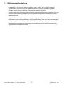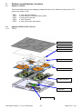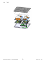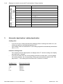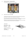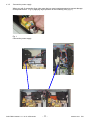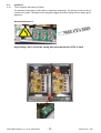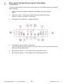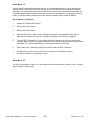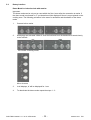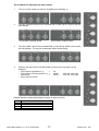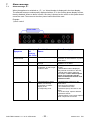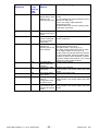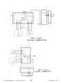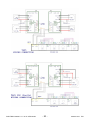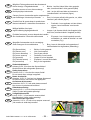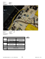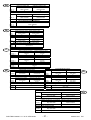
1
SERVICE MANUAL
COOKERS
Built-in hob
Induction
© Electrolux Distriparts
Muggenhofer Straße 135
D-90429 Nürnberg
Germany
Fax +49 (0)911 323 1022
DGS-TDS-N
08.08
Edition:
Publ.-Nr.:
599 531 041
685
EN
„TAP“
Table of contents
1.
ESD=electrostatic discharge ............................................................................................... 3
2.
2.1
2.2
2.2.1
2.2.2
2.2.3
2.2.4
2.3
2.4.
2.4.1
2.4.2
Software specifications, functions ....................................................................................... 4
Appliance variants ............................................................................................................... 4
Applaince build-up TAP versions ........................................................................................ 4
TAP1/2 ................................................................................................................................ 4
TAP3 ................................................................................................................................... 5
TAP4 ................................................................................................................................... 5
TAP5 ................................................................................................................................... 6
Control panels for induction zones with Touch Interface .................................................... 7
Symbol, explanation for display and keys ........................................................................... 7
Touch control - sensor zone symbols ................................................................................. 7
Displays for induction zones with Touch Interface / Rotary Interface ................................. 8
3.
Automatic deactivation / safety deactivation ....................................................................... 8
4.
4.1
4.1.1
4.1.2
4.2
4.2.1
4.2.2
4.2.3
Functional parts - Component data ..................................................................................... 9
Power board / Induction modul (MINI) ................................................................................ 9
Connection temperature sensor and induction coil ........................................................... 10
Connection power supply .................................................................................................. 11
Interfaces .......................................................................................................................... 12
Touch Interface with springs (Colibri) ................................................................................ 12
Touch Interface with touch pad (Inbuild in TAP3/4) .......................................................... 13
Rotary interface ................................................................................................................. 13
5.
5.1
5.2
Demo mode / Self test (Service mode) / Alarm Menu ....................................................... 14
Touch interfaces ................................................................................................................ 14
Rotary interface ................................................................................................................. 16
6.
6.1
6.2
6.3
6.4
6.5
Trouble Shooting ............................................................................................................... 18
Appliance not functional at all ........................................................................................... 18
Individual cooking zones do not work ............................................................................... 19
Other alarm symptoms ...................................................................................................... 20
Diagnostics Rotaries ......................................................................................................... 21
Testing Power component ................................................................................................ 22
7.
7.1
Alarm message ................................................................................................................. 23
Alarm message „E“ ........................................................................................................... 23
8.
Pot identification information ............................................................................................. 25
9.
Installation situation ........................................................................................................... 27
10.
Noise ................................................................................................................................. 27
11.
Wirings .............................................................................................................................. 28
12.
Spare part information - Universal Powerboard / ............................................................. 31
Information sheet 822 921 196 ......................................................................................... 31
Information sheet 822 921 195 ......................................................................................... 35
Changes .......................................................................................................................................... 38
DGS-TDS-N 08.08 U. H. / A. B. © Electrolux
-2-
599 531 041
EN
1.
ESD=electrostatic discharge
As the single electronic interfaces are not protected internally against statical electricity and are
partially open, you must pay attention to that, in case of a repair, there will be a potential
compensation via the housing of the appliance (touch it) in order to neutralize a possible
charging and to prevent a damaging of the affected electronic interface.
You also have to be careful with those electronics delivered as spare parts, which have to be put
out of the ESD protective package only after a potential compensation (discharge of possible
statical electricity).
If a potential compensation with an existing static electricity is not executed, it does not mean
that the electronic is demaged directly. Consequential damages may result due to the damaging
of internal structures which arise only in case of load through temperature and current.
Endangered are all assembly groups which are provided with control entries, wire paths lying
open and free-accessible processors.
DGS-TDS-N 08.08 U. H. / A. B. © Electrolux
-3-
599 531 041
EN
2
Software specifications, functions
2.1
Appliance variants
This Service Manual serve the repairing cooking hobs with 2 to 4 induction cooking zones. The
name of the range is TAP:
- TAP1
- TAP2
- TAP3
- TAP4
- TAP5
2.2
2.2.1
4 zone with two boosters
3 zone with two or three boosters; paella
2 zone plus 2 zone gas
2 zone (Domino)
4 zone and 2 zone with rotaries
Applaince build-up TAP versions
TAP1/2
Survace
Insulation
Coil sensors
Insulation layers
Coils with sensors
Power modules
Interface
Interface-Carrier
DGS-TDS-N 08.08 U. H. / A. B. © Electrolux
-4-
599 531 041
EN
2.2.2
TAP3
2.2.3
TAP4
DGS-TDS-N 08.08 U. H. / A. B. © Electrolux
-5-
599 531 041
EN
2.2.4
TAP5
DGS-TDS-N 08.08 U. H. / A. B. © Electrolux
-6-
599 531 041
EN
2.3
Control panels for induction zones with Touch Interface
Touch Control sensor zone symbols are differing from one brand to another, but they have
identical functions and arrangements.
Cooking Zone displays,
Timer Function
Display
Cooking level selection
Timer Display
Timer
On/Off with control
lamp
2.4.
2.4.1
Power function
Interlock
Symbol, explanation for display and keys
Touch control - sensor zone symbols
Sensor zone
Function
On / Off
Switch on or off appliance
Increase settings
Increase cooking level / time
Reduce settings
Reduce cooking level / time
Timer
Timer choice
Interlock
Control panel lock/unlock
Power
Power function switch on / off
DGS-TDS-N 08.08 U. H. / A. B. © Electrolux
-7-
599 531 041
EN
2.4.2
Displays for induction zones with Touch Interface / Rotary Interface
Display
Description
Cooking area is switched off
3.
Cooking levels
Cooking levels are set
Fault
Function failure occurs
Pot detection
Residual heat
Cooking tablewear is unsuitable or too small and/or it
is not put on.
Cooking area is still warm
Child safety function
Interlock/Child safety is on
Power
Power-function is switched off
Automatic Shut-Off
Safety cutoff is active
Automatic deactivation / safety deactivation
Cooking field
-
If you do not set a cooking intensity after switching ON the cooking zone within 10 s, the
cooking top platform automatically switches OFF.
If all cooking zones are switched OFF, the cooking top platform automatically deactivates
after ca. 10 s.
Induction cooking zones
-
If the recipient used is inappropriate, the display shows "F“ and the cooking zone display
goes dark after 2 minutes.
If you do not switch OFF one of the cooking zones after a certain time, or if you change
the cooking intensity, the corresponding cooking zone automatically switches OFF. Display shows "-“. The cooking zone must be set to "0" before it is reused.
Cooking level
Disconnection after
1-2
3-4
5
6-9
6 Hours
5 Hours
4 Hours
1,5 Hours
DGS-TDS-N 08.08 U. H. / A. B. © Electrolux
-8-
599 531 041
EN
4.
Functional parts - Component data
The configuration is always placed in the User Interface!
Sample illustration
4.1
Power board / Induction modul (MINI)
Two different power boards are used in this „TAP“ range. They are working with a Macs-Bus
communication. This requires a clear identification of all components.
For the customer service we have one universal Power board/ Induction modul. The spare part
number is 330 563 051/3 and it will be used for TAP1 hobs ---> TAP5 hobs.
With this Power board/ Induction modul you get the information sheet 822921196 (see chapter
12). Than you can find the needed information for the changement.
Technical data
Nominal voltage:
230 V
Nominal frequency: 50/60 Hz
Max wattage:
3,6 kw
Connection for cooking zone
Wattage per cooking zone max.:
Total wattage:
Ambient temperature:
DGS-TDS-N 08.08 U. H. / A. B. © Electrolux
3,1 kw
3,6 kw
T85
-9-
599 531 041
EN
4.1.1
Connection temperature sensor and induction coil
Shielding plate
Coil connection
Temperature
sensor
DGS-TDS-N 08.08 U. H. / A. B. © Electrolux
- 10 -
599 531 041
EN
4.1.2
Connection power supply
When you pull of connection lines, take care that you exert counterpressure to prevent damage
of the power board. E.g. by applying slight pressure to the bordering relay (fig. 1).
Fig. 1
Connection power supply
DGS-TDS-N 08.08 U. H. / A. B. © Electrolux
- 11 -
599 531 041
EN
4.2
4.2.1
Interfaces
Touch Interface with springs (Colibri)
The interface with springs is still based on capacitive technology. The springs must have direct
contact to the glass. The pads on the springs are bigger than the printing to have always good
alignment.
Sicherheitshinweis !!!
High Voltage: Don`t touch the spring with empowered hob (215V; 3,3mA)
DGS-TDS-N 08.08 U. H. / A. B. © Electrolux
- 12 -
599 531 041
EN
4.2.2
Touch Interface with touch pad (Inbuild in TAP3/4)
The touch pad is glued directly to the glass ceramic and connected with a foil cable via
connectors with the user interface. Be sure that the connectors are locked and the hooks are not
damaged. The user interface is clipped into a plastic frame which is glued to the glass ceramic.
4.2.3
Rotary interface
The interface with rotary is a traditional solution. The rotaries are connected to the interface
board. The position of the rotary is detected converted to level 0-P.
DGS-TDS-N 08.08 U. H. / A. B. © Electrolux
- 13 -
599 531 041
EN
5.
Demo mode / Self test (Service mode) / Alarm Menu
5.1
Touch interfaces
To enter the Demo mode / service mode / factory test menu, the following sequence of buttons
must be pressed:
1.
Hob is off. Press main switch continuously until display is going off (without
beep).
2.
Press the “+” and “ -” buttons (2a) of both front zones together (all 4 keys
togehter ) for about 3 seconds (-> short beep)
3.
Press the timer selection key (-> again short beep)
4.
The display (C) shows a “d” for demo mode
If you press the timer select key again you switch to “S” for service mode, another press
gets you to “E” the alarm menu!
5.
By pressing the button “+” of a cooking zone you activate the menu.
6.
By pressing the button “-“ of a cooking zone you deactivate the menu.
DGS-TDS-N 08.08 U. H. / A. B. © Electrolux
- 14 -
599 531 041
EN
Demo Mode “d”
If demo mode is activated the display with the „d“ shows additionally a dot. After selecting the
demo mode, the electronic goes to off. Now it can be used like usual but only without heater
activation. The deactivation of the demo mode is done in the same procedure as activating. After deactivating the demo mode the electronic must go off. Now the hob can be used in normal
mode. The demo mode is mains failure safe, status is saved in power board EEPROM.
Service Mode “S” Routine
1.
Show user interface SW version
2.
Show control SW version
3.
Show power SW version
4.
400V detection test: “400U” blink on displays until 400V is not applied. When 400V is
detected, the buzzer ring and “OU” is shown on display until 230V is not applied.
5.
Test all LED’s / Displays for 7 sec; during this time, booster is set on rear zones to test
sensors. When the time is elapsed, if the sensor are OK the test jump to the following step
otherwise “S” is shown alternatively on zones where the error occurred.
6.
Zone power test: a different power level is set on each zone for 2 seconds
7.
Pot detection: power level 9 is set on every zones for 10 seconds in order to
check pot detection by removing the load.
Alarm Mode “E”
The last 5 stored alarm codes (if >o) are displayed like an actual alarm, each for 5 sec., starting
with the oldest to the newest .
DGS-TDS-N 08.08 U. H. / A. B. © Electrolux
- 15 -
599 531 041
EN
5.2
Rotary interface
Demo Mode for induction hob with roatries
Important:
The demo mode can be only set or reset within the first 4 secs after the connection to mains. If
the demo mode is activated no „F“ pot detection will be displayed if there is no pot placed on the
cooking zone. The following procedure is the same for activation and deactiation of the demo
mode.
1.
Connect hob to mains.
2.
All displays are activated. Within 4 secs the 2nd knob from riht hand side is turned shortly
to the left limit.
60 cm with 4 cooking zones
80 cm 4-zones
3.
In all displays „d“ will be displayed for 1 sec.
4.
To deactivate the demo mode repeat the steps 1 - 3.
DGS-TDS-N 08.08 U. H. / A. B. © Electrolux
- 16 -
599 531 041
EN
Service Mode for induction hob with roatries
1.
Turn one of the roaties on and off. All displays are showing „0“.
2.
Turn the 1st and 2nd knob from left hand side or from top for 3 secs to the left
limit position.
60 cm with 3 cooking zones
60 cm with 4 cooking zones
3.
Turn the knobs 2 and 3 from riht hand side or from the top within 3 secs to the
left limit position. The service mode starts with a double beep.
4.
With the 3rd nob from the riht hand side or the top the next steps can be
switched
- SW Version of Interface e. g.
=
30.
- SW Version of Power boards e. g. =
4242 =
V 42 left, V 42 right
- Power SW
=
3434 =
V 34 left, V 34 right
- Exit of Service mode
Display interface variant with software version at start-up of hob:
A 430
b 430
C 430
d 430
E 430
60 cm
60 cm
60 cm
60 cm
80 cm
4-zones, 4 Power zones
4-zones, 1 Power zone
3-zones, 270 mm dual zones
3-zones, 210 mm, 1 Power zone
4-zones, 4 Power zones
DGS-TDS-N 08.08 U. H. / A. B. © Electrolux
- 17 -
599 531 041
EN
6.
Trouble Shooting
6.1
Appliance not functional at all
Appliance not functioning at all, cannot be switched on.
References (1) refer to the illustrations in chapter 6.5 Testing Power component
Alarm Symptom
Cooking Possible Alarm
Hob
Cause
Display
Alarm Remedying
House fuse triggered
None
(1) Test the pin assignment and
230VAC between N , Lines and earth on
the supply line.
See chapter 5.
Cooking field cannot
be switched on.
Incorrect connection at
the power connection
terminal.
Final induction phase
defect.
No mains voltage or
incorrect connection
(1 phase missing ->no
control voltage; N not
connected to terminal 4
and 5 not connected)
Connector of the cable
to the Touch Control /
Display not inserted.
(1) Test the pin assignment and
230VAC , Neutral, Line(s) and earth.
Both of the "N“s should be connected to
wall terminals.
Test connector at the filter and Touch
Control.
Reapply the mains voltage.
Fuse strip conductor burnt See Chapter 5.
out and/or final induction
phase defect
Touch control defect.
If 5VDC exist and power component already
replaced: replace the UI. Ensure that the
Touch pcb is well glued to the glass, and
that the connection wire is well inserted.
DGS-TDS-N 08.08 U. H. / A. B. © Electrolux
- 18 -
599 531 041
EN
6.2
Individual cooking zones do not work
Individual cooking zones do not work (partially) or work incorrectly or cannot be used.
Alarm Symptom Cooking Possible Alarm
Hob
Cause
Display
Pan does not heat
up.
Normal
cooking
phase
Flashing
"F“
No power on all hobs Normal
cooking
phase
Individual buttons
cannot be used or
cannot always be
used.
Normal
Cooking hob power
cooking
too low or not
provided for a longer phase
duration.
Pan in the border
area of the pan
detection and only
works with low power
Pan not detected.
Use different pot or this pot on a smaller
hob. See Chapter „Potdetection“
Touch Control defect.
1) See Chapter Interface
2) Should this not help, replace Touch
Control.
Incorrectly installed,
exhaust not possible
to the front.
See chapter installation situation
Unsuitable pots
(bottom bent)
Induction coil is not
applied to the glass
ceramic
See Chapter
Check whether the pots or pans are
suitable for induction
Coil not correctly
Check whether the coil lines are connected
connected.
and the torque has been adhered to.
Distance between coil Check whether the coil is applied to the
and glass ceramic too glass ceramic and whether the glass was
pushed was pushed down when screwing
large.
in position.
Demo mode
See Chapter Demo Mode
activated.
Fan does not start.
"H" in display when
cooking hob and
oven cold and
switched off.
"H“
DGS-TDS-N 08.08 U. H. / A. B. © Electrolux
Alarm Remedying
Temperature sensor
defect.
- 19 -
Check whether the glass ceramic was
pushed down when being screwed in
position and the coil has been correctly
positioned.
1) When setting a cooking phase >0, the
fan runs at a slow speed. If not, check the
fan for foreign bodies, remove these where
appropriate.
2) If necessary, replace fan.
3) Should this not succeed, replace power
component.
Replace corresponding coil with
temperature sensor. Also see Instructions
"E4“.
599 531 041
EN
6.3
Other alarm symptoms
Alarm
symptoms
Display
Buzzer defect
Individual display
elements do not
illuminate or do not
do so continuously.
Pots cause noises
DGS-TDS-N 08.08 U. H. / A. B. © Electrolux
Possible Alarm
Cause
Alarm Remedying
Touch control
defect.
Defective display
elements
Replace User interface.
Unsuitable pots.
Normal sound level
See Chapter Noise
Interference noises result from the high
working frequency of the induction. This can
vary from pan to pan.
When measured in operation pursuant to
EN60335 §11-3 pursuant to EN60704 with 4
pots <47dBA.
A pot with boiling water has approx. 6062dBA.
- 20 -
Replace User interface.
599 531 041
EN
6.4
Diagnostics Rotaries
Alarm symptom
Display E – F
alternating
In the test program, the
displays of one side
flash alternatively with
"S".
Display E4 alternating
C 7 alternating in the
displays of one module
side
E 8 alternating in the
R.H. displays
No function of displays
Component
Controller pertaining to
the affected display is
outside tolerance limits
Sensors on a module
are mixed up
Alarm Remedying
Replace controller of
the affected display
Sensors of the affected
cooking zone are not
plugged or defect
Coil is not connected
or defect
Plug or replace sensor
Commissioning or
during operation
Connect and/or replace
coils
Commissioning or
during operation
Bus cable to the R.H.
module is not
connected or defect
Bus cable to the L.H.
module is not
connected or defect
L.H. module wrong
ANC (no bridge)
Modules are not
connected or defect
Connect or replace bus
cable
Commissioning or
during operation
Connect or replace bus
cable
Commissioning or
during operation
Install the correct
module
Check whether twice
the same ANC –
replace modules or
replace L.H. module
Replace interface
Commissioning
Interface defect
Power parameters
outside tolerance
Coils are incorrectly
connected, modules
are mixed up
Display not belonging
to the rotary button is lit
Lines are mixed up on
two controllers
DGS-TDS-N 08.08 U. H. / A. B. © Electrolux
- 21 -
Plug or replace sensor
Verify coil connection,
bridge on module
should be plugged on
left side!
Change lines
Detection
Rotary test, 30 sec.
After the cooking zone
was switched OFF
Commissioning or
during operation
Commissioning or
during operation
Commissioning or
during operation
Commissioning
Automatic tests will not
result in detection on
the right side
599 531 041
EN
6.5
Testing Power component
1.
When alarm messages and disabled zones exist („E“ in cooking phase display), please
make a note of the power component which is affected.
Check power lines and connection to user interface is connected.
2.
If IGBT has become shorted, this normally means that the IGBT housing is damaged.
Replace power component.
Measure resistance at the IGBTs
Pin1-Pin2 or Pin2-Pin3
>50kOhm = Okay
<50Ohm = power component defect & replace
Only replace the affected power component .
S12 = right power component
S11 = left power component
IGBT
DGS-TDS-N 08.08 U. H. / A. B. © Electrolux
- 22 -
599 531 041
EN
7.
Alarm message
7.1
Alarm message „E“
When the appliance is switched on, „E“ / „xx“ Alarm Number is displayed in the timer display.
The affected zones are subsequently displayed with an „E“ in the cooking phase display and are
thereby disabled. When an alarm is active, the relay is opened so the zones on this power board
cannot be used. The zones on the other power board can still be used.
Example:
1) Error code 8
Error code
Alarm
Symptom
Display in Possible Alarm
the
Cause
Cooking
Hob Timer
Alarm display in the "E1“
Touch Control.
"E2“
"E3“
"E4“
DGS-TDS-N 08.08 U. H. / A. B. © Electrolux
Alarm Remedying
Zone temperature too high Temperature too high due to bad
connection on zone sensors, or power
board defect.
User interface temperature Temperature too high due to
too high
installation or UI defect.
400 VAC detected, instead 1) verify power lines connection, on
of 230VAC, on left or right the wall
module or both
2) Should alarm still be displayed,
verify internal connection in the hob,
3 Should alarm still be displayed,
See Chapter Fehler! Verweisquelle
konnte nicht gefunden werden.
Fehler! Verweisquelle konnte nicht
gefunden werden.
Coil temperature sensor
defect, not correctly
connected, or broken,
display in the
corresponding zone.
- 23 -
1) Inspecting the contacts on the
power board.
Is the connector inserted?
2) The resistance at room
temperature (25°C) amounts to 100
kOhm..
If not in this range, replace affected
temperature sensor.
3) Should above not succeed, replace
power component concerned.
599 531 041
EN
Alarm
Symptom
Display
in the
Cooking
Field
Timer
Possible Alarm
Causes
Alarm Remedying
"E5“
Coil temperature
sensor defect, short,
display in the
corresponding zone.
1) Inspecting the contacts on the power
board.
2) The resistance at room temperature (25°C)
amounts to 100 kOhm..
If not in this range, replace affected
temperature sensor.
3) Should above not succeed, replace power
component concerned.
"E6“
Communication
defect inside power
board
Alarm Temperature
sensor on the heat
sink at the power
component
Communication
interference
between power and
User interface.
Replace identified power board.
"E7”
"E8“
"E9“
"EA“
"EB“
"EC“
"ED“
DGS-TDS-N 08.08 U. H. / A. B. © Electrolux
Communication
defect inside user
interface
Configuration data
defect/false
15V power supply
out of range
Wrong compatibility
code on
configuration data
for power board
SW compatibility
error between user
interface and power
board
- 24 -
Verify connector, if not OK, or replace affected
power component.
1) if left, Verify the power wiring in the wall. If
OK, Reinsert connector of UI,
Or replace cable. If not OK go to 3)
2) if Right, Verify middle connection of cable
of UI, replace cable, if not OK go to 3),
3) take cable of left power board and connect
to right power board, with a test cable longer
connect UI right to power board left. A) same
as before change User interface, “E6” crossed
change the power board identified.
Replace User interface.
Replace User interface.
If the problem is not solved, replace the power
board.
Replace the power board.
Replace User interface.
If the problem is not solved, replace the power
board.
Replace User interface.
If the problem is not solved, replace the power
board.
599 531 041
EN
8.
Pot identification information
Suitable pot materials:
Steel enamel
Stainless steel (with magnet. bottom)
Aluminium (with magnet. bottom)
Cast iron
Unsuitable materials:
Aluminium (à too much power)
Copper
Stainless steel (not magnetic)
Glass
Ceramic
The pot detection is designed for the following diameters:
Nominal burner ∅ [mm]
Minimum pot bottom ∅
instruction manual [mm]
145
180
210
125
145
180
DGS-TDS-N 08.08 U. H. / A. B. © Electrolux
- 25 -
Minimum pot bottom ∅
adjusted with steel plate
[mm]
100
120
140
599 531 041
EN
With regard to Ind. G4, the same diameter is stipulated in the
instruction manuals as for the previous model. However, the
real diameter which still functions is much smaller.
The performance for different pots can very by as much as +/
- 10-15%.
-
As reference pots, we recommend enamelled steel pots
(e.g. Silit).
-
2-3 mm thick round steel plates in various diameters are
very suitable for testing the pot detection function.
-
Sandwich bottoms can cause very unpleasant noises if
they are not correctly pressed. The same is the case
with regard to handles which are a little loose.
-
With regard to stainless steel pots with sandwich
bottoms, the diameter of the magnetic part of the pot
bottom is decisive.
-
An additional influencing factor is the vertical distance
from the coil, i.e. an uneven sandwich bottom has a negative effect on the power consumption. The effect is
exactly the same if the induction coil is not pressed on
the glass ceramic.
DGS-TDS-N 08.08 U. H. / A. B. © Electrolux
- 26 -
599 531 041
EN
9.
Installation situation
The performance could be lower if hot air will be sucked.
Air inlet
Min. 5 mm
Min. 20mm
10.
Noise
There are different reasons for noise and different sounds witch you can hear.
The maximum noise you cant get with pots with sandwich structure and running with maximum
power on two zones at the same time. Try to use a different pot (enamelled steel instead of
stainless steel) and change the power settings a little bit. The level of filling in the pot and the
type of food is sometimes direct linked to noise.
See attached customer information
Cook comport on highest level
Twice as fast heating like conventional cool top platforms
(1)
(2)
(3)
(4)
(5)
Pan base
Caramic glass
Magnetic field
Exhaust
Induction coil
When extremely fast heating-up the induction hob results vibrations in the pan base (1), which
can cause noises with some pots.
From the very high power of the induction hob results warmth, which must be cooled with an
exhaust (4).
DGS-TDS-N 08.08 U. H. / A. B. © Electrolux
- 27 -
599 531 041
EN
11.
Wirings
DGS-TDS-N 08.08 U. H. / A. B. © Electrolux
- 28 -
599 531 041
EN
DGS-TDS-N 08.08 U. H. / A. B. © Electrolux
- 29 -
599 531 041
EN
DGS-TDS-N 08.08 U. H. / A. B. © Electrolux
- 30 -
599 531 041
EN
12.
Spare part information - Universal Powerboard /
Information sheet 822 921 196
Hinweiszettel
Information sheet
Fiche d'information
Foglio istruzioni
Attentie
Hoja informativa
822 921 196
DE
Induktionsmodul, ET.-Nr.: 330 563 051/3 („MINI ---> MINI“)
Dieses Induktionsmodul ersetzt Ihr bisher eingebautes Induktionsmodul. Die Anschlüsse für die
Induktionspulen und Temperatursensoren, können 1:1übernommen werden. Je nach Kochfeldtyp ist Ihr defektes Induktionsmodul mit der Brücke 1 oder der Brücke 2 ausgestattet. Beim
Austausch muß folgendes beachtet werden:
GB
Induction module, SP.-No.: 330 563 051/3 („MINI ---> MINI“)
This induction modules replaces your previously installed induction module. The connections for
the induction coils and temperature sensors can be accepted 1:1. Your defective induction
module is equipped with Link 1 or Link 2, depending on the hob type. Must be taken into
account when replacing:
FR
Module à induction, n° de réf. 330 563 051/3 („MINI ---> MINI“)
Ce module à induction remplace votre module à induction intégré jusqu’à présent portant.
Les raccordements pour les bobines à induction et les capteurs de température peuvent être
repris à l’identique. En fonction du type de table de cuisson, votre module à induction
défectueux sera équipé du fil jarretière 1 ou du fil jarretière 2. Lors du remplacement, veuillez
tenir compte des éléments suivants :
IT
330 563 051/3 („MINI ---> MINI“)330 563 051/3 („MINI ---> MINI“)
Questo modulo a induzione sostituisce l’attuale modulo a induzione. Gli attacchi per la bobina
d’induzione e i sensori della temperatura possono essere accettati 1:1. Il vostro modulo a
induzione difettoso è dotato del ponticello 1 o del ponticello 2 secondo il tipo di piano di cottura.
In caso di sostituzione si deve osservare quanto segue:
SE
Induktionsmodul, ET.-nr.: 330 563 051/3 („MINI ---> MINI“)
Denna induktionsmodul ersätter den hittills inbyggda induktionsmodulen. Anslutningarna för
induktionsspolarna och temperatursensorerna kan övertas 1:1. Beroende på induktionshällens
typ är den defekta induktionsmodulen utrustad med jumper 1 eller jumper 2. Vid byte måste
följande beaktas:
NL
Inductiemodule, onderdeelnr.: 330 563 051/3 („MINI ---> MINI“)
Deze inductiemodule vervangt uw momenteel ingebouwde inductiemodule. De aansluitingen
voor de inductiespoelen en temperatuursensoren kunnen 1:1 worden overgenomen. Afhankelijk
van het type kookplaat is uw defecte inductiemodule met brug 1 of brug 2 uitgerust. Bij de
vervanging dient het volgende in acht te worden genomen:
Módulo de inducción, N° de la pieza de recambio: 330 563 051/3 („MINI ---> MINI“) ES
Este módulo de inducción reemplaza al módulo de inducción montado hasta ahora. Las
conexiones para las bobonas de inducción y los sensores de la temperatura pueden ser
aplicados 1:1. Según el tipo de zona de cocción, su módulo de inducción averiado está dotado
con el puente 1 ó el puente 2. En el cambio debe observarse lo siguiente:
DGS-TDS-N 08.08 U. H. / A. B. © Electrolux
- 31 -
599 531 041
EN
Brücke 1
Link 1
Fil jarretière 1
Ponticello 1
Jumper 1
Brug 1
Puente 1
4-Zonen Induktionskochfeld
Induk tionsmodul link s
Induk tionsmodul rechts
Brücke 1
Brücke 2
Brücke 1
Brücke 2
DE
Vom Altteil übernehmen
x
x
x
3-Zonen Induktionskochfeld
Induk tionsmodul link s
Induk tionsmodul rechts
Vom Altteil übernehmen
x
x
Vom Altteil übernehmen
2-Zonen Induktionskochfeld
Vom Altteil übernehmen
Brücke 1
x
Brücke 2
4-Zonen-Kochfeld mit 2 Induktionskochzonen
x
x
Brücke 1
Brücke 2
Brücke 2
Link 2
Fil jarretière 2
Ponticello 2
Jumper 2
Brug 2
Puente 2
4-Zone Induction Hob
Induction module left
Induction module right
Link 1
Link 2
Link 1
Link 2
GB
Take over from old part
x
x
x
3-Zone Induction Hob
Induction module left
Induction module right
Take over from old part
x
x
Take over from old part
2-Zone Induction Hob
Take over from old part
Link 1
x
Link 2
4-Zone hob with 2 Induction Hob
x
x
Link 1
Link 2
Plaque de cuisson à induction 4 zones
Module d'induction gauche Module d'induction droit
pont 1
pont 2
pont 1
pont 2
FR
Relayer de la vieille pièce
x
x
x
Plaque de cuisson à induction 3 zones
Module d'induction gauche Module d'induction droit
Relayer de la vieille pièce
x
x
Relayer de la vieille pièce
Plaque de cuisson à induction 2 zones
Relayer de la vieille pièce
pont 1
Enlever de la pièce détachée
pont 2
Plan de cuisson 4 zones avec 2 zones de cuisson à induction
x
x
pont 1
pont 2
DGS-TDS-N 08.08 U. H. / A. B. © Electrolux
- 32 -
599 531 041
EN
Piano di cottura a induzione a 4 zone
Modulo a induzione a sinistra
Modulo a induzione a destra
IT
Ponticello 1
Ponticello 2
Ponticello 1
Ponticello 2
Prendere dalla parte vecchia
x
x
x
Piano di cottura a induzione a 3 zone
Modulo a induzione a sinistra
Modulo a induzione a destra
Prendere dalla parte vecchia
x
x
Prendere dalla parte vecchia
Piano di cottura a induzione a 2 zone
Prendere dalla parte vecchia
Ponticello 1
x
Ponticello 2
4-zone piano di cottura con piano di cottura a induzione a 2 zone
x
x
Ponticello 1
Ponticello 2
SE
Induktionshäll med fyra zoner
Induk tionsmodul vänster
Induk tionsmodul höger
Jumper 1
Jumper 2
övertas från den gamla delen
x
x
x
Induktionshäll med tre zoner
Induk tionsmodul vänster
Induk tionsmodul höger
Jumper 1
Jumper 2
övertas från den gamla delen
x
x
övertas från den gamla delen
Induktionshäll med två zoner
övertas från den gamla delen
Jumper 1
x
Jumper 2
4-Zoner-Kokfält med Induktionshäll med två zoner
NL
x
x
Jumper 1
Jumper 2
Inductiekookplaat 4 zones
Inductiemodule link s
Inductiemodule rechts
Brug 1
Brug 2
Brug 1
Brug 2
van oud ond. overnemen
x
x
x
Inductiekookplaat 3 zones
Inductiemodule link s
Inductiemodule rechts
van oud ond. overnemen
x
x
van oud ond. overnemen
Inductiekookplaat 2 zones
van oud ond. overnemen
Brug 1
x
Brug 2
4-zones kookveld med Inductiekookplaat 2 zones
ES
Brug 1
Brug 2
x
x
4 Zonas de cocción por inducción
Módulo de inducción a la izquierda
Módulo de inducción a la derecha
Puente 1
Tomarlo de la pieza antigua
Puente 2
x
3 Zonas de cocción por inducción
Módulo de inducción a la izquierda
x
x
Módulo de inducción a la derecha
Puente 1
Tomarlo de la pieza antigua
Puente 2
x
2 Zonas de cocción por inducción
x
Tomarlo de la pieza antigua
Tomarlo de la pieza antigua
Puente 1
x
Puente 2
4-Zonas-panel de cocción con 2 Zonas de cocción por inducción
Puente 1
Puente 2
x
x
DGS-TDS-N 08.08 U. H. / A. B. © Electrolux
- 33 -
599 531 041
EN
DE
GB
FR
IT
SE
ES
NL
Mögliche Fehlerquellen nach dem Austausch:
Keine Anzeige / Eingabeelektronik
=
Brücke 1 auf der linken Seite nicht gesteckt,
oder „Interface Kabel“ nicht gesteckt (Bild)
Possible sources of error after exchange:
No display/input electronics
=
Link 1 on the left-hand side not inserted or
„InterfaceCable“ not inserted (figure)
Causes d’erreur éventuelles après remplacement :
pas d’affichage / électronique d’entrée =
Pont 1 n’est pas enfiché côté gauche, ou „câble
interface“ pas enfiché (figure)
Possibili fonti di guasto dopo la sostituzione:
Nessun indicatore / elettronica d’immissione =
Ponticello 1 non applicato sul lato sinistro,
oppure “cavo interfaccia“ non inserito
(figura)
Möjliga felkällor efter bytet:
Ingen indikering/ingångselektronik
=
Jumper 1 på vänster sida är inte ikopplad, eller
så är inte „Interface-kabeln“ ikopplad (se bild)
Posibles fuentes de errores después del cambio:
Sin visualización / Electrónica de entrada
=
El puente 1 en el lado izquierdo no está
enchufado o el „cable de interfaz“ no está
enchufado (Fig.)
Mogelijke foutoorzaken na de vervanging:
Geen weergave-/invoerelektronica
=
Brug 1 aan de linkerzijde niet ingestoken of
interfacekabel niet ingestoken (afbeelding)
E4 (Sensorfehler)
E4 (Sensor error)
E4 (erreur détecteur)
E4 (errore sensore)
E4 (sensorfel)
E4 (Falla del sensor)
E4 (sensorfout)
DE
GB
FR
IT
SE
NL
ES
=
=
=
=
=
=
=
Brücke 2 nicht gesteckt
Link 2 not inserted
Pont 2 pas enfiché
Ponticello 2 non inserito
Jumper 2 är inte ikopplad.
El puente 2 no está enchufado
Brug 2 niet ingestoken
Sicherheitshinweis!
Achtung 215V; 3,3mA an den Sensorfeldern!
Nicht berühren bei anliegender Spannung!
Safety Instructions
Caution: 215 V, 3.3 mA at the sensor fields!
Do not touch when voltage is applied!
Notes de sécurité
Attention 215 V, 3.3 mA sur les champs détecteurs!
Ne pas toucher si une tension est appliquée!
Avvertenza di sicurezza
Attenzione 215 V, 3,3 mA sulla piastra sensori!
Non toccare in presenza di tensione!
Säkerhetsanvisning
Varning! 215 V, 3,3 mA vid sensorområdena!
Vidrör ej under anliggande spänning!
Veiligheidsinstructie
Let op: 215 V, 3,3 mA aan de sensorvelden!
Niet aanraken, indien onder spanning!
Indicaciones de seguridad
¡Atención, 215 V, 3,3 mA en los campos sensores!
¡No tocarlos si están bajo tensión!
DGS-TDS-N 08.08 U. H. / A. B. © Electrolux
- 34 -
599 531 041
EN
Information sheet 822 921 195
Hinweiszettel
Information sheet
Fiche d'information
Foglio istruzioni
Attentie
Hoja informativa
822 921 195
DE
Induktionsmodul, ET.-Nr.: 330 563 050/5 („MINI ---> TEIS“)
Dieses Induktionsmodul ersetzt Ihr bisher eingebautes Induktionsmodul 387 169 501/5. Die
Anschlüsse für die Induktionspulen und den Temperatursensoren können 1:1übernommen
werden. Das erhaltene Induktionsmodul ist zusätzlich mit zwei Steckbrücken ausgestattet. Je
nach Kochfeldtyp muß bei Austausch folgendes beachtet werden:
GB
Induction module, SP.-No.: 330 563 050/5 („MINI ---> TEIS“)
This induction modules replaces your previously installed induction module 387 169 501/5. The
connections for the induction coils and temperature sensors can be accepted 1:1. The received
induction module is additionally equipped with two link plugs. Depending on the hob type, the
following must be taken into account when replacing:
FR
Module à induction, n° de réf. 330 563 050/5 („MINI ---> TEIS“)
Ce module à induction remplace votre module à induction intégré jusqu’à présent portant le
n°387 169 501/5. Les raccordements pour les bobines à induction et les capteurs de
température peuvent être repris à l’identique. Le module à induction obtenu est équipé, en
outre, de deux fils jarretières. En fonction du type de table de cuisson, il faut tenir compte des
éléments suivants :
IT
Modulo a induzione, ET. n°: 330 563 050/5 („MINI ---> TEIS“)
Questo modulo a induzione sostituisce l’attuale modulo a induzione 387 169 501/5. Gli attacchi
per la bobina d’induzione e i sensori della temperatura possono essere accettati 1:1. Il modulo a
induzione è dotato anche di due ponticelli ad innesto. In caso di sostituzione si deve osservare
quanto segue in base al tipo di piano di cottura:
SE
Induktionsmodul, ET.-nr.: 330 563 050/5 („MINI ---> TEIS“)
Denna induktionsmodul ersätter den hittills inbyggda induktionsmodulen 387 169 501/5.
Anslutningarna för induktionsspolarna och temperatursensorerna kan övertas 1:1. Den erhållna
induktionsmodulen är utrustad med två jumprar. Beroende på induktionshällens typ måste
följande beaktas vid byte:
NL
Inductiemodule, onderdeelnr.: 330 563 050/5 („MINI ---> TEIS“)
Deze inductiemodule vervangt uw momenteel ingebouwde inductiemodule 387 169 501/5. De
aansluitingen voor de inductiespoelen en temperatuursensoren kunnen 1:1 worden
overgenomen. De ontvangen inductiemodule is aanvullend met twee steekbruggen uitgerust.
Afhankelijk van het type kookplaat dient bij de vervanging het volgende in acht te worden
genomen:
Módulo de inducción, N° de la pieza de recambio: 330 563 050/5 („MINI ---> TEIS“) ES
Este módulo de inducción reemplaza al módulo de inducción 387 169 501/5 montado hasta
ahora. Las conexiones para las bobonas de inducción y los sensores de la temperatura pueden
ser aplicados 1:1. El módulo de inducción contenido está dotado adicionalmente con 2 puentes
enchufables. Según el tipo de zona de cocción se tiene que observar lo siguiente al efectuar el
cambio:
DGS-TDS-N 08.08 U. H. / A. B. © Electrolux
- 35 -
599 531 041
EN
Brücke 1
Jumper 1
Link 1
Brug 1
Fil jarretière 1
Puente 1
Ponticello 1
Brücke 2
Link 2
Fil jarretière 2
Ponticello 2
Jumper 2
Brug 2
Puente 2
4-Zonen Induktionskochfeld
Induk tionsmodul link s
Induk tionsmodul rechts
Brücke 1
Brücke 2
Brücke 1
Brücke 2
Brücke 1
Brücke 2
DE
stecken lassen
stecken lassen
x
x
3-Zonen Induktionskochfeld
Induk tionsmodul link s
Induk tionsmodul rechts
stecken lassen
stecken lassen
x
einsetzen
Mixed Induktionskochfeld Gas/ Elektro
stecken lassen
x
DGS-TDS-N 08.08 U. H. / A. B. © Electrolux
- 36 -
599 531 041
EN
4-Zone Induction Hob
Induction module left
Induction module right
GB
Link 1
Link 2
leave inserted
leave inserted
X
X
3-Zone Induction Hob
Induction module left
Induction module right
Link 1
Link 2
leave inserted
leave inserted
X
attach
Mixed Induction Hob Gas/Electric
leave inserted
X
Link 1
Link 2
Plaque de cuisson à induction 4 zones
Module d'induction gauche Module d'induction droit
FR
pont 1
pont 2
pont 1
pont 2
laisser enfiché
laisser enfiché
X
X
Plaque de cuisson à induction 3 zones
Module d'induction gauche Module d'induction droit
laisser enfiché
laisser enfiché
X
attacher
Plaque de cuisson mixte induction gaz/électrique
laisser enfiché
X
pont 1
pont 2
IT
Piano di cottura a induzione a 4 zone
Modulo a induzione a sinistra
Modulo a induzione a destra
Ponticello 1
Ponticello 2
applicare
applicare
X
X
Piano di cottura a induzione a 3 zone
Modulo a induzione a sinistra
Modulo a induzione a destra
Ponticello 1
Ponticello 2
Ponticello 1
Ponticello 2
applicare
applicare
X
attaccare
Piano di cottura a induzione misto gas/ elettrico
applicare
X
Inductiekookplaat 4 zones
Inductiemodule link s
Inductiemodule rechts
Induktionshäll med fyra zoner
Induk tionsmodul vänster
Induk tionsmodul höger
SE
Jumper 1
Jumper 2
ska sitta kvar
ska sitta kvar
X
X
Induktionshäll med tre zoner
Induk tionsmodul vänster
Induk tionsmodul höger
Brug 1
Brug 2
laten zitten
laten zitten
X
X
Inductiekookplaat 3 zones
Inductiemodule link s
Inductiemodule rechts
laten zitten
laten zitten
X
vastmaken
Gemengde inductiekookplaat gas/elektro
Jumper 1
Jumper 2
ska sitta kvar
ska sitta kvar
X
stick in
Mixad induktionshäll gas/el
Brug 1
Brug 2
Jumper 1
Jumper 2
ska sitta kvar
X
Brug 1
Brug 2
cocción por inducción
Módulo de inducción a la izquierda
Puente 1
dejar enchufado
Puente 2
X
cocción por inducción
Módulo de inducción a la izquierda
Puente 1
dejar enchufado
Puente 2
X
nducción mixta gas/electricidad
Puente 1
Puente 2
DGS-TDS-N 08.08 U. H. / A. B. © Electrolux
NL
laten zitten
X
Módulo de inducción a la derecha
ES
dejar enchufado
X
Módulo de inducción a la derecha
dejar enchufado
fijar
dejar enchufado
X
- 37 -
599 531 041
EN
Changes
Page 35 - 38 changed
DGS-TDS-N 08.08 U. H. / A. B. © Electrolux
- 38 -
599 531 041
EN