1
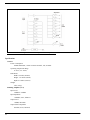
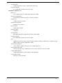
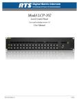
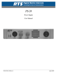
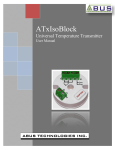
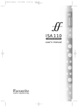
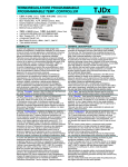
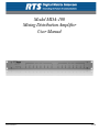
Model MDA-100
Mixing Distribution Amplifier
User Manual
9350710400 Rev F
12/2009
Proprietary Notice
Shipping to the Manufacturer
The product information and design disclosed herein were originated by
and are the property of Bosch Security Systems, Inc. Bosch reserves all
patent, proprietary design, manufacturing, reproduction, use and sales
rights thereto, and to any article disclosed therein, except to the extent
rights are expressly granted to others.
All shipments of product should be made via UPS Ground, prepaid (you
may request from Factory Service a different shipment method). Any
shipment upgrades will be paid by the customer. The equipment should
be shipped in the original packing carton. If the original carton is not
available, use any suitable container that is rigid and of adequate size. If
a substitute container is used, the equipment should be wrapped in paper
and surrounded with at least four (4) inches of excelsior or similar
shock-absorbing material. All shipments must be sent to the following
address and must include the Proof of Purchase for warranty repair.
Upon completion of any repair the equipment will be returned via
United Parcel Service or specified shipper, collect.
Copyright Notice
Copyright 2009 by Bosch Security Systems, Inc. All rights reserved.
Reproduction, in whole or in part, without prior written permission from
Bosch is prohibited.
Warranty Notice
See the enclosed warranty card for further details.
Customer Support
Factory Service Department
Bosch Security Systems, Inc.
8601 East Cornhusker Hwy.
Lincoln, NE 68507 U.S.A.
Attn: Service
Technical questions should be directed to:
Customer Service Department
Bosch Security Systems, Inc.
12000 Portland Avenue South
Burnsville, MN 55337 USA
[email protected]
Telephone: 800-392-3497
Fax: 800-323-0498
Technical Questions EMEA:
Bosch Security Systems Technical Support EMEA
http://www.rtsintercoms.com/contact_main.php
Return Shipping Instructions
Customer Service Department
Bosch Security Systems, Inc. (Lincoln, NE)
Telephone: 402-467-5321
Fax: 402-467-3279
Factory Service: 800-553-5992
Please include a note in the box which supplies the company name,
address, phone number, a person to contact regarding the repair, the type
and quantity of equipment, a description of the problem and the serial
number(s).
THE LIGHTNING
FLASH AND
ARROWHEAD
WITHIN THE TRIANGLE IS A WARNING
SIGN ALERTING
YOU OF “DANGEROUS VOLTAGE”
INSIDE THE PRODUCT.
CAUTION: TO REDUCE THE
RISK OF ELECTRIC SHOCK,
DO NOT REMOVE COVER. NO
USER-SERVICABLE PARTS
INSIDE. REFER SERVICING TO
QUALIFIED SERVICE PERSONNEL.
THE EXCLAMATION POINT
WITHIN THE
TRIANGLE IS A
WARNING SIGN
ALERTING YOU
OF IMPORTANT
INSTRUCTIONS
ACCOMPANYING THE PRODUCT
SEE MARKING ON BOTTOM/BACK OF PRODUCT
WARNING: APPARATUS SHALL NOT BE EXPOSED TO DRIPPING OR
SPLASHING AND NO OBJECTS FILLED WITH LIQUIDS, SUCH AS VASES,
SHALL BE PLACED ON THE APPARATUS.
WARNING: THE MAIN POWER PLUG MUST REMAIN READILY OPERABLE.
CAUTION: TO REDUCE THE RISK OF ELECTRIC SHOCK, GROUNDING OF
THE CENTER PIN OF THIS PLUG MUST BE MAINTAINED.
WARNING: TO REDUCE THE RISK OF FIRE OR ELECTRIC SHOCK, DO NOT
EXPOSE THIS APPRATUS TO RAIN OR MOISTURE.
WARNING: TO PREVENT INJURY, THIS APPARATUS MUST BE SECURELY
ATTACHED TO THE FLOOR/WALL/RACK IN ACCORDANCE WITH THE
INSTALLATION INSTRUCTIONS.
This product is AC only.
Important Safety Instructions
1.
Read these instructions.
2.
Keep these instructions.
3.
Heed all warnings.
4.
Follow all instructions.
5.
Do not use this apparatus near water.
6.
Clean only with dry cloth.
7.
Do not block any ventilation openings. Install in accordance with the
manufacturer’s instructions.
8.
Do not install near any heat sources such as radiators, heat registers, stoves,
or other apparatus (including amplifiers) that produce heat.
9.
Do not defeat the safety purpose of the polarized or grounding-type plug. A
polarized plug has two blades with one wider than the other. A grounding
type plug has two blades and a third grounding prong. The wide blade or the
third prong are provided for your safety. If the provided plug does not fit into
your outlet, consult an electrician for replacement of the obsolete outlet.
10.
Protect the power cord from being walked on or pinched particularly at
plugs, convenience receptacles, and the point where they exit from the
apparatus.
11.
Only use attachments/accessories specified by the manufacturer.
12.
Use only with the cart, stand, tripod, bracket, or table specified by the
manufacturer, or sold with the apparatus. When a cart is used, use caution
when moving the cart/apparatus combination to avoid injury from tip-over.
13.
Unplug this apparatus during lightning storms or when unused for long
periods of time.
14.
Refer all servicing to qualified service personnel. Servicing is required when
the apparatus has been damaged in any way, such as power-supply cord or
plug is damaged, liquid has been spilled or objects have fallen into the
apparatus, the apparatus has been exposed to rain or moisture, does not
operate normally, or has been dropped.
Safety Summary
Power Source
This equipment is designed to operate from an AC power source, as described in the electrical specifications.
Grounding
The chassis of this product is grounded through the grounding pin of the line cord. To avoid electrical shock, with the power
off, plug the line cord into a properly wired receptacle before making any input or output connections with other devices. Use
only the line cord specified for your unit. Ensure the line cord is in good condition and free of kinks.
Caution
CAUTION: A protective ground connection through the grounding conductor of the line cord is essential for safe operation.
Fusing
This product is fitted with a fuse. All fuse replacement related instructions are located in the service manual.
5
6
Table
of
Contents
IMPORTANT SAFETY INSTRUCTIONS ...........................................................................................................................................3
Power Source .............................................................................................................................................................5
Grounding .................................................................................................................................................................5
Caution ......................................................................................................................................................................5
Fusing ........................................................................................................................................................................5
INTRODUCTION ........................................................................................................................................ 7
Description and Specifications ..................................................................................................................................7
DESCRIPTION ............................................................................................................................................................................7
SPECIFICATIONS .......................................................................................................................................................................8
INSTALLATION ........................................................................................................................................ 11
Preparation .............................................................................................................................................................11
Power Connection ...................................................................................................................................................11
Audio Connections ..................................................................................................................................................12
J1 CONNECTOR ......................................................................................................................................................................12
J2 CONNECTOR ......................................................................................................................................................................13
J3 CONNECTOR ......................................................................................................................................................................13
J4 CONNECTOR ......................................................................................................................................................................14
J 5 CONNECTOR .....................................................................................................................................................................14
J6 CONNECTOR ......................................................................................................................................................................15
J7 CONNECTOR ......................................................................................................................................................................15
Audio Level Settings ................................................................................................................................................16
SUMMING AMPLIFIER ..............................................................................................................................................................16
DISTRIBUTION AMPLIFIER .......................................................................................................................................................16
CHAPTER 1
Introduction
Description and Specifications
Description
The MDA-100 Mixing and Distribution Amplifier contains an 8 x 1 summing amplifier (also known as a mixer) and a 1 x 8
distribution amplifier in a case that is 1 RU (Rack Unit) high. The MDA-100 is useful, for example, in CCU (Camera
Control), where multiple camera operators have to talk and listen to one master control location. In this application, audio from
each camera, up to eight (8), is fed to one of the summing amplifier inputs of the MDA-100. All eight (8) audio inputs are
summed and fed to the master controller input. The return audio path from the master controller back to the individual cameras
is accomplished using the distribution amplifier, which takes the single audio output from the master controller and distributes
it to each of the eight camera outputs.
The gain of each summing amplifier input may be individually adjusted by a trimmer on the front panel of the MDA-100.
There is also an output adjustment trimmer located inside the MDA-1000 to adjust the final output level of the summing
amplifier. The summing amplifier output is a 60 Ohm voltage source.
The distribution amplifier has a separate output level trimmer for each output. These trimmers are located on the front panel.
All the outputs are 60 Ohm voltage sources. The input impedances may be set for bridging (20 kOhms), 150 Ohms, or 600
Ohms, selected by rear panel jumpers.
The MDA-100 fits into a standard 19” (483mm) equipment rack. The power entry module is an IEC approved type, which
contains a line voltage switch, a line filter, a fuse holder, and a line cord socket connector. The line voltage switch may be set
for either 105/125Vac, 50/60Hz, or 210/250Vac, 50/60Hz supply voltages. The MDA-100 features a torroidal-transformer
power supply for low-noise operation.
7
FIGURE 1.
Functional Diagram – MDA-100 Mixing Distribution Amplifier
Specifications
General
Power Consumption
20Watts Maximum; 110Vac or 220Vac nominal, 10%, 50/60Hz
Operating Temperature Range
0°–50°C (32°–122°F)
Dimensions
Width: 19 inches (483mm)
Height: 1.75 inches (44mm)
Depth: 8.5 inches (213mm)
Weight
9 lbs. (4.1kg)
Summing Amplifier (8 x 1)
Input Level
-20dBm to +24dBm
Input Impedance
>20kOhm, active, balanced
Output Level
+28dBu, maximum
Output Source Impedance
600 Ohm, active, balanced
8
Gain Adjustment
±12dB (Front Panel) per input, ±12dB (internal) output trim.
Frequency Response
0 to -0.2dB, 20Hz to 20kHz, referenced to 1kHz
Distribution Amplifier (1 x 8)
Input Level
-22 to +14dBu nominal for +8dBm output. Maximum +28dBu
Input Type and Impedance
Active balanced, 20kOhm, 600 Ohm, or 150 Ohm, selectable
Output Level
+28dBu, maximum, 60 Ohms
Output Source Impedance
60 Ohms, active, balanced
Output Isolation
>80dB, 20Hz to 20kHz
Output DC Offset
<±50mVdc
Gain Adjustment
Each output independently adjustable for -6dB to +28dB (34dB)
Frequency Response
0 to -0.2dB, 20Hz to 20kHz, referenced to 1KHz
Noise
124dB below maximum output at unit gain (20Hz to 20kHz). Nominally 114bB below at +18 dBu, unity gain
(20Hz to 20kHz). Typically 104dB below +8dBm.
Total Harmonic Distortion
<0.01% (20Hz to 20kHz) at unity gain. Up to +28dBu output level
Inter-modulation Distortion
0.008% at unity gain. Up to +28dBu output level (4:1 ratio). Typically <0.001% at +8dBu
Common Mode Rejection
>80dB, 20Hz to 20kHz. Typically 96dBu at 1kHz (adjustable).
Common Mode Voltage
100V peak-to-peak, maximum
9
10
CHAPTER 2
Installation
Preparation
The MDA-100 fits in 19” (483mm) wide standard equipment racks, consoles and turrets. Prepare the equipment rack for
installation of the MDA-100, and locate a suitable power source.
Power Connection
Before plugging in the power cord, verify the voltage selector switch is set to the correct voltage.
To correctly set the voltage selector, do the following:
>
Use a flat-head screwdriver to align the white dot with 110 or 220, depending on your supply voltage.
To power up the MDA-100, do the following:
1.
Plug the power cord into the MDA-100.
2.
Plug the other end into an AC outlet
11
.
FIGURE 2.
Rear Panel Layout – MDA-100 Distribution Amplifier
J1 - Summing amplifier output
J6 - Distribution amplifier outputs 1–4
J2 - Summing amplifier inputs 5–8
J7 - System/Chassis ground
J3 - Summing amplifier inputs 1–4
A - Voltage selector switch
J4 - Distribution amplifier input termination select
B - Fuse and fuse holder
J5 - Distribution amplifier outputs 5–8
C - Line cord receptacle
Audio Connections
All connections to the MDA-100 are made on the rear panel using the mating Molex connectors from the supplied connector
kit. Wires should be 18–24 AWG shielded twisted pairs. The required tools for crimping and extraction of wires are not
supplied with the MDA-100. These tools may be obtained from http://www.molex.com.
The following illustrations are views of the mating connectors as seen from the side where wires are inserted.
J1 Connector
TABLE 1. Summing
12
Amp Output
Pin
Function
1
+ Audio Output
2
Shield
3
- Audio Output
4
Not Used
5
Shield
6
Not Used
J2 Connector
TABLE 2. Summing
Amp Inputs 5–8
Pin
Function
1
+ Input No. 5
7
- Input No. 5
2
Shield No. 5
3
+Input No. 6
9
- Input No. 6
5
Shield No. 6
4
+Input No. 7
10
- Input No. 7
8
Shield No. 7
6
+Input No. 8
12
- Input No. 8
11
Shield No. 8
Pin
Function
1
+ Input No. 1
7
- Input No. 1
2
Shield No. 1
3
+Input No. 2
9
- Input No. 2
5
Shield No. 2
4
+Input No. 3
10
- Input No. 3
8
Shield No. 3
6
+Input No. 4
12
- Input No. 4
11
Shield No. 4
J3 Connector
TABLE 3. Summing
Amplifier Inputs 1–4
13
J4 Connector
TABLE 4. Distribution
NOTE:
Amp Input Termination
Pin
Function
1
+ Audio Input
3
- Audio Input
2
Shield
4
See Note
5
Shield
6
See Note
If the audio source requires a 600 Ohm termination, install a jumper across pins 4 and 6. If the source requires a
150 Ohm termination, jumper pin 3 to 4 and pin 1 to 6. For bridging input leave pins 4 and 6 open.
J 5 Connector
TABLE 5. Distribution
14
Outputs 5–8
Pin
Function
1
+ Output No. 5
7
- Output No. 5
2
Shield No. 5
3
+ Output No. 6
9
- Output No. 6
5
Shield No. 6
4
+Output No. 7
10
- Output No. 7
8
Shield No. 7
6
+Output No. 8
12
- Output No. 8
11
Shield No. 8
J6 Connector
TABLE 6. Distribution
Outputs 1–4
Pin
Function
1
+ Output No. 1
7
- Output No. 1
2
Shield No. 1
3
+Output No. 2
9
- Output No. 2
5
Shield No. 2
4
+Output No. 3
10
- Output No. 3
8
Shield No. 3
6
+Output No. 4
12
- Output No. 4
11
Shield No. 4
Pin
Function
1
Chassis ground
2
Chassis ground
4
Chassis ground
3
Audio common
5
Audio common
6
Audio common
J7 Connector
TABLE 7. Chassis
and Audio Ground
NOTE:
•
As supplied, the MDA-100 chassis ground is connected to earth ground through the line cord, and the audio
ground is isolated from earth ground.
•
Your installation may require the audio ground be connected to some reference other than earth ground. In this
case, connect your ground reference to pins 3, 5, and 6 of J7.
•
If separate audio and chassis grounds are not required, the chassis and audio ground pins of J7 may be
interconnected for safety. Connect pin 1 to pin 3, pin 2 to pin 5, and pin 4 to pin 6.
15
Audio Level Settings
Summing Amplifier
To adjust the trim of the summing amplifier, do the following:
1.
Activate all audio devices connected to the MDA-100.
2.
While monitoring the summing amp output, adjust the input level trimmers on the front panel of the MDA-100, as
required to equalize the summing amplifier input levels.
Distribution Amplifier
To adjust the distribution amplifier, do the following:
>
Adjust the output level trimmers on the front panel of the MDA-100, as required to supply a satisfactory signal level
at each output destination.