1
HITACHI
VisionCube
Service Manual
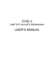
SXGA+ High Resolution LCOS Projector (ES50-116CM / ES70-116CM)
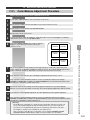
1
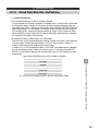
Before Service Work Begins
1.1.
What This Manual Covers
………………
1-2
1.2.
Related Materials
………………
1-2
1.3.
Special Items To Note When Performing Service
………………
1-3
1.4.
Tools Required
………………
1-4
1.5.
Lamps
………………
1-6
Maintenance
Part 1
2
~Component Replacement・
・Cleaning・
・Inspection・
・Troubleshooting~
Disassembly And Component Replacement Methods
2.1.
………………
2-2
2.1.1. ES50-116CM
………………
2-2
2.1.2. ES70-116CM
………………
2-2
………………
2-3
2.2.1. ES50-116CM
………………
2-3
2.2.2. ES70-116CM
………………
2-3
………………
2-4
2.3.1. ES50-116CM
………………
2-4
2.3.2. ES70-116CM
………………
2-4
………………
2-5
2.4.1. ES50-116CM
………………
2-5
2.4.2. ES70-116CM
………………
2-6
………………
2-7
2.5.1. Projection Unit Disassembly Diagram
………………
2-7
2.5.2. Component List
………………
2-8
………………
2-9
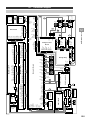
2.6.1. Board ASSY Main (Main Board)
………………
2-9
2.6.2. Optical Engine (Incl. LCOS Panel, Drive Board)
………………
2-14
2.6.3. Board ASSY SW (Switch Board)
………………
2-22
2.6.4. Board ASSY REM (Photoreceptor Board)
………………
2-23
2.6.5. Board ASSY CONNECT (Connector Board)
………………
2-24
2.6.6. Fan DC Motor (80) (Circuit Cooling FAN; F1)
………………
2-25
2.6.7. Circuit Power Block
………………
2-26
2.6.8. Fan DC Motor (Power Cooling FAN; F2)
………………
2-27
2.6.9. Circuit Power ASSY
………………
2-28
2.6.10. Board ASSY RL (Relay Board)
………………
2-29
2.6.11. Lamp Changer ASSY (Lamp Auto Changer)
………………
2-30
2.6.12. Board ASSY Changer Control (Changer Control Board) ………………
2-31
2.2.
2.3.
2.4.
2.5.
Removing The Rear Cover
Removing The Screen
Mirrors
Removing The Projection Unit
Projection Unit Disassembly
2.6. Projection Unit Components
Contents - i
SXGA+ High Resolution LCOS Projector (ES50-116CM / ES70-116CM)
2.6.13. Lamp Power ASSY (Lamp Power)
………………
2-32
2.6.14. Fan DC Motor (80) (Lamp FAN; F6, F7)
………………
2-33
2.6.15. Fan DC Motor (60) (PBS Cooling FAN; F3)
………………
2-34
2.6.16. Fan DC Motor (60) (LCOS Cooling FAN; F5)
………………
2-34
………………
2-35
2.7.1. Replacement Procedure
………………
2-35
2.7.2. Check Operating Time
………………
2-35
2.7.3. Lamp Replacement Operation
………………
2-36
2.7.4. Reset Operating Time
………………
2-38
………………
2-39
2.7. Lamp Replacement Method
2.8. List Of Adjustments On Unit Replacement Parts
3
4
5
Failure Assessment from Message Displays and LED Lamp
Displays
3.1.
Assessment From Message Displays
………………
3-2
3.2.
Assessment From Failure Assessment Lamp Beside Power ………………
On Button And Status Display Lamp On Main Board
3-4
Detailed Failure Assessment Methods (Detailed Troubleshooting)
Important-Must Read Before Starting Inspections
………………
4-2
4.1.
Failure Display Functions
………………
4-3
4.2.
List Of Failures
………………
4-6
4.3.
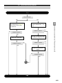
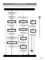
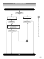
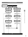
Failure Assessment Flowchart
………………
4-8
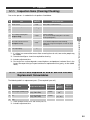
Inspection Methods (Cleaning, Parts Replacement)
5.1.
………………
5-2
5.1.1. Inspection Items (Cleaning/Checking)
………………
5-2
5.1.2. List Of Parts Replaced At End Of Service Life And
Replacement Consumables
………………
5-2
………………
5-3
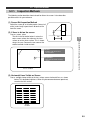
5.2.1. Inspection Methods
………………
5-3
5.2.2. Screen Inspection/Cleaning
………………
5-4
5.2.3. Mirror Inspection/Cleaning
………………
5-5
5.2.4. Projector Reflecting Mirror (Front Surface Mirror)
Cleaning Method
………………
5-6
5.2.5. Lens And Unit Lens Glass Cleaning Guidelines
………………
5-11
5.2.6. Lamp Changer Cleaning Guidelines
………………
5-14
5.2.7. Color Balance Checking And Adjustment Method
………………
5-14
5.2.
Inspections
Inspection Methods
Contents - ii
SXGA+ High Resolution LCOS Projector (ES50-116CM / ES70-116CM)
Part 2
6
Adjustments
Mechanical Adjustments – 6-Axis Adjustment and Mirror
Adjustment –
6.1.
Adjustment Specifications
………………
6-2
6.2.
Adjustment Procedure Overview
………………
6-3
6.3.
6-Axis Adjustment
………………
6-5
6.3.1. Preparation
………………
6-5
6.3.2. Detailed Adjustment Hardware Operating Method
………………
6-7
………………
6-9
6.4.1. ES50-116CM
………………
6-10
6.4.2. ES70-116CM
………………
6-11
6.4.
7
Adjusting The Mirror
Electrical Adjustments 1 – Adjustments Using Internal Signals
(Gamma Adjustment, Uniformity Adjustment) –
7.1.
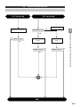
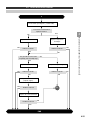
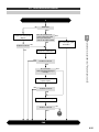
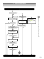
Adjustment Procedure Flowchart (Electrical Adjustments)
………………
7-2
7.2.
Adjustment Procedure Digest
………………
7-4
7.3.
Adjustment Procedure
………………
7-6
7.3.1. Adjustment Preparations
………………
7-6
7.3.2. Gamma Adjustment And Uniformity Adjustment Using
Internal Signals
………………
7-7
Multi-Screen Color Balance Adjustment
………………
7-13
7.4.1. Color Balance Adjustment Procedure
………………
7-13
………………
7-14
7.4.
7.5.
8
~ Screen Adjustments・
・System Adjustments ~
ID Remote Controller Operation Method
Electrical Adjustments 2 – External Signal Connection
Adjustments (Setup) –
8.1. External Signal Setup
………………
8-2
8.1.1. Setup And Mode Numbers
………………
8-2
8.1.2. Mode Number Automatic Search (Auto-Scan)
………………
8-4
8.1.3. Concerning Mode Numbers 134~191
………………
8-5
8.1.4. Mode Number Skipping
………………
8-6
8.1.5. Setup Data Selection And Setting
………………
8-7
8.1.6. Check Frequency Setting (SYNC SET)
………………
8-12
8.1.7. Sampling Clock Setting (SAMPLE CLOCK)
………………
8-13
8.1.8. Scaling Factor Setting (SCALING) And Position
Adjustment (POSITION)
………………
8-15
8.1.9. Cable Compensation Setting (CABLE COMP) And
………………
Image Sampling Phase Adjustment (SAMPLE PHASE)
8-19
Contents - iii
SXGA+ High Resolution LCOS Projector (ES50-116CM / ES70-116CM)
9
8.1.10. External Signal Brightness And Color Adjustment
(External Signal Level Setting)
………………
8-22
8.1.11. Display Condition Check, Other Settings
………………
8-25
8.1.12. Auto-Scan Settings
………………
8-29
8.1.13. Changing RGB Input Terminals And Copying Between
Mode Numbers
………………
8-32
8.2. Projector Adjustment Data Record Sheet
………………
8-34
8.3. Setup Data List
………………
8-38
………………
9-2
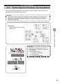
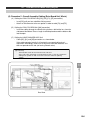
9.1.1. Control Single Projector Using RS232C Communication ………………
9-2
9.1.2. Control Multiple Projectors Using RS485 Communication ………………
9-4
9.1.3. Control Multiple Projectors Using RS232C
Communication
………………
9-7
………………
9-9
9.2.1. RS232C
………………
9-9
9.2.2. RS485
………………
9-9
………………
9-10
9.3.1. Overview
………………
9-10
9.3.2. Format
………………
9-10
………………
9-13
………………
10-2
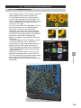
10.1.1. Characteristics
………………
10-2
10.1.2. External Appearance
………………
10-3
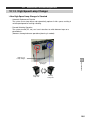
10.1.3. High-Speed Lamp Changer
………………
10-5
10.2. Ancillary Site Requirements For Installation
………………
10-6
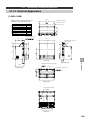
10.3. Maintenance Area Specification
………………
10-7
10.3.1. ES50-116CM
………………
10-7
10.3.2. ES70-116CM
………………
10-8
10.4. Connection Specification
………………
10-9
10.5. Accessories
……………… 10-10
10.6. Packaging
……………… 10-12
Projector System Setup and Control
9.1. Projector Control
9.2.Communication Specifications
9.3.Communication Procedure
9.4.Communication Commands
Part 3
10
Technical Data
Specifications
10.1. Characteristics And External Appearance
10.6.1. ES50-116CM
……………… 10-12
10.6.2. ES70-116CM
……………… 10-12
Contents - iv
SXGA+ High Resolution LCOS Projector (ES50-116CM / ES70-116CM)
10.7. Component Names And Functions
11
12
10.7.1. Rear Terminal Plate And Power Switch
……………… 10-13
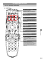
10.7.2. Remote Controller
……………… 10-16
Block Diagrams
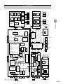
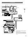
11.1. Circuit Block Diagram
………………
11-2
11.2. Protection Circuit System Diagram
………………
11-3
………………
12-2
………………
13-2
Block to Block Connection Diagram
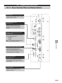
12.1. Connection Diagram
13
……………… 10-13
Cable Installation Diagram
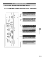
13.1. LCOS Multi-Screen Model Cabling Diagram
Appendix
A.
Adjust Menu Tree
……………… App.-1
B.
Adjustment Classification And Time Requirement
……………… App.-8
C.
Functions And Setting Items
……………… App.-13
D.
Other Check Items
……………… App.-18
E.
Theoretical Principle
……………… App.-19
F.
1.
LCD Panel Display
……………… App.-19
2.
Sampling Clock And Sampling Phase Adjustment
……………… App.-20
ES50-116CM/ES70-116CM Instruction Manual
……………… App.-21
Contents - v
1
Before Service Work Begins
1.1.
What This Manual Covers
1.2.
Related Materials
1.3.
Special Items To Note When Performing Service
1.4.
Tools Required
1.5.
Lamps
1-1
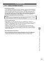
1.1.
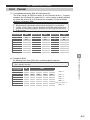
What This Manual Covers
This service technical manual covers the ES70-116CM and the ES50-116CM.
Unless explicitly stated, descriptions in this manual apply to both models.
1
Introduction
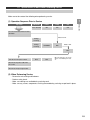
1.2.
Related Materials
Doc. No.
Document Name
Filename
152
Data Backup Software Operation Manual
(LCBACKUP)
Smd152-*.pdf
Remarks
[Asterisk (“*”) indicates revision number in filename.]
1-2
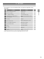
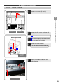
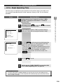
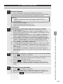
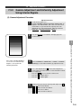
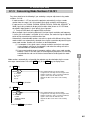
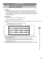
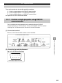
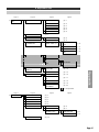
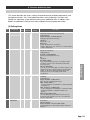
1.3.
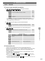
Special Items To Note When Performing Service
Make sure to take note of the following when performing service.
1
(1) Operation Sequence Prior to Service
LED Status
Power
Lamp
Fan
Green Flashing
ON
ON
ON
Introduction
Operation
Press the Remote Control or Power
On Button.
Orange
Flashing
Orange
Flashing
.
STAND BY
About 10 min.
OFF
About 1 min.
OFF
Turn off the main power switch.
OFF
OFF
When the lamp goes off, the fan
will also automatically turn itself
off.
Disconnect the power cable from
the socket.
Disconnect the input signal cable.
(2) When Performing Service
・
・
・
・
Restore the wire routing and tie downs.
Perform safety check.
Make sure nothing was omitted during servicing work.
Make sure any screws, components or wiring removed during servicing are put back in place.
1-3
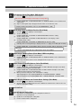
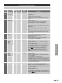
1.4.
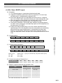
Tools Required
Tools required for service are listed below. Make sure to get them ready before starting
service work.
Tool Name
No.
Purpose
Philips screwdriver No. 2 point
Standard screws
2
Flat head screwdriver
Replace lamps
3
(+)Ratchet screwdriver
Use in spots with no space.
4
Ballpoint driver or hexagonal wrench
5mm, 2mm, 4mm
Operate six-axis mechanisms, remove
screens
5
Single head spanner, 7 mm, 13 mm width
(two tools)
Remove hardware used to secure for
transport.
6
Socket wrench and box screwdriver
10mm, 13mm, 17mm
Remove cabinet fasteners, screens
7
Lens or eyeglass cleaner tissue
Mirror and lens cleaning
8
Distilled or filtered water
Screen/mirror cleaning
9
Gauze
Screen/mirror cleaning
10
Air duster
Remove dust from mirrors and around the
LCOS panel
11
Personal computer (RS232C communication
capable)
Backup existing data, upgrade firmware
version
*1
1
Introduction
1
Notes
*1 : Needed in spots where there is no space. Recommend maximum 40 mm length.
Remote control and remote control cable are packaged with the interior accessories.
1-4
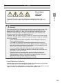
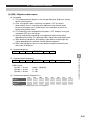
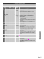
1.5.
Lamps
Shock Hazard
High Temp
Breakable
Introduction
When replacing lamps, check the model name of replacement lamps (sold
separately). Check the model name of replacement lamps against the repair parts
list.
1
Warning
The lamps used with this LCD projector are high pressure mercury glass lamps. High
pressure mercury lamps break with a loud noise from shock or damage, or from
deterioration after lengthy use. When they cease blinking it indicates that they are
about to fail. Different lamps have widely varying life spans, and sometimes they
break or cease blinking shortly after being put into use.
In addition, when the lamps break, glass shards can scatter into the lamp housing,
and gases, including mercury inside the lamp, can escape through the ventilation
holes of the projector.
・ Lamps sometimes break when subjected to shock or damage, or during use.
Please handle them carefully.
・ Using lamps for lengthy times beyond their replacement time increases the
chance they will break. When an instruction appears to replace a lamp, please
follow the instruction and replace the lamp promptly. Re-using old lamps (used
lamps) leads to breakage. Please do not do this.
・ In case a lamp does break (with a breaking sound), ventilate thoroughly,
vacuum up any gases emitted from projector ventilation holes, and make sure
nothing gets in your eyes or mouth.
・ Follow local ordinances and regulations regarding disposal of used lamps.
Generally they are classified along with other glass and glass bottles for
disposal purposes. However, some ordinances require separate sorting and
collection for lamps. Please be aware of this possibility.
・ Please do not use lamps with the lamp covers removed.
Lamp Replacement Indicators
Projector lamps have a finite usable lifetime. Images can become dark and discolored
with extended use. We recommend prompt replacement.
The lamp needs to be replaced when a “Lamp x Failure” or other lamp problem message
appears, or when the lamp indicator flashes red when the power is on.
1-5
2
Disassembly and Component Replacement Methods
2.1.
Removing The Rear Cover
2.2.
Removing The Screen
2.3.
Mirrors
2.4.
Removing The Projection Unit
2.5.
Projection Unit Disassembly
2.6.
Projection Unit Components
2.7.
Lamp Replacement Method
2.8.
List Of Adjustments On Unit Replacement Parts
2-1
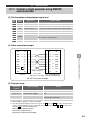
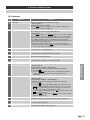
2.1.
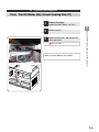
2.1. Removing The Rear Cover
2.1.1.
ES50-116CM
Lamp replacement hole.
1
Remove rear cover A.
Loosen 6 M4 screws and remove 2 M4
screws.
Loosen these.
Remove rear cover B.
Loosen the M4 screws at 2 spots on the
lower side and remove the M4 screws at
6 spots.
Remove these.
Rear cover (B)
2.1.2.
Rear cover (A)
Loosen these.
[Note]
Rear cover B is removed when:
(i) When taking out the projection unit.
(ii) When performing six-axis adjustment.
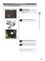
ES70-116CM
1
2
Disassembly Procedures and Component Replacement
2
Remove these.
Remove rear cover A.
Loosen 10 M4screws.
Loosen these screws.
2
Remove rear cover B.
Loosen the M4 screws at 2 spots on the
lower side and remove the M4 screws at 6
spots.
Loosen these.
3
Remove the screen covers (2 spots).
Loosen 2 M4 screws. Remove 1 M4
screw.
Loosen these.
Lamp replacement
panel
Remove these.
Remove these.
Rear cover (A)
Rear cover (B)
Screen removal cover
[Note]
Rear cover B is removed when:
(i) When taking out the projection unit.
(ii) When performing six-axis adjustment.
2-2
2.1.
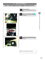
2.2. Removing The Screen
2.2.1.
ES50-116CM
First remove rear cover A as shown in
2.1.1.
2
Insert your hand through the rear surface
opening. Remove the screen fastener
bolts, two each on the left and right, with a
hex wrench (M5). Remove the screen
ASSY from the front.
Use maintenance tool M5 hex wrench.
3
Ball catch
Screen
Screen fastener bolts
(2 each L/R)
Push the screen frame forward from the
back and remove the screen from the
front.*2
Perform this operation with two people (1 in
front, 1 in back).
Work in reverse order to reassemble.
2.2.2.
ES70-116CM
1
2
Disassembly Procedures and Component Replacement
1
Remove rear cover A and the screen
covers (2 spots) as shown in 2.1.2.
Put your hand into the opening exposed
by removing the cover. Remove the
screen fastener bolts, 2 each right and
left, with a hex wrench (M5).
Use maintenance tool M5 hex
wrench.
3
Ball catch
Screen
Push the screen frame forward from the
back *1 and remove the screen from the
front.*2
Screen fastener bolts
(2 each L/R)
Perform this operation with two people (1 in
front, 1 in back).
Work in reverse order to reassemble.
[Warnings]
・When pushing out the screen, press the screen frame from the rear to keep from soiling or
damaging the screen surface.
・When removing the screen, pull it straight out in line with the ball catch.
2-3
2.1.
2.3. Removing The Mirror
2.3.1.
ES50-116CM
Remove the screen and rear cover, referring to 2.1.1 and 2.2.1.
2
Remove the 13 mirror adjustment screws from the rear surface and the upper mount.
3
Remove the M8 bolts, one each from left and right (total 2). You will need an operator
who can apply pressure while you remove the bolts so the mirror does not come out.
4
Tilt the mirror and pull it upward to remove.
M8 x 25mm (1 each L/R)
2.3.2.
2
Disassembly Procedures and Component Replacement
1
ES70-116CM
1
Remove the screen and rear cover, referring to 2.1.1 and 2.2.1.
2
Remove the 17 mirror adjustment screws from the rear surface and the upper level.
3
From the front of the mounting, remove the 14 screws, left and right, on the front of the
mirror. You will need an operator who can support the mirror while you remove the
screws so it does not fall out.
4
Two operators together lift the mirror from the front of the mounting to remove it.
M8 x 25mm (1 each L/R)
2-4
2.1.
2.4. Removing The Projection Unit
2.4.1.
ES50-116CM
1
Remove rear covers (A) and (B).
2
Rear Cover (A)
2
Remove two M4 screws each from left
and right.
Loosen these screws.
Handles (3 spots)
3
Remove the space filler hardware from
these two spots, left and right.
4
Remove the three M8 bolts.
5
Grip the unit handles and pull it out
toward the rear.
Disassembly Procedures and Component Replacement
Rear Cover (B)
13 mm ratchet wrench needed.
Space filler
hardware
M8 bolts (3)
2-5
2.1.
2.4.
2.4.2.
Removing The Projection Unit
ES70-116CM
1
Remove rear covers (A) and (B).
2
Rear Cover (A)
2
Remove two M4 screws each from left
and right.
Loosen these screws.
Handles (3 spots)
3
Remove the space filler hardware from
these two spots, left and right.
4
Remove the three M8 bolts.
5
Grip the unit handles and pull it out
toward the rear.
Disassembly Procedures and Component Replacement
Rear Cover (B)
13 mm ratchet wrench needed.
Space filler
hardware
M8 bolts (3)
2-6
2.1.
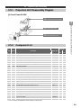
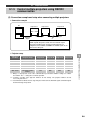
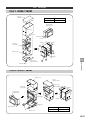
2.5. Disassembling The Projection Unit
2.5.1.
Projection Unit Disassembly Diagram
A projection unit disassembly diagram appears below. Follow the numerical sequence (1, 2,
3…) of adjustments indicated in the figure in 2.8. after replacing the various component parts.
After you finish with replacements and adjustments, make sure you update setting data on the
appended projector setting data sheet. This data will be used the next time the unit is serviced.
(1) Overall View
F Board ASSY REM (Remote signal)
□
Lens Cover
Lens Sheet
Top Cover
A Board ASSY Drive (Drive Board)
□
C Board ASSY Connect (Connector Board)
□
L Circuit Cooling Fan (F1)
□
2
Disassembly Procedures and Component Replacement
Lamp Cover
B Board ASSY Main (Main Board)
□
H0 Circuit Power Block
□
U Optical Engine (Incl. LCOS Panel)
□
M PBS Cooling Fan (F3)
□
N LCOS Cooling Fan (F5)
□
P Lamp ASSY
□
Q Lamp Changer ASSY
□
R Changer Control Board
□
G Lamp Power
□
J Lamp Fan (F6, F7)
□
Rear Cover (B)
E Board ASSY SW (Switch Board)
□
2-7
2.1.
2.5.
2.5.1.
Projection Unit Disassembly
Projection Unit Disassembly Diagram
(2) Circuit Power BLOCK
D Board ASSY RL (Relay Board)
□
2
K Power Cooling Fan (F2)
□
2.5.2.
Component List
No. Symbol
Item Name
Staff No.
Chart No. Model Model
50
70
(1)
A
Board ASSY Drive (Drive Board)
UX23721
1
1
(2)
B
Board ASSY Main (Main Board)
UX23711
1
1
(3)
E
Board ASSY SW (Switch Board)
*1
1
1
(4)
F
Board ASSY REM (Remote Control Photoreceptor Board)
*1
1
1
(5)
C
Board ASSY Connect (Connector Board)
*1
1
1
(6)
L
Fan DC Motor (80) (Circuit Cooling Fan; F1)
GS01021
1
1
(7)
H0
-
-
-
(8)
K
Fan DC Motor (60) (Power Cooling Fan; F2)
GS01011
1
1
UX23701
1
1
*1
1
1
Circuit Power Block
(9)
H
Circuit Power ASSY
(10)
D
Board ASSY RL (Relay Board)
(11)
Q
Lamp Changer ASSY (Lamp Auto Changer)
TS05781
1
1
(12)
R
Board ASSY Changer Control (Changer Control Board)
TS05791
1
1
(13)
G
Lamp Power ASSY (Lamp Power)
HA01461
2
2
(14)
J
Fan DC Motor (80) (lamp Fan; F6, F7)
GS01021
2
2
(15)
U
Optical Engine for 50” Model (Incl. LCOS Panel, Drive Board)
UX23731
1
-
(15)
U
Optical Engine for 70” Model (Incl. LCOS Panel, Drive Board)
UX23732
-
1
(16)
M
Fan DC Motor (60) (PBS Cooling Fan; F3)
GS01171
1
1
(17)
N
Fan DC Motor (80) (LCOS Cooling Fan; F5)
GS01161
1
1
-
P
Lamp ASSY
DT00681
2
2
-
-
Remote Control Transmitter Unit (RC-300)
HL01951
1
1
-
-
Cable (Remote Controller) 25M
2901793
1
1
-
-
Cable (Remote Controller) 3M
EW06011
-
-
-
-
50” Screen ASSY
UE23902
1
-
UE23872
-
1
70” Screen ASSY
*1 : Please arrange for P#UX23711 when making a new purchase.
Disassembly Procedures and Component Replacement
H Circuit Power ASSY
□
2-8
2.1.
2.6. Projection Unit Components
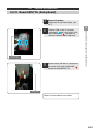
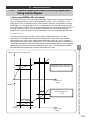
2.6.1.
Board ASSY Main (Main Board)
Listed below are the adjustments performed when the main board is replaced. (Some are
also required when other boards are replaced.)
Backup pre-replacement board adjustment data.
Adjust DIP switch settings, etc.
Replace main board
Transfer backup data to new board.
Uniformity *1 and gamma adjustments
*1 : Formerly referred to as “purity adjustment.”
(1) Backup Pre-Replacement Board Adjustment Data
All adjustment data is stored on the main board (except for certain data that relies on the
panel optical properties, which is stored in the drive board). Consequently, if the prereplacement main board adjustment data is transferred in its entirety to the postreplacement main board, it should be possible to restore settings to their previous state.
Main board data backup is performed using a PC.
Please refer to the “Data Backup Software Operations Manual” for detailed information
about the backup method.
【Warning】
If the main board error is fatal, and if data backup is not possible using the method described above,
please return the board to the manufacturer.
The manufacturer will repair the board, read off the adjustment data and communicate it to us.
2
Disassembly Procedures and Component Replacement
(1)
(2)
(3)
(4)
(5)
2-9
2.1.
2.6.
2.6.1.
Projection Unit Components
Board ASSY Main (Main Board)
(3) Main Board Replacement
1
Removal procedure
Remove 6 M4 screws.
These screws
Remove cables DF, EF, FF, and SS, and
then remove Board ASSY Main as shown
at left.
Work in reverse order to install a new board.
Before installing a new board, make sure to
set the DIP switches as indicated in the
following subsection.
Disassembly Procedures and Component Replacement
2
2
2-10
2.1.
2.6.
2.6.1.
Projection Unit Components
Board ASSY Main (Main Board)
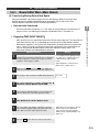
(4) DIP Switch, Etc., Settings
The following describes the setting functions performed by the DIP switches (S200) and
push switches (S130, S530) on the main board. Make sure the settings on the new board
are the same as for the board being replaced.
2
Disassembly Procedures and Component Replacement
8
1
ON
OFF
Push Switches
凹 ON 凸 OFF
DIP Switch
DIP Switch
No.
Setting Function
OFF (OPEN)
ON
1
Reset switch
Default
Reset
2
(Reserved)
-
-
3
Program initialization (clear) switch
OFF
Operates when main power is ON
4
(Reserved)
-
-
5
(Reserved)
-
-
OFF
Operates when main power is ON
6
*1
Adjustment data initialization (clear) switch
7
Troubleshooting
Default
Halts troubleshooting
8
(Reserved)
-
-
・ The default setting for all these switches is OFF.
*1: Set DIP switch (6) to the ON position and turn ON the main power. Main board ST1 and ST2 will
alternately flicker, and after about 10 seconds they will both flicker and then go off. Restore DIP switch
(6) to its original setting and transfer the data.
Note that repair parts are shipped with the adjustment data initialized (clear). Accordingly, there is no
need to check the data on repair parts before initializing.
Push Switch (S130)
)
No.
Setting Function
OFF
ON
1
RS-485 terminal setting
No terminal
Terminal available
・ Set to ON (terminal available) when RS-485 IN only or OUT only are attached.
・ Set to OFF (no terminal) when RS-485 IN/OUT are both connected.
・ Set to OFF (no terminal) when unused with no connection.
2-11
2.1.
2.6.
2.6.1.
Projection Unit Components
Board ASSY Main (Main Board)
(5) Transferring Backup Data to New Board
After the new board is physically installed, use the “data backup software” to transfer data
backed up from the swapped-out board onto the new board. Please refer to the “Data
Backup Software Operations Manual” for detailed procedures.
Data not to be transferred
Regarding 「ADC INPUT PRESET」
」
・ ADC Input Preset is the adjustment value for the AD converter input level. This adjustment is
main-board specific, and so is not backed up or transferred using data backup software.
・ Main boards supplied as service parts are shipped from the factory with pre-set adjustment
values. There is no need to readjust the values after replacement. You should rewrite the
value on the attached adjustment data sheet to the new board setting values. The
adjustment method is described below for reference.
Adjustment Content
1
Attach a signal source and input a signal in which black
(minimum level) and white (maximum level are displayed.
The input signal has a vertical sync frequency of 60 Hz
regardless of the display resolution.
Remarks
Use a high-precision signal generator
as signal source, making sure to use
it with the image output shown
below.
Signal amplitude : 0.700±0.002V
Black setup : 0.000±0.001V
2
While pressing ADJ, press the SUB key to display the
service person adjust menu. Set the mode number to “0."
3
If the image is dark, change the CLAMP POS adjustment.
4
Go to offset adjustment as follows: FACTORY ADJ. ADC INPUT PRESET INPUT OFFSET COM.
5
For each primary color display, start with the maximum
value and work downward. Do the various adjustments
when the black area of the input signal turns white.
6
Go to amplitude adjustment as follows: FACTORY
ADJ. ADC INPUT PRESET INPUT LEVEL.
7
For each primary color display, start with the minimum
value and work upward. Adjust at the points where the
100% white area of the input signal turns black.
8
Press the END key to close the service person menu.
2
Disassembly Procedures and Component Replacement
・ Do not transfer data indicated by “○” in the “Data not transferred by the maintenance PC”
column in the “List of Adjustment Categories and Needed Times” in Section 8-2.
See 9-4-3
Adjust when the area that has turned
black is largest. This adjustment
unifies the internal signal 240/255
with the image signal (normally 0.7V)
white area.
2-12
2.1.
2.6.
2.6.1.
Projection Unit Components
Board ASSY Main (Main Board)
(6) Gamma and Uniformity Adjustments
Display Position Modification
When performing uniformity adjustment, if there is a sizable disparity between the
marker and the modification point, change the uniformity initialization setting using the
following procedure.
While pressing the ADJ key, press the SUB key to display the service person
menu.
2
Go to uniformity initialization setting as follows: COMMON UNIFORMITY UNIFORMITY INITIAL
3
Press the CLEAR key twice to perform initial setting.
4
In the result from Step 3 above, if the origin point for the cross-shaped marker
does not line up with the on-screen arrow, align the two as follows.
・ While pressing the ADJ key, move the arrow to the right by pressing the
key.
・ While pressing the ADJ key, move the arrow to the left by pressing the
key.
Disassembly Procedures and Component Replacement
1
2
Pressing the arrow key without pressing the ADJ key moves the marker
itself. If you move the marker by mistake, redo Step 3.
5
Press the END on the remote controller.
Gamma and Uniformity Adjustment
Please refer to the discussion of uniformity and gamma adjustment methods in
Chapter 7 for specifics about the adjustments.
2-13
2.1.
2.6.
2.6.2.
Projection Unit Components
Optical Engine (Incl. LCOS Panel, Drive Board)
Drive Board
1
Remove 9 M4 screws and remove the
lamp cover and top cover.
locations
LAMP COVER
TOP COVER
3
Detach the AA cable from the
Photoreceptor Board.
4
Remove 4 M4 screws and remove the
lens cover and lens sheet.
2
Disassembly Procedures and Component Replacement
2
Removal Procedure
Remove rear covers (A) and (B) (see
2.1.1 and 2.1.2).
locations
5
AA cable
Remove 10 M4 screws and take off the
top cover.
locations
TOP COVER
Photoreceptor board
LENS COVER,
LENS SHEET
2-14
2.1.
2.6.
2.6.2.
Projection Unit Components
Optical Engine (Incl. LCOS Panel, Drive Board)
6
Slide the
area in the direction of the
arrow with both hands, and remove the
flex cables from three locations.
2
Flex cables
SS cable
7
Remove the SS and VS cables attached
to the drive board from the relay board.
8
Remove 7 M3 screws from the
locations and take out A PSA-LCOSDRIVE.
VS cable
Disassembly Procedures and Component Replacement
Removing flex cables
Attaching flex cable
Work in reverse order to reassemble.
【Warning】
- When attaching the flex cables, make sure you insert them securely, push them all the way in, and
slide the opening in the → direction. (In the end a white section will emerge, as shown in the flex
cable attachment photo).
- Flex cables and flex connectors are very delicate, and be careful not to exert unnecessary pressure
when attaching and removing them.
2-15
2.1.
2.6.
2.6.2.
Projection Unit Components
Optical Engine (Incl. LCOS Panel, Drive Board)
Optical Engine
1
2
Remove 4 M4 screws and remove the lens
cover and lens sheet.
3
Remove 10 M4 screws and take off the
top cover.
LENS SHEET
2
Disassembly Procedures and Component Replacement
LENS COVER
Removal Procedure
Remove rear cover (B). (see 2.1.1.、
2.1.2.)
locations
TOP COVER
4
Remove 2 M4 screws
locations
2-16
2.1.
2.6.
2.6.2.
Projection Unit Components
Optical Engine (Incl. LCOS Panel, Drive Board)
5
Remove the SS and VS cables attached
to the drive board, along with F3 and F5
attached to the base.
2
Board ASSYdrive (drive board)
6
Gently slide the optical engine
alongside the main board and lift it up
when the gab moves clear.
Disassembly Procedures and Component Replacement
SS, VS, F3, F5
Work in reverse order to reassemble.
2-17
2.1.
2.6.
2.6.2.
Projection Unit Components
Optical Engine (Incl. LCOS Panel, Drive Board)
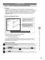
The following adjustments are performed when replacing the optical engine.
(2) 6-axis adjustment: repeat adjustment
(3) Copy VT gamma data
(4) LCOS control adjustment
(5) Contrast adjustment
(6) Uniformity adjustment, gamma adjustment (check)
Perform this adjustment as described in Chapter 6 “6-Axis Adjustment and Mirror Adjustment,”
after referring to “Panel Position” under (3) LCOS Control Adjustment, described below.
(2) Copy VT Gamma Data
VT gamma data is dependent on the optical properties of the specific LCOS panel. When
the optical engine is replace the panel is also replaced, so the data has to be rewritten to
the new panel. VT gamma data normally uses data stored on the main board. The
manufacturer adjusts VT gamma data to the specific panel properties and stores this data
on the drive board. After replacing the optical engine, this drive board data is copied to the
main board for use.
Adjustment Preparations
Set the scan mode to “0.”
【Warning】
If auto-scan and projector control are activated, use “Mode Change” to change the scan mode number.
Disassembly Procedures and Component Replacement
(1) 6-Axis Adjustment
2
MOVE GAMMA DATA Adjustment
1
While pressing the ADJ key, press the SUB key to display the service person
adjustment menu. Go to the copy screen as follows: FACTORY ADJ. MOVE
VT GAMMA DATA.
※When entering the copy screen, hold down the for 1-2 seconds.
2
Since this function is disabled by default, press the F1 key to enable it.
3
The message “PLEASE PUSH RIGHT KEY” is displayed.
4
Press the key.
5
The word “SAVE” will flash.
6
When the word “COMPLETED” is displayed VT GAMMA data copying is complete.
7
Check gamma adjustment in reference to “7.3.2 Gamma Adjustment and
Uniformity Adjustment Using Internal Signals”
2-18
2.1.
2.6.
2.6.2.
Projection Unit Components
Optical Engine (Incl. LCOS Panel, Drive Board)
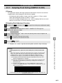
(3) LCOS Control Adjustment
Sets the control output voltage for the LCOS Panel on the drive board.
Adjustment Preparations
Set the scan mode to “0.” Input a PC signal to use for adjustment, and display a
window on screen. Use a vertical sync frequency of 60 Hz regardless of the
resolution.
GHOST Adjustment
While pressing the ADJ key, press the SUB key to display the service person
adjustment menu. Go to ghost adjustment as follows: FACTORY ADJ. LCOS
CONTROL GHOST.
2
Choose color “G” using the adjustment color select key. Turn colors “R” and “B” OFF
with the display color select key to yield a single-color “G” color display.
On the single-color “G” color screen, increase the “LR-FINE” value, and look at
the on-screen display for the value at which ghosting occurs on the right side.
Go back 2 from this and set this value. Make sure at this point that there is no
ghosting on the left side of the display.
【Key Operations】
Fine Adjust (LR-FINE):
(Normally this is enough to adjust)
Coarse Adjust (UD-COARSE):
(Change by ±1 when fine adjust is
not enough to adjust)
3
Disassembly Procedures and Component Replacement
【Warning】
If auto-scan and projector control are activated, use “Mode Change” to change the scan mode
number.
2
【Ex.】When faint ghosting occurs at a value of “7,” adjust it to “5.”
UD-COARSE
“4”
LR-FINE
“5”
“4”
“6”
Ghost
Adjusted
value
None
“4”
“7”
“4”
“8”
Faint
Present
【Warning】 Look closely to see whether faint ghosting occurs at the sides of the
screen.
4
Adjust “R” and “B” in the same manner as above.
5
Adjustments complete. Press the END key to close the service person
adjustment menu.
FLICKER Adjustment
Flicker is adjusted with an automatic adjuster, and so does not need to be adjusted
with the remote controller.
2-19
2.1.
2.6.
2.6.2.
Projection Unit Components
Optical Engine (Incl. LCOS Panel, Drive Board)
CONVERGENCE Adjustment
Adjust the divergence of colors R and B in relation to G. Display the internal signal patch
pattern to check the divergence, and if noted, adjust it through the following procedure.
1
Choose FACTORY ADJ. LCOS CONTROL CONVERGENCE in the
service person adjustment menu.
2
Choose the color being adjusted.
3
Use the keys to adjust for minimum divergence in relation to color
G.
2
Adjustment item (1) presumes that 6-axis adjustment has been completed, so this
adjustment is essentially unnecessary. However, you may need to make the
adjustment if you have to adjust for positional deviation of about 1 pixel in the seams
between screens.
1
Choose COMMON XY POSITION in the service person adjustment menu.
2
Press the CLEAR key on the remote controller twice to clear the data.
3
Choose FACTORY ADJ. LCOS CONTROL PANEL POS.
4
Use the keys to modify the patch position. (see below)
Adj. Value
OK
Disassembly Procedures and Component Replacement
PANEL POS. Adjustment (XY POSITION Adjustment)
)
Outermost line not displayed.
NG
2-20
2.1.
2.6.
2.6.2.
Projection Unit Components
Optical Engine (Incl. LCOS Panel, Drive Board)
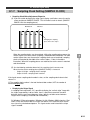
PHASES BALANCE Adjustment (8-Phase Adjustment)
)
Bright vertical stripe 8
pixels wide.
Choose 8-phase adjustment as follows:
FACTORY ADJ. LCOS CONTROL PHASES BALANCE.
2
Display the internal grayscale screen and
set it to single-color display of R, G, or B.
Check in this condition to see if an 8-pixel
wide vertical stripe is generated.
If a stripe appears = unevenness in the
brightness, go onto the next step.
3
Choose the color being adjusted (same
as color displayed) and display the
adjustment marker (operation detailed
below).
Dark vertical stripe 8
pixels wide.
Adjustment
marker
・Display marker: ・Move marker: ・Change marker brightness:F1 key
4
2
Disassembly Procedures and Component Replacement
1
Adjust the brightness uniformly so
that vertical stripes (phases) aligned
with the adjustment marker
disappear.
・Brighten stripe: ADJ + ・Darken stripe:
ADJ + Notes:
1) The adjustment marker automatically
flickers.
2) Changing the brightness adjustment
value or the adjustment color causes
the marker to disappear.
SHARPNESS Adjustment
Used with the default value, so no adjustment is needed.
(4) DRIVE COM. Adjustment
Visually confirm and adjust as needed, referring to “7.3.2. Gamma Adjustment and
Uniformity Adjustment Using Internal Signals.”
(5) Uniformity Adjustment and Gamma Adjustment (Check)
Visually confirm and adjust as needed, referring to “7.3.2. Gamma Adjustment and
Uniformity Adjustment Using Internal Signals.”
2-21
2.1.
2.6.
Projection Unit Components
2.6.3. Board ASSY SW (Switch Board)
1
Removal Procedure
Remove 2 M4 screws.
these screws
Remove 2 M3 screws from the DD cable.
these screws
3
Disassembly Procedures and Component Replacement
2
2
Remove the Board ASSY SW as shown
in the illustration.
Work in reverse order to reassemble.
2-22
2.1.
2.6.
Projection Unit Components
2.6.4. Board ASSY REM (Photoreceptor Board)
Removal Procedure
Remove rear cover (B). (see 2.1.1.,
2.1.2)
2
Remove 2 M3 screws and the AA cable,
and remove the Board ASSY REM.
these screws
Work in reverse order to reassemble.
2
Disassembly Procedures and Component Replacement
1
2-23
2.1.
2.6.
Projection Unit Components
2.6.5. Board ASSY Connect (Connector Board)
1
Removal Procedure
Remove rear cover (B). (see 2.1.1.、
2.1.2)
Remove the Switch Board. (see 2.6.3.)
3
Remove the Main Board. (see 2.6.1.)
4
Detach the following cables connected to
the connector board.
HA, CA, EF, FF, DF, VX, VS, VY, IT, IG,
GV, BV, HD, IH, F1, F2, F3, F4, F5, F6,
F7, F8, PA, EH, DD, AA
Total cables detached: 26
5
Remove 4 M3 screws and remove the
connector board.
Disassembly Procedures and Component Replacement
2
2
these locations
Work in reverse order to reassemble.
2-24
2.1.
2.6.
Projection Unit Components
2.6.6. Fan DC Motor (80) (Circuit Cooling Fan; F1)
Removal Procedure
Remove the Main Board. (see 2.6.1.)
2
Remove cable F1.
3
Remove 2 M4 screws, and take out the
circuit cooling fan.
these screws
Work in reverse order to reassemble.
2
Disassembly Procedures and Component Replacement
1
2-25
2.1.
2.6.
Projection Unit Components
2.6.7. Circuit Power Block
1
Removal Procedure
Remove 5 M4 screws.
these screws
Remove the Circuit Power Block.
3
Remove the two bead band fasteners.
4
Remove cables EH, PA, VI, F8, and F2.
Disassembly Procedures and Component Replacement
2
2
Work in reverse order to reassemble.
2-26
2.1.
2.6.
Projection Unit Components
2.6.8. Fan DC Motor (Power Supply Cooling Fan; F2)
Removal Procedure
Remove the circuit power BLOCK. (see
2.6.7.)
2
Remove 1 M3 screw in this spot
,
and remove two bead band fasteners in
this spot
.
3
Detach the power supply from the base
hardware and remove the Power Supply
Cooling Fan.
2
Disassembly Procedures and Component Replacement
1
Work in reverse order to reassemble.
2-27
2.1.
2.6.
Projection Unit Components
2.6.9. Circuit Power ASSY
1
Remove five clips from the spots marked
in
and remove the Circuit Power
ASSY.
2
Disassembly Procedures and Component Replacement
2
Removal Procedure
Remove the circuit power BLOCK, the
relay board fastener hardware, and the
power supply cooling fan (see 2.6.7.,
2.6.8., 2.6.10)
Work in reverse order to reassemble.
2-28
2.1.
2.6.
Projection Unit Components
2.6.10. Board ASSY RL (Relay Board)
1
Removal Procedure
Remove the Circuit Power Block. (see
2.6.7)
3
Remove cables VB and VI, and remove 2
M3 screws at the spots marked with
.
Remove the Board ASSY RL.
Relay board
fastener hardware
2
Disassembly Procedures and Component Replacement
2
Remove 2 M4 screws in the spots
marked with
and 3 m3 screws in the
spots marked with
. Remove the
fastener hardware and the top cover.
Relay board
Work in reverse order to reassemble.
2-29
2.1.
2.6.
Projection Unit Components
2.6.11. Lamp Changer ASSY (Lamp Auto Changer)
1
Removal Procedure.
Remove rear cover (B) (see 2.1.1., 2.1.2.)
Remove 2 M4 screws at the spot marked
by
.
3
Remove the bead band fasteners and
wire clamps fro the spots marked
by
.
4
Remove cables HD, IH, and VB.
5
Slide the Lamp Changer ASSY in
direction a (forward).
6
Move the Lamp Changer ASSY in
direction b (laterally) and detach it from
the positioning pin.
7
Pull out the Lamp Changer ASSY in
direction c (forward).
8
Reattachment Procedure.
Work in reverse order to reassemble.
Make sure when reattaching that the
three positioning pins marked in fit
securely in the three holes on the side of
the changer.
M4 screws
Bead bands
Wire clamps
b
a
c
2
Disassembly Procedures and Component Replacement
2
Positioning pin
2-30
2.1.
2.6.
Projection Unit Components
2.6.12. Board ASSY Changer Control
(Changer Control Board)
1
Detach cables HD, IT, IG, F7, F6, BV,
GV, VB, VG, KC, KA, VJ, and IH.
Total cables detached: 13
3
Remove 1 M3 screw at the indicated
location.
4
Disengage four latches at the
indicated locations and take out the
Changer Control Board.
2
Disassembly Procedures and Component Replacement
2
Removal Procedure
Remove the Lamp Changer ASSY (see
2.6.11).
Work in reverse order to reassemble.
Latches
M3 screws
2-31
2.1.
2.6.
Projection Unit Components
2.6.13. Lamp Power ASSY (Lamp Power)
Removal Procedure
Remove the Lamp Changer ASSY. (see
2.6.11)
2
Detach 3 clamps and 2 side hooks, and
remove the power cover that covers the
lamp power supply.
Clamps
Power cover
Clamp
Power cover
3
4
Power cover
2
Disassembly Procedures and Component Replacement
1
Detach cables VG and GV from lamp
power 1 and cables VB and BV from
lamp power 2.
Remove 4 M3 screws and take out the
lamp power units, releasing the four
latches in sequence.
Lamp changer base
5
Lamp power 1 for lamp 1 (screen side) is
located on the side of the Lamp Changer
ASSY.
Lamp power 2 for lamp 2 (rear side) is
located below the Lamp Changer ASSY.
Work in reverse order to reassemble.
【Warning】
When reattaching the power cover, make sure to reattach the power cover hook to the cover hole.
2-32
2.1.
2.6.
Projection Unit Components
2.6.14. Fan DC Motor (80) (Lamp FAN ; F6, F7)
Removal Procedure
Remove the Lamp Changer ASSY. (see
2.6.11)
2
Detach cable F7 in the case of lamp 1
fan, and cable F6 in the case of lamp 2
fan.
3
Remove 2 M3 screws and take out the
lamp fan.
Work in reverse order to reassemble.
2
Disassembly Procedures and Component Replacement
1
2-33
2.1.
2.6.
Projection Unit Components
2.6.15. Fan DC Motor (60) (PBS Cooling FAN; F3)
LCOS Cooling FAN
Removal Procedure
Remove the optical engine. (see 2.6.2)
2
Detach cable F3 from the back side of
the Optical Engine.
3
Remove 2 M4 screws and remove the
PBS Cooling Fan.
Work in reverse order to reassemble.
2
Disassembly Procedures and Component Replacement
PBS Cooling FAN
1
2.6.16. Fan DC Motor (60) (LCOS Cooling FAN; F5)
PBS Cooling FAN
LCOS Cooling FAN
1
Removal Procedure
Remove the Optical Engine. (see 2.6.2)
2
Detach cable F5 from the back side of
the optical engine.
3
Remove 2 M4 screws and take out the
LCOS Cooling Fan.
Work in reverse order to reassemble.
【Warning】
Make sure you don’t forget to reattach
the fan duct.
2-34
2.1.
2.7. Lamp Replacement Method
2.7.1.
Replacement Procedure
Replace the lamp using the following procedure.
(1) Check operating time: check the cumulative operating time for the lamp being replaced.
(2) Lamp replacement: take out the old lamp and put in a new lamp.
(3) Clear operating time: clear out the old pre-replacement data.
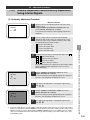
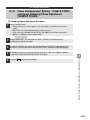
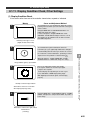
2.7.2.
Check Operating Time
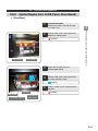
UNIT
LAMP1
TOTAL
CONTINUOUS
P-ON
COUNT
LAMP2
TOTAL
CONTINUOUS
P-ON
COUNT
Shows projector main unit operating time.
: 512h
: 12h
: 101
Indicates no. of flashes.
Shows time for lamp 2.
: 500h
: --h
: 100
Indicates no. of flashes.
:5000h
Shows time for lamp 1.
Cumulative operating time
Continuous flashing time
Cumulative operating time
“--” indicates lamp is not illuminated.
Disassembly Procedures and Component Replacement
(1) On-Screen Display
2
※ Non-illuminated lamp displayed in gray.
When Lamp Failure Occurs
LAMP2
: FAILURE
Indicates a failure has occurred in lamp 2.
Displayed in red in this case.
(2) Operating Procedure
(A) “USER” Mode
1
Press the TIMER key on the remote controller.
Projector main unit and lamp cumulative operating time, continuous flashing time and no. of
flashes are displayed on screen.
2
Press the TIMER key on the remote controller to end.
(B) “SERVICE” Mode
1
Press the F1 key on the remote controller while depressing the ADJ key.
Projector main unit and lamp cumulative operating time, continuous flashing time and no. of
flashes are displayed on screen.
2
Press the END key on the remote controller to end.
2-35
2.1.
2.7.
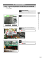
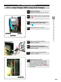
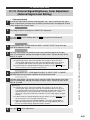
2.7.3.
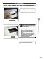
Lamp Replacement Method
Lamp Replacement Operation
(1) Advance Preparation
【Warnings】
・ Make sure to tighten screws securely. Loose screws can cause failure.
・ The lamp screws are flat-head screws.
・ The side lamp on the lamp changer flashes during lamp replacement.
Make sure not to touch it inadvertently.
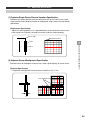
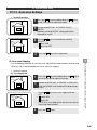
(2) Lamp Replacement Procedure
1
Loosen the indicated screws
to remove the rear cover.
2
Disassembly Procedures and Component Replacement
Take out the old lamp using the following procedure, and put in a new lamp with the same
procedure in reverse.
Check the operating time for the lamp being replaced with the lamp operating time
confirmation method described in the preceding subsection.
If neither lamp will illuminate, then replace both lamps. However, if you brought only one
lamp, then replace lamp 1 first. The projector will choose lamp 1 first to illuminate.
Lamp replacement
Window
Lamp replacement Window
(can be removed and replaced using magnet)
ES50-116CM
ES70-116CM
2-36
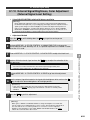
2.1.
2.7.
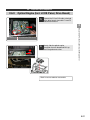
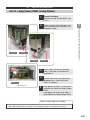
2.7.3.
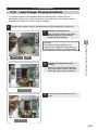
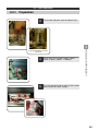
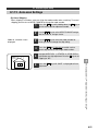
2
Lamp Replacement Method
Lamp Replacement Operation
Remove the 4 lamp cover screws (circled in red) and take off the lamp cover. The
screen side lamp is lamp 1, and the rear side (terminal side) lamp is lamp 2.
2
Disassembly Procedures and Component Replacement
Lamp 1
Lamp 2
Remove the three flat-head screws in the photograph below (circled in red),
grasp the handle, and take out the lamp.
3
Lamp
Handle
2-37
2.1.
2.7.
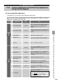
Lamp Replacement Method
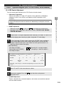
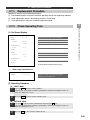
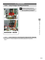
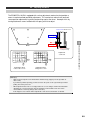
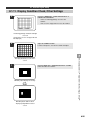
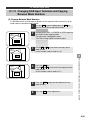
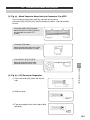
2.7.4. Reset Operating Time
After the lamps are replaced using the procedure on the previous page, you need to reset
the cumulative lamp operating time stored in projector memory to zero. Use the following
procedure.
Screen
Operating Method
2
While depressing the ADJ key, press the SUB key to display
the service person adjustment menu.
3
Go [LOG DATA] [LAMP1 TIME] or [LAMP2 TIME] to
choose one. Select the the lamp you checked in Step 1.
4
Press the CLEAR key twice to reset cumulative operating
time and no. of flashes to “0.” At this point the message
“LAMPx FAILURE” displayed in red will go off.
※You can also reset cumulative operating time to “0” by
pressing the key, but the system cannot tell from this
that lamp replacement is complete, and ”LAMPx
FAILURE” will not go off. You still have to press the
CLEAR key twice.
5
Press the END key to end.
LAMPx TIME
___h__min__s
P-ON OUNT : ____
LAMPx FAILURE
LAMPx TIME
0 h 0min 0s
P-ON COUNT:
0
6
2
Disassembly Procedures and Component Replacement
1
Confirm that the lamp is inoperative and that “LAMPx
FAILURE” is displayed as described in “2.7.2 Check
Operating Time.”
Confirm that the “LAMPx FAILURE” message described
in “2.7.2 Check Operating Time” has gone off.
【Warning】
You must confirm that the ”LAMPx FAILURE” message has gone off. If it is still showing, then the
alternating illumination feature and the lamp failure time automatic lamp replacement feature will not
work, even with a new lamp.
2-38
Board ASSY Drive (Drive Board)
Board ASSY Main (Main Board)
Board ASSY SW (Switch Board)
Board ASSY REM (Remote Control Photoreceptor
Board)
Board ASSY Connect (Connector Board)
Fan DC motor (80) (Circuit Cooling Fan; F1)
Board ASSY RL (Relay Board)
Fan DC motor (60) (Power Cooling Fan; F2)
Circuit power ASSY
Lamp changer ASSY (Lamp Auto Changer)
Board ASSY Changer Control (Changer Control
Board)
Lamp power ASSY (Lamp Power)
Fan DC motor (80) (Lamp Fan; F6, F7)
A
B
E
F
C
L
D
K
H
Q
R
G
J
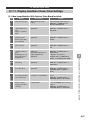
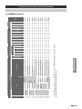
Replacement Part Name
Follow procedure in 2.6.2.
Follow procedure in 2.6.2.
(Maladjustment not supposed
to occur, but check the screen
and if needed, perform
adjustment)
(1) 6-axis adjustment
(2) Uniformity adjustment
(3) Gamma adjustment
(4) Color balance adjustment
(with multi-screen)
6-Axis adjustment
(1) 6-axis adjustment
(2) Uniformity adjustment
(3) Gamma adjustment
(4) Color balance adjustment
(with multi-screen)
6-Axis adjustment
Adjustment
Chapter 2
Assembly
/Disassembly
Described in
(1)
(1)
Repeat
Loop
(2)
(3)
(4)
(2)
(3)
(4)
Single
Hex Wrench
(5mm, 2mm),
RC-300
RC-300
Tools
1
2
1
2
1
2
1
1
1
1
1
1
1
Staff
15
20
10
5
15
10
15
10
10
10
5
5
10
Assemble
/Disassemble
10
30
10
30
10
5
5
5
5
5
5
30
30
Adjustment
Standard Time Required (Min)
Required Tools/Staff/Methods
---
6.3,
7.2,
7.3.2,
7.4.1
---
6.3,
7.2,
7.3.2,
7.4.1
---
---
---
---
---
---
---
2.6.1.
2.6.2.
Adjustment
Sequence
Described In
2.8.
Disassembly Procedures and Component Replacement
Symbol
2.1.
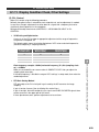
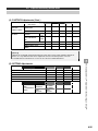
List Of Adjustments On Unit Replacement Parts
2
No need to un-stack unit in any instance.
2-39
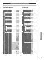
(1) 6-axis adjustment
(2) Uniformity adjustment
(3) Gamma adjustment
(4) Color balance adjustment
(with multi-screen)
Fan DC Motor (80) (LCOS Cooling Fan; F5)
Lamp ASSY
N
P
(Maladjustment not supposed
to occur, but check the screen
and if needed, perform
adjustment)
Chapter 2
Fan DC Motor (60) (PBS Cooling Fan; F3)
M
Follow procedure in 2.6.2.
Optical Engine for 70” mode
(includes LCOS Panel, Drive Board)
U
Follow procedure in 2.6.2.
Chapter 2, 7
Adjustment
Optical Engine for 50” Model
(includes LCOS Panel, Drive Board)
Assembly
/Disassembly
Described in
U
Replacement Part Name
(1)
Repeat
Loop
(2)
(3)
(4)
Single
Hex Wrench
(5mm, 2mm),
RC-300
Hex Wrench
(5mm, 2mm),
RC-300
Tools
1
1
1
2
2
Staff
5
15
15
10
10
Assemble
/Disassemble
30
10
10
60
60
Adjustment
Standard Time Required (Min)
Required Tools/Staff/Methods
6.3,
7.2,
7.3.2,
7.4.1
---
---
2.6.1.
2.6.2.
Adjustment
Sequence
Described In
2.8.
Disassembly Procedures and Component Replacement
Symbol
2.1.
List Of Adjustments On Unit Replacement Parts
2
No need to un-stack unit in any instance.
2-40
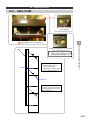
3
Failure Assessment from Message Displays and LED
Lamp Displays
3.1.
Assessment from Message Displays
3.2.
Assessment from Failure Assessment Lamp Beside Power
On Button and Status Display Lamp on Main Board
3-1
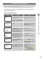
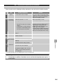
3.1. Assessment from Message Displays
Failure assessment is performed in accordance with Chapter 4 Detailed Failure Assessment
Methods. This chapter summarizes content likely to come up in customer inquiries, etc.
The projector displays the following messages based on set status. Respond as indicated
when these messages appear.
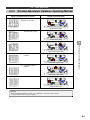
(1) Messages About the Lamps
Message
PLEASE REPLACE LAMP2
LAMP1 TIME ____h
LAMP2 TIME ____h
LAMP CHANGE
IN A MINUTE
LAMP1 TIME 1234h
LAMP2 FAILURE
POWER OFF
AFTER 0h__min
CONTINUOUS
LAMP1 TIME ____h
LAMP2 TIME ------h
CONTINUOUS
LAMP1 TIME 25h
LAMP2 FAILURE
One lamp has failed (Lamp 2, in this
example).
Replace the lamp and reset lamp
operating time to zero. Example display
indicated Lamp 2.
[LOG DATA] [LAMPxx TIME]
Indicates changer will automatically
Replace the lamp and reset lamp
replace lamp in 15 seconds when lamp operating time to zero.
forced-off is set to ON.
Forced-off time duration is set by menu. [LOG DATA] [LAMPxx TIME]
[FACTORY] [OTHERS]
[COMPULSORY SHUT-DOWN]
A failure has occurred in one lamp
Replace both lamps and reset lamp
when lamp forced-off is set to ON.
operating time to zero.
Forced-off will occur in 15 minutes.
Forced-off time duration is set by menu. [LOG DATA] [LAMPxx TIME]
[FACTORY] [OTHERS] [COMPULSORY SHUT-DOWN]
Failure Assessment from Message Displays and LED Lamp Displays
Displayed at startup when the lamp with No current failure condition exists, but
the longest cumulative operating time
lamp is nearing the end of its usable
exceeds 6,000 hours.
lifespan.
Displays approximately the last 100
hours of forced-off time when lamp
forced-off is set to ON. Displayed every
10 hours.
LAMP1 TIME 1234h
LAMP2 FAILURE
3
Response
and LED Lamp Displays
LAMP1 TIME ____h
LAMP2 TIME ____h
Description
The continuous illumination time for one Continuous illumination of over 24
lamp has exceeded 25 hours.
hours is not permitted. Enable the auto
This message will be redisplayed every lamp change function.
10 hours thereafter.
[SETTINGS] [LAMP SETTING] [AUTO CHANGE SEL.]
The continuous illumination time for one Replace the lamp and reset lamp
lamp has exceeded 25 hours, and a
operating time to zero.
failure has occurred in the other lamp.
[LOG DATA] [LAMPxx TIME]
This message will be redisplayed every (1) Enable the auto lamp change
10 hours thereafter.
function, similarly as described
above. However, when auto lamp
change is being activated by
external control via a telecom link,
the above menu setting is “OFF.”
3-2
3.1.
Assessment from Message Displays
(2) Input Signal Messages
Message
NO SIGNAL
LAMP CHANGE
IN A MINUTE
Displayed when no sync signal is input,
or a very high or low sync signal is
input.
Check whether the projector is correctly
outputting a signal. Also check the
cable connections.
If you still find nothing wrong, it is
possible there is a problem with the
main board.
Sync signal is being input, but cannot
be displayed with the preset data in the
projector.
Check the specs for the projector signal
output frequency, and change the
projector settings to within a frequency
range (screen resolution) the projector
can handle.
Displayed only when mode number is
being specified via external control.
Displayed when the signal adjusted
according to the specified mode
number differs from the current input
signal.
(1) First make sure there is no change
in the customer’s connected
equipment. If not, re-enter into
memory the frequency data for each
mode.
[MODE INITIAL SETUP] [SYNC SET]
(2) If an equipment change has
occurred (change in the PC, etc.,
resolution setting or the refresh
rate), restore the original settings.
(3) Failure Detection Messages
Message
FAN FAILURE
F1
ABNORMAL TEMPERATURE
Description
3
Failure Assessment from Message Displays and LED Lamp Displays
LAMP1 TIME ____h
LAMP2 TIME ____h
Response
and LED Lamp Displays
SYNC IS OUT OF RANGE
Description
Response
Displayed when the fan has stopped.
Failure condition assessed after one
minute of continuous stoppage, and
power turned OFF.
Restart by turning the main power from
OFF to ON. Check the fan number for
the failed fan and replace it. If the
image does not reappear, refer to
Chapter 4 and check against log data.
[LOG DATA] [RAS]
Displayed when a temperature sensor
near the lamp is activated and
assesses a failure condition. Power is
turned OFF.
Remove any blockage interfering with
exhaust from the lamp cooling fan. If no
blockage is found, refer to Chapter 4
and respond appropriately.
3-3
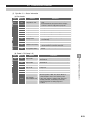
3.2.
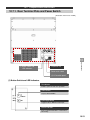
LED Lamp Display
Illuminated or flashing LEDs indicate projector status. These include a failure assessment
indicator beside the power button and a status LED on the main board.
No
Name
1 Power Lamp
(ON/STAND BY)
LED Status
Orange on
Description
Response (Example)
Wait state (stand by) with lamp off, power Normal
can be turned on by remote controller or
ON/STANDBY switch.
3
Green flashing Lamp on wait state or lamp restart
process in progress
Orange
flashing
Cooling process in progress (about 1
minute) after power OFF (lamp off).
Power cannot be turned ON while cooling
in progress.
Red flashing
Failure condition, power OFF.
Assess the failure
condition based on “Failed
Lamp” below.
On
ON/STAND BY flashing red
simultaneously.
Anomaly in both lamps.
Replace the lamp.
・
ON/STAND BY flashing green
simultaneously (lamp on).
Anomaly in one lamp.
Replace the lamp.
・Flashing
Lamp ASSY not mounted.
Securely mount the lamp.
・
ST2 on main board simultaneously on.
Anomaly in changer operation.
Replace the lamp changer.
・On
Temperature anomaly.
Check to make sure there
is no problem with fan
exhaust.
・
ST1 on main board simultaneously on.
Voltage anomaly on drive board.
Replace the power unit and
drive board.
・Flashing
Anomaly in fan operation.
Replace fan.
3 Main Board Status Green on
Lamp
Off or
(CPU)
flashing
Control CPU operating normally.
Normal
Anomaly in control CPU operation.
Replace main board and
power unit.
(ST1)
Red on
Indicates the nature of the failure in
combination with the failure assessment
lamp.
See section on TEMP for
failure assessment lamp.
(ST2)
Red on
ON/STAND BY flashing red
simultaneously.
Defect in changer operation.
Replace the lamp
changer.
Failure Assessment from Message Displays and LED Lamp Displays
(TEMP)
Lamp on
and LED Lamp Displays
2 Failed Lamp
(LAMP)
Green on
ON/STAND BY flashing green
simultaneously (lamp on).
Communication defect between
changers.
(TERM)
Green on
485 terminal setting time.
Normal
(TTL)
Green on
TTL terminal time
Normal
3-4
4
Detailed Failure Assessment Methods (Detailed
Troubleshooting)
Important
4.1.
Failure Display Functions
4.2.
List of Failures
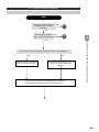
4.3.
Failure Assessment Flowchart
4-1
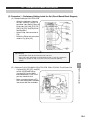
Important
Must Read Before Starting Inspections
* When installing the optional video board, refer to the List of Failures and the Video
Board Installation List of Failures.
4
Detailed Failure Assessment Methods ((((
Detailed Troubleshooting))))
When conducting failure inspections, first choose the phenomenon in the
“List of Failures” that most closely matches the observed anomaly. Then
identify the specific anomalous location based on the events that occur as
a result of that anomaly. This chapter examines as much as possible the
anomalous phenomena that are most likely to occur, identifies likely
sources of failure, and provides a flowchart of the process.
Sometimes it happens that replacing the component you think is the
source of the anomaly fails to resolve the problem. If this happens, make
sure to reinstall the replaced component before replacing the next
component.
In addition, if an anomaly recurs during assembly replacement, you must
first reattach the original assembly and see if the anomaly happens again.
The cause of the anomaly sometimes is not the assembly itself, but rather
a connection flaw or connection point degradation from use.
If the anomaly recurs after restoring the original assembly, check the
connections thoroughly.
4-2
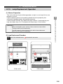
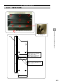
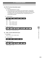
4.1.
Failure Display Functions
If a failure condition is detected, it will be displayed in some combination of the ON Indicator,
the Failure Indicator, and the Service Lamp.
In addition, if an anomaly other than these failures is detected, it will be stored as log data in
projector memory, and can be displayed in the menu screen.
ON Indicator
Indicates power and set in operation.
Illuminated when lamp failure or temperature
anomaly occurs.
Button Switch and LED Indicators
Service Lamp
Indicates internal circuit status. Used to
identify failure location.
Detailed Failure Assessment Methods ((((
Detailed Troubleshooting))))
Failure Indicator
4
I/O Terminal Panel(Main Board)
4-3
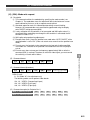
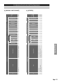
4.1.
Failure Display Functions
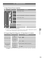
(1) List of Failure Assessments Made by Indicator
No.
1
Failure Indicator
Service Lamp
ON
Indicator LAMP TEMP ST1 ST2 CPU
Red
On
Lamp ASSY not inserted or
not fully inserted, causing
lamp illumination process
failure.
Insert the lamp ASSY correctly. Also,
in models with 2 lamps and a
changer, the other lamp has failed.
Lamp changer failure
Replace the lamp changer.
Rising temperature in lamp
activates temperature
sensor.
Rise in peripheral temperature,
blockage in fan exhaust, or drop in
fan rpm.
Circuit power protect has
been activated.
The following are possible causes.
Refer to the flowchart for
troubleshooting sequence.
(1) Circuit power failure
(2) Main board or drive board failure
(3) Inadequate circuit power cooling
caused by fan exhaust blockage,
etc.
(4) Inadequate circuit power cooling
when temperature sensor is
activated, circuit power protect is
activated
Abnormal voltage detected
on drive board.
Drive board must be replaced.
Fan stoppage or lowered
rpm detected.
Turn off the main power switch, wait
at least 20 seconds, and turn I back
on. Turn on the ON/STANDBY switch.
Identify fan failure from stopped or
lowered rpm fan RAS data displayed
on screen, and replace if needed.
-
3
Red
Flashing
-
4
Red
-
On
Red
7
Red
-
-
On
On
On
Flashing
8
9
10
On/Off Runaway main board CPU.
Green
Green
On
On
4
Detailed Failure Assessment Methods ((((
Detailed Troubleshooting))))
Lamp needs to be replaced. In
models with two lamps and a lamp
changer, both lamps must be
replaced.
Flashing
6
(see flowchart below for detail)
Lamp failure.
Red
Off
Likely Causes, Responses
-
2
5
Description
Main board must be replaced.
Failure in lamp not now
illuminated.
Replace the lamp and reset the lamp
operating time to zero.
Communication failure with
lamp changer.
Strong possibility next auto lamp
change will be impossible.
Check the wire connection (HD
connector. If this does not correct the
problem, then either the lamp changer
or main board will have to be
replaced.
Darkened areas are unrelated to failure assessment.
4-4
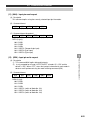
4.1.
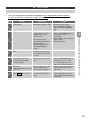
Failure Display Functions
(2) List of Failure Assessments Made by Indicator
Except for Items 6 and 9, the nature of the failure can be identified from the preceding List of
Failure Assessments Made by Indicator.
Choose [LOG DATA] [RAS] in the service person menu.
Item
RAS Screen Message
Description
Likely Causes, Responses
Abnormal
temperature
monitoring
ABNORMAL
TEMPERATURE
Rising temperature in
lamp activates
temperature sensor.
Fan failure
monitoring
FAN FAILURE
F1 F2 Fan stoppage or lowered Replace the fan indicated on-screen.
rpm detected.
Circuit voltage
monitoring
DRIVE BOARD CIRCUIT
ABNORMAL VOLTAGE
2.5V (or –10V、3.3V)
Abnormal voltage
detected on drive board.
The drive board must be replaced. However,
if all the indicator LEDs are off after the failure
occurs, then the likely cause is circuit power
defect or insufficient cooling.
4
Lamp failure
monitoring
LAMPx FAILURE
Lamp failure
Lamp has failed. Replace the lamp and zero
out lamp operating time.
NO LAMPx DETECTED
Lamp ASSY not inserted
or not fully inserted,
causing lamp
illumination process
failure.
Lamp ASSY not installed or not fully inserted.
5
Lamp not
installed
monitoring
6
Temporary
blackout
monitoring
TEMPORARY BLACKOUT Temporary blackout has
occurred, or power-off
has not been processed
correctly.
Likely cause is AC power voltage interruption
or faulty operation under AC noise.
Sometimes also caused by upgrading
projector software with the lamp illuminated.
Changer
operation failure
monitoring
LAMP CHANGE FAILURE
Lamp replacement did
not terminate normally.
Unless a communication failure with the lamp
changer has occurred (ST1 on with power
on), the lamp changer must be replaced.
Temporary blackout or
fault in data settings to
drive board.
This log is left after a very brief power outage,
unlike the log data in “temporary blackout.” If
the image is still displayed normally, there is
no problem posed by a flaw in the drive
board.
1
2
7
Drive board reset DRIVE BOARD RESET
monitoring
8
4
Detailed Failure Assessment Methods ((((
Detailed Troubleshooting))))
3
Rise in peripheral temperature, blockage in
fan exhaust, or drop in fan rpm.
(3) Using Lamp Log Data to Monitor Lamp Usage History
This log contains lamp usage history. Records of failure in this log are also listed under
“RAS data.” However, sometimes the Lamp Log data is more detailed.
Choose [LOG DATA] [LAMP LOG] in the service person menu.
Item
RAS Screen Message
Description
1
No. of retries
Stores in memory the number of times the lamp has been
TEMPERATURE WARNING illuminated by the lamp-on process. However, nothing is stored on
the first illumination.
2
Lamp failure
LAMPx FAILURE
NOT LIGHT UP
Displayed when lamp fails to illuminate during lamp-on process.
3
Failure during
illumination
LAMP1 FAILURE
LIGHT OUT
Displayed when a lamp that was on goes off because of
breakage, etc.
4
Lamp replaced
(changer)
LAMP CHANGE STATUS
LAMP12 (Example)
Log kept when lamp changer is activated, also indicates which
lamp was changed.
5
Changer abnormal
termination
LAMP CHANGE ERROR
LAMP1X (Example)
Displayed when system tries to activate lamp changer but the
process does not terminate normally.
6
Continuous illumination
time
CONTINUOUS LAMPx TIME
7
Power ON
POWER ON
Shows the length of time the lamp has been on continuously.
Displayed when power is on. No power-off log is kept.
4-5
4.2.
No.
List of Failures
Description
Flowchart
Optical power lamp does not come on (power does
not work).
1
2
Conspicuous color unevenness on screen.
2
3
One or two colors out of R, G, and B does not display,
or remains bright without changing.
4
None of the three colors R, G, and B display, and
remain bright without changing.
5
White (or gray or black) are close to R (or G or B).
5
6
Displayed screen is frozen.
6
7
Screen is too large (or small) from top to bottom.
7
8
Screen is too large (or small) from right to left)
8
9
“SIGNAL IS UNIDENTIFIED PLEASE SETUP”
displayed.
10
Screen is distorted. Display location is odd.
10
11
Screen is extremely dark.
11
12
Screen contrast is extremely poor.
12
13
Messages do not appear on-screen.
13
14
Remote controller does not work.
Power switch does not work.
14
15
Focus is poor.
15
16
Bright and dark lines appear on-screen.
16
17
Bright and dark dots appear on-screen.
17
Red
3
Yellow Magenta
White
Green
Cyan Blue
4
SIGNAL IS
UNIDENTIFIED
PLEASE SETUP
9
4
Detailed Failure Assessment Methods ((((
Detailed Troubleshooting))))
1
4-6
4.2.
List of Failures
Check the following when installing the video board. If the display does not come back up,
use the List of Failures to identify the source of the failure.
No.
Anomaly
・Image flutters vertically.
・Anomaly only in VIDEO1
(Composite) input, due to
faulty operation of Y/C
isolation circuit.
・Tape playback signal is
distorted when playing back
VCR tape images.
・VCR tracking is poor when
playing back VCR tape
images.
5
6
・Upper edge image appears
bent.
・If the image is from VCR
playback, probably the tape
has a copy protection signal
inserted.
・Thin black and white vertical
stripes appear iridescent.
Anomaly only with VIDEO1
(Composite) input.
・Cross-color noise phenomenon
with composite video signal
input.
・ Choose MODE ADJ. VIDEO
INPUT EXTENDED MENU 3D Y/C SEP. and set
to ”BYPASS.”
・Replace with tape with recording in
good condition.
・Adjust VCR tracking.
・ Choose MODE ADJ. VIDEO
INPUT EXTENDED MENU 3D Y/C SEP. and set to ”ON.”
・ Use S-terminal input when the
signal source has an S terminal.
・"NO SIGNAL”
・The sync signal from the video
board is not being input
“from HDU BOARD” displayed
correctly into the projector.
on-screen.
・Check the digital cable connection
between the projector and the
video board.
・Does not switch to video input ・Projector does not see a
connection with the video
when VIDEO key is pressed.
board.
・Turn the power OFF and check the
power supply cable connection
between the board ASSY and the
video board.
4
Detailed Failure Assessment Methods ((((
Detailed Troubleshooting))))
・Wrong input signal type setting. ・Check input signal settings.
Choose MODE ADJ. VIDEO
INPUT COLOR STANDARD
SEL
2
4
Response
No image visible.
1
3
Likely Cause
4-7
4.3.
Failure Assessment Flowchart
Start
Same phenomenon with remote
controller and power switch
operation?
YES
NO
Are the LEDs listed in the
NO
table on p.4-4 on or flashing?
14
C
Neither internal nor external signals display when power is turned ON/OFF.
YES
Look at the pattern of on/flashing
failure assessment indicators.
NO
Displays failure information on-screen in
the RC-300 or RC-300W remote
controller.
Choose or refer to material in the following pages as indicated
by the pattern of on/flashing failure assessment indicators.
4
Detailed Failure Assessment Methods ((((
Detailed Troubleshooting))))
YES
4-8
4.3.
Failure Assessment Flowchart
Flowchart: Inspection Flowchart Based on Failure Assessment Displays
“LAMP” Indicator ON
※ Go to following pages if other indicators are on or
flashing.
4
YES
Problem resolved?
NO
When you turn the main power switch
ON, after about 2 seconds do you
hear a "ksssh" sound from the power
board ASSY?
NO
A
YES
Replace the lamp ASSY.
Replace the main board.
YES
YES
Problem resolved?
Problem resolved?
NO
NO
Detailed Failure Assessment Methods ((((
Detailed Troubleshooting))))
Sometimes the indicator will not come on if the lamp
temperature is high immediately after the power goes
OFF. Turn off the main power switch, wait 5 minutes,
turn the power back ON again, wait 3 more seconds
and turn the ON/STANDBY button ON.
Replace the connector board.
Replace the lamp changer
(or lamp power).
YES
YES
Problem resolved?
Problem resolved?
NO
NO
B
END
4-9
4.3.
Failure Assessment Flowchart
“LAMP” Indicator Flashing
※Go to following pages if other indicators are on or
flashing.
NO
Is ST2 on?
NO
Install a lamp ASSY.
YES
YES
Check the lamp ASSY
installation condition.
Replace the lamp changer
(or lamp changer control
board).
Problem resolved?
NO
Replace the lamp changer
(or lamp changer control
board).
YES
Problem resolved?
YES
4
NO
Problem resolved?
NO
YES
Check the [HD] cable
connection.
Problem resolved?
NO
NO
Replace the main board.
Problem resolved?
YES
YES
Problem resolved?
Detailed Failure Assessment Methods ((((
Detailed Troubleshooting))))
YES
Is there a lamp ASSY at
the illuminated spot?
NO
Replace the
connector board.
NO
Problem resolved?
YES
B
END
4-10
4.3.
Failure Assessment Flowchart
“TEMP” Indicator ON
“CPU” Indicator Flashing or OFF
※Go to following pages if
other indicators are on or
flashing.
ST1 indicator ON?
“TEMP” Indicator Flashing
NO
Is there a fan that
is not working?
YES
YES
NO
Turn the main power
switch OFF, wait 20
seconds, and turn it
back ON.
Is the lamp cooling
fan working?
Replace the fan
that is not working.
NO
YES Problem resolved?
NO
YES
Has the rpm
dropped, or is it
making a strange
sound?
NO
YES
YES
Problem resolved?
Replace the main board.
NO
Replace the lamp
cooling fan.
Is the lamp cooling
fan exhaust path YES
clear?
Problem resolved? YES
Replace the
main board.
NO
NO
Replace the
lamp ASSY.
Replace the circuit
power ASSY.
Make room for
the exhaust
path.
YES
Problem resolved?
Problem resolved?
NO
NO
4
Detailed Failure Assessment Methods ((((
Detailed Troubleshooting))))
Go to “ST1 Indicator ON”
YES
Anomalous
phenomenon has
ceased.
Watch to see if it
reappears.
B
END
4-11
4.3.
Failure Assessment Flowchart
“ST1” Indicator ON
“ST2” Indicator ON
ON indicator is green
Replace the drive board.
ON indicator is red?
NO
4
YES
Problem resolved?
NO
Replace the lamp
changer.
Problem resolved?
NO
Replace the drive
board.
YES
Problem resolved?
NO
YES
Detailed Failure Assessment Methods ((((
Detailed Troubleshooting))))
YES
B
END
4-12
4.3.
Failure Assessment Flowchart
A
Replace the circuit power ASSY.
YES
Problem resolved?
Replace the LCOS-RL2 board on
top of the circuit power ASSY.
YES
Problem resolved?
NO
B
Detailed Failure Assessment Methods ((((
Detailed Troubleshooting))))
NO
4
END
4-13
4.3.
Failure Assessment Flowchart
C
Turn off the main power switch, wait at least 20 seconds, and turn it back on. Wait 3 seconds and press
the ON/STANDBY button to turn the power on.
With the power ON, the ON indicator
lights up green, and within 1 second
the power drops.
YES
The PFC circuit in the circuit power ASSY
is not working. Take a look at the [F8]
cable connection.
With the power ON, the optical
source lamp comes on once and
then the power drops.
NO
(Doesn’t come
on at all)
YES (Comes on once)
Does the power STANDBY
indicator come on along with
the "kssh" startup sound?
YES
NO
Power indicator goes off when the NO
lamp goes off.
YES
Replace the main board.
This phenomenon probably results from activation
of the temperature sensor, one of which is located
near each light source lamp, on each lamp power
board, and on the power board. The anomaly is the
same for each temperature sensor activated.
Problem resolved? YES
NO
【Responses】
(1) Is the ambient temperature high? The
operating temperature range for this set is
5~35OC.
(2) The cooling fan aeration may be
insufficient. Check the lamp fan and power
cooling fan.
Replace circuit
power ASSY.
Problem
resolved?
Replace the
connector board.
NO
Problem
resolved?
YES
Check the [VX]
cable connection.
YES
YES
4
Detailed Failure Assessment Methods ((((
Detailed Troubleshooting))))
NO
NO
Problem resolved?
NO
B
Replace the circuit power
ASSY.
YES
Problem resolved?
Is the resistance NO
value 0Ω (short
circuit)?
YES
NO
With the power turned off, use a
tester to measure the resistance
on both [HD] connectors (3) and
(4) on the lamp changer.
Replace the lamp
changer (temperature
sensor).
END
4-14
4.3.
Failure Assessment Flowchart
2
Check LCOS operating time (=UNIT TIME).
Is it near the recommended
replacement time?
Adjust color unevenness.
Replace components
and adjust.
Problem resolved?
Problem resolved?
NO
YES
NO
YES
Are you able to correct color
irregularity, but not completely?
NO
YES
Replace the main board.
Replace the optical engine.
Problem resolved?
Problem resolved?
NO
NO
YES
Detailed Failure Assessment Methods ((((
Detailed Troubleshooting))))
YES
4
YES
NO
Replace the drive board
(=optical engine).
YES
Problem resolved?
B
NO
Replace the connector board.
Problem resolved?
NO
YES
END
4-15
4.3.
Failure Assessment Flowchart
3
NO
RGB input?
YES
Does the phenomenon
revolve around the cable YES
when you change the
cable on the input terminal
Replace the video board.
(Option)
4
Problem resolved?
YES
Replace the main board.
YES
Problem resolved?
NO
Are internal allwhite/patch/OSD displayed
correctly?
YES
NO
Replace the drive board
(=optical engine).
YES
Detailed Failure Assessment Methods ((((
Detailed Troubleshooting))))
Check the input signal
and cables.
NO
NO
Problem resolved?
NO
Replace the optical engine.
Problem resolved?
NO
YES
B
END
4-16
4.3.
Failure Assessment Flowchart
4
Same phenomenon with
all image signals?
NO
YES
Problem with video
image?
Replace the video board.
(Option)
Replace the main board.
YES
NO
Problem resolved?
Problem resolved?
NO
Are internal allwhite/patch/OSD displayed
correctly?
NO
YES
YES
Replace the drive board
(=optical engine).
YES
4
There may be a problem
with the signal setup.
Refer to Chapter 9 so you
can do a correct setup and
adjustment.
Detailed Failure Assessment Methods ((((
Detailed Troubleshooting))))
YES
NO
Problem resolved?
NO
Replace circuit power ASSY.
Problem resolved?
NO
YES
B
END
4-17
4.3.
Failure Assessment Flowchart
5
Same phenomenon with
all image signals?
NO
YES
NO
Problem with video
image?
4
COMMON COLOR CONTROL
DRIVE COM and adjust.
YES
Replace the video board.
Problem resolved?
Problem resolved?
NO
YES
NO
Replace the main board.
Replace the main board.
YES
YES
Problem resolved?
Problem resolved?
NO
NO
Are internal allwhite/patch/OSD displayed
correctly?
YES
Replace the
connector board.
NO
Replace the drive board
(=optical engine).
Problem resolved?
NO
YES
Either there is a
problem with the signal
itself, or the
adjustment (DRIVE
adjustment, etc., for
each MODE) may be
inadequate. Refer to
Chapter 8 and perform
the adjustment.
Detailed Failure Assessment Methods ((((
Detailed Troubleshooting))))
YES
YES
Problem resolved?
NO
B
Replace the optical engine.
Problem resolved?
NO
YES
END
4-18
4.3.
Failure Assessment Flowchart
6
Same phenomenon with
all image signals?
NO
YES
Problem with the video
image?
YES
YES
Replace the video board.
(Option)
Problem resolved?
NO
NO Problem resolved?
Are internal allwhite/patch/OSD displayed
correctly?
YES
YES
NO
Replace the drive board
(=optical engine).
YES
Problem resolved?
NO
4
There may be a problem
with the signal setup.
Refer to Chapter 9 so you
can do a correct setup and
adjustment.
Detailed Failure Assessment Methods ((((
Detailed Troubleshooting))))
Replace the main board.
NO
Replace circuit power ASSY.
YES
Problem resolved?
NO
Replace the connector board.
Problem resolved?
NO
YES
B
END
4-19
4.3.
Failure Assessment Flowchart
7, 8
NO
Only video input?
YES
NO
YES
MODE ADJ. VIDEO INPUT COLOR STANDARD SEL. and
check.
Problem resolved?
YES
Problem resolved?
NO
NO
SCALING SCALING FACTOR
and adjust to enlarge the size.
Replace the main board.
Problem resolved?
NO
Problem resolved?
NO
YES
Replace the video board.
(Option)
NO
YES
4
Detailed Failure Assessment Methods ((((
Detailed Troubleshooting))))
There may be a problem with the
signal setup. Refer to Chapter 8
so you can do a correct setup
and adjustment.
Problem resolved?
YES
B
END
4-20
4.3.
Failure Assessment Flowchart
9
Check the INPUT and SAVE signal
frequencies in the SYNC SET
screen.
4
Are the frequencies
essentially the same?
Signal frequencies may have
changed. Use an oscilloscope, etc.
to measure the actual frequencies.
Press the CLEAR key twice and
perform a SYNC SET.
YES Is the frequency displayed by the
projector the same as that
measured by the oscilloscope?
Did the message go off?
NO
NO
The signal has changed.
Check the system
including the signal
source. You may have to
do a SET UP depending
on the situation.
YES
Detailed Failure Assessment Methods ((((
Detailed Troubleshooting))))
NO
YES
Replace the main board.
Problem resolved?
NO
YES
B
END
4-21
4.3.
Failure Assessment Flowchart
If on-screen messages are
not visible, press the All White
key or the Patch key to
display the internal signal.
10
Same phenomenon with
all image signals?
NO
Adjust PLL CONTROL
PFD GAIN/VCO GAIN.
YES
Problem resolved?
Replace the main board.
YES
Problem resolved?
NO
Are internal allwhite/patch/OSD displayed
correctly?
NO
7, 8
YES
Replace the drive board
(=optical engine).
YES
Problem resolved?
NO
YES
Detailed Failure Assessment Methods ((((
Detailed Troubleshooting))))
NO
4
Replace circuit power ASSY.
YES
Problem resolved?
NO
Replace the connector board.
Problem resolved?
NO
YES
B
END
4-22
4.3.
Failure Assessment Flowchart
11
Same phenomenon with
all image signals?
NO
YES
NO
YES
YES
Replace the lamp ASSY.
YES
4
Problem with video image?
Check clamp
adjustments.
Replace the video board.
Problem resolved?
Problem resolved?
NO
YES
YES
Problem resolved?
NO
NO
Replace the main board.
Replace the main board.
Revise the
setup.
YES
YES
Problem resolved?
Problem resolved?
NO
NO
Problem resolved?
NO
Are internal allwhite/patch/OSD displayed
correctly?
YES
Replace circuit
power ASSY.
YES
Detailed Failure Assessment Methods ((((
Detailed Troubleshooting))))
Still dark even when NO
set to FULL
BRIGHT?
NO
Replace the drive board
(=optical engine).
YES
Problem resolved?
NO
NO
Problem resolved?
Replace the
connector board.
YES
NO
Problem resolved?
B
YES
END
4-23
4.3.
Failure Assessment Flowchart
12
Same phenomenon with
all image signals?
NO
YES
NO
Replace the main board.
4
Problem with the video
image?
YES
NO
Problem resolved?
Check clamp
adjustments.
Replace the video board.
NO
Are internal allwhite/patch/OSD displayed
correctly?
Problem resolved? YES
NO
YES
Problem resolved?
NO
NO
Replace the main board.
Revise the
setup.
Replace the drive board
(=optical engine).
Problem resolved?
Problem resolved?
YES
NO
NO
Problem resolved?
YES
NO
Replace circuit
power ASSY.
YES
Detailed Failure Assessment Methods ((((
Detailed Troubleshooting))))
YES
YES Problem resolved?
NO
Replace the
connector board.
YES
Problem resolved?
NO
Replace the
optical engine.
Problem resolved?
NO
B
YES
END
4-24
4.3.
Failure Assessment Flowchart
13
External signal itself
normal?
NO
YES
Letters appear onscreen?
Problem resolved?
NO
NO
Mode set for no on-screen letters. Do a
new setup in AUTO SELECT under
MODE INITIAL SETUP.
Problem resolved?
NO
YES
YES
Detailed Failure Assessment Methods ((((
Detailed Troubleshooting))))
YES
4
Replace the main board.
Press the All-White key or Patch
key to display the internal signal.
B
END
4-25
4.3.
Failure Assessment Flowchart ト
If neither are operational,
then diagnose the problem
as shown in flowchart (1).
Remote controller does not
work.
Power switch does not work.
Replace remote controller
batteries.
Replace the switch board.
Problem resolved?
Problem resolved?
NO
YES
YES
NO
Replace remote controller.
Replace the main board.
Problem resolved?
Problem resolved?
NO
YES
NO
Replace the controller board.
Replace the remote controller
photoreceptor board.
YES
4
Problem resolved?
Problem resolved?
YES
Detailed Failure Assessment Methods ((((
Detailed Troubleshooting))))
YES
14
NO
NO
Replace the main board.
Problem resolved?
NO
B
YES
END
4-26
4.3.
Failure Assessment Flowchart
15
Does focus improve when
you press the screen?
NO
YES
4
Problem resolved?
NO
YES
B
END
Detailed Failure Assessment Methods ((((
Detailed Troubleshooting))))
The screen comprises two
components: a front sheet and a
Fresnel sheet.
This phenomenon results from
gaps between the two caused
by moisture absorption and
temperature change.
Observe the condition, and if it
does not improve, contact (the
factory).
Replace the optical engine.
4-27
4.3.
Failure Assessment Flowchart
16
Are areas other than bright lines and NO
dark lines normal?
YES
Same even with internal
signal?
NO
6
6
4
YES
NO
Replace the drive board (=optical
engine).
YES
Problem resolved?
Clean the
screen/mirror.
Problem resolved?
NO
YES
Replace the optical engine.
Problem resolved?
NO
B
NO
Detailed Failure Assessment Methods ((((
Detailed Troubleshooting))))
YES
Dirt on screen or mirror?
YES
END
4-28
4.3.
Failure Assessment Flowchart
17
Are areas other than
bright spots and dark
spots normal?
YES
NO
Same with internal
signals?
NO
6
4
NO
Likely cause is
bright and
dark spots on the LCOS
panel.
YES
Within specifications on
product spec sheet?
NO
Replace the optical engine.
Digital input?
YES
NO
Digital transmission
noise within the unit
sometimes produces
bright spots.
Replace the main board.
DIGITAL INPUT ***
EDGE GOING and
change the settings.
YES
Problem resolved?
NO
YES
Problem resolved?
NO
A degree of digital noise
can remain with digital
transmission depending
on the image content.
Detailed Failure Assessment Methods ((((
Detailed Troubleshooting))))
YES
Replace the drive board
(=optical engine).
YES
Problem resolved?
NO
B
END
4-29
4.3.
Failure Assessment Flowchart
B
The component thought to be the source of the problem has been replaced. Consequently, the
likely cause is not the component, but rather a poor contact or a short.
Check the wiring pathways (connectors, board ASSY, etc.) with replaced components against the
wiring diagram and look for bad connections and wiring damage.
4
Detailed Failure Assessment Methods ((((
Detailed Troubleshooting))))
4-30
5
Inspection Methods (Cleaning, Parts Replacement)
5.1.
Inspections
5.2.
Inspection Methods
5-1
5.1.
5.1.1.
Inspections
Inspection Items (Cleaning/Checking)
One service person*1 is needed for the inspections listed below.
No.
1
Item
Clean screen
Clean unit lens glass surface
2
3
Time Required
(Minutes)
2 (15)*2
2 (5)
*2, *4
*2
Special Tools, Etc.
Gauze, water, neutral cleanser
Lens cleaner
1 (15)
Clean mirror
2 (30)*2
See 5.2.3
Check lamp operating time
(Replace lamp)
2 (35)*3
Remote controller
(See “2.7.2 Check Operating Time” for how to
check operating time.)
2 (20) *3
Remote controller
“7.3.2 Gamma Adjustment and Uniformity
Adjustment Using Internal Signals” for how to check
and adjust.)
4
Check for color unevenness
(Readjust screen)
5
Loose input plugs
Lens cleaner
2
*1 : If a failure has occurred that necessitates removing the main unit, two service people may
be needed.
*2 : Parenthesized figures show time required for cleaning.
*3 : Includes adjustment time.
*4 : Dust on the lens surface degrades screen brightness and produces horizontal lines in the
image. We request that you inspect and clean at replacement time (yearly, or after 8,000
hours).
5.1.2.
5
Inspection Methods (Cleaning, Parts Replacement
Clean lens surface
List of Parts Replaced at End of Service Life and
Replacement Consumables
The following table lists replacement parts. (Time required is per unit.)
No.
Item
Replacement Criterion
Replacement
Time [Hours]
Time
Required
[Minutes]
1
Optical engine (LCOS panel)
Check operating time screen
display (UNIT TIME)
50,000*1
2
(70)*2
2
Fans
Check operating time screen
display (UNIT TIME)
50,000*1
2
(15 ~ 25)*2
3
Plugs
Special
Tools, Etc.
*1 : Check updated service news and service parts list.
*2 : Includes adjustment time.
5-2
5.2.
5.2.1.
Inspection Methods
Inspection Methods
The following section describes how to check for dirt on the screen. It also describes
possible causes for your reference.
(1) Screen Dirt Inspection Method
Switch the screen to an all-white pattern (internal all
white), and visually inspect from a distance of 2m
from the screen.
(2) If there is dirt on the screen
2m
Line dirt
Probaby from dirt on inner
screen surface
Dirt spotches
Likely from oil or dirt on mirror
surface.
Screen condition
5
Inspection Methods (Cleaning, Parts Replacement
Causes: screen, mirror
The dirt in the illustration below is not on the
outer screen surface, but rather on the inner
surface or on the mirror surface. This is almost
always the case. Remove the rear cover of the
cabinet and look inside to check.
(3) Horizontal Lines Visible on Screen
Cause : multiple clumps of dirt on the lens surface causes horizontal lines, as shown
below. This degrades brightness. When this phenomenon becomes prominent,
examine the lens surface.
Screen
condition
5-3
5.2.
Inspection Methods
5.2.2. Screen Inspection/Cleaning
Please refer to the following for instructions on removing the screen.
Size
Model
Reference
50 inch
ES50-116CM
See 2.2.1
70 inch
ES70-116CM
See 2.2.1
(1) Inspection Method
Project an all-white pattern (internal all-white)
and visually check the screen while moving
the first row of seats (2m from screen) left and
right.
5
No stripes due to dust on the screen.
2m
(3) Cleaning Method
Follow the cleaning guidelines below when needed because of dirt (dust, fingerprints,
etc.) on the outer and inner screen surfaces.
Remove the rear cover of the set to clean the rear screen surface.
Clean the upper portion of the screen and other hard-to-reach areas by putting lens
cleaner on the tip of a stick. Be careful not to damage the screen in the process.
(4) Cleaning Method for the Screen Front Surface
・ Lightly wipe away dust with a soft cloth (gauze, flannel, Bemcot) or a soft feather
duster.
・ To clean off fingerprints, etc., dampen a soft cloth (gauze, flannel), squeeze it out
thoroughly and lightly wipe the dirt away.
・ To clean off oily dirt, put neutral cleanser on a soft cloth, squeeze the cloth out
thoroughly, and lightly wipe the dirt away. Wipe again with water to make sure
there is no cleanser residue.
Inspection Methods (Cleaning, Parts Replacement
(2) Assessment Criterion
【Warning】
・ Do not rub the screen hard enough to make a squeaky sound, since this can
leave tiny damage marks.
・ Do not use polishing cleaners, chemical scrubbing cloths or volatile compounds.
・ Make sure not to touch the mirror, etc., while your body is inside the cabinet
cleaning the inner surface of the screen.
・ Clean hard-to-reach spots by attaching gauze to a stick. Be careful not to cause
any damage while doing so.
5-4
5.2.
5.2.3.
Inspection Methods
Mirror Inspection and Cleaning
(1) Inspection Method
Project an all-white pattern (internal all-white) and visually check the screen while
moving the first row of seats (2m from screen) left and right.
(2) Assessment Criterion
No image deterioration due to mirror dirt.
Determine whether the dirt is on the screen or the mirror by looking from the rear.
(3) Cleaning Method
Remove the rear cover from behind in order to clean the mirror.
See Section 5.2.3..
Inspection Methods (Cleaning, Parts Replacement
【Warning】
・ Do not rub the mirror roughly even if you can’t clean the mirror by gently wiping
the dirt away (to keep from damaging it).
・ Do not use water, deodorizing or polishing cleansers, chemical scrubbing cloths
or volatile compounds.
5
5-5
5.2.
Inspection Methods
5.2.4. Projector Reflecting Mirror (Front Surface Mirror)
Cleaning Method
【Warning】
The projector employs a front surface mirror as reflecting mirror in order to improve
imaging performance.
Front surface mirrors have glass surfaces covered with metal that is either vapor
deposited or spattered on. These mirror surfaces are very thin and unprotected,
and are easily damaged. Accordingly, we ask you to follow the illustration and to
do the cleaning work without damaging the mirror at all.
5
(1) Cleaning Tools
(A) Air duster
1/2 can
(B) Cotton swabs
100g
(C)
Remarks
Scissors (for cutting cotton
swabs)
(D) New protective gloves
(E)
Distilled water or filtered
water
(F) Gauze
(G) Alcohol solvent (ethanol)
30cm (wide) x 5m (long)
Use only for heavy dirt buildup that
cannot be removed with water.
Normally (E) should suffice.
Inspection Methods (Cleaning, Parts Replacement
Estimated Quantity
Used Per Mirror
5-6
5.2.
Inspection Method
5.2.4. Projector Reflecting Mirror (Front Surface Mirror)
Cleaning Method
(2) Cleaning Procedure
Start
Read <Warning 1> Carefully
Clean mirror surface thoroughly with an air duster (to prevent mirror
damage from dust residue).
5
YES
Attach a nozzle to the air duster.
Put the nozzle tip next to the dust and
blow it away.
NO
Read <Warning 3> Carefully
Look at the mirror surface carefully and make sure there aren’t
already score marks on the mirror. If there are, document the
damage (before cleaning).
Is there any cloudy dirt?
YES
Read <Warning 4> Carefully
Soak a cotton swab in filtered water and
lightly wipe against the mirror surface to lift
off dirt.
Before drying, soak up water droplets left on
the mirror surface with gauze, cotton swabs
or mirror cleaners.
Use a soft touch to keep the surface of the
glass always clean.
NO
Read <Warning 6> Carefully
Display the projector all-white screen, and
assess whether there is anything wrong with
the image on-screen. Also determine
whether mirror damage has progressed
since before cleaning.
Read <Warning 7> Carefully
Use the air duster to remove any dust
residue from the mirror surface.
Inspection Methods (Cleaning, Parts Replacement
Read <Warning 2> Carefully
Look at the mirror surface carefully.
Is there any dust or dirt residue?
Read <Warning 5> Carefully
Soak a cotton swab in alcohol solvent and
wipe off any cleaning unevenness or
noticeable spots.
(Lightly moisten with solvent.)
END
5-7
5.2.
Inspection Methods
5.2.4. Projector Reflecting Mirror (Front Surface Mirror)
Cleaning Method
<Warning (1)>
Air Duster Usage Procedure and Warnings
Do not attach the nozzle. (attach only if you can’t remove the dust otherwise)
1
Shake thoroughly
5
Spray until white mist stops
coming out.
3
Blow away dust.
(Do not hold with the spray can
tilted downward.)
Inspection Methods (Cleaning, Parts Replacement
2
Move slowly.
【Warnings】
・ Make sure in Step 2 that you spray until the white mist stops coming out. The white
mist will cover the mirror with cloudy impurities.
・ Make sure in Step 3 not to tilt the can downward. If you do it will spray out white mist
used for cooling, and this will cover the mirror with impurities.
・ Move the spray can slowly. If you move it rapidly it will spray out white mist.
・ Blow away dust from the entire mirror surface without attaching the nozzle.
<Warning (2)>
Checking the Mirror Surface for Dust
・ It is of utmost importance to thoroughly remove dust, because if there is any dust
residue, the next cleaning operation will damage the mirror. Dust will scratch the
surface of the mirror just like sandpaper powder.
・ Look closely to make sure there is no dust left on the mirror. (This is easiest to do by
looking at the mirror from an angle with the all-white screen projected on the mirror.)
Almost always there will be some hard-to-clean dust residue. Put the spray can
nozzle near that dust and blow it away completely.
5-8
5.2.
Inspection Methods
5.2.4. Projector Reflecting Mirror (Front Surface Mirror)
Cleaning Method
<Warning (3)>
Checking the Mirror Surface for Damage Before Cleaning
When checking the mirror surface for damage, be sure to turn off fluorescent lighting in the
room, display the projector all-white screen, and view the mirror surface from an angle. This
method allows you to check for shallow score marks on the mirror surface (normally hard to
see).
If there already is damage to the mirror surface, document the damage condition.
The reason for documenting the damage is to make a final judgment as to whether mirror
cleaning will produce further damage. For this purpose, document the condition in as much
detail as possible.
1
Either wash your hands thoroughly and swab them off, or wear never-used protective gloves.
Use scissors to cut the cotton swabs into a readily usable size (about 10 cm x 10 cm).
5cm x 5cm is OK if the dirty surface area is small.
Absolutely do not tear the cotton swabs. This produces a large amount of fiber dust that is a big
problem to clean off later.
2
Soak the cotton swabs completely in filtered water or distilled water and gently wring them out.
If you don’t wring them out enough, wiping the mirror clean will leave water droplets.
3
Use the cotton swab to wipe the dirty surface horizontally, touching it gently with pressure so light
that you have no sense you are pressing against the glass (1st time).
Only wipe the dirty area when cleaning. Wiping the area that is clean can cause damage.
Absolutely do not reuse cotton swabs a second time. Use a new swab every time you wipe the
surface.
Also, check as you work that there is no damage in the wiped areas (see Warning (3)).
4
Next, take in one hand a piece of cotton gauze soaked in filtered water and gently wrung out, and
take in the other hand a piece of dry gauze. Wipe the surface a second time as described in Step 3
above. (Wring out the swabs in the same manner as in Step 3.)
Wipe water droplets left on the mirror surface with cotton swabs and soak them up immediately with
gauze. The gauze will also get dirty, so always use a new surface to soak up droplets.
The reason for immediately soaking up water droplets with gauze is that the droplets contain dirt
that was on the mirror, as well as dirt from the atmosphere that was dissolved in the water. If the
water droplets dry on the surface, this dirt will be left on the surface also. (see illustration below)
Shine a light on wiped areas in the center.
1
2
3
Gauze
Dab to soak up droplets
1
Soak up water droplets after wiping.
2
Soak up water droplets after wiping.
3
Soak up water droplets after wiping.
4
Soak up water droplets after wiping.
5
Soak up water droplets after wiping.
6
Soak up water droplets after wiping.
5
Inspection Methods (Cleaning, Parts Replacement
<Warning (4)>
Procedure for Cleaning the Mirror Surface with Filtered Water and Cotton Swabs,
and Warnings
4
5
Swabs
Example of Cleaning When Entire Mirror Surface is Soiled
5-9
5.2.
Inspection Methods
5.2.4. Projector Reflecting Mirror (Front Surface Mirror)
Cleaning Method
<Warning (5)>
Cleaning with Alcohol Solvent (Ethanol)
Use scissors to cut cotton swabs into pieces about 5cm x 5cm in size.
Moisten the cotton swab with a small amount of alcohol solvent (about the amount that
will dry immediately after wiping), and wipe the areas with wiping streaks and residual dirt
(noticeable areas only), doing so gently, with no sense of pressing against the glass.
<Warning (7)>
Removing Residual Dust from the Mirror Surface
Before finishing the mirror cleaning process, use a safety duster to remove gauze fiber
waste residue from the mirror surface.
When you use gauze to soak up water droplets left on the mirror surface during cleaning,
tiny dust particles from gauze fibers are left behind on the surface. It is difficult to remove
this dust residue a half-year later at the next scheduled inspection, so make sure you do
so before completing the cleaning operation.
5
Inspection Methods (Cleaning, Parts Replacement
<Warning (6)>
Problem Assessment
If mirror damage has progressed compared to before cleaning, document it and file a
report with the (DMD) quality assurance department. (Verify whether the damage causes
image deterioration.)
There may not be any problem with the on-screen image even if there is some damage
on the mirror. However, a cleaning method that produces further damage will eventually
impact the image if repeated. Accordingly, you must report it to (DMD) quality assurance
and share your cleaning method expertise.
5-10
5.2.
5.2.5.
Inspection Methods
Lens and Unit Lens Glass Cleaning Guidelines
1
Remove the rear cover (see 2.1).
2
If there is any significant amount of dust
or dirt on the glass and lens, use the air
duster to blow it away.
5
3
Remove the unit lens glass fastener
hardware (8 screws) and cleans both
sides of the glass with lens cleaner.
Make sure not to touch the glass surface
and mirror during removal.
Inspection Methods (Cleaning, Parts Replacement
Unit lens glass
Do not touch the inside mirror surface.
Do not touch the unit lens glass surface.
Unit lens glass fastener hardware
5-11
5.2.
5.2.5.
Inspection Methods
Lens and Unit Lens Glass Cleaning Guidelines
Unit lens glass
It doesn’t matter whether front or back faces
outward, but do not change the way it is
oriented as installed.
5
4
Lens
If there is any significant amount of dust
or dirt on the glass and lens, use the air
duster to blow it away.
【Wiping Away Dust】
When you can’t remove all the dust and
dirt with the air duster, wipe he lens
gently with lens cleaner (or eyeglass
cleaner).
Wipe the glass and lens with a circular
motion working from the center outward.
Do not rub the surface vigorously
enough to make a sound.
Inspection Methods (Cleaning, Parts Replacement
Unit lens glass
Work in reverse order to reassemble.
5-12
5.2.
5.2.6.
Inspection Methods
Lamp Changer Cleaning Guidelines
The lamp changer was not included among the inspection items. However, dirt can
accumulate on the sensors in the changer and cause malfunctions. The following section
describes how to clean the sensors when this happens.
1
Remove the rear cover (see 2.1) and take out the LCOS changer ASSY (see 2.6.9).
2
Cleaning the changer mirror
Blow air onto the mirror in the optical
pathway aperture in the removed
changer to blow away dirt.
【Warning】
Mirror
Air duster
3
Cleaning the changer mirror (rear
surface)
Remove 2 screws from the protective
cover and take off the cover (one side
held in place by a snap-on structure).
4
Use the air duster to blow dust off the
mirror.
Inspection Methods (Cleaning, Parts Replacement
Only use an air duster to blow air for
cleaning. Do not wipe the mirror under any
circumstances, since this can lead to failure.
5
Protective cover
Air duster
5-13
5.2.
5.2.6.
Inspection Methods
Lamp Changer Cleaning Guidelines
5
Cleaning the changer sensor unit
Use the air duster to blow dust away in
the areas indicated in the photographs,
with the protective cover removed.
5
5.2.7.
Sensor
Inspection Methods (Cleaning, Parts Replacement
Air duster nozzle
Color Balance Checking and Adjustment Method
Please refer to “7.3.2 Gamma Adjustment and Uniformity Adjustment Using Internal
Signals.”
5-14
6
Mechanical Adjustments
– 6-Axis Adjustment and Mirror Adjustment –
6.1.
Adjustment Specifications
6.2.
Adjustment Procedure Overview
6.3.
6-Axis Adjustment
6.4.
Adjusting The Mirror
6-1
6.1.
6.1.
Adjustment Specifications
(1) Projector Single Screen Size and Location Specification
Defined as the relative position of the two outermost lines for the internal cross-hatch
signal and the screen periphery location in the projector single screen size and location
specification.
[Requirement Specfication]
Adjust the screen periphery so it is located between the two outermost internal crosshatch signal lines. However, the third line can be inside the screen periphery.
Screen edge
Outermost 2 lines
1st line
6
(2) Adjacent Screen Misalignment Specification
Defined in terms of the degree of internal cross-hatch signal disparity at screen seams.
[Required Specification]
Line position misalignment d at the seam must be 0 line ≦d ≦1 line.
6-Axis Adjustment and Mirror Adjustment
2nd line
Seam misalignment
d
6-2
6.1.
6.2.
Adjustment Procedure Overview
(1) Adjusting the Screen
in the very center and work your way toward the sides.
(3)
[Upper
(2) access method]
Remove upper set rear
(1)
【Warning】
If the expanded screen display used by the system has been selected, give priority to
the expanded display when adjusting the links between screens.
Start
(1) Adjust vertical and horizontal
trapezoidal distortion and rotation.
(2) Adjust position (X,Y)
6-Axis Adjustment and Mirror Adjustment
(2) Adjusting the 6-Axis Adjustment Screen Position
6
(3) Adjust size (expanded, minimized)
(Adjust mirror: only when needed)
(Single screen) adjustment complete
Adjust adjacent screen misalignment
Adjustment complete
6-3
6.1.
6.2.
Adjustment Procedure Overview
The various distortions do not change in isolation. Rather, they affect one another as they
change. Every time the various adjustments are performed, the state of adjustment of all the
adjustments performed in the past have to be checked and readjusted as needed. As these
repeated adjustments occur over and over, the various distortions are corrected, and at that
point the single-screen position adjustment process (6-axis adjustment) comes to an end.
Next you must check for misalignment between adjacent screens and perform minor
adjustments.
Also, if there is localized distortion (see graphic), you should adjust
the mirror (see “6.4. Adjusting the Mirror” for details on mirror
Corner is elevated.
adjustment). Then check for adjacent screen misalignment and
perform minor adjustments.
After adjusting and checking, go on to the next screen.
Please note the following items when making adjustments.
6-Axis Adjustment and Mirror Adjustment
【Warnings】
(1) Make sure the axis lock screws (4 spots) are loosened, that fastener screws are
loosened, and that transport hardware fastenings are released.
(2) If when you are turning the adjustment screw you feel it tighten up again or if it won't
move at all, immediately stop rotating in the current direction of motion.
(You have already exceeded the adjustment range, so continuing to rotate the screw
will break the adjustment hardware.)
(3) Use the internal cross-hatch signal when making adjustments. Make sure you are at
the electrical center point before starting adjustment.
[FACTORY ADJ.] [LCOS CONTROL] [PANEL POS] “H : 126 / V : 25”
6
6-4
6.1.
6.3.
6.3.1.
6-Axis Adjustment
Preparation
(1) Tools Required
・ Philips head screwdriver (+2)
・ Ball-point driver and hex wrench (2mm, 5mm)
・ Single-head spanners (2 units, 7mm, 13mm)
6
Position
adjustment
hardware
Fastening
hardware
Transport
hardware
Enlarged view of unit (showing screen location adjustment apparatus)
(2) Preparation Procedure
1
Remove rear cover B (screws: 8, see 2.1 for
details).
2
Release transport hardware
Remove fastening screws (2 spots) and loosen
the nuts.
6-Axis Adjustment and Mirror Adjustment
Operation guide label
Enlarged
Single-head
spanner
(7mm)
Fastening
screws
(2 spots)
Single-head spanners
(2 units, open 13 mm)
Nuts
6-5
6.1.
6.3.
6.3.1.
6-Axis Adjustment
Preparation
3
Turn the bolt and pull it up to the highest level.
6
4
Loosen the 6-axis fastener screws (Philips
screws: 5 spots). (about 1 ½ rotations)
5
Use a hex wrench to loosen the axis lock screws
(worm screws hex 2mm: 4 spots).
6-Axis Adjustment and Mirror Adjustment
Transport hardware fasteners
released.
Enlarged
6-6
6.1.
6.3.
6-Axis Adjustment
6.3.2. Detailed Adjustment Hardware Operating Method
Refer to the operating guide label (shown belwow) stuck to the back side of the unit while
you are operating the adjustment hardware.
【Warning】
The screen changes shown on the label illustrate the changes as seen by a person
operating the adjustment hardware. Changes as seen by a viewer are reversed.
Please be aware of this.
Tools Used
- Ball-point driver and hex wrench
(open: 5mm)
6
Shaft switching lever hardware
Shaft and adjustment
screw
Carry out the shaft switching operation first as
shown below when an adjustment is indicated at
the shaft location.
<Shaft switching procedure>
(1) Lift up the lever hardware.
(2) Move the shaft.
(3) Lower the lever hardware.
6-Axis Adjustment and Mirror Adjustment
【Warning】
Lever
hardware
6-7
6.1.
6.3.
6.3.2.
6-Axis Adjustment
Detailed Adjustment Hardware Operating Method
Changes in Displayed Screen (Patch)
Adjustment Tool Operation
(1) Vertical trapezoidal
distortion (V-Keystone)
Shaft Position (Right)
(2) Horizontal trapezoidal
distortion (H-Keystone)
Shaft Position (Right)
(3) Rotations (Rotations)
6
Shaft Position (Either OK)
(5) Y direction motion (Y
Position)
6-Axis Adjustment and Mirror Adjustment
Shaft Position (Either OK)
(4) X direction motion (X
Position)
Shaft Position (Either OK)
(6) Size variation (Size)
Shaft Position (Left)
【Warning】
After completing adjustments, make sure to tighten the axis lock screws (4 spots)
and the six-axis fastener screws (5 spots).
6-8
6.1.
6.4.
Adjusting the Mirror
The ES50/ES70-116CM is equipped with a mirror adjustment mechanism that provides a
means to make localized positional adjustments. This mechanism makes these localized
screen position adjustments by pulling and pushing against the mirror. Accomplish this by
turning attachment screws located near the spots you wish to adjust.
Push Screw : M4 3P screw
Push to adjust
6
Mirror
Pull Screw: M4 3P
bolt (hex head)
Adjustment
screw side
Pushing the mirror
reduces the screen
Pulling the mirror
enlarges the screen
6-Axis Adjustment and Mirror Adjustment
Pull to adjust
【Warnings】
・ Adjacent push and pull screws will not work simultaneously (stopper prevents operation of
other screw).
If you want to pull after pushing, you have to loosen the push screw. If you want to push after
pulling, loosen the pull screw.
・ Mirror adjustment does not necessarily produce the screen changes shown in the illustration.
(Example: the screen may change only up and down or left and right, or the area not in
contact with the screw may change at the same time.)
If this happens, loosen all the mirror adjustment screws and reconsider this as nominal.
6-9
6.1.
6.4.
Adjusting the Mirror
6.4.1. ES50-116CM
Upper mirror adjustment
screw expanded
6
Mirror adjustment screw locations (7)
Middle, lower adjustment screws expanded
Access by removing rear cover A,
【Warning】
Remove when adjusting the mirror
standard position centering screw.
[Upper access method]
Remove upper set rear
cover A, take off the
adjustment screw cover and
access from inside the set.
6-Axis Adjustment and Mirror Adjustment
Upper
[Middle, lower access method]
Remove rear cover A from the
set being adjusted and access
from inside the set.
6-10
6.1.
6.4.
Adjusting the Mirror
6.4.2. ES70-116CM
6
Adjustment screw
enlarged
Upper
6-Axis Adjustment and Mirror Adjustment
Mirror adjustment screw locations (9)
[Upper access method]
Remove upper set rear cover
A, take off the rubber
adjustment screw cover and
access from inside the set.
[Middle, lower access method]
Access from the back of the set
being adjusted.
6-11
7
Electrical Adjustments 1 - Adjustments Using Internal
Signals (Gamma Adjustment, Uniformity Adjustment) -
7.1.
Adjustment Procedure Flowchart (Electrical Adjustments)
7.2.
Adjustment Procedure Digest
7.3.
Adjustment Procedures
7.4.
Multi-Screen Color Balance Adjustment
7.5.
ID Remote Control Operation Method
7-1
7.1.
Adjustment Procedure Flowchart (Electrical Adjustments)
This section present flowcharts for the following adjustments (1) through (3). Please refer
to “2.6.2 Optical Engine (Including LCOS Panel, Drive Board)” for how to perform
adjustments when replacing optical components.
(1) Adjustments at setup and when adding new signal added
(2) Adjustments at inspection time
(3) Adjustments after lamp replacement
First complete mechanical adjustments before starting these adjustments.
(1) Adjustments at Setup and When Adding New Signal
Start
(Standard adjustment time
per screen, in minutes)
7.3.1.
Adjustment preparations (heat run of 30 minutes of more)
30
7.3.2.
Gamma adjustment and uniformity adjustment using internal signals*1
60
5
8.1.1.
Choose setup data and settings and determine clamp locations.
5
8.1.2.
Check frequency presets.
1
8.1.3.
Set sampling clock.
5
8.1.4.
Set scaling factor and adjust position.
5
8.1.5.
Set cable compensation and adjust image sampling phase.
2
8.1.6.
Adjust external signal brightness, color
10
8.1.7.
Check display condition, perform other settings.
10
Have you performed the adjustments for all signal sources*2?
8.1.8.
Set auto-scan*1
END
(*1) Not always needed when adding new signal.
(*2) When performing settings for multiple enlarged screens with different enlargement ratios, you have to set the proper scan
mode for each ratio. In this instance, if you set it to auto-scan, the system calls the scan mode with the newest number.
Accordingly external scan mode control is needed from an AV controller or RS232C link, etc.
Electrical Adjustments 1 ―――― Adjustments Using Internal Signals (Gamma Adjustment, Uniformity Adjustment)――――
Input an external signal and assign a scan mode.*2
7
7-2
7.1.
Adjustment Procedure Flowchart (Electrical Adjustments)
(2) Adjustments at Inspection Time
(Follow this procedure to check, and readjust maladjusted items as needed.)
(3) Adjustments at Lamp Replacement Time
Start
(Standard adjustment time
per screen, in minutes)
7.3.1.
Adjustment preparations (heat run of 30 minutes of more)
30
7.3.2.
Gamma adjustment and uniformity adjustment using internal signals*1
60
Input an external signal and assign a scan mode.*2
5
Choose setup data and settings and determine clamp locations.
5
8.1.2.
Check frequency presets.
1
8.1.3.
Set sampling clock.
5
8.1.4.
Set scaling factor and adjust position.
5
8.1.5.
Set cable compensation and adjust image sampling phase.
2
8.1.6.
Adjust external signal brightness, color
10
8.1.7.
Check display condition, perform other settings.
10
Have you performed the adjustments for all signal sources*2?
8.1.8.
Set auto-scan*1
END
Electrical Adjustments 1 ―――― Adjustments Using Internal Signals (Gamma Adjustment, Uniformity Adjustment)――――
8.1.1.
7
7-3
7.2.
1
Adjustment Procedure Digest
Adjustment Preparation
(1)
Use the special cable to connect the remote controller to the main unit.
You can also use a wireless controller, but with a wired controller you don’t have to think
about which direction it is pointed, and this makes the adjustments a bit easier.
【Warning】
When there are two or more displays, using a wireless controller will cause
adjustments to display on the screens not being adjusted. In this case, you must use
a wired controller.
(2)
(3)
(4)
2
Gamma Adjustment and Uniformity Adjustment Using Internal Signals
(1)
(2)
(4)
(5)
(6)
(7)
(8)
Choose Setup Data and Settings and Determine Clamp Locations (Each Mode)
(1)
(2)
(3)
(4)
(5)
4
Set the scan mode to “0.”
Navigate COMMON GAMMA ADJ TABLE 0 MACRO GAMMA (3p) to enter 3point macro-gamma adjustment mode. Check the brightness and color balance for each
contrast level and adjust as needed.
If you want to make more precise adjustments, navigate COMMON GAMMA ADJ TABLE 0 MACRO GAMMA (5p) to enter 7-point macro-gamma adjustment mode
Check the brightness and color balance for each contrast level and adjust as needed.
If you want to make still more precise adjustments, navigate COMMON GAMMA ADJ
TABLE 0 MICRO GAMMA to enter 15-point micro-gamma adjustment mode.
Check the brightness and color balance for each contrast level and adjust as needed.
Choose COMMON UNIFORMITY NORMAL ADJ.
Use MACRO, MACRO SUB and MICRO modes to adjust so the entire screen is uniform.
Choose COMMON UNIFORMITY LOWER LEVEL ADJ MID to display the lowbrightness screen. Check to see if this entire screen is uniform. If not, adjust it so it is a
uniform gray color.
Choose COMMON UNIFORMITY LOWER LEVEL ADJ DARK to display the
extreme-dark screen Check to see if this entire screen is uniform. If not, adjust it so it is a
uniform gray color.
Press the EXT key to display an external image.
Navigate MODE INITIAL SET UP SET UP (Input Signal) AUTO SETUP. Selecting
Auto-Setup as the display mode automatically chooses and displays setup data.。
Set the scan mode being adjusted to “TO.”
Press the COPY key to copy the setup data to the scan mode in (3).
If you cannot brighten the display, it is possible that the clamps are not set correctly.
Navigate MODE ADJ. RGB ANALOG INPUT CLAMP POS and adjust the clamp
locations.
Check Frequency Presets (Each Mode)
(1)
(2)
(3)
(4)
Press the EXT key to display an external image.
Navigate MODE INITIAL SETUP SYNC SET to display the status of the presets.
Make sure that the value of “INPUT” and the value of “SAVE” are essentially the same.
If not, press the CLEAR key twice to store the input frequency in memory.
7
Electrical Adjustments 1 ―――― Adjustments Using Internal Signals (Gamma Adjustment, Uniformity Adjustment)――――
(3)
3
Turn on the power to the display.
Display the D/A output 255/255 beta white screen.
Conduct a heat run of at least 30 consecutive minutes.
7-4
7.2.
5
Adjustment Procedure Digest
Set Sampling Clock (Each Mode, RGB Analog)
(1)
Press the EXT key to display an external signal.
OK even if the screen displays vertical stripes or many letters.
(2)
Navigate MODE ADJ. RGB ANALOG INPUT SAMPLE CLOCK to enter sampling clock
setting mode.
(3) Adjust so that regular stripes disappear and the entire screen looks the same.
If displayed during interpolation, make sure that SMOOTHING is OFF
6
Set Scaling Factor and Adjust Position (Each Mode)
(1)
(2)
(3)
(4)
Press the EXT key to display an external signal.
Set the scaling factor.
Navigate MODE ADJ. SCALING SCALING FACTOR to make the setting.
Set the scaling section.
Navigate MODE ADJ. SCALING MAG.SECTION to set the display section.
Smoothing during scaling
Navigate MODE ADJ. SCALING SMOOTHING to make the setting.
Normally, when an enlarged image is displayed, choose "1. Apply (or turn Off) light smoothing."
Navigate MODE ADJ. POSITION to align the displayed position with the appropriate position.
【Warning】
Image is interpolated when the scaling factor is not an even number.
7
Adjust Image Sampling Phase (Each Mode, RGB Analog Only)
8
Adjust External Signal Brightness, Color (Each Mode)
(1)
(2)
Press the EXT key to display an external signal.
Navigate MODE ADJ. RGB ANALOG INPUT SAMPLE PHASE to enter sampling phase
adjustment mode.
(3) Notice any vertical lines on the screen, and adjust if noise is present.
(1)
(2)
(3)
(4)
Press the EXT key to display an external signal.
Navigate MODE ADJ. RGB ANALOG INPUT INPUT OFFSET and adjust so the black
portion of the input signal is inverted to white.
Navigate MODE ADJ. RGB ANALOG INPUT INPUT LEVEL and adjust so the white
portion of the input signal is inverted to black.
When you wish to change the color and brightness settings:
Adjust high brightness by navigating MODE ADJ. COLOR CONTROL DRIVE
Adjust low brightness by navigating MODE ADJ. COLOR CONTROL BLACK LEVEL
9
Check Display Condition and Perform Other Settings (Each Mode)
10
Set Auto-Scan
11
Record Projector Setting Data
(1)
(2)
(1)
(2)
(3)
Press the EXT key to display an external signal.
Check the display condition and if any of the conditions described in this section are present,
make the appropriate settings.
Take out the accompanying projector setting data record sheet.
(from the accessory storage box)
Update the record of projector setting data.
Put the sheet back in the storage box.
Electrical Adjustments 1 ―――― Adjustments Using Internal Signals (Gamma Adjustment, Uniformity Adjustment)――――
(5)
7
7-5
7.3.
Adjustment Procedures
7.3.1. Adjustment Preparation
Procedure
1
Use the special cable to connect the
remote controller to the main unit.
You can also use a wireless controller, but with a
wired controller you don’t have to think about
which direction it is pointed, and this makes the
adjustments a bit easier.
【Warning】
There is an ID function for the projector main unit. For details see “7.3 ID
Remote Controller Operating Method.”
Turn the AC SW on the set main unit to ON [ O I ], then turn the power button on the
front of the set to ON.
3
Press the WHITE key on the remote controller to display the [255/255 beta white signal]
screen.
4
Conduct a heat run for at least 30 consecutive minutes (to balance the temperature of the
internal circuit elements and adjust the display under stable conditions).
Differences in Adjustment Procedure Depending on Setting Differences
This function determines whether color balance (Drive Com) and gamma/uniformity
adjustment are based on individual data for lamps 1 and 2 or on identical data.
Before starting adjustment, navigate FACTORY→COLOR DATA SETTING(LAMP1/2)→
DRIVE COM and FACTORY→COLOR DATA SETTING(LAMP1/2)→GAMMA/ UNIFORMITY
to check the setting, and if it is set to separate adjustment, adjust both lamps 1 and 2. Note
that the projector automatically switches data for lamps 1 and 2.
IDENTICAL
INDIVIDUAL
DRIVE COM
Adjustment data is the same even
when lamps 1 and 2 are replaced.
Normally lamp 1 is adjusted.
Adjustment data is separate. Therefore,
after adjusting lamp 1 you must switch to
lamp 2 and adjust it similarly.
GAMMA/UNIFORMITY
Same as above.
Same as above.
When shipped from the factory, the unit
has had both lamps adjusted by an
automatic adjuster.
【Warning】
Do not change this setting after automatic adjustment terminates.
In particular, if you change the setting from [Identical] to [Individual], the data for one of
the lamps that has been separately adjusted (the lamp currently illuminated) will be
overwritten and lost.
7
Electrical Adjustments 1 ―――― Adjustments Using Internal Signals (Gamma Adjustment, Uniformity Adjustment)――――
2
7-6
7.3.
7.3.2.
Adjustment Procedures
Gamma Adjustment and Uniformity Adjustment
Using Internal Signals
(1) Purpose
Perform the following adjustments using internal signals.
・ Adjust color irregularity in the screen of each projector.
・ Adjust color disparities between each projector to settings in the gamma table in
Drive COM.
(2) Basic Sequence of Gamma Adjustment and Uniformity (Color Irregularity)
Adjustment
The basic sequence of gamma adjustment and uniformity adjustment is described below.
This sequence must be followed the first time this projector is adjusted.
Performing uniformity adjustment alters gamma properties. As a result, when you do a
uniformity readjustment you must also do a gamma adjustment.
(3) Concerning Gamma Adjustment
The input signal voltage-brightness properties of LCD panels do not have a linear form, unlike
CRT properties. Gamma adjustment is the process of compensating for the I/O properties
(gamma properties) from low brightness to high brightness to bring them closer to the
properties of CRTs.
The gamma table is a table of input/output values used to perform this compensation.
Brightness output
γ=2.2
G2 = ((L2/L1)^2.2) × G1
G1
G2
L2
L1
CRT I/O Properties
Input value
7
Electrical Adjustments 1 ―――― Adjustments Using Internal Signals (Gamma Adjustment, Uniformity Adjustment)――――
【Sequence of Gamma Adjustment and Uniformity Adjustment】
Drive COM Adjustment Gamma Adjustment Coarse Uniformity Adjustment Fine
Gamma Adjustment Fine Uniformity Adjustment
7-7
7.3.
7.3.2.
Adjustment Procedures
Gamma Adjustment and Uniformity Adjustment
Using Internal Signals
(3) Concerning Gamma Adjustment (Continued)
There are two types of gamma adjustment for this LCOS rear projector:
1)CRT gamma
2)VT gamma
The gamma tables for the two are related as shown below.
2)
)VT gamma
1)
)CRT gamma
Input value
Output value
7
Image signal output
Image signal input
VT Gamma
The overall form of the VT gamma table appears below.
Because of the properties of the LCOS panel, when there is no gamma compensation the low
and medium grayscale contrast levels turn completely black (Fig. A). Here the setting is
properties close to those of a CRT (Fig. B) at low-to-medium brightness levels.
This adjustment is normally performed at the factory using an automatic gamma adjustment
system. Doing this adjustment manually for no reason causes flicker and panel burn-in.
Please do not perform this adjustment except in an emergency.
Output value
Output value
Input value
Fig. A No VT gamma compensation
Input value
Fig. B With VT gamma compensation
Electrical Adjustments 1 ―――― Adjustments Using Internal Signals (Gamma Adjustment, Uniformity Adjustment)――――
Input value
Output value
7-8
7.3.
7.3.2.
Adjustment Procedures
Gamma Adjustment and Uniformity Adjustment
Using Internal Signals
CRT Gamma
The overall form of CRT gamma is shown below. The initial value is linear (Fig. C). In this
instance, the output value of VT gamma as described above is the same as the CRT gamma
output value.
Manually adjusting CRT gamma allows you to alter the final input value to the panel. This
makes it possible to perform the adjustment without worrying about panel burn-in, which is an
item of concern with VT gamma adjustment. Note that intermediate adjusted contrast levels
are interpolated to linear form (Fig. D).
Pressing Clear + Clear during adjustment restores the line shown in Fig. C.
Output value
Output value
7
Fig. C Before CRT gamma compensation
Fig. D After CRT gamma compensation
(4) Types of Gamma Adjustment Methods
Adjustment Method
Summary
Description
MACRO GAMMA (3p)
Most generally used adjustment
method.
Limited to 3 adjustable contrast levels,
simplified adjustment.
During adjustment, intermediate
contrast levels are automatically
interpolated.
MACRO GAMMA (5p)
Used when contrast level continuity is 2 points added that are not adjustable
difficult to obtain from MACRO GAMMA under MACRO GAMMA (3p),
(3p) adjustment.
increasing adjustment precision.
During adjustment, intermediate
contrast levels are automatically
interpolated.
MICRO GAMMA
Used for touch-up work on specific
contrast levels that cannot be
accurately adjusted using MACRO
adjustments.
Possible to freely adjust all contrast
levels, but difficult to adjust smoothly.
Electrical Adjustments 1 ―――― Adjustments Using Internal Signals (Gamma Adjustment, Uniformity Adjustment)――――
Input value
Input value
7-9
7.3.
7.3.2.
Adjustment Procedures
Gamma Adjustment and Uniformity Adjustment
Using Internal Signals
(5) Gamma Adjustment Procedure
Adjustment Content
1
Set the mode number to “0.”
Navigate COMMONCOLOR CONTROLDRIVE COM. To
adjust the color 255/255 white. (This color is the basis for all
mode numbers. If you want to make signal-specific color
adjustments (for each mode number), adjust by navigating
MODE ADJ. COLOR CONTROL DRIVE.)
2
Press the WHITE key several times to display grayscale
(shown at left).
7
3
Choose COMMON GAMMA ADJ. TABLE 0 MACRO
GAMMA(3p) to enter Macro Gamma (3p) adjustment mode.
4
Press color adjustment key G to enter color G adjustment
mode. Arrows are displayed in the section undergoing contrast
level adjustment.
Press the choose to select the contrast level.
Press the to adjust it darker.
Press the to adjust it lighter.
5
Compensate by pressing an arrow key while depressing ADJ.
ADJ + makes it more distinct.
ADJ + makes it much more distinct.
ADJ + makes it less distinct.
ADJ + makes it much less distinct.
Electrical Adjustments 1 ―――― Adjustments Using Internal Signals (Gamma Adjustment, Uniformity Adjustment)――――
If the colors at medium brightness
are not correct in relation to high
brightness, then perform the
following adjustments.
7-10
7.3.
7.3.2.
Adjustment Procedures
Gamma Adjustment and Uniformity Adjustment
Using Internal Signals
You can select contrast levels of “3,” “9,” or “15.” Adjust at
these contrast levels. During adjustment, intermediate contrast
levels are automatically interpolated.
6
Contrast level “15”: brightness ratio to level “16” = 0.86
Contrast level “9”: brightness ratio to level “16” = 0.28
Contrast level “3”: brightness ratio to level “16” = 0.03
Take away “floating” black and glare onto the screen at contrast
level “0.”
Check to make sure that the color adjusted in □
6 above exhibit
7
a smooth gradation to dark colors.
-
If so, go on to □
7 and adjust other colors.
If brightness is uneven or if the color is different at each
brightness level, go to □
8 and adjust.
8
As in Steps □
4 ~□
6 , perform macro gamma adjustment on R
9
Repeat steps □
4 ~□
6 to make adjustments.
and B.
If you are still unable to make a smooth adjustment at any particular
contrast level, navigate COMMONGAMMA ADJTABLE
0MACRO GAMMA(5p) to increase the number of points in the
adjusted contrast level and perform the adjustment there. If the result
is still unsatisfactory, navigate COMMONGAMMA ADJTABLE
0MICRO GAMMA to individually adjust the particular contrast level.
10
Press the END key until “SAVE” is displayed to end
adjustments.
Electrical Adjustments 1 ―――― Adjustments Using Internal Signals (Gamma Adjustment, Uniformity Adjustment)――――
-
7
7-11
7.3.
7.3.2.
Adjustment Procedures
Gamma Adjustment and Uniformity Adjustment
Using Internal Signals
(6) Concerning Uniformity (Color Irregularity) Adjustment
Color irregularity adjustment compensates for color irregularity in the screen to produce color
uniformity. This process also compensates for brightness irregularity in the screen.
This projector supports a maximum of five levels of color irregularity adjustment. Intermediate
levels are interpolated by an LSI in the projector.
Adjustment Method
Summary
Description
NORMAL ADJ.
Generally used adjustment method.
Displays a medium gray.
Limited to 1 adjustable contrast
level, simplified adjustment.
During adjustment, intermediate
contrast levels are automatically
interpolated.
LOWER LEVEL ADJ. - MID
Used when adjustment from NORMAL Interpolation applied only near the
ADJ. is inadequate.
low-brightness gray contrast level
displayed on screen.
Displays a low-brightness gray for
adjustment, with contrast levels
displayed from DARK to bright.
Used when adjustment from NORMAL Interpolation applied only near the
ADJ. is inadequate.
very low-brightness gray contrast
level displayed on screen.
Displays a very low-brightness gray
for adjustment, with contrast levels
displayed from MID to bright.
LEVEL FIXED ADJ.
Supports five levels of adjustment:
BRIGHT、MID(H)、MID(L)、DARK、
DARKEST.
Adjustments can be made at all
five levels, allowing for precise
color irregularity adjustment.
The following three adjustment modes are available for each adjustment method:
・ Macro adjustment (MACRO) : (5 x 5) adjustment points (white circles below)
・ Macro sub-adjustment (MACRO SUB) : (4 x 4) adjustment points (black circles below)
・ Spot adjustment (SPOT) : (45 x 35) adjustment points
Macro adjustment points (image diagram)
When you navigate MacroSub-MacroSpot, the adjustment range per single point
shrinks, resulting in more localized adjustment. Use each of the three modes separately
according to the extent of the color irregularity.
-
-
Sub-macro adjustment moves a marker to the middle of the macro adjustment point. If the
original color irregularity was smooth, macro adjustment should suffice by itself. If macro
adjustment alone does not yield good results, because color irregularity is spotty, or because
the irregularity is severe, use sub-macro adjustment before you use spot adjustment.
Spot adjustment works only on a very small area. It is difficult to get good color and brightness
balance, so we recommend it not be used except by very skilled operators.
Electrical Adjustments 1 ―――― Adjustments Using Internal Signals (Gamma Adjustment, Uniformity Adjustment)――――
LOWER LEVEL ADJ. - DARK
7
7-12
7.3.
7.3.2.
Adjustment Procedures
Gamma Adjustment and Uniformity Adjustment
Using Internal Signals
Concerning the 5 Adjustment Levels
As discussed earlier, this projector supports five levels of contrast adjustment. In order by
brightness, these are BRIGHT, MID(H), MID(L), DARK, and DARKEST. The values of these
five adjustment levels are set at the factory using an automatic color irregularity adjuster. The
remote controller cannot be used to alter the adjustment levels.
”Output” is fixed for these adjustment levels (see illustration). Changing the value of
DRIVE.COM causes a fluctuation in the value “*/255,” indicating the input value displayed
when entering adjustment mode. However, there is no change in “output” for the adjustment
points.
An interpolated linear value compensates for color irregularity between these levels.
Output
value
255/255
after
adjustment
255/255
before
adjustment
7
0
MID (H)
(H)
DARK
DARKEST
MID (L)
(L)
BRIGHT
Input
value
5 Level Adjustment Points and Relationships to Drive COM
Concerning the Adjustment Principle for NORMAL ADJ.
NORMAL ADJ assumes that LCOS panel color irregularity properties are identical from low
brightness to high brightness. For instance, if the upper right of the screen is tinted magenta
(not enough green) at one level, it assumes that the same position is tinted magenta from low
brightness through high brightness.
In the example above, not enough green on the upper right of the screen from low through
high brightness makes it possible to do one color irregularity adjustment for all levels. Color
irregularity adjustment is actually gamma adjustment of each adjustment point on the LCOS
panel. Accordingly, it is possible to extrapolate from panel VT properties how much to
compensate for green at each level from low brightness to high brightness.
In other words, when the compensation value is determined for one level, it is then possible
to obtain the compensation value for other levels.
Electrical Adjustments 1 ―――― Adjustments Using Internal Signals (Gamma Adjustment, Uniformity Adjustment)――――
Changing DRIVE COM : 512→
450 changes BRIGHT LEVEL :
200/255 → 180/255.
However, the adjustment point
does not move, so “output”
does not change in relation to
the various points.
7-13
7.3.
7.3.2.
Adjustment Procedures
Gamma Adjustment and Uniformity Adjustment
Using Internal Signals
Concerning NORMAL ADJ. (Continued)
The following illustration shows the relationship between contrast levels and gamma adjustment
values and between contrast levels and output brightness (with γ=2.2). If “brightness” in the
upper right at level x is changed by only A, color irregularity within the screen becomes uniform,
and if brightness in the upper right at level x’ is changed by only A’, then color irregularity within
the screen becomes uniform. In this instance, “contrast level” must be changed by only a and a’ in
the upper right of the screen. Since the relationship between the contrast level and output
brightness has a gamma 2.2 for the relationship between a and a’, the following equation is true.
a' = ((x'/x)^2.2) × a
To change the contrast levels by only a and a’ gamma compensation values of δ and δ'
respectively must be added. Since the gamma compensation value and the color irregularity
compensation value are the same, adding color compensation values of δ and δ' completes
color compensation at the various contrast levels. Thus, if the panel properties are identical from
low through high brightness and gamma adjustment can be performed routinely, color irregularity
compensation results for one level can be applied to other levels. This inter-polation method is
how NORMAL ADJ handles color irregularity adjustment for all levels.
δ
Relationship between contrast level
and gamma compensation value
δ'
0
Contrast level
(input)
Brightness
a
A
Relationship between contrast level
and output brightness
(γ=2.2)
a'
A'
0
x'
x
Contrast level
(input)
Electrical Adjustments 1 ―――― Adjustments Using Internal Signals (Gamma Adjustment, Uniformity Adjustment)――――
Output (gamma compensation value)
7
7-14
7.3.
7.3.2.
Adjustment Procedures
Gamma Adjustment and Uniformity Adjustment
Using Internal Signals
(7) Uniformity Adjustment Procedure
Adjustment Content
1
Go into service person adjustment mode and set the mode
number to “0.”*1
Navigate COMMONUNIFORMITYNORMAL ADJ. and
choose MACRO、MACRO SUB、or MICRO.
The contrast level to undergo color irregularity adjustment is
displayed.
2
Press the “adjust color” key to go into color irregularity
adjustment mode for the color to be compensated. Use the
arrow keys on the remote controller to align the marker with
the adjustment point you want to adjust.
↑ key moves the marker up.
(All white)
w * * /255
(All white)
3
Compensate by pressing an arrow key while depressing ADJ.
ADJ + makes it more distinct.
ADJ + makes it much more distinct.
ADJ + makes it less distinct.
ADJ + makes it much less distinct.
This operation switches the compensated color using the adjust
color key (RGB key) while adjusting the entire screen to a
uniform bright gray.
4
Navigate COMMONUNIFORMITYMID and choose
MACRO, MACRO SUB, or MICRO.
The level to undergo color irregularity adjustment is displayed.
Check the color irregularity condition of the screen.
5
If you believe the adjustment is not adequate, adjust using
6
Navigate COMMONUNIFORMITYDARK and choose
MACRO, MACRO SUB, or MICRO.
The level to undergo color irregularity adjustment is displayed.
Check the color irregularity condition of the screen.
7
If you believe the adjustment is not adequate, adjust using
w * * /255
(All white)
w * * /255
steps □
2 ~□
3 .
steps □
2 ~□
3 .
*1 : If autoscan is ON, then pressing the END key will automatically engage autoscan even if the mode number
has been changed by pressing the MODE key. In this instance, press ADJ + SUB to go into service person
adjustment mode, specify the mode number at MODE CHANGE, then press the END key once to enable
service person adjustment for this mode number. If you want to forcibly set the mode number to "0," press
the CLEAR key twice.
7
Electrical Adjustments 1 ―――― Adjustments Using Internal Signals (Gamma Adjustment, Uniformity Adjustment)――――
key moves the marker down.
key moves the marker left.
key moves the marker right.
7-15
7.3.
7.3.2.
Adjustment Procedures
Gamma Adjustment and Uniformity Adjustment
Using Internal Signals
(8) Concerning Color Adjustment
LCD projectors use a variety of color adjustment mechanisms.
For the sake of economy, all of the adjustments related to color are listed here and their color
adjustment roles summarized. (However, this does not include LCD CONTROL and other
adjustments included in FACTORY ADJ.)
Role
Identical
Adjusts the input level in the RGB analog input AD
converter unit. The mode is identical, and this
adjustment compensates for AD converter
disparities.
Identical
Adjusts the input level offset in the RGB analog
input AD converter unit. The mode is identical, and
this adjustment compensates for AD converter
disparities.
Input (3) INPUT LEVEL
Adjustment (4) INPUT OFFSET
Individual
Individual mode adjustment for (1).
Individual
Individual mode adjustment for (2).
(5) CONTRAST(*1)
Individual
Adjusts brightness (video input).
Corresponds to INPUT LEVEL for RGB input.
(6) BRIGHTNESS(*1)
Individual
Adjusts black level (video input).
(7) TINT(*1)
Individual
Adjusts color phase (tone) (video input).
(8) COLOR(*1)
Individual
Adjusts color depth (video input).
(9) GAMMA ADJ
Identical
Adjusts the GAMMA compensation curve.
(10) DRIVE COM
Identical
Adjusts output amplitude. Output in accordance
with the adjusted GAMMA curve. Mode is identical,
and adjustment at this time yields the color
standard.
(11) BLACK SETUP
Identical
Raises the output black level only (levels 0-2
gamma). Adjust when there is a need to align the
black levels for multiple screens. Functions
differently from BLACK LEVEL, which has a mode
of individual.
DRIVE
(12) (PICTURE and COLOR
adjusted by user)
Individual
Individual mode adjustment for (10).
Individual
Adjusts the output offset. Brightness level shifts in
all brightness areas in accordance with the
adjusted GAMMA curve. Since high brightness is
saturated, you must check DRIVE.
Identical
Sets the maximum level capable of driving the LCD
panel. Except for FULL BRIGHT, no other
adjustment can produce a brightness level higher
than set here.
No.
Adjustment
(1) INPUT LEVEL COM.
(2) INPUT OFFSET COM
Output
Adjust(13) BLACK LEVEL
ment
(14) MAX BRIGHT ADJ.
Sets the panel to FULL BRIGHT mode. Produces
brightest possible display.
(15) FULL BRIGHT
-
【Warning】
The 255/255 all-white displayed by pressing
the WHITE key is not the maximum
brightness. The brightness displayed is that
after DRIVE adjustment.
7
Electrical Adjustments 1 ―――― Adjustments Using Internal Signals (Gamma Adjustment, Uniformity Adjustment)――――
MODE
Individual/Identical
Type
7-16
7.4.
7.4.1.
Multi-Screen Color Balance Adjustment
Color Balance Adjustment Procedure
Gamma adjustment must have been completed for all screens.
1
Set the value of DRIVE COM. to “512” for all colors on all screens.
2
Display 255/255 all white and select the darkest screen as the reference screen.
3
Adjust reference screen 255/255 color with DRIVE COM.
4
Display single color G on all screens.
5
In single-color green, adjust the brightness of 255/255 of other screens to the brightness of 255/255
color G in the reference screen, with DRIVE COM.
6
Next, in the MACRO GAMMA (3p) procedure, adjust the
brightness of all contrast levels to the same as the
reference screen.
(All white) 12 (All white) 12
W192/255
W192/255
(All white) 9
144/255
(All white) 3
48/255
(All white) 3
48/255
7
Check macro gamma for each contrast level in single-color green. Look at the entire multi-screen
image, and if there are disparities in brightness between screens, do a color irregularity adjustment to
produce uniformity. (brightness differentials can easily occur between the four corners)
8
Next, display all colors and do a gross color balance adjustment of the reference screen.
9
If this step fails to yield color balance between screens at a particular contrast level, navigate
COMMON GAMMA ADJ TABLE 0 MACRO GAMMA(5p) to go into gamma adjustment mode
and adjust the color balance of that contrast level.
10
11
12
Observe the colors at each contrast level in macro gamma, and if there is any color irregularity
between screens in the entire multi-screen image, do a color irregularity adjustment to make it uniform.
If you perform a color irregularity adjustment, do a fine adjustment in macro gamma adjustment.
If this step fails to yield color balance between screens at a particular contrast level, navigate
COMMON GAMMA ADJ TABLE 0 MICRO GAMMA to go into micro gamma adjustment mode,
and adjust the color balance for that contrast level.
【Warning】
Except when the color balance is extremely poor at a particular contrast level, please do
not use micro gamma adjustment mode for color G if there is no special need to do so.
If you must use it, display internal grayscale for each primary color and check to make
sure brightness changes occur smoothly for each contrast level.
Also, if you notice color differences on the black screen, navigate COMMONCOLOR
CONTROLBLACK LEVEL COM. to adjust the value and make the color uniform.
Electrical Adjustments 1 ―――― Adjustments Using Internal Signals (Gamma Adjustment, Uniformity Adjustment)――――
(All white) 9
144/255
7
7-17
7.5.
ID Remote Controller Operation Method
Using the ID remote control feature allows a specific projector alone to accept remote control
commands without having to use the remote controller cable.
This is convenient when making adjustments in multiple screens.
Operating Projector No. 3 Only in a 4-Screen Multi-Screen Configuration
1
PROJECTOR No.1
PROJECTOR No.3
PROJECTOR No.2
PROJECTOR No.4
First set the projector number. This
becomes the ID for specifying the
particular projector, so make sure there is
no duplication.
(Example at left shows settings for a 4screen multi-screen configuration)
7
MODE 0MODE ADJ
MODE INITIAL…
.
.
MODE 0MODE ADJ
MODE INITIAL…
.
.
MODE 0MODE ADJ
MODE INITIAL.
.
.
ID No**(PJ No.01)
MODE 0MODE ADJ
MODE INITIAL…
.
.
ID No **(PJ No.03)
MODE 0MODE ADJ
MODE INITIAL…
.
.
ID No **(PJ No.02)
MODE 0MODE ADJ
MODE INITIAL…
.
.
ID No **(PJ No.04)
MODE 0MODE ADJ
MODE INITIAL…
.
.
2
Press the ADJ + SUB keys to go into
service person adjustment mode for all
screens.
3
Send DISABLE (=ADJ + ENABLE ) to all
projectors.
"IDNo ** (PJ No.03)" in yellow in top row
Letters indicating (projector no. 3) appear.
This mode is a wait state for the ID (entered
via numeral keys) enabling remote control
reception.
After 5 seconds the message changes
to”DISABLE (PJ No.03)” in red, indicating
that all projectors have ceased to accept
remote control commands.
Electrical Adjustments 1 ―――― Adjustments Using Internal Signals (Gamma Adjustment, Uniformity Adjustment)――――
MODE 0MODE ADJ
MODE INITIAL…
.
.
7-18
7.5.
4
ID Remote Controller Operation Method
Send DISABLE (=ADJ + ENABLE ) again to the projector you want to operate. ”ID **(PJ
No.03)” appears in yellow as in □
3 . The other projectors will display the message ”ID
**(PJ No.xx)” in yellow, but this does not matter.
5
Again press the digits 0 and 3 on the numeral keys, corresponding to the ID code in the
yellow message ”ID **(PJ No.03).”
If the message on the specified projector does not turn green, repeat steps □
4 and □
5 .
ID No **(PJ No.03)
MODE 0MODE ADJ
MODE INITIAL…
.
.
ID No **(PJ No.02)
MODE 0MODE ADJ
MODE INITIAL…
.
.
ID No **(PJ No.04)
MODE 0MODE ADJ
MODE INITIAL…
.
.
The message ”ID 03 (PJ NO.03)” turns green
on No. 3 only. When this happens, only this
projector will accept remote control
commands. The green colored message will
go off after 5 seconds.
Because the ID does not match that of the
other projectors, the red message ”DISABLE
(PJ NO.xx)” stays on the screen.
【Warning】
The projector specifier number (ID) must be a
2-digit number. Enter 0 1 for projector no. 1
and 0 2 for projector no. 2.
6
To adjust other projectors, follow steps □
4 and □
5 and enter the two-digit ID number for
another projector.
7
To enable all projectors to accept remote control commands simultaneously, simply press
the ENABLE key. A green-colored “ENABLE” message appears without entering any ID
(using the numeral keys), and all projectors will accept remote controller transmissions.
In this mode, the projectors revert to DISABLE mode after 5 seconds pass with no
command (however, the projector that was set to remote control enable mode does
continue to accept commands).
【Reference】
This function is handy when you want to change the display state for all the multiple
screens while you are in the middle of adjusting one particular screen (to change from
internal signal display to external signal display, or to change the gamma adjustment
contrast level for all).
8
To terminate the ID remote control function, press the END several times while in the
ENABLE mode in step □
7 to quit service person adjustment mode. To use ID remote
control again, you will have to repeat the operations described in this section.
7
Electrical Adjustments 1 ―――― Adjustments Using Internal Signals (Gamma Adjustment, Uniformity Adjustment)――――
ID No**(PJ No.01)
MODE 0MODE ADJ
MODE INITIAL…
.
.
7-19
8
Electrical Adjustments 2
- Adjustments for External Signals (Setup)
)-
8.1.
External Signal Setup
8.2.
Projector Adjustment Data Record Sheet
8.3.
Setup Data Listing
8-1
8.1. External Signal Setup
8.1.1. Setup and Mode Numbers
Setup and Setup Data
The projector signal processing circuitry converts input signals into a signal format that
can be input into the LCD panel using a built-in scan converter. Therefore, to display
images correctly, image signal conversion formats have to be stored (setup) in the builtin scan converter. The result of the setup process (setup data) is stored in memory. This
projector is capable of storing multiple sets of setup data to make it compatible with
multiple signal sources and to store settings for expanded displays, etc.
Mode Numbers (Scan Mode Numbers)
Mode numbers (scan mode numbers are used to identify setup data stored in memory.
They are assigned as shown below according to application in the range 0-191. The
projector is shipped with preset setup data for typical signals (S000-S051 in the table).
This preset data is “original data” copied to mode numbers 1-127 for use. Users are not
allowed to overwrite these values.
Mode No.
0
1~127
Assignment
Basic adjustment
User area
(user free)
(preset data,
video input)
134~191*1 User area*1
(preset data
RGB signal)
S000
Default data
Use this to make basic adjustments to the projector. Its purpose is to
prevent adjustment mistakes and deviations from basic adjustment criteria
from items defined for each mode number. A portion of basic adjustment
(COMMON/FACTORY ADJ) can only be made in mode no. “0.”
・
Area free for user to use. Default data (S000) is stored for all modes
when shipped from the factory unless the customer specifies otherwise.
・ With RGB input, make the optimal adjustment in the SET UP menu
after copying the most appropriate from the preset data (S001-) data for
the signal being connected.
・ With video input, choose the input color format in the SET UP menu as
above.
・ Terminals where signals are input for each mode number are assigned
1-for-1. Autoscan (described below) searches all set up mode numbers
by the same input terminal.
Setup data is exclusively preset for video input. When the video input
terminal is selected by remote controller or the input switch button it must
be displayed in this mode number.
Various types of signal data are preset. If no user data is stored in the area
for modes 1-127, the projector automatically detects the most appropriate
data from the data in this area. The user can rewrite the adjustment
content.
Same as data stored as default in modes 0-127. The base is SXGA+.
The user cannot rewrite this data at will (read-only).
Preset data area
Stores video preset data. Can be copied to modes 1-127 for use.
~S006
S001
(video input)
The user cannot rewrite this data at will (read-only).
S007
~S051
Preset data area
Stores RGB preset data. Can be copied to modes 1-127 for use.
(RGB signal)
The user cannot rewrite this data at will (read-only).
*1 【Warning】
In this area there is a wide frequency range covered by preset data, so when multiple signals are
switched during input, the same mode number may be assigned even when the signal timing is
different. In this case, it may overwrite adjustment states performed later on. Mode numbers are
assigned for each terminal even if input comes from a different RGB terminal, and so subsequent
adjustments would of course be overwritten.
8
Electrical Adjustments 2 ―――― Adjustments for External Signals (Setup)――――
128~133 User area
Description
8-2
8.2. External Signal Setup
8.1.1. Setup and Mode Numbers
Setup Using Preset Data
For the projector to setup image signals to be displayed, it needs detailed timing data for
those image signals (resolution, horizontal/vertical sync frequencies, etc.). It is extremely
laborious to collect this data every time a new signal is connected. Accordingly, preset
data is provided to reduce the amount of trouble. The most appropriate data (closest to
the timing of the image signal being connected) can be chosen from the provided preset
data, copied to some part of the user area (modes 1-127) and detailed adjustment
performed on the display position based on this data.
【Warning】
The term “setup” in the explanation below means “the procedure for making adjustments so signals
are correctly displayed, based on the preset data” (as described above).
User Area and Preset Data
Mode numbers 1-127 and 128-191 both are areas available to users. However, as
shipped from the factory, the content of the presets differ for the two. The area 1-127 has
the content of S000 copied in, while 128—178 has the content of S001-051 copied on
(mode no. 128 contains preset S001, 129 S002, and so on).
Accordingly, even when modes 1-127 are not in use (not set up), the projector will
search for setup data that most closely resembles the input signal starting at mode no.
128 and higher. This makes it possible to display simple images even before a complete
setup has taken place.
Electrical Adjustments 2 ―――― Adjustments for External Signals (Setup)――――
Mode Number Selection (Autoscan)
)
When an image signal is input, the projector automatically searches for a mode number
and reads matching content from the setup data to display the image. The following
subsection describes how the autoscan operation searches for a mode number.
8
8-3
8.1. External Signal Setup
8.1.2. Mode Number Automatic Search (Auto-scan)
)
When there is a change in signal or in input, this projector searches for the optimal mode
number in mode numbers 1-191, in ascending order.
Mode No.
Procedure
0
(Not searched)
*1
1~127
(User area)
1
(A)
2
(B)
3
128~191
(Preset area)
(
(C)
*1 : When doing a setup using mode numbers 1-127, one of the input terminals RGB1, RGB2, and
RGB3 is assigned one-on-one to the mode number. As a result, the projector searches only
mode numbers to which selected input terminals (terminals with signal input) are assigned out
of all the mode numbers that were set up, which expedites processing.
Note that the only searchable input is RGB terminal. Even if the optional video input board is
added, video terminals are not auto-scanned.
【Reference】
To activate auto-scan, navigate MODE ADJ. OTHERS AUTO ON/OFF and set it to “ON.” The
factory default setting is “ON.”
1
The projector searches for a frequency stored in mode numbers 1-127 that
corresponds to the input, searching with the degree of precision shown below.
During searching, the projector starts with lower mode numbers (frequencies
stored in mode numbers are values stored during “SET UP” and “SYNC PRESET”
during “MODE INITIAL SETUP” adjustment).
H : ±1/100 V : ±1/150 or less
2
Next, if the search yields no mode that meets the above criteria, the projector
searches again for a frequency stored in mode numbers 1-127, searching with
the degree of precision shown below.
H : ±1/50 V : ±1/75 or less
3
If the projector cannot find a corresponding mode using Procedures 1 and 2, it
searches starting at mode no. 128 in ascending order. In this area the frequency
range that matches a single mode number is wide, and so signals with different
frequencies are sometimes included in the same range. In this instance, the
same mode number may be selected for different signals.
4
If there is no matching signal, the messages “SYNC IS OUT OF RANGE” or “NO
SIGNAL” are displayed.
Electrical Adjustments 2 ―――― Adjustments for External Signals (Setup)――――
Auto-scan Execution Content
8
8-4
8.1. External Signal Setup
8.1.3. Concerning Mode Numbers 134-191
Pay close attention to the following if you are doing a setup or adjustment using mode
numbers 134-191.
・ If mode numbers 1-127 are unused, the projector automatically assigns a mode
number from the range 134-191 based on input signal resolution and frequency.
*1
・ If input consists of a VGA/60, SVGA/60, XGA/60, SXGA/6, SXGA+/60, UXGA/60 or
1080i signal, data suitable for display of full-motion video (known as V-LOCK data,
described in detail below) is given priority for assignment .
*1 Terminal RGB3 does not support UXGA resolution.
・ When multiple signals are being adjusted, if the input signal resolution and frequency
is similar, the same mode is assigned. In this instance, the content of signals adjusted
earlier will be overwritten by content written later.
・ Automatically selected mode numbers can refer to signals with different timing. When
mode numbers are automatically selected, these signals cannot be adjusted using the
same mode number. Handle such situations as described below.
(i) If a computer is the signal source, change resolution and refresh rate under
screen property settings on the computer, and make the setting so that the
selected mode has a different number.
(ii) If you cannot make changes to computer settings, either use a mode number
between 1 and 127 for one signal, or reconfigure the projector as an externally
controlled device and use the external control device to designate the mode
number.
(A) MODE Key
MODE 120
H xx.xkHz
V xx.x Hz
No. xx
Preset
This number indicates the mode number
assigned to the currently connected signal. If the
number remains the same even when a different
signal is connected, this indicates that
adjustment data resides in the same memory
space.
Press the END key to return.
(B) MENU Key
USER 120(RGB1)
POSITION
H SIZE
SAMPLE PHASE
PICTURE
This number indicates the mode number
assigned to the currently connected signal. If the
number remains the same even when a different
signal is connected, this indicates that
adjustment data resides in the same memory
space.
Electrical Adjustments 2 ―――― Adjustments for External Signals (Setup)――――
Mode numbers automatically assigned by the projector can be checked using the screen
messages shown below. Press the MODE key (or the MENU key) to display them.
8
Press the MENU key to return.
8-5
8.1. External Signal Setup
8.1.4. Mode Number Skipping
Under the method described above, the projector searches mode numbers 1-127 in
ascending numerical order. If there is a mode number you want the projector not to apply,
you can force it to skip that mode number. If you enable skipping by saying “YES,” a
particular mode number will not be searched.
[Example] RGB1 input, input frequency H=48kHz、V=60Hz, mode no. ”2,” skip function
enabled (YES):
Skip scan mode 2
Skip RGB(DIGITAL)
Input frequency
48k/60Hz
Mode No.
1
2
3
4
5
Saved Frequency
H/V [Hz]
31.5k/60
48k/60
64k/60
48k/60
48k/60
SETUP Input
RGB 1
RGB 1
RGB 1
RGB
DIGITAL
RGB 1
[SCAN SKIP]
NO
YES
NO
NO
NO
8
Electrical Adjustments 2 ―――― Adjustments for External Signals (Setup)――――
Scan mode “5” selected
8-6
8.1. External Signal Setup
8.1.5.
Setup Data Selection and Setting
(1) RGB Input Setup Procedure
1
Connect to the input terminal (RGB1-3) that actually uses the signal being adjusted.
【Warning】
You must make the settings by connecting to an actual signal via an actual pathway (some
type and length of cable). Even if you have to do the setup with a temporary signal source,
please do the setup again a few days later using the actual signal that will be used. Even the
slightest differences will affect the adjustment results, which can produce gaps in the screen
or screen flutter.
Hold down the ADJ key and press the SUB key to go into service person adjustment mode.
3
Navigate MODE INITIAL SETUP SET UP, and there choose from terminal RGB1, RGB2,
or RGB 3. When you make the selection the projector automatically switches the input
terminal and displays the setup data selection menu.
4
Choose one of the following menus based on the type of signal being input and the criteria.
1)
)AUTO SELECT
Choose when connected to a computer. The projector will search for and display the
probable optimal setup data for the current input signal. It will also preferentially assign VLOCK data (setup optimized for full-motion video display) for signals with a refresh rate of
*1
60Hz.
*1 VGA/60Hz、SVGA/60Hz、XGA/60Hz、SXGA/60Hz、SXGA+/60Hz、UXGA/60Hz、
1080i RGB input
2) NTSC x 2
Choose when doing setup for NTSC double speed images (general purpose NTSC line
doubler, etc.).
3) HDU SELECT
*2
Choose when connecting a Hitachi video signal high density scaling device (HDU-600
or other).
*2 The HDU-600 has a scan conversion function to NTSC doubling and computer
signals. It supports not only NTSC input but also 480i, 480p, and 1080i formats.
4) MANUAL SELECT
Use this menu when you cannot get correct display after choosing one of the three
menus above, or when you are doing a setup using different a different preset from the
preset automatically selected.
While referring to the setup data displayed on-screen (see following page), use the keys to choose a preset number (S001-S051) displayed in the “FROM” column. After you
choose one, press the SUB key to move the cursor into the “TO” column.
【Warning】
The projector displays the setup data it retrieved on-screen except when MANUAL
SELECT is used. However, these screen messages are temporary, and if you press
the END key at this point the message terminates and returns to the original screen.
The setup (copying of presets) cannot be executed.
8
Electrical Adjustments 2 ―――― Adjustments for External Signals (Setup)――――
2
8-7
8.1. External Signal Setup
8.1.5.
Setup Data Selection and Setting
(1) RGB Input Setup Procedure (Continued)
Current mode no. and selected input terminal.
INITIALIZE 172 (RGB1)
SET UP
H
60.5KHz
V
74.9 Hz
HCONT 1099 (Approx.)
FROM
⇒ TO
S034
2(S033)
Information:1400*1050/75
fH :80.1~88.0kHz
HCNT :1081~1200
5
Auto-selected preset no. (copy source)
Copy destination mode no. Parentheses enclose the
current copy source preset no. for the copy destination
mode no.
New setup data.
Display resolution and probable displayable frequency
range
Not a precise range, approximate.
Use the keys to choose the copy destination mode number of the preset data in
the “TO” column.
Press the COPY key to copy the setup data to the specified mode number. The screen
reverts to the mode in Step 3 .
【Warning】
At this point the data has not yet been written to projector memory.
See Step 8 below.
7
If you are doing setups for multiple signals, repeat Steps 3 ~ 6 .
Press the END key until the “SAVE” message is displayed. This terminates service person
adjustment and saves the setup data.
【Warning】
If you turn off the power before the “SAVE” message appears, the setup data
will be lost.
If autoscan is “ON” at this point, the projector will automatically switch to that mode number.
【Warning】
When the same (or a similar) signal has been set up for a lower mode number
than the mode number just set up, that lower mode number will be searched and
retrieved first.
8
Electrical Adjustments 2 ―――― Adjustments for External Signals (Setup)――――
6
Frequency data for signal currently being input
Horizontal, vertical frequency
No. of lines (approximate)
8-8
8.1. External Signal Setup
8.1.5.
Setup Data Selection and Setting
Setup Time Warnings
(A)If the horizontal display resolution exceeds 1280 dots
Use preset data for horizontal resolution of 1280 dots or less (referring to the illustration
on the previous page). Images of 1281 dots or greater cannot be displayed. You also
cannot deal with such a situation by changing the value of IMAGE CAPTURE WIDTH to
adjust display width. The only option is to use preset data for more than one resolution.
For example, to do a setup for a display resolution of 1366 X 1024, use presets S033,
S034 and S045 to create a dot matrix of 1400 X 1050. Make adjustments by changing
the sampling clock and the scaling factor.
(B)Handling Full-Motion Video Images (V-LOCK Mode)
Occasions are increasing for displaying full-motion images even when using RGB input.
The preset data includes data described as “V-LOCK,” which contains settings to
enable smooth motion when displaying full-motion video.
In order to use V-LOCK mode preset data, set the RGB signal output device (computer,
etc.) for the following signals. When one of these signals is actually input and AUTO
SELECT is executed, the projector will automatically select V-LOCK mode preset data
preferentially.
Input Signals (RGB) for which V-LOCK Mode is Available
VGA/60
SVGA/60
SXGA/60
SXGA+/60
UXGA/60
※ “/60” in the listing above indicates that the refresh rate is 60Hz.
Electrical Adjustments 2 ―――― Adjustments for External Signals (Setup)――――
XGA/60
8
8-9
8.1. External Signal Setup
8.1.5.
Setup Data Selection and Setting
(2) Video Input Setup Procedure (Provisional Specification)
1
Connect the signal being adjusted with the input terminal actually being used.
2
Press the SUB key while holding down the ADJ key to go into service person
adjustment mode.
3
Navigate MODE INITIAL SETUP SET UP, and there choose from terminals
VIDEO1~VIDEO3. When you make the selection the projector automatically switches the
input terminal and displays the screen shown below.
【Warning】
You must make the settings by connecting to an actual signal via an actual
pathway (some type and length of cable). Even if you have to do the setup with
a temporary signal source, please do the setup again a few days later using the
actual signal that will be used. Even the slightest differences will affect the
adjustment results, which can produce gaps in the screen or screen flutter.
Automatically selected setup no.
INITIALIZE 189 (VIDEO1)
SET UP
Input terminal selected.
8
FROM NTSC
⇒TO
2 (S033)
Select preset (copy source).
Copy destination. Parentheses contain the current
copy source preset no. for the copy destination mode
no.
4
Use the keys to change the content of “FROM” and select the input signal type.
5
Press the SUB key to move to “TO” selection.
6
Use the keys to change the numerals in “TO” and specify the mode number you
intend to adjust.
7
When you press the COPY key, the preset data is copied into the specified mode number.
At this point some data still has not been saved, so make sure not to turn the power off.
(See step 8 )
8
Press the END key until the “SAVE” message is displayed. This terminates the process.
When the message “SAVE” is flickering on the screen, at that point the copied content has
all been saved.
9
Change back to the mode number copied in Step 7 (mode no. specified by “TO”) and
perform the following adjustments.
Electrical Adjustments 2 ―――― Adjustments for External Signals (Setup)――――
If the mode no. shown next to “TO” has already been
set up, it shows which preset was used for setup. If
not, “…” is displayed.
8-10
8.1. External Signal Setup
8.1.6.
Check Frequency Setting (SYNC SET)
(1) Purpose
In order to correctly operate the auto scan function, you have to make sure that the
frequency of the current input signal has been correctly saved in the selected mode number.
Frequency settings are entered during the setup process described in 8.1.1. If you did a
setup involving temporary connection with a different signal from the signal source that
will actually be used, here you have to input the actual signal and do the frequency
setting for that signal.
(2) Checking (Adjustment) Content
INITIALIZE
10 (RGB1)
SYNC SET
INPUT
H
V
(a) Displays the horizontal and vertical
frequency of the current input
signal.
(b) Displays the signal horizontal and
vertical frequency saved with this
mode no, (the signal that should be
connected to this mode no.).
SAVE
H
V
8
If the setting is correct, (a) and (b) will match completely.
If they do not match, check (1) and (2) below.
(1) Is the mode number correct?
(2) Is the correct signal connected?
If (1) and (2) are both correct but (a) and (b) still do not match, you have to reset the
preset frequency. Press the CLEAR key twice to rewrite the preset frequency. Then (a)
and (b) will have the same content.
(3) Adjustment Procedure
1
Navigate MODE INITIAL SETUP SYNC PRESETto display the status of the current
mode number setup (illustrated above).
2
Press the CLEAR key twice to save the current input frequency. Or, use the keys to
reset the horizontal sync signal (H) or the keys to reset the vertical sync signal (V).
3
Press the END key until “SAVE” is displayed to quit.
Electrical Adjustments 2 ―――― Adjustments for External Signals (Setup)――――
※Perform procedure 1 below to display this screen.
8-11
8.1. External Signal Setup
8.1.7.
Sampling Clock Setting (SAMPLE CLOCK)
(1) Purpose
This adjustment matches the image signal pixel clock with the internal scan converter
sampling clock so that image pixels are correctly sampled.
-
If the total pixel clock number is known, enter that number as-is. Enter a vertical
stripe signal and check to make sure there is a match.
In the case of multiple enlarged screens, etc., set the sampling clock for one screen
and then use that value as-is for the remaining screens.
(2) Sampling Clock Adjustment Procedure
1
Hold down the ADJ key and press the SUB key to go into service person adjustment mode.
2
Navigate MODE ADJ. RGB ANALOG INPUT SAMPLE CLOCK to go into
sampling clock adjustment mode.
3
Display a vertical stripe signal*1. Adjust so that the repeating vertical stripes disappear and
the entire screen is uniform.
Use the key to increase the total clock number.
Use the key to decrease the total clock number.
Press the END key to quit.
*1 Computer, etc., creates single-dot alternating black and white stripes for display.
【Warning】
Sampling adjustment for signals other than LCOS panel resolution (1400 X 1050
dots)
With signals having a resolution other than LCOS panel resolution, repeating vertical
stripes can remain visible after the vertical stripe signal is displayed even when the
sampling matches, because of pixel padding and skipping resulting from pixel
interpolation. If this happens, pay attention to the following and adjust accordingly.
(A) Repeating vertical stripes produced by pixel interpolation do not move even
when the sampling phase is changed.
(B) When the sampling clock is mismatched, the vertical stripes produced by pixel
interpolation overlap with those produced by sampling clock mismatch (see
illustration below).
(C) Sampling can be difficult to assess when SMOOTHING is applied. In this
instance, turn SMOOTHING “OFF” so that each pixel is clearly visible. This will
make it easier to assess.
Electrical Adjustments 2 ―――― Adjustments for External Signals (Setup)――――
4
8
(Vertical stripes caused by pixel interpolation. When sampling deviates, other stripes are
produced besides these.)
8-12
8.1. External Signal Setup
8.1.7.
Sampling Clock Setting (SAMPLE CLOCK)
(3) Sampling Clock Adjustment Expertise
When the sampling clock is incorrect, the screen displays repeating sections with bright
areas and dark noise intermixed (see illustration below. The top row has a four-cycle
pattern, which means that sampling deviates by 4 dots, while the bottom row deviates by 2
dots). If the periodicity of the mismatch is hard to determine, check the sampling phase
(SAMPLE PHASE) to try and figure it out (see following page).
Dark
Light
Dark
Light
Dark
Light
Dark
Light
Dark
Cross-Hatch Display (2 cycle deviation)
8
Electrical Adjustments 2 ―――― Adjustments for External Signals (Setup)――――
Cross-Hatch Display (4 cycle deviation)
Dark
8-13
8.1. External Signal Setup
8.1.7.
Sampling Clock Setting (SAMPLE CLOCK)
Sampling Clock Micro-Adjustment Expertise
(A) If you are unable to display the stripe signal, display small letters across the entire
screen and launch SAMPLE PHASE . This will make it easier to check. (SAMPLE
PHASE shifts the sampling phase.)
Mismatched
Matched
Changing the sampling
phase moves the stripes.
(B) Use the following method to determine if the sampling clock is correct or not.
When the value of the sampling phase (SAMPLE PHASE) is increased:
- Stripes shift right : sampling clock is too high
- Stripes shift left : sampling clock is too low
If the signal source sampling clock number is clear, set the sampling clock value to that
value as-is.
※ The sampling clock number is the total horizontal dot number, NOT the number of
horizontal display dots.
Displaying the Stripe Signal
In sampling clock adjustment, if it is possible to display the “vertical stripe” image with
the stripes separated by 1 dot or 2 dots, then it is possible to ascertain the clock
deviation from the cycle count between stripes (density variation occurs between
ranges where sampling is matched and mismatched).
On Windows OS based computers (Windows 98, Me, Windows 2000) choosing “Shut
Down” in the Start menu makes the screen turn black. In this state the entire screen
turns into a tiny checkerboard pattern. This signal can be used instead of the stripe
signal if needed.
8
Electrical Adjustments 2 ―――― Adjustments for External Signals (Setup)――――
When the sampling clocks are mismatched, shifting the sampling phase moves the
vertical stripes in the areas where sampling is matched and mismatched. The more
vertical stripes there are, the more the sampling clocks are mismatched (sampling
clocks mismatched by the width of the vertical stripes – 5 dots in the above
illustration). When the sampling phases are matched, the entire screen is matched
and mismatched.
8-14
8.1. External Signal Setup
8.1.8.
Scaling Factor Setting (SCALING) and Position
Adjustment (POSITION)
(1) Purpose
After doing the setup for input signals, enter settings for the scaling factor and the area to be
scaled when displayed on all pixels on the LCOS panel and when displaying enlarged
screens. Also enter smoothing settings so the pixels do not look jagged with scaled images.
After you complete the scaling factor settings, do a position adjustment to align the signal with
the appropriate position.
(2) Explanation
Scaling factor settings will be explained through example.
When using projector image scaling function
This example illustrates using the projector’s image scaling function to display an image on 4 X 4 screens (16
screens).
- Set the SCALING FACTOR to ”4.000” for both H and V.
- MAG.SECTION settings are shown below.
H:2
V:1
H:3
V:1
H:4
V:1
H:1
V:2
H:2
V:2
H:3
V:2
H:4
V:2
H:1
V:3
H:2
V:3
H:3
V:3
H:4
V:3
H:1
V:4
H:2
V:4
H:3
V:4
H:4
V:4
【Warning】Row number limitations
In V-Lock Mode:
:Maximum 4 rows. In V-Lock mode the projector temporarily stores image
signals in frame memory before reading it out in order to smoothly link upper and lower row
projector displays when displaying full-motion images. Because of frame memory constraints, the
number of upper rows is limited.
Not V-Lock Mode:
:Maximum 8 rows. This is because of scaling processing constraints.
8
Electrical Adjustments 2 ―――― Adjustments for External Signals (Setup)――――
H:1
V:1
8-15
8.1. External Signal Setup
8.1.8.
Scaling Factor Setting (SCALING) and Position
Adjustment (POSITION)
Input of Image Scaled by External Device
The following example illustrates display on a 4 X 4 multi-screen of projector input of a signal scaled by an
external device. Unlike in the previous example, the projector itself does not do the scaling.
- Set SCALING FACTOR to ”1.000” for both H and V.
- Set MAG.SECTION to “1” since there is no scaling processing. Also set H and V to
“1.” Illustration appears below.
- Set FRAME DELAY (see below).。Use the default value for “Delay.” FRAME DELAY
can only be set in V-Lock mode.
H:1
V:1
FRAME : 1
H:1
V:1
FRAME : 1
H:1
V:1
FRAME : 1
H:1
V:1
FRAME : 2
H:1
V:1
FRAME : 2
H:1
V:1
FRAME : 2
H:1
V:1
FRAME : 2
H:1
V:1
FRAME : 3
H:1
V:1
FRAME : 3
H:1
V:1
FRAME : 3
H:1
V:1
FRAME : 3
H:1
V:1
FRAME : 4
H:1
V:1
FRAME : 4
H:1
V:1
FRAME : 4
H:1
V:1
FRAME : 4
【Warning 】Row Number Limitation
V-Lock Mode:
: Maximum 4 rows when horizontal resolution of the input signal is 1280 dots or less.
Maximum of 2 rows when the horizontal resolution of the input signal is 1281
dots or more.
※The projector scaling function reads into frame memory only the portion of
the image signal being scaled in order to cut memory usage. However,
when a signal scaled by an external device is input, the entire image has
to be read into memory. The memory size constraints force the limitations
indicated above.
Not V-Lock Mode:
: No limitation.
8
Electrical Adjustments 2 ―――― Adjustments for External Signals (Setup)――――
H:1
V:1
FRAME : 1
Real Display
Real display refers to a 1-to-1 relationship between an input signal pixel and an LCOS panel pixel.
Press the CLEAR key twice in SCALING FACTOR. Repeating this operation toggles between normal display
and real display. Real display is not supported when the input signal has a resolution of XGA or less. In
addition, the aspect ratio can vary in real display depending on the input signal.
16 : 9 (HDTV)
) Image Display
- Set V in SCALING FACTOR to ”0.750.”
- Use POSITION for screen position compensation. If after this adjustment there are
gaps in the image or if it exceeds the setting range, use POSITION SUB.
- If there is wrapping at the bottom of the screen (of the screen top to the bottom),
use IMAGE CAPTURE WIDTH to adjust the image capture width.
8-16
8.1. External Signal Setup
8.1.8.
Scaling Factor Setting (SCALING) and Position
Adjustment (POSITION)
(3) SMOOTHING Function
1.
SMOOTHING : “OFF”
Smoothing not applied. Scaled pixels are displayed as blocks without modification.
2. SMOOTHING : “LEVEL 1”
Light smoothing is applied, and scaled pixel edges are blurred. This is the normal
state.
Using FINE ADJ. allows you to make fine adjustments to the degree of interpolation.
The standard level is “0.” The larger the value, the closer the condition is to “OFF,”
while the smaller the value (into the negative range), the closer the condition is to
“LEVEL 2.” If black-and-white striped patterns become colored, increase the value
of FINE ADJ. to improve it.
【Reference】CAD Screens, Etc.
We recommending setting “LEVEL 1” to “OFF” so the round parts of lettering show up clearly.
3.
SMOOTHING : “LEVEL 2”
Maximum level of smoothing. Scaled pixels are displayed with fairly strong blurring.
【Warning】Both “LEVEL 1(OFF)” and ”LEVEL 2(OFF)
Smoothing is not applied to real displays irrespective of the setting value of SMOOTHING.
Electrical Adjustments 2 ―――― Adjustments for External Signals (Setup)――――
【Reference】Displaying Moving Images and Natural Images
We recommend a setting of “LEVEL 2.” Edges of scaled blocks will not stand out, yielding more
natural image reproduction.
8
8-17
8.1. External Signal Setup
8.1.8.
Scaling Factor Setting (SCALING) and Position
Adjustment (POSITION)
(4) Adjustment Procedure
1
Press the SUB key while holding down the ADJ key to go into service person adjustment
mode. Navigate MODE ADJ SCALING to go into magnified screen setting mode.
Adjust the scaling factor at SCALING SCALING FACTOR.
increases the vertical scaling factor.
decreases the vertical scaling factor.
increases the horizontal scaling factor.
decreases the horizontal scaling factor.
Holding down the ADJ key while performing the above operations changes the settings in
increments of 0.001.
2
3
5
6
If V-Lock mode is in use, set SCALING FRAME DELAY as needed.
moves the vertical display section up.
moves the vertical display section down.
Set smoothing at SCALING SMOOTHING.
Use the keys to choose between OFF, LEVEL1, and LEVEL2.
Adjust FINE ADJ. as needed when you choose “LEVEL 1.”
increases SMOOTHING.
decreases SMOOTHING.
7
Navigate MODE ADJ. POSITION to go into position adjustment mode.
8
Align the display to the appropriate position.
Arrow keys ( ) move the display up, down, left, and right.
【Warning】
If gaps appear in the image, navigate MODE ADJ. → POSITION → POSITION SUB to adjust.
9
8
Electrical Adjustments 2 ―――― Adjustments for External Signals (Setup)――――
4
Set the scaling section at SCALING MAG SECTION.
moves the horizontal display section up.
moves the horizontal display section down.
moves the vertical display section to the right.
moves the vertical display section to the left.
Press the END key to quit.
8-18
8.1. External Signal Setup
8.1.9.
Cable Compensation Setting *1 (CABLE COMP)
and Image Sampling Phase Adjustment
(SAMPLE PHASE)
*1 : When using RGB1 input.
【Warning】
Perform this adjustment when the signal connection status is finalized.
Readjustment is needed when any of the following changes are made.
(A) Computer (signal source) replaced with the same model but a different unit.
(B) Change to a different type of cable (length or wire type).
(C) Peripheral devices (switches, interfaces, cable compensators, etc.) are replaced or
added.
(1) Purpose
Adjust the cable compensation level and the image signal sampling phase. If this
adjustment is inadequate, it causes horizontal backlash in the image, dark vertical lines
(darkening of small letters), or jittery lines (because of digital conversion, some jitter can
remain).
(2) Reference Values
When Assessing With External Cross-Hatch Signal
When Assessing by Displaying a Detailed Image
ABC ABC ABC ABC ABC ABC ABC ABC
ABC ABC ABC ABC ABC ABC ABC ABC
ABC ABC ABC ABC ABC ABC ABC ABC
ABC ABC ABC ABC ABC ABC ABC ABC
ABC ABC ABC ABC ABC ABC ABC ABC
ABC ABC ABC ABC ABC ABC ABC ABC
Vertical lines uniform against horizontal lines across
entire screen, clear with no flickering.
No noise in small letters and symbols, displayed clearly.
When sampling is deviant, the following phenomena appear in a cross-hatch display.
Vertical Lines Uniformly Dark in Entire Screen
Vertical Lines Uniformly Jittery in Entire Screen
External Cross-Hatch Signal Display
External Cross-Hatch Signal Display
Electrical Adjustments 2 ―――― Adjustments for External Signals (Setup)――――
ABC ABC ABC ABC ABC ABC ABC ABC
8
The above phenomenon occurs uniformly across the entire screen. If it occurs in only a
portion of the screen, the sampling clock adjustment may be incorrect.
8-19
8.1. External Signal Setup
8.1.9.
Cable Compensation Setting *1 (CABLE COMP)
and Image Sampling Phase Adjustment
(SAMPLE PHASE)
(3) Sampling Phase Adjustment Procedure
Input an external signal.
- Display either a cross-hatch pattern or as many letters as possible on the entire
screen.
(White letters on a black background are easiest to see.)
- If you are using a Windows-based OS (98, Me, 2000), the half-tone screen that
appears at shutdown may be used instead.
2
Navigate MODE ADJ. RGB ANALOG INPUT SAMPLE PHASE to go into
sampling phase adjustment mode.
3
Use the up and down keys on the remote controller to change the sampling phase. Set
the values as close as possible to the reference values shown on the preceding page.
4
Sampling adjustment can cause positioning to be off by 1 dot. If this happens, perform
the positioning adjustment described earlier once again.
5
Press the END to terminate adjustment.
8
Electrical Adjustments 2 ―――― Adjustments for External Signals (Setup)――――
1
8-20
8.1. External Signal Setup
8.1.9.
Cable Compensation Setting *1 (CABLE COMP)
and Image Sampling Phase Adjustment
(SAMPLE PHASE)
(4) Cable Compensation Value Setting Procedure
1
Input an external signal.
2
Navigate MODE ADJ. RGB ANALOG INPUT CABLE COMP. to go into cable
compensation adjustment setting mode.
3
Use the up and down keys on the remote controller to change the setting level. Refer to the
setting standard in the table below.
4
Press the END to finish setting.
Cable Length and Compensation Level Guidelines
LEVEL1
1
LEVEL2
LEVEL3
LEVEL4
L.P.F.
3C2V
0
15
25
35
50
Low pass
5C2V
0
20
35
50
75
Low pass
On-Screen Assessment
Example uses a black window against a white background. Notice the right ege of the
black window.
Not Enough Compensation
Just Right
Too Much Compensation
8
Electrical Adjustments 2 ―――― Adjustments for External Signals (Setup)――――
OFF
Cable Type
(Unit:
:m)
)
8-21
8.1. External Signal Setup
8.1.10. External Signal Brightness, Color Adjustment
(External Signal Level Setting)
(1) Purpose
-
Adjust color disparities resulting from deviations in computer output level and system
device signal voltage levels.
Perform compensating adjustment for black depth to counter the effects of lighting
and other ambient light.
(2) Signal-Specific Color Balance Adjustment
【Warning】
When color balance is still poor or there are significant color irregularities between the screens even
after the adjustment in this section, take another look at “9.1.3 Uniformity and Color Balance
(Gamma) Adjustment Using Internal Signals.”
Color Adjustment in the AD Converter Input Unit (Applied Only with Analog RGB
Input)
- Adjustment Using a Marker
Adjustment to correct for deviation in the signal-specific input level is handled via
the AD converter in the input unit on the main board.
Input from an external signal source an image in which black (minimum level) and
white (maximum level) are displayed. The “marker” in this adjustment matches the
black portion with internal signal “0/255” (actually “1/255”) and the white portion
with “240/255” (when 240/255MARKER is selected), thereby turning the black
portion white and the white portion black.
【Warning】
This adjustment presumes that CLAMP POS. adjustment is complete. If a clamp error occurs, black
adjustment will be erroneous.
8
Electrical Adjustments 2 ―――― Adjustments for External Signals (Setup)――――
(A) Basic color balance adjustment for this projector uses an internal all white signal, as
described in “9.1.3 Uniformity and Color Balance (Gamma) Adjustment Using
Internal Signals.”
However, the image output level for analog external signals varies significantly, and
so the color balance can vary from that of internal signals when an external signal
white is displayed. This variance can be adjusted so that external and internal
signals have the same color. Use the method described in “(A) Color Adjustment in
the AD Converter Input Unit.”
(B) If you want to make signal-specific changes in the brightness level and tone (color
warmth), after performing “(A) Color Adjustment in the AD Converter Input Unit,” you
can change the brightness and color warmth for each mode number in “(B)
Brightness and Color Adjustment Using the Gamma Table” (DRIVE adjustment,
BLACK LEVEL adjustment).
(C) If you want to change the gamma curve itself for a particular signal, in scan mode
adjustment mode navigate MODE ADJ. COLOR GAMMA TABLE NO. and
specify either gamma table no. 1 or 2. Your specified gamma table will be applied to
that scan mode. (Normally gamma table “0” is specified for all scan modes.)
8-22
8.1. External Signal Setup
8.1.10. External Signal Brightness, Color Adjustment
(External Signal Level Setting)
Adjustment Method
1
Connect the signal source actually used (computer, etc.). Input a signal from the signal
source in which black (minimum level) and white (maximum level) are displayed. Choose
a scan mode for the external signal.
2
If the image is dark, first modify the CLAMP POS. adjustment.
3
Press the SUB key while holding down the ADJ key to go into service person
adjustment mode.
4
Navigate MODE ADJ. RGB ANALOG INPUT INPUT OFFSET to go into input
signal offset adjustment mode.
5
In primary color display, set the offset values where the black portion of the input
signal is inverted white, working from larger to smaller values. Perform for each of the
colors R, G, and B.
6
Next navigate MODE ADJ. RGB ANALOG INPUT INPUT LEVEL 240/255
MARKER to go into input signal amplitude (level) adjustment mode.
7
In primary color display, set the level values where the 100% white portion of the input
signal is inverted black, working from larger to smaller values. Perform for each of the
colors R, G, and B.
【Reference】
The granular appearance of the inverted portion of the display is due to noise in the
external signal. Adjust in the place where the inverted white region area is greatest.
This adjustment will match internal signal 240/255 with the white portion of the image
signal (normally 0.7V). The range 241-255 is the white portion excess. It can be
adjusted to a range where it will not be saturated even if the image signal is changed
to 0.75V.
If you want to make this adjustment without using the marker, press the MARKER key to
turn it off. Then press the key again to turn it back on.
Use when you want to adjust the “254/255 MARKER” so the input signal amplitude is
right at the maximum permissible level. However, if the image amplitude increases
because of temporal change, bright areas will be saturated.
8
Electrical Adjustments 2 ―――― Adjustments for External Signals (Setup)――――
【Reference】
The granular appearance of the inverted portion of the display is due to noise in the
external signal. Adjust in the place where the inverted white region area is greatest.
This adjustment will match the internal signal 1/255 with the image signal 0.0V.
If you want to make this adjustment without using the marker, press the MARKER key to
turn it off. Then press the key again to turn it back on.
8
Press the END to finish adjustment.
8-23
8.1. External Signal Setup
8.1.10. External Signal Brightness, Color Adjustment
(External Signal Level Setting)
Using COLOR CONTROL to Adjust Brightness and Color
【Warning】
Before making this adjustment, make sure you have carried out (A) Color Adjustment in
the AD Converter Input Unit (see preceding page) thoroughly. Also, this adjustment makes
signal-specific changes in color and brightness, but does not adjust for discrepancies in
multi-screen color balance. To adjust color balance between screens, adjust at COLOR
CONTROL in COMMON and at internal signal gamma adjustment, as described in “9.1.3
Uniformity and Color Balance (Gamma) Adjustment Using Internal Signals.”
Adjustment Method
1
Press the SUB key while holding down the ADJ key to go into service person
adjustment mode.
2
Navigate MODE ADJ. COLOR CONTROL GAMMA TABLE NO. to choose the
gamma table to be used. Normally use “0,” as separate adjustments are needed if a table
other than “0” is used.
3
Choose MODE ADJ. COLOR CONTROL BLACK LEVEL to adjust the black level.
4
Input an all-black external signal and use the keys to adjust the coloration in the
dark gray area.
8
5
Navigate MODE ADJ. COLOR CONTROL DRIVE to go into drive adjustment
mode.
6
Input the external signal that contains the signal with the brightest white, and use the keys to adjust the tone and brightness of the bright portions.
【Reference】
If you enter a drive setting value of 512 or greater, the white portion can become
saturated. Use WHITE to display grayscale and make sure there is no white portion
saturation.
7
Press the END key to finish adjustment.
Electrical Adjustments 2 ―――― Adjustments for External Signals (Setup)――――
【Reference】
You cannot set a value lower than the state for black (internal signal 0/255) after
completing “Color Adjustment in the AD Converter Input Unit.”
【Warning】
When you use “DRIVE” and “BLACK LEVEL” to change the brightness level and color
tone in a multi-screen configuration of 2 screens or more, first perform this adjustment on
the scan mode of one screen that you will use as a reference screen to adjust the
brightness and color balance, then adjust “DRIVE” and “BLACK LEVEL” to the same
value in the scan mode of the other screen.
8-24
8.1. External Signal Setup
8.1.11. Display Condition Check, Other Settings
(1) Display Condition Check
If the screen suffers from one of the maladies shown below, respond as indicated.
Malady
Cause and Adjustment Method
The horizontal sync cycle malfunctions during the vertical
blanking interval, and the post-correction PLL convergence
effect is visible.
Navigate MODE ADJ. RGB ANALOG INPUT V
FREE and change the setting.
If it does not improve, navigate MODE ADJ PLL
CONTROL PFD GAIN and adjust. However, refer to
“PLL Control” on the following page for how to perform
PFD GAIN adjustment.
11
Hunching of the upper screen.
(Slight curvature when mild)
22
The horizontal PLL pull-in malfunctions when the
horizontal sync cycle significantly malfunctions during the
vertical blanking interval vertical sync interval. As a result,
displacement. This problem is related to that in □
1 .
8
When this happens, navigate MODE ADJ. RGB
ANALOG INPUT V FREE and change the setting.
Electrical Adjustments 2 ―――― Adjustments for External Signals (Setup)――――
the vertical line counter malfunctions, producing a vertical
Image wobbles (jitters) up and down.
There is no setting that remedies this malady.
If the signal is interlaced, check the input signal.
1) Input as H/V separate.
Cannot display correctly with Sync on G or C sync.
33
2) Use with RGB1 or RGB2 input (analog input).
With digital input, interlaced signals cannot display
properly.
Example of Circle Image Problem
Slanted lines and circles are broken
when displayed (image static).
Navigate MODE ADJ. RGB ANALOG INPUT CABLE
COMP. and adjust the compensation LEVEL to produce a
better image.
4
Black tatters visible to the right of black
horizontal line.
(smearing)
8-25
8.1. External Signal Setup
8.1.11. Display Condition Check, Other Settings
Navigate to MODE ADJ. RGB ANALOG INPUT IMAGE CAPTURE WIDTH.
- If there is rendering garbage : decrease the
number.
- If the screen is chopped off : increase the number.
55
Rendering garbage on bottom and right
of screen.
(or part of the screen is chopped off and
not displayed)
Adjust the SAMPLE PHASE.
If it does not improve, refer to PLL control and adjust.
66
8
76
Navigate MODE ADJ.→RGB ANALOG INPUT→CLAMP
POS. and reduce the number.
Window pattern displayed correctly.
Electrical Adjustments 2 ―――― Adjustments for External Signals (Setup)――――
Jitter (tiny vibrations) occurs on the
screen.
Window pattern darkens when
displayed partly hidden to left of
screen.
8-26
8.1. External Signal Setup
8.1.11. Display Condition Check, Other Settings
(2) Video Image Maladies (With Optional Video Board Installed)
Malady
Likely Cause
Solution
1
- Image will not project.
- Wrong input signal type
setting
- Check the input signal settings at
MODE ADJ VIDEO INPUT COLOR STANDARD SEL.
2
- Bright images are
saturated (washed
out)
- Image as a whole is
dark.
- Contrast adjustment not
appropriate.
- Adjust the contrast at
MODE ADJ. VIDEO INPUT CONTRAST.
3
- Colors are too light.
(coloring is poor)
- Colors are too dark
(too saturated)
- Color adjustment not
appropriate.
- Adjust the color at
MODE ADJ. VIDEO INPUT COLOR.
4
- Projected color differs
from real color.
- Tint adjustment not
appropriate.
- Adjust the tint at
MODE ADJ. VIDEO INPUT TINT.
5
- Parts of the image that - Brightness adjustment not
should be black are
appropriate.
gray.
- Color offset adjustment in
- Dark images are jet
board adjustment not
black and can’t be
appropriate.
distinguished.
- Adjust brightness at
MODE ADJ. VIDEO INPUT BRIGHTNESS.
- Adjust the color offset at
FACTORY ADJ. VIDEO INPUT
PRESET COLOR OFFSET COM.
6
- The whole image
looks fuzzy.
- Sharpness adjustment not
appropriate.
- Adjust sharpness at
MODE ADJ. VIDEO INPUT SHARPNESS.
7
- Color appears off from - Color delay adjustment not
the actual object.
appropriate.
- Adjust color delay at
MODE ADJ. VIDEO INPUT EXTENDED MENU COLOR
DELAY.
8
- There is color noise at
the image boundaries
(cross-color noise).
- 3-dimensional Y/C
separation set to “BYPASS.”
- Set 3-dimensional Y/C separation to
“ON” at
MODE ADJ. VIDEO INPUT EXTENDED MENU 3D Y/C SEP.
9
- In cinema (movie)
images, moving
images do not move
smoothly.
- Tele-cine conversion setting
not appropriate.
- Choose either ”2-3 PULLDOWN”
or ”2-2 PULLDOWN” as the tele-cine
setting at
MODE ADJ. VIDEO INPUT EXTENDED MENU TELE-CINE.
8
Electrical Adjustments 2 ―――― Adjustments for External Signals (Setup)――――
No.
8-27
8.1. External Signal Setup
8.1.11. Display Condition Check, Other Settings
(3) PLL Control
Adjust PLL control using the following procedure.
Normally the optimal value is entered for each setup data set, and no adjustment is needed.
In rare cases, though, adjustment has to be done for a signal with a frequency that varies
significantly from frequencies in the setup data.
Navigate to the adjustment menu at MODE ADJ. RGB ANALOG INPUT PLL
CONTROL.
VCO Setting and Optimization
A value is set for VCO to allow for appropriate adjustment of the range of frequencies
assigned to a setup data set.
The following table shows the relationship between VCO values and clock frequencies
(horizontal frequency X sampling clock no.).
On-Screen Value
of VCO Setting
Clock Frequency
Minimum (MHz)
Clock Frequency
Maximum (MHz)
0
1
10
41
~
~
41
82
2
82
~
150
3
150
~
-
PFD Gain Setting Method
PFD gain adjusts the PLL circuit pull-in gain used by the A/D converter for image
sampling.
If gain is too low it causes jitter (oscillating thin vertical lines).
If gain is too high, then with composite sync signals and SYNC ON GREEN signals there
can be curvature in the upper part of the screen.
If these phenomena occur, perform adjustments to lessen them.
Electrical Adjustments 2 ―――― Adjustments for External Signals (Setup)――――
Clock frequency example : 64kHz (horizontal frequency) X 1,688 (sampling clock
no.) = 108MHz
Make sure to read off the on-screen value of “SAMPLE CLOCK” after you adjust the
sampling clock accurately.
If the clock frequency is outside the range of VCO settings in setup mode, then make the
needed adjustment.
8
8-28
8.1. External Signal Setup
8.1.12. Auto-scan Settings
(1) Automatic Switching Settings
This section offers an example of settings for the auto-scan automatic switching function.
Special Example Using a PC, Etc., Controller
In this example, 4 types of signal timings are set up in mode numbers 17-20 on the image
display computer. The RS232C telecommunications port on the PC communications control
device (referred to below as system controller) is used to send the mode number. Please
refer to Chapter 9 for a discussion of RS-232C control.
Procedure
1
Adjust the signals from the image display computer onto mode numbers 17-20.
The horizontal scan frequency and vertical scan frequency at the time the input frequencies are
written to memory (either at SETUP time or when CLEAR is pressed twice in "SYNC SET") are
saved as the frequencies for that scan mode. When data from mode numbers with similar
frequencies is copied for use, make sure to carry out the input frequency memory save operation
("SYNC SET") for the copy destination mode number.
2
3
Use the system controller to specify the lowest mode number (17 in this example).
The projector will take one of the following actions based on the automatic
switching ON/OFF setting for mode no. 17.
8
Projector Mode No.
1
2
3
……
16
17
18
19
20
21
...
99 100
Mode No. Set Up for
Image Display Computer
Input Assigned to Mode
RGB RGB RGB RGB
No.
1
1
1
1
Automatic Switching
ON/OFF Setting
OFF OFF OFF
……
System controller specifies mode no. 17.
OFF ON OFF OFF OFF OFF
OFF OFF
Electrical Adjustments 2 ―――― Adjustments for External Signals (Setup)――――
(A) ON: Search starting at mode no. 17 to mode no. 127.
(B) OFF: Switch to mode no. 17 (do not search)
8-29
8.1. External Signal Setup
8.1.12. Auto-scan Settings
Setting Procedure
MODE 17
1
Press the SUB key while holding down the ADJ key to
go into service person adjustment mode.
2
Navigate to MODE ADJ. OTHERS AUTO
ON/OFF.
Automatic switching ON/OFF setting mode will be
displayed on-screen.
3
Use the keys to set automatic switching
ON/OFF.
turns it ON
turns it off OFF
4
Press the END key to finish adjustment.
COPY
MODE 17
AUTO
xxx
8
(2) Auto-scan Skipping
Setting Procedure
(A) Turn skipping ON
MODE 17
1
Press the SUB key while holding down the ADJ key to
go into service person adjustment mode.
2
Navigate to MODE ADJ. OTHERS SCAN SKIP.
Scan skip YES/NO setting mode will be displayed onscreen.
SCAN SKIP
***
Use the keys to turn scan skipping ON and
OFF.
means YES
means NO
(“YES” turns scan skipping ON, and auto-scan will not
search that mode number.)
MODE 17
SCAN SKIP
YES
4
1
Electrical Adjustments 2 ―――― Adjustments for External Signals (Setup)――――
Use the following procedure to have auto-scan skip particular mode numbers not to be used.
※See 8.1.4 for a more detailed discussion of auto-scan skipping.
Press the END to quit.
8-30
8.1. External Signal Setup
8.1.12. Auto-scan Settings
(B) Cancel Skipping
When skipping is turned on, auto-scan skips that mode number when searching. To cancel
skipping you have to use MODE CHANGE to change the mode number.
Mode no. selection screen
displayed.
MODE 17
1
Press the SUB key while holding down the ADJ key to
go into service person adjustment mode.
2
Use the keys to select MODE CHANGE and go
into the mode no. change screen.
3
Use the keys to select the mode number for
which you wish to change the skip setting.
4
Press the END key 1 time only to enable service
person adjustment for that single mode number.
5
Navigate MODE ADJ. OTHERS SCAN SKIP to
go into auto-scan skip adjustment. Press the key to set
skipping to “NO.”
SCAN SKIP
***
Press the END key until “SAVE” is displayed to finish
adjustment.
Electrical Adjustments 2 ―――― Adjustments for External Signals (Setup)――――
6
8
8-31
8.1. External Signal Setup
8.1.13. Changing RGB Input Terminals and Copying
Between Mode Numbers
(1) Changing Input Terminals
It is possible to change the setting for the terminal where an RGB signal is input (RGB1,
RGB2, RGB3) even after setup is complete.
※In the case of video signals (supported optionally), it is necessary to modify the setup
itself.
Setting Method
1
Press the SUB key while holding down the ADJ key to go into service person
adjustment mode.
【Warning】
You do not have to input the actual signal.
At “MODE CHANGE”, switch to the mode number you wish to change.
2
Navigate MODE INITIAL SETUP INPUT SELECT and go into input terminal
setting mode.
Use the left and right arrow keys to switch between input terminals to be used for
that mode number. You can switch between RGB1, RGB2, and RGB3.
4
Press the END to finish adjustment.
Electrical Adjustments 2 ―――― Adjustments for External Signals (Setup)――――
3
8
8-32
8.1. External Signal Setup
8.1.13 Changing RGB Input Terminals and Copying
Between Mode Numbers
(2) Copying Between Mode Numbers
It is possible not only to choose preset data but also to copy data from a previously set up
mode number into another mode number.
1
COPY
FROM 15
TO 15
COPY
FROM 3
TO 15
Press the SUB key while holding down the ADJ key
to go into service person adjustment mode.
2
Navigate MODE ADJ. OTHERS COPY to go into
inter-mode number copying mode.
The copy screen is displayed on-screen.
(The “house” image signifies an external signal.)
3
Use the and keys to choose the copy source
mode number.
(In the example, choose mode no. 33.)
8
4
Press the SUB key.
Use the and keys to choose the copy destination
mode number.
(In the example, choose mode no. 5.)
5
Press the COPY to copy the data between the two
mode numbers.
6
Press the END to finish adjustment.
Electrical Adjustments 2 ―――― Adjustments for External Signals (Setup)――――
COPY
FROM 3
TO 5
8-33
8.1. Projector Data Setting Record Sheet
After you complete the projector maintenance related installations and adjustments, record
the projector setting data on this sheet so it can be preserved.
(1) Recording Method
-
-
-
When you perform repair service, make sure to record the date, your name and
organizational affiliation, and the unit and lamp operating time. Only record other data
when some change has been made. (Blank space indicates no change.)
Record values displayed on-screen as-is, without modification.
When you replace a lamp, record the operating time of the lamp replaced.
After replacing a lamp, reset the lamp operating time to zero.
Projectors with automatic lamp changers decide that lamp replacement is incomplete if the
operating time is not cleared. Then they will not do automatic lamp replacements with the lamp
changer even when a lamp malfunctions.
The procedure is as follows: Navigate LOG DATA – LAMP1 TIME or LAMP2 TIME
and press the CLEAR key twice. When operating time is reset to “0,” the “LAMPx
FAILURE” message goes off.
(2) LOG DATA Adjustment
History Year/Month/Day
Name/Dept.
8
(3) COMMON Adjustments
History
COLOR
CONTROL
Year/Month/Day
Name/Dept.
R
G
B
R
G
B
DRIVE COM.
BLACK SETUP
GAMMA ADJ MACRO GAMMA(5p)
R
G
B
XY POSITION
15
12
9
6
3
15
12
9
6
3
15
12
9
6
3
Electrical Adjustments 2 ―――― Adjustments for External Signals (Setup)――――
UNIT TIME
LAMP1 TIME
LAMP2 TIME
H
V
【Warning】
First restore COLOR CONTROL adjustment data before restoring GAMMA ADJ. adjustment data.
8-34
8.2.
Projector Data Setting Record Sheet
(4) FACTORY Adjustments
History
LCOS
CONTROL
Year/Month/Day
Name/Dept.
R
G
GHOST.
B
FLICKER
CONVERGENCE
R
G
B
R
B
PANEL POS
PHASES BALANCE
MAX BRIGHT
ADJ.
ADC INPUT
PRESET
INPUT LEVEL COM.
INPUT OFFSET COM.
VT GAMMA ADJ.
8
Electrical Adjustments 2 ―――― Adjustments for External Signals (Setup)――――
SHARPNESS
R0
R1
R2
R3
R4
R5
R6
R7
G0
G1
G2
G3
G4
G5
G6
G7
B0
B1
B2
B3
B4
B5
B6
B7
R
G
B
R
G
B
R
G
B
R
G
B
8-35
8.2.
Projector Data Setting Record Sheet
(4) FACTORY Adjustments (Cont.)
History
COLOR DATA
SETTING
(LAMP1/LAMP2)
Year/Month/Day
Name/Dept.
DRIVE COM.
GAMMA/UNIFORMITY
OTHERS
MIRROR
SYNC SEPARATE
ADJ.
LR
UD
SEP.
HYST
.
BACK COLOR
LAMP CONFIG.
COMPULSORY SHUT
DOWN
【Warning】
Adjustments shown with shaded background are made at the factory using automatic adjustment
devices. It is very difficult to make these adjustments based on visual inspection, so we ask
essentially that you not make them, even if you are experienced with adjustments.
8
History
Year/Month/Day
Name/Dept.
PROJECTOR NO.
ALARM ON/OFF
COM SELECT
RS-232C COM.SPEED
RS-485 COM. SPEED
LAMP SETTING AUTO CHANGE SEL
WARM-UP ON/OFF
LAMP
AUTO-CHANGE
CYCLE
PERIODIC
TIME
SPECIFIC
PERIODIC1
PERIODIC2
FIRST
SECOND
Electrical Adjustments 2 ―――― Adjustments for External Signals (Setup)――――
(5) SETTING Adjustments
8-36
8.2.
Projector Data Setting Record Sheet
(6) MODE, MODE INITIAL SETUP Adjustments
History
Year/Month/Day
Name/Dept.
Input Frequency
Setup No.
RGB ANALOG
INPUT
H(kHz)
V(Hz)
SAMPLE PHASE
SAMPLE CLOCK
CABLE COMP.
IMAGE CAPTURE
WIDTH
INPUT LEVEL
INPUT OFFSET
CLAMP POS
V FREE
PFD GAIN
VCO GAIN
DIGITAL OUTPUT
EDGE DIR.
IMAGE CAPTURE
WIDTH
INPUT EDGE
DIRECTION
OUTPUT EDGE
DIRECTION
POSITION
POSITION
POSITION SUB
COLOR
CONTROL
DRIVE
BLACK LEVEL
COLOR
CONTROL
DRIVE
H
V
H
V
H
V
R
G
B
R
G
B
R
G
B
GAMMA TABLE NO.
SCALING
SCALING FACTOR
MAG. SECTION
SMOOTHING
ON/OFF
FRAME DELAY
H
V
H
V
8
Electrical Adjustments 2 ―――― Adjustments for External Signals (Setup)――――
RGB DIGITAL
INPUT
FINE ADJ.
FRAME
DELAY
AUTO ON/OFF
SCAN SKIP
8-37
8.2. Setup Data List
PreSetup
set
No.
No.
S000
-
Dot
Signal Name
Scan Freq.
Resolution
Clock
H
V (Hz) H (dot) V (H)
(MHz) (KHz)
Horizontal Timing (dot)
Front
Cycles
Porch
Sync
Width
Vertical Timing (H)
Back Display
Front
Cycles
Porch Time
Porch
Sync
Width
InterBack Display laced
Porch Time
DEFAULT DATA (same as
SXGA)
S001 128 VIDEO1
S002 129 VIDEO2
S003 130 VIDEO3
S004 131 VIDEO1(reserved)
S005 132 VIDEO2(reserved)
S006 133 VIDEO3(reserved)
6.76
15.6
55.8
300
255
432
12
57
63
300
280
0
12
13
255
NON
S008 135 512*384/60Hz
15.6
24.5
60
512
384
640
16
32
80
512
407
1
3
19
384
NON
S009 136 640*400/72Hz
25.4
31.5
72
640
400
807
16
68
83
640
437
1
2
34
400
NON
S010 137 720*400/85Hz
35.5
37.92
85
720
400
936
36
72
108
720
446
1
3
42
400
NON
S011 138 640*480/60Hz
25.2
31.5
59.9
640
480
800
16
96
48
640
525
10
2
33
480
NON
S012 139 640*480/72Hz
31.5
37.9
72.8
640
480
832
24
40
128
640
520
9
3
28
480
NON
S013 140 640*480/75Hz
31.5
37.5
75
640
480
840
16
64
120
640
500
1
3
16
480
NON
S014 141 640*480/85Hz
36
43.3
85
640
480
832
56
56
80
640
509
1
3
25
480
NON
S015 142 800*600/56Hz
36
35.2
56.3
800
600
1024
24
72
128
800
625
1
2
22
600
NON
S016 143 800*600/60Hz
40
37.9
60.3
800
600
1056
40
128
88
800
628
1
4
23
600
NON
S017 144 800*600/72Hz
50
48.1
72.2
800
600
1040
56
120
64
800
666
37
6
23
600
NON
S018 145 800*600/75Hz
49.5
46.9
75
800
600
1056
16
80
160
800
625
1
3
21
600
NON
S019 146 800*600/85Hz
56.3
53.7
85.1
800
600
1048
32
64
152
800
631
1
3
27
600
NON
S020 147 1024*768/60Hz
65
48.4
60
1024
768
1344
24
136
160
1024
806
3
6
29
768
NON
S021 148 1024*768/70Hz
75
56.5
70.1
1024
768
1328
24
136
144
1024
806
3
6
29
768
NON
S022 149 1024*768/75Hz
78.8
60
75
1024
768
1312
16
96
176
1024
800
1
3
28
768
NON
S023 150 1024*768/85Hz
94.5
68.7
85
1024
768
1376
48
96
208
1024
808
1
3
36
768
NON
S024 151 1024*768/100Hz
111.5
81
100.3
1024
768
1376
48
96
208
1024
808
1
3
36
768
NON
S025 152 1152*864/60Hz
81.8
53.8
60
1152
864
1520
64
120
184
1152
897
3
4
26
864
NON
S026 153 1152*864/75Hz
108
67.5
75
1152
864
1600
64
128
256
1152
900
1
3
32
864
NON
S027 154 1152*864/100Hz
144
90
100
1152
864
1600
64
128
256
1152
900
1
3
32
864
NON
S028 155 1280*960/60Hz
108
60
60
1280
960
1800
96
112
312
1280
1000
1
3
36
960
NON
S029 156 1280*960/85Hz
148.5
86
85
1280
960
1728
64
160
224
1280
1011
1
3
47
960
NON
S030 157 1280*1024/60Hz
108
64
60
1280
1024
1688
48
112
248
1280
1066
1
3
38
1024
NON
S031 158 1280*1024/75Hz
135
80
75
1280
1024
1688
16
144
248
1280
1066
1
3
38
1024
NON
S032 159 1280*1024/85Hz
157.5
91.5
85
1280
1024
1728
64
160
224
1280
1072
1
3
44
1024
NON
S033 160 1400*1050/60Hz
121.8
65.3
60.0
1400
1050
1864
88
144
232
1400
1089
3
4
32
1050
NON
S034 161 1400*1050/75Hz
156
82.3
74.9
1400
1050
1896
104
144
248
1400
1099
3
4
42
1050
NON
S035 162 1600*1200/60Hz
162
75
60
1600
1200
2160
64
192
304
1600
1250
1
3
46
1200
NON
S036 163 1280*480/60Hzi
25.8
15.7
59.9
1280
240
1640
28
116
160
1336
262.5
3
3
16.5
240
INT
S037 164 1280*580/74Hzi
37.8
23.1
73.8
1280
290
1640
28
116
160
1336
312.5
3
3
16.5
290
INT
S038 165 1024*768/87Hzi
44.9
35.5
86.95
1024
384
1264
8
176
56
1024
408.5
0.5
4
20
384
INT
S039 166 1280*1024/87Hzi
75
48.3
86.9
1280
512
1552
14
174
84
1280
556
12
5
27
512
INT
--- 1920*1015/60Hzi
74.3
33.8
60
1920
517.5
2200
40
88
152
1920
562.5
5
5
35
517.5
INT
S041 168 640*480/60Hz (V-LOCK)
25.2
31.5
59.9
640
480
800
16
96
48
640
525
10
2
33
480
NON
S042 169 800*600/60Hz (V-LOCK)
40
37.9
60.3
800
600
1056
40
128
88
800
628
1
4
23
600
NON
S043 170 1024*768/60Hz (V-LOCK)
65
48.4
60
1024
768
1344
24
136
160
1024
806
3
6
29
768
NON
S044 171 1280*1024/60Hz (V-LOCK)
108
64
60
1280
1024
1688
48
112
248
1280
1066
1
3
38
1024
NON
65.3
60.0
1400
1050
1864
88
144
232
1400
1089
3
4
32
1050
NON
S040
S045 172 1400*1050/60Hz (V-LOCK) 121.8
S046 173 1600*1200/60Hz (V-LOCK)
162
75
60
1600
1200
2160
64
192
304
1600
1250
1
3
46
1200
NON
S047 174 HDU-VGA (V-LOCK)
37.8
31.5
59.9
930
456
1200
39
88
143
930
525
20
6
43
456
NON
S048 175 HDU-SVGA (V-LOCK)
41.2
37.8
59.9
800
600
1092
46
128
118
600
630
1
3
26
600
NON
S049 176 HDU-XGA (V-LOCK)
61.9
48.5
59.9
1024
768
1274
22
104
124
1024
810
3
7
32
768
NON
S050 177 HDU-SXGA1 (V-LOCK)
99.8
62.9
59.9
1280
1024
1586
36
80
190
1280
1050
1
3
22
1024
NON
33.7
59.9
1920
540
(1866) (525)
2200
44
(71)
88
2
(9.5)
5
15.5
(23)
540
(525)
INT
1080i (V-LOCK)
74.2
S051 178 “()” indicate 97.2% display
in the screen display area.
148
1920 562.5
(175) (1866)
8
Electrical Adjustments 2 ―――― Adjustments for External Signals (Setup)――――
S007 134 300*255/56Hz
*1 : S001-S006 are used when installing the optional video board. They are used for settings when the projector is to accept
digital input when video board input is daisy-chain connected,
*2 : S041-S052 V-LOCK synchronizes vertical sync in the input with vertical sync in output to the LCOS panel. This enables
smooth motion in display of full-motion video with no frame skipping or delay.
*3 : S040 is not selected in auto-scan.
*4 : S027、S029、S032、S034、and S035 exceed the compatible dot clock (135MHz) for RGB3 (digital) input, and therefore
cannot be correctly displayed. In addition, they show up as “OUT OF RANGE” during auto-scan.
8-38
9
Projector System Setup and Control
9.1.
Projector Control
9.2.
Communication Specifications
9.3.
Communication Procedure
9.4.
Communication Commands
9-1
9.1.
Projector Control
There are three methods of externally controlling a projector.
(1) Control a single projector using RS232C communication
(2) Control multiple projectors using RS485 communication
(3) Control multiple projectors using RS232C communication
An explanation of each method follows below.
9.1.1. Control a single projector using RS232C
communication
For this method, connect one projector to the communication port (RS232C
communication pin) on a PC to control it. You can control power On/Off or input pin
switching. See “9.4 Communication Commands” for more information.
(1) Connection terminal
Connects to the RS232C/COM1 terminal on the main board.
Use the RS232C/COM1 terminal
9
Type : 9-Pin D-SUB male connector
Projector System Setup and Control
(2) Connector type and pin placement
(1) (2) (3) (4) (5)
(6) (7) (8) (9)
View facing the projector terminal
9-2
9.1.
Projector Control
9.1.1. Control a single projector using RS232C
communication
(3) Pin description and input/output signal level
Pin
No.
Signal
Name
Signal Level
1
-
NC
2
RxD
RS232C Signal Level The projector’s RS232C communication signal input pin.
3
TxD
RS232C Signal Level The projector’s RS232C communication signal output pin.
4
-
5
GND
Pin Description
NC
6
-
7
(LOOP)
The ground pin.
NC
Pins 7 and 8 are short-circuited.
8
9
-
NC
(4) Cable connection example
NC
(1)
(1)
NC
(2)
(2)
RxD
TxD
(3)
(3)
TxD
NC
(4)
(4)
DTR
GND
(5)
(5)
NC
(6)
(6)
DSR
LOOP
(7)
(7)
RTS
LOOP
(8)
(8)
CTS
NC
(9)
Projector
Cable Example(*)
GND
(9)
(Cross cable :
9P female-9P female)
NC
PC communication port
example (D-SUB 9P male)
RS-232C Connection Example
9
Projector System Setup and Control
RxD
(5) Projector setup
Adjustment
Location
Menu screen
Menu screen
Menu screen
Hardware setting
Projector Setting
[ COM1 SELECT ]*2
Select “RS232C”
[ RS232C COM. SPEED ]
[ PROJECTOR NO. ]
Content
*2
*1, *2
9600
Sets the communication ID. See “9.4
Communication Commands”.
None
*1 : Other available settings are ”19200” and ”38400”.
*2 : To setup a projector using the menu screen, press the ADJ key and SUB key at the same time on the
remote control to display the menu screen. Move the menu cursor using the or keys and select
using the key. Set in the following order:
[SETTINGS] [PROJECTOR NO.]
[SETTINGS] [COM SELECT.]
[SETTINGS] [RS232C COM. SPEED]
9-3
9.1.
9.1.2.
Projector Control
Control multiple projectors using RS485
communication
For this method, use an RS485 converter to convert RS232C communication and control
multiple projectors connected in a daisy chain using one control device (such as a PC). You
can control power On/Off or input pin switching. See “9.4 Communication Commands” for
more information.
(1) Connection terminal
Connect to the RS232C/COM1 terminal and COM2 terminal on the main board.
Use the RS232C/COM1 terminal and COM2 terminal.
Connect one as the input, the other as output.
Set to Terminate.
(2) Connector type and pin placement (common to COM1, COM2)
Projector System Setup and Control
Type : 9-Pin D-SUB male
(1) (2) (3) (4) (5)
(6) (7) (8) (9)
View facing the projector terminal
(3) Pin description and input/output signal level
Pin
No.
Signal Name
1
RxD+ [TxD+]
Signal Level
9
Pin Description
RS485 Signal Level Reception (+) pin for the projector’s RS485 communication.
2
(-/N.C)
For COM1, always leave this pin Open. This pin is not used
with this setting, but because the internal circuits are
connected, improperly connecting this pin might cause a
malfunction. COM2 is N.C.
3
(-/N.C)
Same as 2 above.
4
TxD+
5
GND
6
RxD-
7
(Short-circuit with
8/N.C)
8
(Short-circuit with
7/N.C)
9
TxD-
RS485 Signal Level Transmission (+) pin for the projector’s RS485 communication.
RS485 Signal Level Reception (-) pin for the projector’s RS485 communication.
RS485 Signal Level Transmission (-) pin for the projector’s RS485 communication.
9-4
9.1.
9.1.2.
Projector Control
Control multiple projectors using RS485
communication
(4) Cable connection example
The following example shows connections when a PC controls projectors using RS495
communication. The projectors are set to “SLAVE” because the PC controls them.
(“SLAVE” is the default setting.) The daisy chain connection between projectors is a
straight connection.
PC, etc.
RxD [2]
TxD [3]
DTR [4]
GND [5]
DSR [6]
RTS [7]
CTS [8]
Projector A
Projector B
[1] RxD+ [1]
[6] RxD- [6]
[4] TxD+ [4]
[9] TxD- [9]
[1] RxD+ [1]
[6] RxD- [6]
[4] TxD+ [4]
[9] TxD- [9]
D-SUB 9P
(Main Unit: male)
D-SUB 9P
(Main Unit: male)
RS485 Converter *1
*1
[2] RxD
[3] TxD
[4] DTR
[5] GND
[6] DSR
[7] RTS
[8] CTS
RxD+
RxDTxD+
TxD-
RS485 Signal
RS485 Signal
RS232C Signal
Connection Diagram when using an RS485 Converter
(5) Connection example and setup when connecting multiple projectors
Connection Example
PC
Projector A
Projector B
Projector C
9
Projector System Setup and Control
*1 : The RS485 Converter is explained as the “TRS-T” made by Data Link Co., Ltd.
When connecting to a PC, there are also cases where the TRS-T setting is changed and straight
connections are made. See the manual for more information.
RS485
Converter
There is no distinction between COM1 and COM2. You
can connect either one without any problem.
9-5
9.1.
9.1.2.
Projector Control
Control multiple projectors using RS485
communication
Projector setup
Adjustment
Location
Projector Setting
Menu screen
[ COM SELECT ]
Projector A
Projector C
Projector D
RS485/RS485 RS485/RS485 RS485/RS485 RS485/RS485
Menu screen
[ RS485 COM. SPEED ]
Menu screen
*2
Main Board
Projector B
[ PROJECTOR NO. ]
*1
Termination Setting
Switch
9600
9600
9600
9600
1
2
3
4
OFF
OFF
OFF
ON
*1 : Always set all projectors to the same communication speed. Other available settings are “19200” and
“38400”.
*2 : Control is possible if the projector numbers do not overlap. The projector numbers do not necessarily
start from “1”.
RS485 converter setup
Adjustment Location
Item
Content
RS485 Converter
Termination Setting
Switch*3
ON
RS485 Converter
Bias resistance*4
ON
[Note]
The only device whose operation was confirmed using the RS485 converter is the “TRS-T”
made by Data Link Co., Ltd. With other converters, the logic level in communication
becomes unstable and stable communication control might not be possible.
9
Projector System Setup and Control
*3 : You must set termination by turning ON as a binate the termination of the RS485 converter side and
the last device (Projector D in the above connection example) in a daisy chain connection. If you do
not set termination correctly, control operation will become unstable.
*4 : Stabilize the logic level in communication. If it is “OFF”, a communication error (such as a framing
error) will occur on the projector side and control operation will become unstable.
9-6
9.1.
9.1.3.
Projector Control
Control multiple projectors using RS232C
communication
By performing RS232C communication with one projector, the signal is converted into an
RS485 signal and transferred to other projectors. In the previous subsection 9.1.2 RS485
communication, an RS232CRS485 converter is externally set up, but the projector itself
performs the conversion processing.
(1) Connection terminal
See the previous subsections 9.1.1. RS232C communication and 9.1.2 RS485
communication.
(2) Connector type and pin placement (common to COM1, COM2)
See the previous subsections 9.1.1. RS232C communication and 9.1.2. RS485
communication.
(3) Pin description and input/output signal level
See the previous subsections 9.1.1. RS232C communication and 9.1.2. RS485
communication.
9
(4) Cable connection example
Projectors are reversed
PC, etc.
Projector B
Projector A
[2] RxD
[3] TxD
[4] DTR
[5] GND
[6] DSR
[7] RTS
[8] CTS
RxD [2]
TxD [3]
DTR [4]
GND [5]
DSR [6]
RTS [7]
CTS [8]
RS232C
Signal
TxD+ [1]
TxD- [6]
RxD+ [4]
RxD- [9]
[1] RxD+ [1]
[6] RxD- [6]
[4] TxD+ [4]
[9] TxD- [9]
*1
D-SUB 9P
(Main Unit: Male)
Projector System Setup and Control
Connect the PC and projectors using cross connections similar to the connections in 9.1.1.
RS232C. Connect the daisy chain between projectors using straight connections similar
to the connections in 9.1.2 RS485 communication.
RS485 Signal
COM1
COM2
Connection Diagram using an RS232CRS485 Converter
9-7
9.1.
Projector Control
9.1.3. Control multiple projectors using RS232C
communication
(5) Connection example and setup when connecting multiple projectors
Connection example
PC
Projector A
COM1
Projector B
Projector C
COM2
RS485 Signal
RS232C
Signal
RS485 Signal
In this example, RS232C is fixed to COM1 and RS485 is fixed to
COM2 only with Projector A, which transfers RS232C signals
converted in RS485 signals. Projectors B through D do not
distinguish between COM1 and COM2. The RS485 signal can be
connected to either port.
Projector setup
Projector Setup
Menu screen
[ COM1 SELECT ]
Projector A
Projector B
Projector C
Projector D
RS232C/RS485
RS485
RS485
RS485
Menu screen [ RS232 COM. SPEED ]
*1
9600
-
-
-
Menu screen [ RS485 COM. SPEED ]
*1
-
9600
9600
9600
1
2
3
4
ON
OFF
OFF
ON
Menu screen
Main board
[ PROJECTOR NO. ]
Termination Setting
Switch 3
*2
*1 : Always set all projectors to the same communication speed. Other available settings are “19200”
and “38400”. The “-“ setting does not affect operation.
*2 : Control is possible if the projector numbers do not overlap. The projector numbers do not
necessarily start from “1”.
*3 : Set termination to ON at the first stage Projector A that converts RS232C signals to RS485 signals
and the final stage Projector D.
9
Projector System Setup and Control
Adjustment
Location
9-8
9.2.
9.2.1.
Communication Specifications
RS232C
Item
RS232C
Physical Specification
RS232C
Connector Type
D-SUB 9P (male)
Synchronization Type
asynchronous
Communication Method
Half duplex
Data Transfer Rate
9,600 (default) / 19,200 / 38,400 bps
When using a remote control at the menu screen, RS232C and
RS485 can be set individually
Data Length
8 bit
Parity
none
Stop Bit Length
1 bit
9.2.2.
RS485
Item
RS485
Physical Specification
RS485 (4 wire type)
Connector Type
D-SUB 9P (male)
Synchronization Type
asynchronous
Communication Method
Half duplex
Data Length
8 bit
Parity
none
Stop Bit Length
1 bit
9
Projector System Setup and Control
Data Transfer Rate
9,600 (default) / 19,200 / 38,400 bps
When using a remote control at the menu screen, RS232C and
RS485 can be set individually
9-9
9.3.
9.3.1.
Communication Procedure
Overview
The communication interface between the external communication device and projectors
is formatted so the external communication device always functions as the master and
controls the projector.
9.3.2.
Format
(1) Format of commands to the projector
(A) When individually specifying a projector
STX + BC + CMD + PARA + CS + SN
STX
Start command (fixed to 02H)
1 Byte
BC
Byte count from CMD to the last byte of PARA
1 Byte
Command code
1 Byte
CMD
*
PARA
Parameter
Variable
CS
Value when the sum of the lower 8 bits from BC to CS is 0.
Two’s complement.
1 Byte
SN
Projector No.. FFH corresponds to all projectors.
1 Byte
(B) When sending batch notification to the projector (no response from projector)
STX + BC + CMD + PARA + CS + SN + BSN
Start command (02H)
1 Byte
BC
Byte count from CMD to the last byte of PARA
1 Byte
Command code
1 Byte
CMD
*
PARA
Parameter
Variable
CS
Value when the sum of the lower 8 bits from BC to CS is 0.
Two’s complement.
1 Byte
SN
Projector No.. (FFH)
1 Byte
Communication ID during broadcast command
4 Byte
Communication ID code where each bit of 4-byte (32-bit) data
relates to a Projector No..
In the explanation in subsection 9.4 Communication commands, parameters might be
expressed as (PARA1) or (PARA2). Depending on the command, there might be no (PARA)
entry and (CMD) might be followed by (CS).
BSN
Projector System Setup and Control
STX
9
9-10
9.3.
9.3.2.
Communication Procedure
Format
(C) Correspondence between (BSN) bit and Projector No.
The 32 bits (4 bytes) of (BSN) can specify 32 units (Projector No. 0-31). To specify
broadcast with a Projector No. greater than 31, you can specify a specific projector
by making the value which is the Projector No. masked by 1FH (the remainder
divided by 32) become (BSN).
[Note]
During broadcast communication, (BSN) is bit0 for Projector Nos. 0, 32 and 64 for
example, so these numbers cannot be distinguished. In RS485 communication where
projectors are daisy chained together, you must be sure these projectors do not exist
on the same line.
Projector No.
BSN
Projector No.
BSN
Projector No.
BSN
0
bit0
8
bit8
32
bit0
1
bit1
9
bit9
33
bit1
2
bit2
10
bit10
~
~
3
bit3
11
bit11
63
bit31
4
bit4
12
bit12
64
bit0
5
bit5
~
~
65
bit1
6
bit6
30
bit30
~
~
7
bit7
31
bit31
255
bit31
9
[Note]
(SN) is typically set to FFH.
Corresponding
Projector No.
(SN)
0
FFH
00H
00H
00H
01H
bit0 is ”1”
1
FFH
00H
00H
00H
02H
bit1 is ”1”
2
FFH
00H
00H
00H
04H
bit2 is ”1”
3
FFH
00H
00H
00H
08H
bit3 is ”1”
(BSN)
4
FFH
00H
00H
00H
10H
Bit4 is ”1”
1, 2, 3, 4
FFH
00H
00H
00H
1EH
bit1, 2, 3, or 4 is ”1”
31
FFH
80H
00H
00H
00H
bit31 is ”1”
Projector System Setup and Control
(D) Example of (BSN)
The following chart shows (BSN) when controlling specific projectors.
9-11
9.3.
9.3.2.
Communication Procedure
Format
(2) Format of reply commands from projectors
(A) When replying to a message (reply to a read request command)
STX + BC + CMD + DATA + CS + SN
STX
Start command (fixed to 02H)
1 Byte
BC
Byte count from CMD to the last byte of PARA
1 Byte
CMD
Command code
DATA*
1 Byte
Reply data
variable
CS
Value when the sum of the lower 8 bits from BC to CS is 0. Two’s
complement.
1 Byte
SN
Projector No.
1 Byte
In the explanation in subsection 9.4 Communication commands, parameters might be
expressed as (PARA1) or (PARA2). Depending on the command, there might be no (PARA)
entry and (CMD) might be followed by (CS).
(B) When replying to ACK (reply to a normal received command)
ACK + SN
ACK
SN
Reply command when a command is normally processed (06H)
1 Byte
Projector No.
1 Byte
(C) When NAK replying (command content error, cannot execute process)
NAK + STS + SN
9
Reply command when command had an error. (15H)
1 Byte
STS
Error code
1 Byte
SN
Projector No.
1 Byte
NAK Error Code
Code
Content
Comments
01H
Checksum
02H
Command No. Error
03H
-
04H
BUSY
Cannot execute process
05H
Specification Address Error
Memory reads/writes only
06H
EEPROM WRITE Error
Memory writes only
07H
Command Parameter Error
Projector System Setup and Control
NAK
(3) Communication rules
・ Timeout results if byte-byte transfer interval exceeds approximately 6ms.
・ Maximum command reply time is 5 sec., except during projector adjustment. During
adjustment, reply time may exceed 10 sec. because the save operation to the
memory is in progress.
・ The Projector No. is the communication ID that is set for each projector. You can
change the setting as explained below.
(A) While pressing the ADJ key on the remote control, press the SUB key to display the menu.
(B) Move the menu cursor using the or key and select items using the key. Select in the
order [SETTINGS] → [PROJECTOR NO.].
(C) You can set a value from 0 to 255 using the and keys, but “255” does not function as the
ID because all projects will respond in this case.
9-12
9.4. Communication Commands
(1) (00H) : Power ON/OFF request
(A) Description
(i) This command requests a lamp to be activated or deactivated.
(ii) A projector immediately replies when receiving a command. The actual lamp
activation process is performed after replying to ACK.
(iii) Even when replying to ACK, the lamp might not activate if there is a projector
fault. Use the Status (20H) command to confirm your understanding of this state.
(iv) When not specifying a lamp, performs the activation process on the lamp that
was activated during the activation process for the previous lamp.
(v) If the inactive information is ON for both lamps, performs the activation process
on LAMP1. When specifying the activated lamp, replies to ACK and performs the
activation process on LAMP1.
(vi) Performs the lamp activation process even if the inactive information for the
specified lamp is ON. If the lamp did not activate, lamp switching is automatically
performed and the lamp activation process is performed on the other lamp.
However, the read request (1EH) for the lamp inactive information flag must
check the lamp and the Power ON request must not be performed on the inactive
lamp.
(B) Command format
(i)
02H
00H
H
(STX)
(BC)
(CMD)
(PART1)
(CS)
(SN)
02H
03H
00H
H
H
H
H
(STX)
(BC)
(CMD)
(PART1)
(PARA2)
(CS)
(SN)
H
H
9
(C) Command format (broadcast)
(i)
(ii)
02H
02H
(STX)
(BC)
02H
02H
(STX)
(BC)
PART1 (1 byte)
00H : OFF
01H : ON
80H
H
(CMD) (PART1)
80H
H
H
H
H
(CS)
(SN)
(BSN)
H
H
H
H
(SN)
(CS)
(BSN)
(CMD) (PART1) (PART2)
PART2 (1 byte Specify the activation lamp (only valid for ON requests)
00H : Lamp 1
01H : Lamp 2
Projector System Setup and Control
(ii)
02H
(D) Command example (for Projector No. 1)
Power ON Request
02H
02H
00H
01H
FDH
01H
Power OFF Request
02H
02H
00H
00H
FEH
01H
(E) Reply to a request command (reply by power state)
State
Request Command
ON
OFF
Power is OFF
ACK only
Waiting for lamp activation
ACK only
Cooling lamp
NAK (04H)
ACK only
Changer is now in operation
NAK (04H)
NAK (04H)
Out of order
NAK (04H)
ACK only
Power is ON (Lamp is activated)
ACK Only
*04H : NAK code that indicates the BUSY status.
9-13
9.4.
Communication Commands
(2) (02H) : Display color ON/OFF request
(A) Description
(i)
This command is set when screen distortion is visible after switching the input
signal or when simultaneously performing screen blanking on multiple screens
in the Multiscreen mode.
(ii) Approximately 4 sec after executing screen blanking (at least one color is OFF),
forcibly cancels screen blanking. However, the time required for cancelling
screen blanking might increase if a synchronization signal fluctuates or
becomes unstable during screen blanking.
(iii) NAK replies when the power is OFF.
(iv) If there is no signal for the input frequency after the screen blanking request,
cancels screen blanking approximately 3 sec later and displays “NO SIGNAL”.
Also, if the input frequency is not supported, displays “OUT OF RANGE”.
(v) In addition to the previous command formats, this command supports command
formats that set the forced cancellation time of screen blanking. This makes it
possible to prevent a projector from cancelling blanking on its own when the
image switcher, etc needs 3 sec or longer to switch the input.
(vi) If a projector is executing processes such as mode switching on its own, screen
blanking might not be performed within the specified cancellation time.
Incidentally, the target for mode switching is approximately 2 sec, but more time
might be required if the synchronization signal is unstable.
(vii) The interval for displaying “NO SIGNAL” or “OUT OF RANGE” increases along
with the increased cancellation time setting.
Projector System Setup and Control
(B) Command format
(i)
02H
(STX)
02H
(BC)
02H
(CMD)
H
(PARA1)
H
(CS)
H
(SN)
(ii)
02H
(STX)
03H
(BC)
02H
(CMD)
H
(PARA1)
H
(PARA2)
H
(CS)
H
(SN)
(C) Command format (broadcast)
(i)
02H
(STX)
02H
(BC)
82H
H
(CMD) (PARA1)
(ii)
02H
(STX)
03H
(BC)
82H
H
H
(CMD) (PARA1) (PARA2)
H
(CS)
FFH
(SN)
H
(BSN)
H
(CS)
FFH
(SN)
9
H
(BSN)
PARA1 (1 byte)
bit7-bit3
bit2
bit1
bit0
unused
B=1 : ON
G=1 : ON
R=1 : ON
0 : OFF
0 : OFF
0 : OFF
PARA2 (1 byte)
Blanking time = (PARA2) x 100MS 0.1-25.5 sec
(D) Command example (for Projector No. 1)
White (full-color
display) Request
Blank (blanking)
Request
5-sec Black Screen
request
02H
02H
02H
07H
F5H
01H
02H
02H
02H
00H
FCH
01H
02H
03H
02H
00H
32H
C9H
01H
9-14
9.4.
Communication Commands
(3) (0BH) : Brightness data request
(A) Description
(i) This command controls brightness from the operation panel. Brightness settings
decrease the brightness.
(ii) Once set, brightness data is valid unless the power is OFF (the lamp is
deactivated) or there is a transition to the Adjustment state (for both repair
personnel and regular users). Switching the scan mode does not return the
setting to the previous values.
(iii) This command is even accepted when the power is OFF. However, turning the
main power OFF clears the settings.
(iv) Settings made during lamp cooling are accepted, but might not take effect
depending on the timing. This command makes settings after lamp cooling ends.
(v) When decreasing brightness, the brightness-color balance change might vary
slightly depending on the individual variation between projectors.
(vi) When setting brightness data, the screen becomes brighter momentarily then
dims to the set brightness.
(B) Command brightness
02H
(STX)
04H
(BC)
0BH
(CMD)
H
(PARA)
H
(SN)
H
(CS)
FFH
(SN)
9
(C) Command format (broadcast)
02H
02H
8BH
(STX)
(BC)
(CMD)
PARA (3 byte)
Byte No. 1 : R color
Byte No. 2 : G color
Byte No. 3 : B color
H
(PARA)
H
(BSN)
0(dark) - 100(bright)
0 - 100
0 - 100
(D) Command example (for Projector No. 1)
100% Brightness
02H
04H
0BH
64H
Request
50% Brightness
02H
04H
0BH
32H
Request*1
*1 : Target brightness is approximately 1/4 of 100% brightness.
64H
64H
C5H
01H
32H
32H
5BH
01H
Projector System Setup and Control
H
(CS)
9-15
9.4.
Communication Commands
(4) (1CH) : Fault data history read request
(A) Description
(i) This command checks the past fault history and the lamp changing history.
(ii) You can check the newest information by using the Status information command
(20H).
(B) Command format
02H
(STX)
01H
(BC)
1CH
(CMD)
E3H
(CS)
H
(SN)
(C) Reply status format
02H
(STX)
19H
(BC)
9CH
(STAT)
H ~ H
(DATA)
H
(CS)
FFH
(SN)
DATA (8 byte) x 3 times = 24 byte
Byte No. 1 : Scan mode : 0 - 190
Byte No. 2 : Fault information
Byte No. 3 : Data
Byte No. 4 : Free
Byte No. 5 - 7 : Run time (unit: sec)
Previous log (8 Byte)
Second previous log (8 Byte)
(D) Details of Byte No. 2, 3 Information
Byte 2
Byte 3
Content
Comments
1
1
Lamp not lit 1
2
Lamp not lit 2
2
1
2
Lamp cover 1
Lamp cover 2
- Lamp 1 was not inserted
- Lamp 2 was not inserted
3
-
Temperature error
- Power turned OFF because of temperature error
- In this fault mode, the power unit itself stops, so there
is often no reply from a projector
4
bit0 - 7
Fan stop
- Supports bit0=FAN1 - bit7 = FAN8
5
-
Changer error
- Lamp changing was not complete because
communication with the changer did not end normally
6
-
Changer internal
sensor detection
error
- Error resulted in the position detection sensor inside
the changer
7
bit1 - 3
11
-
-
Lamp 1 did not light or is damaged
Including forced deactivation
Lamp 2 did not light or is damaged
Including forced deactivation
Projector System Setup and Control
Latest log (8 Byte)
9
- Voltage was not correctly supplied to the drive board
Circuit power failure - Corresponding bit is Lo (=0)
bit1 = 3.3V, bit2 = -10V, bit3 = 2.5V
Temporary power
blackout
- Power was turned OFF without performing the correct
power OFF process
9-16
9.4.
Communication Commands
(5) (1EH) : Lamp Not Lit Information flag read request
(A) Description
(i) If the lamp did not light, burned out, or was forcibly deactivated because of the
cumulative lamp running time, this information is for the bit corresponding to the
failed lamp that the projector turned ON. When this flag is ON, it indicates an unlit
lamp and the changer does not change the unlit lamp.
(ii) To clear this flag, either clear the cumulative lamp running time on the
Adjustment screen or write “0” using a write request for the following Lamp Not
Lit information flag. Only changing the lamp with a normal lamp does not clear
this flag.
(B) Command format
02H
(STX)
01H
(BC)
1EH
(CMD)
E1H
(CS)
H
(SN)
(C) Reply status format
02H
(STX)
02H
(BC)
9EH
(STAT)
H
(DATA)
H
(CS)
H
(SN)
DATA (1 byte)
bit0 : Lamp 1 flag (Flag is ON if set to “1”)
bit1 : Lamp 2 flag (Flag is ON if set to “1”)
9
(A) Description
(i) This command writes to the Lamp Not Lit Information flag.
(ii) When Lamp Not Lit Information writes “0” to a bit that is ON, the corresponding
cumulative lamp running time and activation count is automatically cleared to “0”.
Even if Lamp Not Lit Information writes “0” to a bit that is OFF, the cumulative
lamp running time and activation count is not cleared.
(iii) Also see “Lamp Not Lit Information flag read request” above.
Projector System Setup and Control
(6) (1FH) : Lamp Not Lit Information flag write request
(B) Command format
02H
(STX)
02H
(BC)
1FH
(CMD)
H
(DATA)
H
(CS)
H
(SN)
DATA (1 byte)
bit0 : Lamp 1 flag (flag is ON if set to “1”)
bit1 : Lamp 2 flag (flag is ON if set to “1”)
(C) Command example (for Projector No. 1)
Lamps 1 and 2 are
cleared
02H
02H
1FH
00H
DFH
01H
Only lamp 2 is
cleared
02H
02H
1FH
01H
DEH
01H
9-17
9.4.
Communication Commands
(7) (20H) : Status data request
(A) Description
(i) This command checks the projector status.
(ii) You can use this command to fetch RAS information.
(B) Command format
02H
(STX)
01H
(BC)
20H
(CMD)
DFH
(CS)
H
(SN)
(C) Reply status format
02H
(STX)
04H
(BC)
A0H
(STAT)
H
(DATA)
H
(CS)
FFH
(SN)
DATA (3 byte)
(i) Byte No. 1 : Power status
Configuration
Content
Power is OFF
bit1
Lamp activation
standby
-
AV control, remote control, or the main power switch turned
OFF the power.
Lamp cooling process ended, power can be turned ON.
Waiting for lamp activation. Projector automatically performs
the Retry process.
Including Retry, a total of 6 activation processes are performed.
Activation wait time is approximately 18 sec. Total time is 108
sec.
If the lamp does not activate, status changes to Out of Order
(bit4)
Maintains “Power is ON (bit5)” in activation processes for lamps
not currently in use such as during overlapping activation for
alternating activation or when in the Heat Standby state.
bit2
Lamp is cooling
-
After turning power OFF, performs lamp cooling for 60 sec.
Does not turn power ON in this state (event disappears). Can
turn power ON when the cooling process ends and status
transitions to the Power is OFF (bit0) state.
bit3
Changer is
running
-
The lamp changer is now in operation. The maximum run time
is 10 sec and status transitions to Out of Order (bit4) when a
timeout occurs.
Cannot execute the power OFF process when the changer is
running.
Temporarily (for 2-10 sec) transitions to confirm the position of
the lamp the power ON process will activate.
Maintains “Power is ON (bit5)” during overlapping activation for
alternating activation or when in the Heat Standby state.
bit4
Out of Order
(Details in bytes
2, 3))
-
Checks the fault content in the Byte No. 2 and 3 information.
Projector power is OFF when out of order.
To turn the power on again, you must turn AC OFF/ON. Then,
you must turn the AV control OFF/ON, and operate the remote
control or main power switch.
bit5
Power is ON
(Activating lamp)
(Details in Byte
No. 2, 3)
-
Lamp activated normally.
Information in Byte No. 3 indicates a changer communication
error, the Lamp Lit state, and the Lamp Not Lit state.
With the changer, two lamps might simultaneously light during
overlapping activation for alternating activation or when in the
Heat Standby state.
-
9
Projector System Setup and Control
bit0
Comments
9-18
9.4.
Communication Commands
(ii) Byte No. 2, 3 : Status information
(a) Out of order
Byte 1
Byte 2, 3
Content
Comments
-
bit4 = 1
bit0
Temperature error
-
Power is turned OFF because of a temperature
error
In this fault mode, the power unit itself stops,
so there is often no reply from a projector
bit1
Lamp cover switch 1
-
Lamp 1 is not inserted
bit2
Lamp cover switch 2
-
Lamp 2 is not inserted
bit3
Lamp not lit 1
-
Lamp 1 did not light or is damaged
bit4
Lamp not lit 2
-
Lamp 2 did not light or is damaged
bit5
Fan stopped
-
The fan stopped.
bit6
Changer error
-
Lamp changing by the lamp changer did not
end normally.
bit8
Position sensor error
-
When changing the lamp, the lamp position is
stored for when it cannot be detected.
bit9
Circuit power failure
-
Normal voltage was not provided to the drive
board.
bit7
(b) Power is ON (lamp is lit)
Byte 1
Content
Comments
Lamp 1 did not light, burned out, or was forcibly
deactivated.
bit3
Lamp not lit 1
-
bit4
Lamp not lit 2
-
Lamp 2 did not light, burned out, or was forcibly
deactivated.
bit12
Lamp 1 is lit
-
Lamp is lit
bit13
Lamp 2 is lit
-
Lamp is lit
-
Communication is performed for a 60-sec cycle
when the power is ON. The state in which a
communication error occurred at this point.
If this state continues and the lamp changer is
actually activated, a fault that prevents the
lamp change from occurring may have
resulted.
~
bit14
bit15
Lamp changer
communication error
9
Projector System Setup and Control
bit5
Byte 2, 3
9-19
9.4.
Communication Commands
(8) (21H) : Run time information request
(A) Description
(i) This command checks the run time.
(ii) The consecutive lit time is cleared to “0” each time the power is turned OFF or
the lamp alternating activation function deactivates the lamp. Correspondingly,
cumulative run time is the result that includes the consecutive lit time. This value
is not cleared to “0” until you intentionally clear it using the Adjust menu or a
communication command.
(B) Command format
02H
02H
(STX)
(BC)
PART (1 byte)
00H
20H
22H
40H
42H
21H
(CMD)
H
(PART)
H
(CS)
H
(SN)
Unit
Lamp 1 cumulative run time
Lamp 1 consecutive lit time
Lamp 2 cumulative run time
Lamp 2 consecutive lit time
(C) Reply status format
(9)
H
(TIME)
(24H) : Current mode read request
(A) Description
Replies with the current mode number.
(B) Command format
02H
(STX)
01H
(BC)
24H
(CMD)
DBH
(CS)
H
(SN)
H
(CS)
FFH
(SN)
9
Projector System Setup and Control
02H
05H
A1H
H
(STX)
(BC)
(STAT) (PART)
TIME (3 bytes) : run time (unit: hours)
(C) Reply status format
02H
02H
A4H
(STX)
(BC)
(STAT)
SCAN (1 byte) : 0 - 190
H
(DATA)
H
(CS)
H
(SN)
9-20
9.4.
Communication Commands
(10) (25H) : Mode write request
(A) Description
(i) This command switches the mode data by specifying the mode number (see
Chapter 8). The mode data stores the adjustment data (color balance or screen
zoom information) that was set by a separate remote control.
(ii) After data expansion ends, this command automatically cancels blanking.
However, this command does not cancel blanking performed using the display
color ON/OFF setting command (02H).
(iii) Is only valid when the AV controller is not connected and NAK replies when it is
connected. When controlling even though the AV controller is connected, the AV
controller ID code is 1FH.
(iv) NAK replies when performing adjustments.
(v) Executes Auto Scan () from the specified scan mode when “AUTO ON/OFF” of the
specified mode is set to “ON”. (Does not search areas newer than the specified scan
mode.)
(vi) For auto scan, the input pins to be searched are the input pins that the specified
scan mode sets. Switches to the specified scan mode when the VIDEO input pins
are set.
(vii) For auto scan, does not measure the frequency approximately 100 ms after the
command (25H) is received. Therefore, to switch the video signal, you must control
the switching so it ends within 100 ms.
02H
(STX)
02H
(BC)
25H
(CMD)
H
(PARA)
H
(CS)
H
(SN)
(C) Command format (broadcast)
02H
02H
A5H
H
H
H
(STX)
(BC)
(CMD) (PARA)
(CS)
(SN)
PARA (1 byte)
0 - 133 (mode “0” is for adjustment only)
The following modes are for optional video boards.
128, 131 : VIDEO1 (Composite pin input)
129, 132 : VIDEO2 (S pin input)
130, 133 : VIDEO3 (D pin input)
H
(BSN)
Projector System Setup and Control
(B) Command format
9
(D) Command example (for Projector No. 1)
Mode “1” Switching Request
02H
02H
25H
01H
D8H
01H
Mode “11” Switching Request
02H
02H
25H
0BH
CEH
01H
9-21
9.4.
Communication Commands
(11) (6AH) : Input pin read request
(A) Description
This command replies using the currently selected input pin information.
(B) Command format
02H
(STX)
01H
(BC)
6AH
(CMD)
H
(CS)
H
(SN)
(C) Command format (broadcast)
02H
02H
EAH
H
H
(STX)
(BC)
(STAT) (DATA)
(CS)
DATA (1 byte))
00H : RGB1
01H : RGB2
02H : RGB3
03H : VIDEO1 (Composite pin input)
04H : VIDEO2 (S pin input)
05H : VIDEO3 (D pin input)
H
(SN)
9
(A) Description
(i) This command NAK replies during adjustments.
(ii) Is only accepted for full auto (“AUTO ON/OFF” of mode “0” is “ON” and the
default is “ON”). When “OFF”, stores the input pin information for each mode in
advance and is performed using the mode switching command (25H).
(B) Command format
02H
02H
6BH
H
H
(STX)
(BC)
(CMD) (DATA)
(CS)
PARA (1 byte)
00H : RGB1
01H : RGB2
02H : RGB3
03H : VIDEO1 (switch to Mode No. 128)
04H : VIDEO2 (switch to Mode No. 129)
05H : VIDEO3 (switch to Mode No. 130)
H
(SN)
Projector System Setup and Control
(12) (6BH) : Input pin write request
9-22
9.4.
Communication Commands
(13) (75H) : Lamp switch request
(B) Command format
9
Projector System Setup and Control
(A) Description
(i)
This command replies when the lamp switch request is accepted.
(ii) Projectors perform the lamp activation process (Retry when necessary) required for
lamp switching, overlap activation, and changer switching.
(iii) If lamp switching could not be executed because of the lamp not activating or a
changer malfunction,
(a) When there is overlap activation, lamps that were lit prior to the request remain lit.
This allows you to use the screen without it going out.
(b) When there is no overlap activation, lamps that were lit prior to the request
deactivate, so the projector performs the lamp activation process again.
(iv) After the lamp switching request, the target time until lamp changing is actually
executed is
(a) Approximately 2 minutes later when there is overlap activation (set from the menu
screen). However, if the lamp is not lit when Retries occur, switching will be
delayed approximately 20 sec for each Retry. Lamp switching will therefore be
delayed by the time required for Retries (up to 5 times).
(b) Switching is executed immediately when there is no overlap activation. This
command performs the lamp activation process after lamp switching.
(v) This command replies when receiving a request. The projectors perform all remaining
processes. This command checks whether lamp changing was actually completed
using Status Reply (20H) and the Lamp Unlit Information flag read request (1EH)
command.
(vi) When the request for switching to Lamp 1 or Lamp 2 matches the currenly lit lamps
and changing the lamps is unnecessary, this command only ACK replies.
(vii) When a projector sets no overlap activation, the projector replies after performing the
Power OFF process.
(viii) Overlap Activation ON/OFF is performed using the Adjustments menu with the remote
control
[SETTINGS] → [LAMP SETTING] → [WARM-UP ON/OFF]
(ix) When externally controlling alternating activation, the alternating activation function
the projector performs itself is set to “OFF”. Adjustments menu using a remote control:
[SETTINGS] → [LAMP SETTING] → [AUTO CHANGE SEL.]
02H
02H
75H
H
H
H
(STX)
(BC)
(CMD)
(PART)
(CS)
(SN)
PART (1 byte)
00H : Lamp change request to the side opposite the current side
01H : Change request to Lamp 1
02H : Change request to Lamp 2
(C) Reply to the request command
Reply for each lamp state
Priority
State
1
Currently displaying with LAMP1
2
Request Command
Change to LAMP1
Change to LAMP2
ACK only
Currently displaying with LAMP2
LAMP1 Not Lit Information ON
3
NAK (04H)
(Currently displaying with LAMP 2)
LAMP2 Not Lit Information ON
4
ACK only
(Currently displaying with LAMP1)
*04H : NAK error code that indicates BUSY status
ACK only
ACK only
NAK (04H)
9-23
10
Specifications
10.1. Characteristics and External Appearance
10.2. Ancillary Site Requirements for Installation
10.3. Maintenance Area Specification
10.4. Connection Specification
10.5. Accessories
10.6. Packaging
10.7. Component Names and Functions
10-1
10.1.
Characteristics and External Appearance
10.1.1. Characteristics
Scaled Image
Current Projector’s
Image
LCOS Optical Engine
LCOS SXGA+
High resolution Image
LCOS
Projection
Lens
Light
LCOS
Dichroic Mirror
10
LCOS
Specifications
・ ”Super Smooth Picture” results in seamless high-detail
image reproduction with no feeling of graininess.
・ The “High Speed Liquid Crystal” display produces
crisp full-motion video with no residual images. The
system is equipped with new high-speed drive circuitry
with full-motion high-speed response time of 16.7
msec or less (TV signal).
・ The “Pure Color LCOS 3chip” methodology splits the
three primary colors (R, G, and B) between three
panel layers, resulting in clear and true color
reproduction. Clear colors and a wide reproduction
range yield expression very close to the real object.
・ The “HITACHI Super Drive Engine LCOS” features a
high contrast ratio of 1300:1, along with high
brightness of 100cd/m2 and a wide120O left-to-right
field of vision.
* : Model 50 1000cd/m2, Model 70 500cd/m2. System
can be set up anywhere, even in bright rooms.
・ “High Quality Lens” means high image resolution in a
compact space just 55cm* deep, making the unit
easier to transport and making it feel less oppressive.
* Model 50 ES50-116CM (space compared to older
Hitachi models: 93%)
・ High light-resistant UV materials and rear surface
cooling fan technology extends system service life.
The LCOS will bring you consistently beautiful images
with no color changes. And because it has no
polarizing plate, it costs less than half to operate than
older models.
10-2
10.1.
Characteristics and External Appearance
10.1.2. External Appearance
(1) ES50-116CM
Numbers are in (mm) and Tolerances are
listed below unless otherwise noted.
1007
Vertical connection holes
φ 10.5mm, 4 locations
967
275
Deviation
2
3
4
5
6
8
10
200
Dimensional Classification
50 or less
Over 50, or no more than 100
Over 100, or no more than 200
Over 200, or no more than 400
Over 400, or no more than 800
Over 800, or no more than 1600
Over 1600
Vertical connection holes
429
121
Top View
φ 10.5mm, 2 locations
1016
762
240
312
621
590
590
762
312
240
Horizontal connection holes
M8, 2 locations
71
71
Front View
Mirror adjustment holes for lower cube
3 locations
550
Left side View
275
200
Base stand connection holes
M8, 4 locations
10
Specifications
Right side View
123
967
Bottom View
Lamp replacement window
Lamp ventilation
Air intake
Rear View
10-3
10.1.
Characteristics and External Appearance
10.1.2. External Appearance
1384
(2) ES70-116CM
Cabinet hanging bolt fastener
M8 nut, 2 locations
99.3
Upper cube connection holes
M8 nut, 2 locations
Side cube connection nuts
M8, 2 locations
1264
Top View
750
Side cube connection holes
φ 10, 2 locations
56.8
691.2
280
1414
Left Side View
280
435.5
10
146
Front View
76.8
Specifications
435.5
1061
750
750
1061
70” Screen
Size; 1414x1061
Right Side View
99.3
1264
Upper cube connection holes
φ 10, 2 locations
Cube connector plate hole
M8 nut, 3 locations each at
Left and Right
29.5
50.5
Lamp ventilation
Air intake
22.5
22.5
1341
750
50.5
45 22.5
1414
29.5
45 22.5
Bottom View
Lamp replacement window
Cube connector plate hole
M8 nut, 1 location each at Left and Right
Rear View
10-4
10.1.
Characteristics and External Appearance
10.1.3. High-Speed Lamp Changer
New High-Speed Lamp Changer Is Standard
・ Automatic Replacement Function
The system senses lamp failure and automatically replaces it with a spare, resulting in
uninterrupted operation and high reliability.
・ Planned Switching Operation
The system console (PC, etc.) can issue instructions to switch between lamps on a
planned basis.
(However, thorough advance operational planning is needed).
High-speed
Lamp changer
10
Secondary
lamp unit.
Specifications
Photo shows
prototype.
Primary
Lamp unit
10-5
10.2.
Ancillary Site Requirements for Installation
Check to make sure the following ancillary requirements are met for the installation location.
No.
Item
Ancillary Requirement
1
Lighting
Location with no direct sunlight.
The screen shows clearer images when
positioned so that no outside light or other
lighting shines directly on it. Examples:
light from OA lighting or blinds.
2
Temperature
and Humidity
Ambient temperature : 5 ~35oC
When not operating : 0~40oC
Humidity : 20~80%
When not operating : 8~90%
Location not prone to condensation.
・ At least 10 m from nearest exterior
entrance.
・ Location with no (or little) dramatic
temperature and humidity changes
from opening and closing doors.
Remarks
Condensation on the projection lenses
and mirrors inside the equipment due to
rapid changes in temperature and
humidity can produce distorted screen
images. But as the unit grows
accustomed to the ambient temperature,
condensation will evaporate and images
will return to normal (after about 1 hour).
Do not place beside heating or cooling
devices.
3
Vibration
4
Dust
5
Water Damage
Set up in horizontally stable location
with little vibration.
0.15mg/m3 or less*1
Location with no rain water leakage (no
dripping).
6
Chemicals
Do not use chemical compounds in the
room where the unit is installed.
If pesticides or disinfectants are used in
the display installation room, cover the
display so it is not directly exposed to
the compounds.
10
Specifications
Set up the unit so that it does not get
wet when the floor is being cleaned.
*1 : Consult separately since the LCD projector screen can be affected.
【Warning】
If the peripheral conditions listed above are not satisfied, device performance may be
unsatisfactory.
10-6
10.3.
Maintenance Area Specification
10.3.1. ES50-116CM
The illustration below shows an example of a 4x4 multi-screen configuration. The information
may be applied similarly to other screen number configurations.
(A)
L
500
>
=800
(A) : Servicing area normally required for lamp replacements, etc.
However, configurations with three rows or more need maintenance space set aside for
service.
(B) : Area required for screen replacements, etc.
(2 row) : L > 1m
(3 row) : L > 1.5m
(4 row) : L > 2m
Rolling tower or other replacement platform needed for configurations with 3 rows or
more.
Area needed
for assembly
(B)
L
10
(A)
(B)
Maintenance area:
needed for
configurations of 3
rows or more
Specifications
50” LCOS
Projector
>=800
>=50
Ceiling
500
Free access floor
10-7
10.3.
Maintenance Area Specification
10.3.2. ES70-116CM
The illustration below shows an example of a 3x3 multi-screen configuration. The information
may be applied similarly to other screen number configurations.
(A)
L
750
>
=800
(A) : Servicing area normally required for lamp replacements, etc.
However, configurations with three rows or more need maintenance space set aside for
service.
(B) : Area required for screen replacements, etc.
(2 row) : L > 1m
(3 row) : L > 1.5
(4 row) : L > 2m
Rolling tower or other replacement platform needed for configurations with 3 rows or
more.
Area needed
for assembly
(B)
70” LCOS
Projector
10
>=800
(A)
Maintenance area:
needed for
configurations of 3
rows or more
Specifications
Ceiling
750
>=50
L
(B)
Free access floor
10-8
10.4.
Connection Specification
(1) Signal Protocol (Format), Amplitude
No.
1
Item
Specification
Computer IN Video Signal format R, G, B separate, analog
signal
1 signal
Signal
0.70±0.10Vp-p、75Ω±5% termination
amplitude
Sync Signal format H, V separate, H, V composite, Sync on G
signal Signal
TTL level 75Ω termination*1 ("L"0.8V or less, "H" 2.0V or more)*2
amplitude
IN Video Signal format R, G, B separate, analog
2 signal Signal
0.70±0.10Vp-p、75Ω±5% termination
amplitude
Sync Signal format H, V separate only
signal Signal
TTL level no termination ("L"0.8V or less, "H" 2.0V or more)
amplitude
2
RS232C
IN 3 : Digital input
TMDS protocol
Digital output
TMDS protocol
Input level
Hi : Typ.8.0V Max.5.0V
Lo : Typ.-7.0V Min.-0.5V
Output level
Hi : Typ.8.0V Min.5.0V
Lo : Typ.-7.0V Max.-5.0V
*1 : Push switch toggles between terminated/open.
*2 :”L”0.8V or less, , ”H”2.0V or more with 75Ω drive input as well. Sync signal C coupling input not supported.
(2) Computer Signal Pull-In Range (See “8.3 Setup Data List” for details)
Item
Specification
IN 1
(analog input)
Sync frequency range*3
IN 2
(analog input)
IN 3*4
(digital input)
IN 1
(analog input)
Input video signal
dot clock
IN 2
(analog input)
IN 3*4
(digital input)
10
Specifications
(cf. Devices with C coupling output sync signals: AV-3000、AV-300E、etc.)
fH : 15k ~ 100kHz
fV : 40 ~ 120Hz
fH : 30k ~ 80kHz
fV : 40 ~ 120Hz
Maximum 165MHz (UXGA input supported)
25 ~ 135MHz
*3 : Sync frequency listed is approximate. Displayable range may be narrower depending on signal timing
(resolution).
10-9
10.5.
Accessories
The following table lists the accessories. Check what you have against this list.
Please prepare any needed tools separately (See Chapter 1).
No.
Item
No.
ES70116CM
ES70116CM
1
ES50/70-116CM instruction manual (in
Japanese)
1
2
Detailed data sheet
1
3
Remote controller
1
4
Batteries
2
Batteries
5
Remote controller cable
1
Remote controller cord
6
Power cord
1
Power cord (Japan)
Accessories used for multi-assembly
Remarks
7~18 used for multi-screen configuration assembly.
7
M8 x 25 3P bolts
12
Model 70 cabinet assembly
8
M8 x 25 3P bolts
6
Model 50 cabinet assembly
9
M6 bolts
6
Model 50 cabinet assembly
10
Model 70 cabinet assembly
11 Crevice packing cushions (W15-T4)
5
Model 70 cabinet attachment
12 Crevice packing cushions (W30-T4)
3
Model 70 cabinet attachment
13 Crevice packing cushions (31×31)
5
Model 70 cabinet attachment
14 Cabinet rear assembly hardware
2
Model 70 cabinet assembly
15 Screen positioning hardware
1
16 M4 x 10 3P
2
17 Mirror adjustment hole cover cap
18 Cabinet rear assembly hardware
-
Used only for bottom row
Positioning hardware fastening
screws
3
Used after 6-axis adjustment
2
Model 50 cabinet assembly
10
Specifications
10 M4 flat head screws
We ask customers to retain the accessory storage box. Ask the customer about it when you make a
service call.
Multi-assembly components 7-18 in the above table are not accessories but rather components
used in display assembly.
They are packaged along with accessories in the accessory storage box, and so are listed above, but
are not used in performing maintenance service.
10-10
10.5.
-
Accessories
2~18 are as shown below.
Accessories container box
12, 13, 14
ES70-116CM only
2, 3
10
Specifications
6
7
8~19
12, 13, 14
excluded
4, 5
Accessories container contents
10-11
10.6.
Packaging
10.6.1. ES50-116CM
Top cap
Taped at 4 corners
Product weight
Package total weight
Approx. 130lbs
Approx. 165lbs
Screen protector
cardboard sheet
Exterior sleeve
Top cushion
Product main unit
1150mm
630mm
1210mm
Plastic bag
Top opening
Bottom cushion
Bottom tray
PP Band
10
Accessory box
Taped on the Tray
Specifications
Taped at 4 corners
10.6.2. ES70-116CM
Exterior sleeve
Top cap
Taped at 4 corners
Top cushion
950mm
Plastic bag
Top opening
1590mm
1570mm
Screen protector
cardboard sheet
Stopper
Filament tape
PP Band
Bottom tray
Product main unit
Exterior sleeve
Product weight
Package total weight
Approx. 220lbs
Approx. 295lbs
10-12
10.7.
Component Names and Functions
10.7.1. Rear Terminal Plate and Power Switch
[ Illustration shows ES-50-116CM]
10
Projection unit
Specifications
(1) Button switch and
LED indicators
Power main switch
(2) I/O terminal panel
(1) Button Switch and LED Indicators
ON indicator
Indicates power on and set in operation.
Power button
Repeats ON/STANDBY.
Input toggle button
Toggles between RGB and video input.
Failure indicators
Come on during lamp failure or temperature
abnormality.
10-13
10.7.
Component Names and Functions
10.7.1. Rear Terminal Plate and Power Switch
下
上
(2) I/O Terminal Panel (Computer Signal Input/Control Terminal Unit)
RGB signal input terminal (RGB2 input)
(15p-Sub shrink)
Connects analog image signals. Sync
signal is received as TTL (no 75 Ω
termination)
Sync signal termination toggle switch
Toggles between 75Ω termination and
TTL input for the RGB1 input sync signal
(normally set to 75Ω termination).
RGB signal input terminal (RGB1 input)
(BNC)
Connects to analog image signal, with 75
Ω termination.
Digital interface input terminal
Connects digital RGB signal. Requires
TMDS format signal connection.
Specifications
(RGB3 input) (DVI-D)
10
Digital interface output terminal
(DVI-D)
Outputs digital RGB signal. Outputs input
signal selected from RGB1-3 in digital
form.
Sync signal input terminal (BNC)
Connects analog sync signal. Switch on
right toggles between 75Ω termination
and TTL input.
10-14
10.7.
Component Names and Functions
下
EN
上
10.7.1. Rear Terminal Plate and Power Switch
Service lamp
Indicates internal circuitry status. Used to
identify location of failure.
RS-485 control terminal
(D-SUB9P male)
Provides RS-485 based projector
communication and control. Can be
cascade connected using the input
terminal.
Function switching control terminal
(D-SUB9P male)
Large remote controller switches between
the following two functions.
・ RS232C
・ RS485
When set to RS-485, terminal to right can
be used for cascade connection.
Sets RS-485 terminated or open.
Normally set to terminated for 1-to-1
connection. With broadband connection,
only final projector is terminated.
Specifications
RS-485 termination setting switch
10
AUX control terminal
(D-SUB9P female)
Provides power switching and signal
selection control using Hitachi specified
AV controller.
Remote controller connection terminal
(stereo mini-jack)
Used when connecting the remote
controller via cable.
10-15
10.7. Component Names and Functions
10.7.2. Remote Controller
(1) “USER” Mode
SERVICE
ID
MODE
POWER
MUTE
F1
F2
F3
+
+
+
WHITE VOL HATCH
-
-
-
USER▲▲▲▲ ▼SERVICE
TIMER
EXT
POWER (STANDBY/ON) button
Turns the power ON/OFF.
Hold the button down 1 second to turn the
power OFF. (standby mode when OFF)
TIMER button
Shows set operating time and lamp usage
time in on-screen menu.
MUTE
Non-functional, since no voice input unit.
Mode switch
Push slide switch to “USER” side to use
in USER mode.
RGB
VOLUME button
Non-functional, since no voice input unit.
PICTURE button
Adjusts screen brightness.
END/SET
BLACK LEVEL button
Adjusts screen black level.
MENU
R
G/0
B
ADJ. COLOR
RGB
- Switches to RGB input.
- Scrolls RGB1 RGB2 RGB3 RGB1 …
DISPLAY COLOR
R/7
4
G/8
5
DISK PAD ( ) keys
Used for menu selections and adjustments.
10
Specifications
VIDEO
Non-functional, since no voice input unit.
B/9
6
1
2
3
MARKER
COPY
CLEAR
SUB
DISPLAY
ENABLE
ID SET
DISABLE
MENU button
- Displays adjustment menu.
- Pressing when adjustment menu
screen is displayed saves the adjusted
value to memory and returns to the
prior step.
10-16
10.7. Component Names and Functions
10.7.2. Remote Controller
(2) “SERVICE” Mode
POWER (STANDBY/ON) button
Turns power ON/OFF.
Hold the button down 1 second to turn the power
OFF. (standby mode when OFF)
SERVICE
ID
SERVICE (service setting indicator)
MODE
POWER
MUTE
F1
F2
F3
+
+
+
WHITE VOL HATCH
EXT
-
-
-
*
USER▲▲▲▲ ▼SERVICE
TIMER
Lit when in service mode.
(Stays lit for a set time after slide switch moved
when a valid key operation is performed (or more).
Automatically goes off when no key operation
occurs. Also goes off temporarily while lit when
invalid key operation performed.)
MODE
Check RGB input frequency set for each scan
mode and current RGB input mode.
F1
ADJ + F1 together show operating time.
RGB
*Mode select switch
Move the slide switch to the “USER” side
[sic] to use in SERVICE mode.
EXT
END/SET
Displays external signal.
WHITE
Displays all-white. Pressing repeatedly changes
brightness.
Displays hatch (lattice) screen.
MENU
RGB
*
- Switches to RGB input
- Scroll RGB1 RGB2 RGB3 RGB1…
R
G/0
10
Specifications
HATCH
B
VIDEO
ADJ. COLOR
Non-functional
DISK PAD ( ) keys
Used for menu selections and adjustments.
DISPLAY COLOR
R/7
G/8
END/SET
B/9
Terminates adjustment mode.
4
5
6
1
2
3
MARKER
COPY
CLEAR
DISPLAY
ENABLE
ID SET
DISABLE
SUB
ADJ. COLOR RGB
Chooses color adjustment. (No meaning to
numeral on key.)
DISPLAY COLOR RGB
*
- Pressing the R, G, and B keys turns the
respective colors on and off.
- Holding down the ADJ key while pressing
one of the RGB keys when the display is
partially or totally off produces a single-color
display. Doing so when the display is on
turns off all colors.
CLEAR
Restores defaults for data being adjusted.
However, the action differs by adjustment type, so
check the various manual sections. Select service
person mode when doing color-specific adjustment.
DISPLAY
*
Turns on-screen display ON/OFF.
: These buttons are for use only in service person adjustment mode.
10-17
11
Block Diagram
11.1. System Circuit
11.2. Protection Circuit
11-1
11.1. System Circuit
LAMP CHANGER
DRIVE BOARD
OPTIOND (TBD)
LCOS PANEL
DRIVER IC
SGRAM
SGRAM
SGRAM
8MB
8MB
8MB
SW PWB
(DVA-8)
R
LAMP1FAN
LCOS PANEL
DPD-SX8
DPD-SX8
(Option for Stand alone system)
LAMP1 POWER UNIT
G
(DVA-8)
DPDSX8
LAMP1
FRONT SW PWB
DRIVER IC
LCOS PANEL
SW PWB
11
DRIVER IC
(DVA-8)
TMDS
LM2596-ADJx2
RECEIVER
LAMP2FAN
Block Diagram
POWER CIRCUIT
B
LAMP2
OPTIOND (TBD)
LAMP2 POWER UNIT
SPEAKER
DFP-20
SXGA(108MHz)
DFP-20
LR
LR
LR
MAIN BOARD
AMP.
TMDS
PLL
TRANSMITTER
(ICS1523)
AUDIO BOARD
POWER UNIT
P5A
100PIN CONNECTOR
(B-B STACK)
TO/FROM CSC BOARD
48bit
RGB
FPGA
POWER SUPPLY FAN
(A54SX16A-TQ100)
BUFFER
GEN LOCK
CONTROLLER
CIRCUIT FAN
48bit
IMAGE PROCESSOR LSI
OSD
(IP00C716SCREEN6)
(MB90098)
PBS FAN
INPUT : Up to UXGA(60) 162MHZ
CONNECTOR BOARD
FUNCTION:
FRC,
SCALING,
LCD PANEL FAN
64MBIT
KEYSTONE CORRECTION,
SDRAM
OSC
BLIGHTNESS,
20MHz
CONTRAST,
IR
HUE,
SATURATION
INPUT DETECTION
MOTION CORE SKEW CONTROL
OSC
RTC (M41T00)
OPTIOND (TBD)
To MAIN BOARD
90PIN CONNECTOR
(B-B STACK)
1:2
24bit
H8/2670
(OPTION)
256 EEPROM
MPU
VIDEO BOARD
48bit
POWER CIRCUIT
15V12V
(AD9888)
6.3V5V, 4.3V3.3V
8M FRASH
48bit
AD CONVERTER
8M SRAM
RGB
for Lamp Time
POWER CIRCUIT
(B-B STACK)
SELECTOR2
6.3V5V, 4.3V3.3V
83MHz
83MHz
90PIN CONNECTOR
To VIDEO BOARD
2.5V(SW-REG), 15V12V
RGB
48bit
OSC
INTERLACE
PLL
PLL
F1-PWR
CONVERTOR
3D-Y/C
F1-PWR
F1-PWR
/PROGRESSIVE
SEPARATOR
F1-PWR
F2-PWR
75Ω/TTL
F3-PWR
TMDS
Digital: VGA (31.5MHz) - SXGA(135MHz)
RS-485
RS-232C
RGB1
RGB3
D-SUB15
<INPUT>
Analog: VGA (31.5MHz) - UXGA(162MHz)
Transmitter
G B
BNC x3
48bit
RGB2
R
TMDS
Receiver
SELECTOR1
RGB1
48bit
SYNC
.0, 20, 40, 60, LPF
TE8200PF
CABLE COMPENCATION
Separate/Measure
RGB1,RGB2
DVI-D
DVI-D
Digital OUT
Remote
H V
BNC x2
Control
INPUT
D-SUB9
D-SUB9
VBS Y/C
Y
Pb
Pr
INPUT
INPUT
11-2
11.2. Protection Circuit
A
To Circuit
11
*2
Block Diagram
Circuit Power
Temperature semsor
OSC
Latch
Circuit Power
*2
Oscillation halt signal
Lamp Temperature Sensor x2
Delay
Failure Indicator
Lamp1 Switch
Lamp2 Switch
ON LAMP TEMP
*1
Main Board
Failure information obtained,
handled in S/W
Sensors in Fans
For
Lamp2
For
LCD
Panel
For PBS
For
Circuit
For
Power
Supply
A
Lamp2
Lamp Driver
Ballast Temperature sensor
A
Lamp1
Lamp Illuminate signal
For
Lamp1
Lamp Status Information
Fan
*1:
Leaves log in RAS, but no software-based protection
operation is performed.
*2:
When [Lamp Temperature Sensor] or [Circuit Power
Temperature Sensor] is activated, the latch is tripped
and the power is forcibly shut off. Accordingly, the AC
has to be shut off before the system can be brought
back up.
Lamp Driver
Ballast Temperature sensor
OSC
Lamp CPU
OSC
Information from Lamp
Lamp Power
Lamp Power
Lamp CPU
11-3
12
Block to Block Connection Diagram
12.1. Connection Diagram
12-1
1
2
3
GV
LAMP_MISS2
GND
+5TS
LAMPON4
100W/120W2
1
2
3
+380V
NC
GND
VG
1
2
3
VB
FANSTOP_6
FAN4
GND
1
2
3
FANSTOP_7
FAN5
GND
1
2
3
FANSTOP_8
FAN6
1
2
+15V
P-OFF
1
2
Power Relay
Board
1
2
3
Panel Fan
F5
NC
GND
REM-DET
+5VST
1
2
3
4
HA
For Lamp1
Included in (IH)
1
2
3
4
5
6
7
8
9
10
11
12
+16.5V
AGND
AGND
+15V(--)
+15V(--)
+4V
+4V
AGND
AGND
AGND
+6.0V
+6.0V
F8
PFC On/Off
PA
HS
1
2
3
4
5
6
7
8
EH
DD
AA
1
2
3
4
5
6
7
8
1
2
3
4
+380V
NC
GND
+15V
15_RET
P5A Power Unit
1
2
+6V
GND
PFCON
For Lamp2
Included in (IH)
2-Lamp type Condenser Lens
M-SW
GND
INP-SW
P-LED-G
P-LED-R
LAMP_LED
TEMP_LED
GND
1
2
3
4
5
6
7
8
F6
1
2
3
VI
Switch Board 1
M-SW
GND
INP-SW
P-LED-G1
P-LED-R1
LAMP_LED1
TEMP_LED1
GND
Position Sensor
1
2
3
VJ
Reserve
1
2
3
4
5
6
7
8
1
2
3
4
5
6
7
8
1
2
3
4
5
6
7
8
L
GND
R
GND
1
2
3
4
1
2
3
4
5
6
7
8
Switch Board 2
FANSTOP_5
FAN3
GND
KA
PBS Fan
F4
M
1
2
DD
1
2
3
F3
HS
3.5φ
FANSTOP_4
FAN2
GND
+380V
NC
GND
1
2
3
KC
Power Unit Fan
1
2
3
FANSTOP_3
FAN2
GND
Changer Assy.
F2
1
2
3
1
2
3
1
2
3
FANSTOP_2
FAN1
GND
F1
RL2 Board
1
2
3
+16.5V 1
AGND 2
AGND 3
+15V(--) 4
+15V(--) 5
+4V 6
+4V 7
AGND 8
AGND 9
AGND 10
+6.0V 11
+6.0V 12
CA
1
2
3
4
5
6
Circuit Fan
FANSTOP_1
FAN1
GND
Stop Sensor
1
2
3
1
2
3
1
2
3
4
5
+380V
NC
GND
1
2
3
4
5
+380V
NC
GND
BV
FANSTOP_6
FAN4
GND
1
2
3
1
2
3
4
5
GND
CSW1
GND
TEMP
NC
FANSTOP_7
FAN5
GND
LAMP_MISS1
GND
+5TS
LAMPON3
100W/120W1
1
2
3
4
5
6
7
8
9
10
11
12
13
14
15
1
2
3
4
.
.
.
15
Connector Board
DF
1
2
3
4
5
Audio Board
SD-W
GND
REM-IR
Changer Control
Board
1
2
3
4
5
Lamp Power 2
IH
1
2
3
4
5
6
7
8
9
10
11
12
13
14
15
16
17
18
19
20
21
22
23
24
25
26
27
28
29
30
31
32
33
34
1
2
3
4
5
6
7
8
9
10
11
12
13
14
15
16
17
18
19
20
21
22
23
24
25
26
27
28
29
30
31
32
1
2
3
4
5
6
7
8
9
10
11
12
13
REM Board
P-SAVE
GND
CS_DRV
GND
WTSEL1
SCK
SDA1
FF
1
2
3
4
5
6
7
8
9
10
11
12
13
14
15
16
17
18
19
20
21
22
23
24
25
26
27
28
29
30
31
32
1
2
3
4
5
6
7
8
9
10
11
12
13
14
15
16
17
18
19
20
21
22
1
2
3
4
5
6
7
8
9
10
11
12
13
Lamp Power 1
+380V
NC
GND
TX
RX
GND
TEMP
C-SW1
C-SW2
GND
GND
S-1
S-2
GND
+6V
+15V
G
B
1
2
3
4
5
6
7
Video Terminal
Board
FANSTOP_1
FANSTOP_2
FANSTOP_3
FANSTOP_4
FANSTOP_5
FANSTOP_6
FANSTOP_7
FANSTOP_8
INP-SW
M-SW
GND
TEMP_LED1
GND
TEMP_LED1
P-LED-G1
P-LED-R1
GND
LAMP1_ON
GND
LAMP1_MISS
1
2
3
4
5
12
F6
SCK/SCL
SDA1
P_SAVE
GND
+6V
GND
+15V
1
2
3
.
.
.
14
RV
1
2
3
1
2
3
4
5
6
7
8
9
10
11
12
13
14
15
16
17
18
19
20
21
22
23
24
25
26
27
28
29
30
31
32
33
34
LAMP_MISS1
GND
+5TS
LAMPON3
100W/120W1
Lamp2
F7
1
2
3
4
5
6
7
+15V
GND
+4V
1
2
3
.
.
.
14
Video
Board
+16.5V
+16.5V
GND
GND
+6V
+6V
+6V
+6V
GND
GND
GND
GND
+4V
+4V
+4V
GND
GND
GND
+15V
+15V
GND
GND
FAN1
FAN2
FAN3
FAN4
FAN5
FAN6
GND
+5VST
GND
TEMP
P-OFF
GND
1
2
3
4
5
Lapm Fan
Lamp1
M-SW
GND
INP-SW
P-LED-G
P-LED-R
LAMP_LED
TEMP_LED
GND
DSUB15
1
2
3
4
5
6
7
8
9
10
11
12
13
14
15
16
17
18
19
20
21
22
23
24
1
2
3
4
5
6
7
8
9
10
11
12
13
14
15
16
17
18
19
20
21
22
LAMP_MISS2
GND
+5TS
LAMPON4
100W/120W2
Lapm Fan
1
2
3
4
5
6
7
8
1
2
3
IV
+15V
GND
+4V
1
2
3
4
5
6
7
8
9
10
11
12
13
14
15
16
17
18
19
20
21
22
23
24
LAMP2_ON
LAMP2_MISS
GND
CHG_SIG0
CHG_SIG2
GND
TX_CHG
RX_CHG
CSW1
CSW2
WTSEL2
GND
LAMP3_ON
LAMP4_ON
GND
TEMP_LED2
LAMP_LED2
P_LEDG2
P_LEDR2
GND
SENSOR_CD
SNSOR_RDY
EF
JACK_ON
REM_WIRE
V_RGB1
H_RGB1
GND
V-IRQ-RGB
V-IRQ-HDU
GND
S5_IRQ
ON_LAMP1
AD_IRQ
GND
ON_LAMP2
GND
GND
+4V
+4V
GND
GND
P_SAVE1F
PEN*
AV_MUTE
1
2
3
4
5
6
7
8
9
10
11
12
13
14
15
16
17
18
19
20
21
22
23
24
25
26
Main Board 2F
Main Board 1F
SC_OSD
CS_S5
CS_AD
GND
+3.3ST
GND
+5ST
GND
+15V
+15V
GND
GND
+6V
+6V
+6V
VP
SDAT_W
SDAT_R
1
2
3
4
5
6
7
8
9
10
11
12
13
14
15
16
17
18
19
20
21
22
23
24
25
26
VK
GND
GND
FPG_SDA
SDA2
FSCI
GND
1
2
3
4
5
DOOR_SW1
GND
DOOR_SW2
1
2
3
4
.
.
.
12
SS
GND
CSW2
GND
TEMP
NC
IG
F7
1
2
3
4
5
6
7
8
9
10
11
12
13
14
15
16
17
18
19
20
1
2
3
1
2
3
4
5
1
2
3
4
5
1
2
3
4
5
6
7
8
9
10
11
12
13
14
IT
GND
CSW2
GND
TEMP
NC
GND
CSW2
GND
TEMP
NC
+6V
GND
SCK/SCL
GND
SDA1
SD_W
GND
SENSOR_CS
SENSOR_RDY
GND
P_SAVE
GND
GND
GND
RARA+
GND
RBRB+
GND
RCRCGND
RCLKRCLK+
GND
RDRD+
GND
GND
GND
Drive Board
1
2
3
4
5
6
7
8
9
10
11
12
13
14
1
2
3
4
5
6
7
8
9
10
11
Connection Diagram
+15V
+15V
AGND
AGND
+6V
AGND
AGND
+4V
+4V
SD-W
P-SAVE
SDA
SCK
CS-DRV
VY
+5ST
GND
LAMP1_MISS
LANP3_ON
WTSEL1
GND
LAMP2_MISS
LAMP4_ON
WTSEL2
GND
FANSTOP6
FAN4
GND
FANSTOP_7
FAN5
1
2
3
.
.
.
11
IT
Sensor
AD Board
IG
1
2
3
4
5
6
VZ
GV
1
2
3
4
5
6
HD
+6V
GND
R
G
B
SIG_GND
VS
Sensor
Board
Connection Diagram
BV
12.1.
Speaker
DSUB15
3.5φ
PL3 Board
12-2
13
Cable Installation Diagram
13.1. LCOS Multi-screen model Cabling Diagram
13-1
13.1. LCOS Multi-Screen Model Cabling Diagram
(1) Procedure
1. Do the connector preparation work following Table 13-1 and Figs. (a) through (c).
2. Do the fan ASS preparation work following Table 13-2 and Fig. (a).
3. Install unit cabling following Procedure (1) and thereafter.
(2) Preparation
Table 13-1 : Connector List
Part No.
Connector
Name
E101
F1
EF22467 C0-03C-C2R5-101 (F1)
100mm
PH3P-SM3P connector
E102
F2
EF22468 C0-03C-C2R5-681 (F2)
680mm
PH3P-SM3P connector
E103
F3
EF22469 C0-03C-C2R5-911 (F3)
910mm
PH3P-SM3P connector
E104
F4
EF20891 C0-03C-C2R0-400#2NC
40mm
PH3P short connector
E105
F5
EF24251 C0-03C-C2R5-911 (F5)
910mm
PH3P-SM3P connector
F8
EF24411 C0-03C-C2R0-391 (F8)
390mm
PH2P-PH3P connector
E110
AA
EF22332 C0-04C-C2R5-102 (AA)
1000mm
PH4P connector
E111
HD
EF00931 C0-13C-C2R0-122
1200mm
PH13P connector
E114
EH
EF24261 C0-12C-C2R0-331 (EH)
330mm
EH12P connector
E116
VS
2909006L C0-14C-C2R0-911
910mm
EH14P connector
E122
DD
2908809L C0-08C-C2R0-221
220mm
EH8P connector
E124
VB
EF22875 C0-03C-C3R9-152VH
1500mm
VH3P connector
E129
SS
EW07091 C0E-MDR20P-TMDS-102
1000mm
Differential multifunction round
cable
E206
EF
EF22252 C0-32C-C2R0-331 (FF)
330mm
PHD32P connector
E207
FF
EF22262 C0-34C-C2R0-331 (FF)
330mm
PHD34P connector
E208
DF
EF24291 C0-22C-C2R0-391PHDDF
390mm
PHD22P connector
E209
PA
EF24301 C0-02C-C2R5-331 (PA)
330mm
EH2P connector
E210
IV
EF22874 C0-03C-C3R9-151VH
150mm
VH3P connector
E212
IH
2909037L C0-15C-C2R0-102
1000mm
PH15P connector
E244
VX
EF05061 C0-03C-N2R5-271
270mm
P#
Connector Product Name
Cable
Length
Remarks
E106
E107
E108
Cable Connection Diagrams
EH3P connector (loose ends)
13
Table 13-2 : Fan ASS List
(F3, F5 go to the optical engine ASSY, while F6, F7 go to the lamp changer ASSY)
Part No. Connector
Name
P#
Connector Product Name
Cable
Length
Remarks
E081
F1
GS01021
FANASS-109R0812R4J03
120±15mm Circuit board cooling 80 fan
E082
F2
GS01011
FANASS-109R0612H4J04
120±15mm Circuit power cooling 60 fan
E083
F3
GS01171
FANASS-109R0612H4J03
120±15mm PBS cooling 60 fan
E085
F5
GS01161
FANASS-109L0812F4J03
120±15mm LCOS panel cooling 80 fan
E086
F6
GS01021
FANASS-109R0812F4J03
120±15mm Inside lamp changer
E087
F7
GS01021
FANASS-109R0812F4J03
120±15mm Lamp power cooling 80 fan
13-2
13.1.
LCOS Multi-Screen Model Cabling Diagram
(3) Fig. (a) : Attach Connector Name Labels to Connectors, Fan ASSY
Press the label on firmly when attaching, and watch out for peeling.
Connectors [DD], [VB], [SS], [IV], and [VX] already have labels, so do not put labels
on them.
・ Connector ([HD], [VS], [IH] cable)
Because there are so many terminals,
only put labels on clusters (5-7
strands).
・ Connector ([F4] cable)
Attach the connector label on the right
hand side of the connector as shown.
・ Fan ASS ([F1], [F2], [F3], [F5])
Attach the connector label to the
indicated location of the fan ASS.
(i) Cut the connector ([VX] cable) and strip the
ends.
Cable Connection Diagrams
(4) Fig. (b) : [VX] Connector Preparation
13
(ii) Solder the ends.
(iii) Tape them together (with Scotch tape or Nitto
tape black)
13-3
13.1.
LCOS Multi-Screen Model Cabling Diagram
(5) Procedure 1 : Preliminary Cabling Inside the Set (Circuit Board Block Diagram)
(A) Backup Cabling to PSA-LCOS-CON
・ Attach the cabling as shown to
the right. (Attach [F*] on the PH
connector side. Attach [F8] on the
PH2p side. [VS], [AA], [F3], [F5],
[EH], [PA], [F2], and [F8] can be
attached later.)
・ Attach PH3p short connector to
[F4].
・ Attach the EH3p short connector
made in Fig. (b) to [VX].
【Specification】
- This illustration shows the view from the front of the unit.
- Some of the cable destinations in the illustration overlap, so pay close attention in
cabling to the symbols on both ends of the connectors and to the pathway
symbols.
13
Cable Connection Diagrams
(B) Cabling for PSA-LCOS-MAIN, PSA-LCOS-CON, PSA-LCOS-SW, Circuit Power Unit
・ Connect [SS], [EF], [FF], and [DF]
to PSA-LCOS-MAIN. When
inserting [SS] into the MAIN
board attachment, insert it until
you hear a definite click.
・ Make sure when attaching [F1]
that slack cabling does not come
into contact with the fan blades.
13-4
13.1.
LCOS Multi-Screen Model Cabling Diagram
(C) Cabling the POW-P5XMLA CIRCUIT P Unit
・ Make sure to cable [EH], [PA],
and [F8] so they do not come in
contact with the power primary
side even when the force of 10N
is appled. Install the cabling so
there is no excess length at this
connection. Excess length
should be brought over the
power extraction section.
【Specification】
- This illustration shows the view
from the front of the unit.
- Some of the cable
destinations in the illustration
overlap, so pay close attention
in cabling to the symbols on
both ends of the connectors
and to the pathway symbols.
・
13
Cable Connection Diagrams
[F2] is installed between the top
cover and the top cover
hardware. Install it so it does
not come in contact with the
power primary side even when
the force of 10N is applied.
Excess length should be placed
around the cabinet wiring
fasteners shown in the lower
portion of the illustration.
13-5
13.1.
LCOS Multi-Screen Model Cabling Diagram
(6) Procedure 2 : Overall Assembly Cabling (Drive Board Unit, Whole)
(A) Cabling the PSA-LCOS-DRIVE Unit ([SS], [VS], [F3], [F5] connections)
・ Insert [SS] until you hear a definite clicking sound.
・ Attach an SM connector to the rear portion in order to cable [F3] and [F5].
(B) Cabling the PSA-LCOS-REM Unit ([AA] connection)
・ Install the cabling through the cabinet wiring fastener*2 behind the lens, from the
side toward the bottom. Excess length should be placed around the bottom side
lead clamper.
(C) Cabling the LAMP CHANGER ASSY Unit
・ Cable [HD], [IH], and [VB] connections as shown below.
If the cable protrudes laterally it will contact the rear panel during 6-axis
adjustment. Accordingly, make sure to secure the cable with bead ties so it
does not protrude to the side (cut leaving 5 beads extra).
【Specification】
- This illustration shows the view from the front of the unit.
- Some of the cable destinations in the illustration overlap, so pay close attention in
cabling to the symbols on both ends of the connectors and to the pathway
symbols.
13
Cable Connection Diagrams
Rear View
13-6
Appendix
A. Adjust Menu Tree
B. Adjustment Classification and Time Requirement
C. Function And Setup Items
D. Other Check Items
E. Theoretical Principle
F. ES50-116CM/ES70-116CM Instruction Manual
App.-1
A. Adjust Menu Tree
(1) User Adjust Menu
Press the MENU key
Layer 1
MENU
Layer 2
Layer 3
POSITION
SAMPLE CLOCK
SAMPLE PHASE
PICTURE
VIDEO INPUT
COLOR BALANCE
R ADJ.
B ADJ.
BLACK LEVEL
ZOOM
VOLUME
TIME SETTING
DIGITAL I/O
INPUT
OUTPUT
SPEAKER OFF
CLAMP POS
: To be expanded
(2) Service Person Adjust Menu
Layer 1
While pressing the ADJ key, press the SUB key also.
MODE INITIAL SETUP
(2)
AUDIO
(3) Volume related adjustments
COMMON
(4) Adjust color uniformity, gamma
FACTORY ADJ.
(5) Adjustments performed in the factory.
SETTINGS
(6)
LOG DATA
(7) Check the log information.
MANUAL LAMP CHANGE
(8) Manually operate the lamp changer.
FULL BRIGHT
(9) Use when measuring maximum brightness.
COM. CONTROL MODE
(9)
MODE CHANGE
Copy the optimum data from the that was data
registered before adjusting each input signal.
Appendix
MODE ADJ.
For menu details (Layer 2 or lower), see the
following numbered list
(1) Adjust each input signal.
Settings related to external communication or changer
operation
Select when making adjustments using the auto adjust
function.
Select when changing the mode number while
(9) maintaining the Adjust state. You can switch modes in
the Adjust state without running Auto scan.
: To be expanded
App.-2
A. Adjust Menu Tree
Layer 1
(1) MODE ADJ.
Layer 2
RGB ANALOG INPUT
RGB DIGITAL INPUT
VIDEO INPUT
Layer 3
SAMPLE PHASE
Layer 4
(1) – 1
SAMPLE CLOCK
(1) – 2
CABLE COMP.
(1) – 3
IMAGE CAPTURE WIDTH
(1) – 4
INPUT LEVEL
240/255 MARKER
(1) – 5
254/255 MARKER
(1) – 6
INPUT OFFSET
(1) – 7
CLAMP POS
(1) – 8
V FREE
(1) – 9
OUTPUT EDGE
DIRECTION
(1) – 10
PLL CONTROL
PFD GAIN
(1) – 11
VCO GAIN
(1) – 12
IMAGE CAPTURE WIDTH
(1) – 13
INPUT EDGE DIRECTION
(1) – 14
OUTPUT EDGE
DIRECTION
(1) – 15
CONTRAST
BRIGHTNESS
TINT
COLOR
SHARPNESS
VIDEO2 INPUT SELECT
COLOR STANDARD SEL.
COLOR DELAY
L.P.FILTER ON/OFF
TELE-CINE
MODE
INPUT
GAME-RENTAL MODE
3D Y/C SEP.
POSITION
COLOR CONTROL
SCALING
OTHERS
POSITION
(1) – 16
POSITION SUB
(1) – 17
DRIVE
(1) – 18
BLACK LEVEL
(1) – 19
GAMMA TABLE NO.
(1) – 20
SCALING FACTOR
(1) – 21
MAG. SECTION
(1) – 22
SMOOTHING ON/OFF
(1) – 23
FRAME DELAY
(1) – 24
AUTO ON/OFF
(1) – 25
COPY
(1) – 26
SCAN SKIP
(1) – 27
Appendix
EXTENDED MENU
: To be expanded
App.-3
A. Adjust Menu Tree
Layer 1
(2) MODE INITIAL
Layer 2
SETUP
Layer 3
RGB1/RGB2/RGB3
Layer 4
AUTO SELECT
(2) – 1
NTSCx2 SELECT
(2) – 2
HDU SELECT
(2) – 3
MANUAL SELECT
(2) – 4
VIDEO1/VIDEO2 C
VIDEO2 S
VIDEO3
INPUT SELECT (RGB)
(2) – 5
SYNC PRESET
(2) – 6
: To be expanded
Layer 1
(3) AUDIO
Layer 2
Layer 3
VOLUME ALL
VOLUME
RGB1
RGB2
RGB3
VIDEO1
VIDEO2
VIDEO3
SPEAKER OUT
: To be expanded
Appendix
App.-4
A. Adjust Menu Tree
Layer 1
(4) COMMON
Layer 2
Layer 3
COLOR CONTROL
DRIVE COM. (GAMMA
RESET)
(4) – 1
DRIVE COM.
(4) – 2
BLACK SETUP
(4) – 3
GAMMA TABLE (0~2)
MACRO GAMMA
(3p)
(4) – 4
MACRO GAMMA
(5p)
(4) – 5
MICRO GAMMA
(4) – 6
GAMMA ADJ
UNIFORMITY
Layer 4
Layer 5
GAMMA TABLE COPY
(4) – 7
NORMAL ADJ
MACRO
(4) – 8
MACRO SUB
(4) – 9
SPOT
(4) – 10
MID
MACRO
LOWER LEVEL ADJ
(4) – 11
MACRO SUB (4) – 12
DARK
SPOT
(4) – 13
MACRO
(4) – 14
MACRO SUB (4) – 15
LEVEL FIXED ADJ.
BRIGHT
SPOT
(4) – 16
MACRO
(4) – 17
MACRO SUB (4) – 18
MID (H)
SPOT
(4) – 19
MACRO
(4) – 20
MID (L)
SPOT
(4) – 22
MACRO
(4) – 23
MACRO SUB (4) – 24
DARK
SPOT
(4) – 25
MACRO
(4) – 26
Appendix
MACRO SUB (4) – 21
MACRO SUB (4) – 27
DARKEST
SPOT
(4) – 28
MACRO
(4) – 29
MACRO SUB (4) – 30
SPOT
AUTO ADJ. DATA
CLEAR
XY POSITION
(4) – 31
(4) – 32
(4) – 33
App.-5
A. Adjust Menu Tree
Layer 1
(5)
FACTORY
ADJ.
Layer 2
LCOS CONTROL
MAX BRIGHT ADJ.
ADC INPUT PRESET
VT GAMMA ADJ.
Layer 3
Layer 4
GHOST
(5) – 1
FLICKER
CONVERGENCE
PANEL POS
PHASES BALANCE
(5) – 2
(5) – 3
(5) – 4
(5) – 5
SHARPNESS
(5) – 6
(5) – 7
INPUT LEVEL COM.
(5) – 8
INPUT OFFSET COM.
(5) – 9
GAMMA TABLE (0~1)
VT MACRO GAMMA
(5) – 10
(7P)
VT MACRO GAMMA (5) – 11
P-N DELTA ADJ
(5) – 12
VT GAMMA TABLE
(5) – 13
NO.
VIDEO INPUT COM.
BRIGHT COM.
TINT COM.
COLOR COM
COLOR OFFSET
COM.
Pb OFFSET
Pr OFFSET
COLOR DATA SETTING
(LAMP1/2)
(5) – 14
GAMMA/UNIFORMITY
(5) – 15
MIRROR
(5) – 16
SYNC SEPARATE
ADJ.
(5) – 17
BACK COLOR
(5) – 18
LAMP CONFIG.
(5) – 19
COMPULSORY
SHUT-DOWN
(5) – 20
Appendix
OTHERS
DRIVE COM
: To be expanded
Layer 1
(6) SETTING
Layer 2
Layer 3
PROJECTOR NO.
(6) – 1
ALARM ON/OFF
(6) – 2
COM SELECT
(6) – 3
RS-232C COM. SPEED
(6) – 4
RS-485 COM. SPEED
(6) – 5
LAMP SETTING
TIME SETTING
Layer 4
AUTO CHANGE SEL
(6) – 6
WARM-UP ON/OFF
(6) – 7
LAMP AUTOCHANGE CYCLE
TIME SPECIFIC
(6) – 8
PERIODIC
(6) – 9
(6) – 10
App.-6
A. Adjust Menu Tree
Layer 1
(7) LOG DATA
Layer 2
UNIT TIME
(7) – 1
LAMP1 TIME
(7) – 2
LAMP2 TIME
(7) – 3
MESSAGE CLEAR
(7) – 4
RAS
(7) – 5
LAMP TIME LOG
(7) – 6
LAMP LOG
(7) – 7
SYSTEM LOG
(7) – 8
: To be expanded
Layer 1
Layer 2
(8) MANUAL LAMP CHANGE
NO WARM-UP
(8) – 1
WITH WARM-UP
(8) – 2
Layer 1
(9) FULL BRIGHT
(9) – 1
COM. CONTROL MODE
(9) – 2
MODE CHANGE
(9) – 3
Appendix
App.-7
CLAMP POS.
V FREE
DIGITAL OUTPUT EDGE DIR.
PLL CONTROL(PFDGAIN)
PLL CONTROL(VCOGAIN)
IMAGE CAPTURE WIDTH
8
9
10
11
12
13
AUTO ON/OFF
25
: Items to be adjusted, revised
Scan mode skip On/Off
Data copy
Auto scan On/Off setting (each MODE)
Auto scan On/Off setting (MODE[0])
Frame reading delay setting
Pixel interpolation setting when zooming in
Position setting (X,Y) when zooming in
Magnification setting (X,Y) when zooming in
Gamma table number setting
Low brightness color adjustment
High brightness color adjustment
Output screen position adj. to LCOS panel
Screen position setting
Digital output trigger polarity setting
Digital input trigger polarity setting
Signal capture range setting
: Item not adjusted by remote control (adjustment requires auto adjust device)
<> : Item to adjust as necessary
--
: Item not yet adjusted
SCAN SKIP
FRAME DELAY
24
27
SMOOTHING ON/OFF
23
COPY
MAG. SECTION
22
Signal capture phase adjustment
PLL intake gain fine adjustment setting
Digital output trigger polarity setting
PLL operation setting during V period
Input signal clamp position setting
Signal offset adjustment
Signal amplitude adjustment (240,254 markers)
Signal capture range setting
Common to Unit
RGB1
Cable compensation function setting
<> <>
<>
<>
<>
<>
<>
<>
<>
<>
--
Data not ported from PC
during maintenance
26
SCALING FACTOR
GAMMA TABLE NO.
21
OTHERS
SCALING
20
BLACK LEVEL
DRIVE
COLOR
CONTROL
18
19
POSITION SUB
POSITION
16
17
OUTPUT EDGE DIRECTION
15
POSITION
INPUT OFFSET
7
INPUT EDGE DIRECTION
INPUT LEVEL
5,6
14
IMAGE CAPTURE WIDTH
4
RGB DIGITAL
INPUT
CABLE COMP.
RGB1/2
3
RGB3
VIDEO1/2
VIDEO3
At Factory Shipment
At Install. Adjustment
Signal total dot count setting
At Input increase/ decrease
Signal capture phase adjustment
At relocation
RGB ANALOG SAMPLE PHASE
INPUT
SAMPLE CLOCK
At routine inspection
2
Meaning/Task
Check Adjustment Required Time
Required number
of person, Hour
1
1
1
1
1
1
1
1
1
1
1
1
1
1
1
1
1
1
1
1
1
1
1
1
1
1
1
Required Personnel
1
Name
Adjustable Input
for Each Mode
Adjustment Classification
1
1
1
1
1
1
1
1
1
1
1
1
1
1
1
1
1
1
1
1
1
1
5
1
1
2
2
Required Time (min.)
Appendix
No.
Adjustment Item
8.1.8
8.1.9
8.1.8
8.1.8
8.1.4
8.1.4
8.1.4
8.1.4
8.1.6
8.1.6
8.1.6
8.1.4
8.1.4
Instructions
Instructions
8.1.7
8.1.7
8.1.7
Instructions
8.1.7
8.1.7
8.1.6
8.1.6
8.1.7
8.1.5
8.1.3
8.1.5
Item
Reference
B. Adjustment Classification And Time Requirement
(1) [MODE ADJ.] Adjustment
During 2-side parallel
installation
Required Tools
App.-8
INPUT SELECT
SYNC SET
2
3
Volume setting for VIDEO2
Volume setting for VIDEO3
VIDEO2
VIDEO3
To be expanded
Output from built-in speaker On/Off
Volume setting for VIDEO1
VIDEO2
VIDEO2
VIDEO1
VIDEO1/2
SPEAKER OUT
Volume setting for RGB3
RGB3
RGB2
Common to Unit
RGB1
RGB3
RGB1/2
VIDEO3
3
Volume setting for RGB2
RGB2
At Factory Shipment
Volume setting for RGB1
At Install. Adjustment
RGB1
Adjustable Input
for Each Mode
<>
<>
Check Adjustment Required Time
At Input increase/ decrease
Common volume setting
Meaning/Task
Common to Unit
Adjustment Classification
At relocation
Adjustment Item
At Factory Shipment
At routine inspection
Input selection setting
Data not ported from PC
during maintenance
VOLUME
Set up with VIDEO3 input
VIDEO3
VIDEO2
During 2-side parallel
installation
VOLUME ALL
Set up with VIDEO2 input
VIDEO2
VIDEO1
At Install. Adjustment
2
2
2
2
2
2
1
1
1
1
1
1
1
1
1
1
Required number
of person, Hour
Required Tools
1
1
1
1
1
1
1
1
Required Personnel
2
Set up with VIDEO1 input
VIDEO1
RGB3
At Input increase/ decrease
Required number
of person, Hour
Required Personnel
1
1
1
1
1
1
1
1
Required Time (min.)
1
Set up with RGB3 input
RGB3
RGB2
VIDEO1/2
Name
Set up with RGB2 input
RGB2
RGB1
VIDEO3
Input selection setting
Set up with RGB1 input
RGB1
Check Adjustment Required Time
Required Time (min.)
No.
SETUP
Meaning/Task
RGB1/2
1
Name
Adjustable Input
for Each Mode
Adjustment Classification
Item
Reference
8.1.2
8.1.8
8.1.1
8.1.1
8.1.1
8.1.1
8.1.1
8.1.1
Item
Reference
(2) [MODE INITIAL SETUP] Adjustment
Appendix
No.
Adjustment Item
B. Adjustment Classification And Time Requirement
(3) [AUDIO] Adjustment
During 2-side parallel
installation
Required Tools
Data not ported from PC
during maintenance
At routine inspection
At relocation
App.-9
DARKEST *1
29-31
Adjustment of the middle tone
Adjustment of 2nd tone from the bottom
Scan controller output position adjustment
Clear data adjusted by auto color tool
Adjustment of the lowest tone (Darkest)
Adjustment of 2nd tone from the top
Adjustment of the highest tone (Brightest)
Adjustment of the lowest tone (Darkest)
Adjustment of 2nd tone from the bottom
Batch adjustment of all tones from law to high
Gamma table copy
All point gamma adjustment
Appendix
*1: The following adjustments are available for each item: “MACRO, “MACRO SUB”, and “SPOT”.
*2: Clear data that the adjusted by auto color tool.
33
AUTO ADJ. DATA CLEAR
DARK *1
26-28
32
MID(L) *1
MID(H) *1
BRIGHT *1
DARK *1
MID *1
23-25
20-22
XY POSITION
LEVEL FIXED
ADJ>
17-19
14-16
LOWER
LEVEL ADJ.
11-13
NORMAL ADJ *1
GAMMA TABLE COPY
7
UNIFORMITY
MICRO GAMMA
6
5 point gamma adjustment
3 point gamma adjustment
Common black adjustment
RGB1/2
RGB3
VIDEO1/2
VIDEO3
<>
<>
<>
<>
<>
<>
<>
<>
<>
<>
<>
--
--
At Input increase/ decrease
8-10
MACRO GAMMA (5P)
5
MACRO GAMMA (3P)
4
GAMMA ADJ.
BLACK SETUP
Common brightness adjustment
Common brightness adjustment(Gamma clear)
Common to Unit
DRIVE COM.
At Factory Shipment
DRIVE COM. (GAMMA RESET)
At Install. Adjustment
3
COLOR
CONTROL
Meaning/Task
Check Adjustment Required Time
<>
<>
<>
<>
<>
<>
<>
<>
<>
<>
<>
At relocation
2
Name
Adjustable Input
for Each Mode
Adjustment Classification
Required number
of person, Hour
1
1
1
1
1
1
1
1
1
1
1
1
1
1
1
1
1
Required Personnel
1
No.
Adjustment Item
7.3.2.
Auto Adj. *2
7.3.2.
7.3.2.
7.3.2.
7.3.2.
7.3.2.
7.3.2.
7.3.2.
7.3.2.
7.3.2.
7.3.2, 7.4.1
7.3.2, 7.4.1
7.3.2, 7.4.1
7.4.1.
7.3.2, 7.4.1
7.3.2.
Item
Reference
B. Adjustment Classification And Time Requirement
(4) [COMMON] Adjustment
Required Time (min.)
During 2-side parallel
installation
Required Tools
Data not ported from PC
during maintenance
At routine inspection
App.-10
VT GAMMA
ADJ.
10
DRIVE COM
COLOR DATA
SETTING
OTHERS
14
16
LAMP CONFIG
COMPULSORY SHUTDOWN
19
20
MOVE VT GAMMA DATA
BACK COLOR
18
21
SYNC SEPARATE ADJ.
17
MIRROR
GAMMA/UNIFORMITY
VT GAMMA TABLE NO.
13
15
P-N DELTA ADJ
VT MACRO GAMMA
VT MACRO GAMMA (7P)
INPUT OFFSET COM.
12
11
9
INPUT LEVEL COM.
ADC INPUT
PRESET
SHARPNESS FILTER
6
8
PHASE BALANCE
5
MAX BRIGHT ADJ.
PANEL POS.
4
7
CONVERGENCE
3
VT gamma deta copy
Force shut down On/Off setting
Changer configuration
Screen color selection when no signal
Sync separation setting for Sync-On-Green
Screen reverse setting
Common/Individual setting for lapm1 and lamp2
Common/Individual setting for lapm1 and lamp2
VT gamma table selection
VT gamma P-N delta adjustment
VT gamma all point adjustment
VT gamma 7point adjustment
AD converter output fluctuation offset
AD converter output fluctuation input
Sharpness correction adjustment
8-phase adjustment
Adjust output position to the LCOS panel
Adjust position shift of color G relative to RB
LCOS panel flicker adjustment
RGB1/2
Common to Unit
FLICKER
RGB3
VIDEO1/2
VIDEO3
At Factory Shipment
LCOS panel ghost adjustment
<>
<>
At routine inspection
GHOST
--
*2
*2
*1
*1
*1
Data not ported from PC
during maintenance
2
LCOS
CONTROL
Meaning/Task
Check Adjustment Required Time
Required number
of person, Hour
1
1
1
1
1
1
1
1
1
1
1
1
1
1
1
Required Personnel
1
Name
Adjustable Input
for Each Mode
Adjustment Classification
1
1
1
1
1
1
1
1
2
2
2
Required Time (min.)
Appendix
No.
Adjustment Item
2.6.2
Appendix B
Appendix B
Appendix B
Appendix B
Appendix B
7.3.2
7.3.2
Auto Adj. *3
Auto Adj. *3
Auto Adj. *3
Auto Adj. *3
2.6.2
2.6.2
Auto Adj. *3
2.6.2
2.6.2
2.6.2
2.6.2
Auto Adj. *3
2.6.2
Item
Reference
B. Adjustment Classification And Time Requirement
(5) [FACTORY] Adjustment
Required Tools
During 2-side parallel
installation
At relocation
At Input increase/ decrease
At Install. Adjustment
App.-11
RS485 COM. SPEED
LAMP
SETTING
5
6
LAMP2 TIME
RAS
LAMP TIME LOG
LAMP TIME
SYSTEM LOG
3
4
5
6
7
System operation log
Lamp run time log
Lamp log
Failure information
Lamp2 run time
Lamp1 run time
Unit run time
RGB1/2
LAMP1 TIME
RGB3
UNIT TIME
VIDEO1/2
<>
1
1
1
1
1
1
1
1
1
1
Required number
of person, Hour
1
1
1
1
1
1
1
1
1
1
1
1
1
1
1
1
1
Required Personnel
2
VIDEO3
Meaning/Task
At Input increase/ decrease
Adjustable Input
for Each Mode
At relocation
Check Adjustment Required Time
<> <>
At routine inspection
Adjustment Classification
Data not ported from PC
during maintenance
1
1
1
1
1
1
1
Required Time (min.)
1
Name
Internal time setting
Auto lamp change period setting
Auto lamp change by time setting
Required Tools
Adjustment Item
PERIODIC
TIME SPECIFIC
Warm up lighting O/Off
During 2-side parallel
installation
No.
TIME SETTING
LAMP AUTO
CHANGE CYCLE
WARM-UP ON/OFF
Auto lamp change On/Off
Communication speed setting for RS485
Communication speed setting for RS232C
Communication port function selection
At Install. Adjustment
10
9
8
7
RS232C COM. SPEED
4
AUTO CHANGE SEL
COM SELECT
3
Alarm display On/Off setting
Program projector number
Common to Unit
ALARM ON/OFF
At Factory Shipment
PROJECTOR NO.
Required number
of person, Hour
Required Personnel
2
Meaning/Task
Check Adjustment Required Time
Required Time (min.)
1
Name
Adjustable Input
for Each Mode
Adjustment Classification
Appendix B
Appendix B
Appendix B
Appendix B
Appendix B
Appendix B
Appendix B
Item
Reference
Appendix B
Appendix B
Appendix B
Appendix B
Appendix B
Appendix B
Appendix B
Appendix B
Appendix B
Appendix B
Item
Reference
(6) [SETTINGS] Adjustment
Appendix
No.
Adjustment Item
B. Adjustment Classification And Time Requirement
(7) [LOG DATA]
During 2-side parallel
installation
Required Tools
Data not ported from PC
during maintenance
At routine inspection
At relocation
At Input increase/ decrease
At Install. Adjustment
At Factory Shipment
VIDEO3
VIDEO1/2
RGB3
RGB1/2
Common to Unit
App.-12
WITH WARM-UP
MODE CHANGE
Change the mode number
Common to Unit
3
RGB1/2
Select when using auto color tool
RGB3
Select for full brightness (Evaluation purpose)
VIDEO1/2
COM. CONTROL MODE
At Factory Shipment
--
--
--
Data not ported from PC
during maintenance
FULL BRIGHT
At Install. Adjustment
Appendix B
Appendix B
3
3
1
1
1
1
1
1
1
Appendix B
Appendix B
Appendix B
Item
Reference
Item
1
Required Personnel
2
At Input increase/ decrease
Meaning/Task
At relocation
Adjustable Input
for Each Mode
At routine inspection
Required number
of person, Hour
Required Tools
Check Adjustment Required Time
During 2-side parallel
installation
Required Time (min.)
1
Name
VIDEO3
Adjustment Classification
--
--
Reference
Required Personnel
Adjustment Item
Manually change lamps with warming up
Manually change lamps without warming up
Required number
of person, Hour
Required Time (min.)
No.
NO WARM-UP
2
Meaning/Task
Check Adjustment Required Time
Data not ported from PC
during maintenance
1
Name
Adjustable Input
for Each Mode
Adjustment Classification
(8) [MANUAL LAMP CHANGE]
Appendix
No.
Adjustment Item
B. Adjustment Classification And Time Requirement
(9) [OTHERS]
During 2-side parallel
installation
Required Tools
At routine inspection
At relocation
At Input increase/ decrease
At Install. Adjustment
At Factory Shipment
VIDEO3
VIDEO1/2
RGB3
RGB1/2
Common to Unit
App.-13
C. Functions And Setting Items
This section describes the various settings to be performed (not related to adjustments) and
the log data functions. “No.” in the table below refers to the numbering in the menu tree.
Settings are required at system build time and system modification time. In addition, when
boards are replaced the settings have to be restored to their pre-replacement values.
(3) Setting Items
No.
Setting Item
Mode
Share
Mode
Individual
Default
Setting
Description
0
Set the communication ID used when multiple projectors are
controlled via external telecommunications link.
< Setting Method>
Navigate SETTINGS PROJECTOR NO
Set using the up and down arrow keys.
[ Standalone ]
Single unit ”0”
[ Multi-screen ]
Follows the projector No. assignment.
However, both can be set to “0” if there is no signal switching
or RAS communication.
(6)-2 ALARM ON/OFF
ON
Message shown on-screen changes based on setting. Change
using the left and right keys.
< Setting Method >
SETTINGS ALARM ON/OFF
Set using the left and right arrow keys.
“ON”
Display all.
“OFF (LAMP ALARM)”
Turns off warning message to the screen that the lamp is
nearing the end of its service life (displayed again when
power turned on).
< OFF (ALL MESSAGE) >
Turns off screen messages OFF. Used when nothing is to be
displayed even when something happens at the broadcast
station, etc. (However, displayed normally when power
turned on). Do not use this settings under normal
circumstances.
(6)-3 COM SELECT
RS232C
---
Sets communication authorization for the telecommunications
port (RS485).
< Setting Method>
Navigate SETTINGS COM SELECT
Change using the left and right arrow keys.
”COM1 : RS232C/COM2 : ---“
Use this setting when using RS232C for communication with
a computer, etc.
“COM1 : RS232C()/COM2:RS485”
Use this setting when using RS232C to communicate with a
computer and RS485 to communicate with the rear
projector.
“COM1 : RS485/COM2 : RS485”
Use this setting to change to RS485 and connect to the
projector from an external source. Also connect with rear
projector using RS485.
(6)-4 RS-232C
COM.SPEED
9,600
Appendix
(6)-1 PROJECTOR NO.
Sets the speed used for RS232C communication with an
external device.
< Operation Method >
Navigate SETTINGS RS-232C COM. SPEED
Use the left/right keys to switch between 9,600, 19,200, and
38,400 bps.
App.-14
C. Functions And Setting Items
No.
Setting Item
Mode
Share
Mode
Individual
Default
Setting
Description
9600
Sets the speed used for RS232C communication with an
external device.
< Operation Method >
SETTINGS RS-485 COM. SPEED
Use the left/right keys to switch between 9600, 19200, and
38400 bps.
(6)-6 AUTO
CHANGE SEL
OFF
Turns automatic change ON/OFF.
< Operation Method >
SETTINGS LAMP CONFIG AUTO CHANGE SEL.
Use the left/right keys to change between ON/OFF.
“ON”
Replace the lamp at the specified time. See (6)-8 and (6)10.
“ON(PERIODIC)”
Replace the lamp after one periodic cycle. See (6)-9.
“OFF”
No automatic change. However, when performing automatic
change under external communications control, set the
value to “OFF.”
(6)-7 WARM-UP
ON/OFF
ON
Determines whether to warm up the lamp before auto change.
When set to ON, both lamps simultaneously illuminate
temporarily before lamp replacement.
< Operation Method >
SETTINGS LAMP CONFIG WARM-UP ON/OFF
Use the left/right keys to set ON/OFF.
(6)-8 LAMP AUTOCHANGE
CYCLE TIME
SPECIFIC
2:00
-:--
Sets the time for lamp auto-change. See (6)-6and (6)-10.
< Operation Method >
SETTINGS LAMP CONFIG LAMP AUTO-CHANGE
CYCLE TIME SPECIFIC
Use the left/right keys to toggle between hours and minutes,
and use the up/down keys to change the specified time.
When SECOND is displayed as ”--:--“, lamp replacement is
performed once daily at the time specified by FIRST.
When the SUB key is used to switch between FIRST and
SECOND to specify a different time, lamp exchange is
performed twice daily, at the times specified by FIRST and
SECOND.
(6)-9 LAMP AUTOCHANGE
CYCLE PERIODIC
24
24
Sets the cycle period for lamp auto-change. See (6)-6.
< Operation Method >
SETTINGS LAMP CONFIG LAMP AUTO-CHANGE
CYCLE PERIODIC
Use the up/down keys to change the cycle.
Performs lamp replacement only after passage of the interval
set in PERIOD1 after projector startup. Lamp replacement is
performed every time the intervals specified in PERIOD1 and 2
elapse. In this switching mode, there is no need to perform the
time setting as described in (6)-10.
(6)-10 TIME SETTING
8:00
Sets the time of the internal clock referenced when lamp
replacement is executed at the specified time (TIME
SPECIFIC). If the power is turned OFF and the current time is
reset, it reverts to the default value. If this happens, the value
will have to be set again.
< Operation Method >
SETTINGS TIME SETTING
Use the left/right keys to toggle between hours and minutes,
and use the up/down keys to change the specified time. At the
moment the END key is pressed, the seconds unit is reset to
“0” and the value is stored.
Appendix
(6)-5 RS-485
COM.SPEED
App.-15
C. Functions And Setting Items
No.
Setting Item
Mode
Share
Mode
Individual
Default
Setting
Description
(5)-16 MIRROR
Depends on
projection
format
Sets the orientation of the image displayed.
< Setting Method >
FACTORY ADJ OTHERS MIRROR
Use the up and down arrow keys to flip the screen top for
bottom.
Use the left and right arrow keys to flip the screen left and right.
(5)-17 SYNC
SEPARATE
ADJ.
Separation
1
Hysteresis
1
Sets the sync separation level for sync on G input.
< Setting Method >
FACTORY ADJ OTHERS SYNC SEPARATE ADJ.
< Adjustment Method >
(1) Input a sync on G signal that is hard to easily synchronize.
(2) Change the value of “Separation” to a value that produces
correct synchronization.
(3) If the image goes on and off or improves little even after the
value of “Separation” is changed, try changing the value of
“Hysteresis.”
(4) Check to make sure there are no problems with any other
sync on G signals.
(5)-18 BACK COLOR
BLUE
(5)-19 LAMP
CONFIG
WITH
CHANGER
Switches between changer-equipped, single-lamp type (no
changer), and 2-lamp type.
< Setting Method >
Navigate FACTORY ADJ OTHERS LAMP CONFIG. Set
using the left/right keys. After the setting is entered, turn the
power off and back on again to reinitialize the system.
(5)-19 COMPULSOR
Y SHUTDOWN
OFF
Monitors lamp cumulative operating time and forcibly turns the
lamp off after the specified time interval has elapsed.
< Setting Method >
FACTORY ADJ OTHERS COMPULSORY SHUT-DOWN
Use the left/right keys to toggle ON/OFF. When set to ”ON,”
use the up/down keys to set the time interval for compulsory
shutdown.
(1)-27 SCAN SKIP
MODE 0
Turns auto-scan on and off. For more details, refer to Chapter
XX.
:ON
Other modes:
:OFF
NO
The system can be set to skip individual mode numbers during
automatic scanning.
For more details, refer to Chapter XX.
< Setting Method >
Navigate MODE ADJ OTHERS SCAN SKIP and use the
left/right keys to set.
Appendix
(1)-25 AUTO
ON/OFF
When no signal is present, sets the screen display to black,
blue, cyan, or white.
App.-16
C. Functions And Setting Items
(4) Functions
No.
Setting Item
Description
Displays unit operating time and changes time setting.
< Operation Method >
Navigate LOG DATA UNIT TIME
Press the F1 key and use the up/down keys to change the setting. Used to
transfer data when boards are replaced.
(7)-2 LAMP1 TIME
Displays and resets lamp 1 cumulative operating time. Also, when the lamp
fails, it displays in red the message “LAMP1 FAILURE.”
< Reset Method >
Press the F1 key and press the CLEAR key twice to reset cumulative operating
time to 0. This also makes the “LAMP1 FAILURE” message go off. (”LAMP1
FAILURE” will not go off just by using the up/down keys to set the value to 0.)
If the “LAMP1 FAILURE” message is still displayed, the projector will not
recognize that the failed lamp has been replaced with a working lamp, and the
changer will not carry out replacement.
When a board is replaced, the up/down keys can be used to change the
cumulative operating time, while the ADJ key along with the up/down keys can
be used to change the lamp operating function.
(7)-3 LAMP2 TIME
Displays and resets the cumulative operating time for lamp2. Operation is the
same as for lamp 1 as described above.
(7)-5 RAS
Navigate LOG DATA RAS to display RAS data.
See Chapter 4 for a complete discussion of the content.
(7)-6 LAMP TIME LOG
Navigate LOG DATA LAMP TIME LOG to display the cumulative operating
time history at lamp replacement time.
(7)-7 LAMP TIME LOG
Navigate LOG DATA LAMP LOG to display lamp illumination history.
See Chapter 4 for a complete discussion of the content.
(7)-8 SYSTEM LOG
Navigate LOG DATA SYSTEM LOG to display projector operation history.
(8)-1 NO WARM-UP
Execute lamp replacement with the lamp changer.
< Operation Method >
Navigate MANUAL CHANGE NO WARM-UP
(If adjustment has been made, at this point “SAVE” will be displayed.)
(1) Press the F1 key.
(2) Press the CLEAR key twice to turn off the currently illuminated lamp for
replacement. After replacement is complete the lamp will turn on
automatically.
(8)-2 WITH WARM-UP
Execute lamp replacement with the lamp changer.
< Operation Method >
Navigate MANUAL CHANGE WITH WARM-UP
(If adjustment has been made, at this point “SAVE” will be displayed.)
(1) Press the F1 key.
(2) Press the F2 to go into lamp 2 ON mode. Wait about 1-2 minutes for the
lamp to reach its full brightness. If the lamp does not come on, press the
END key to quit. Wait about 20 minutes for the lamp to cool down, then
choose the menu again and repeat Steps (1) and (2).
(3) After both lamps are illuminated, press the key to switch to lamp and the
key to switch to lamp 2.
(4) Press the END key to quit. When the END key is pressed, the other lamp
will automatically turn off.
(9)-1 FULL BRIGHT
Displays an all-white screen at the maximum brightness level set by the
automatic adjuster device. No maximum brightness prior to adjustment.
(9)-2 COM.CONTROL MODE
Used when automatic color irregularity adjustment is being performed. Do not
use under normal circumstances.
(9)-3 MODE CHANGE
Changes mode number while staying in adjustment mode. Auto-scan is
temporarily disabled while in adjustment mode.
Appendix
(7)-1 UNIT TIME
App.-17
D. Other Check Items
(1) Program Version Control
V
1
·
0
Sub classification
Classification
Relation to
Product
Change
Classification
Perform at
set revision
Description
・ Upgrade when a hardware addition or change in hardware configuration means
the former version is no longer operable.
・ Upgrade when a unit is carried from the sub-classification column to the next.
・ Upgrade when there is a change in specification or a bug fix or other software
change.
Sub-classification
(2) Checking Method
The following key operations are accepted when adjustments are not being performed.
Procedure
Key Operation
Screen Message
Press the F3 key.
“DEBUG MODE”
“DISABLE”
2
Press the CLEAR key twice.
“DEBUG MODE”
“ENABLE”
3
Press the F1 F2 F3 keys in
this sequence.
“Soft Vxx.x”
“Setup Data Vxx.0”
Press all 3 keys within 2 seconds.
Appendix
1
Remarks
App.-18
E. Theoretical Principles
1. LCD Panel Display
The illustration below shows the LCD panel pixel matrix, consisting of 1024 horizontal dots
and 768 vertical dots. This makes it possible to perfectly match the input signal pixel pitch
for a signal with a resolution of 1024x768 dots (referred to hereafter as XGA) with the LCD
panel matrix.
In addition, the scan converter built into the projector can adjust the pixel count to enable
the LCD panel to display signals with a resolution of other than XGA, signals that cannot be
displayed 1-to-1 signal pixel to LCD panel pixel.
1
2
3
1024
1
2
3
768
LCD Panel Pixel Matrix (Per Color)
Appendix
App.-19
E. Theoretical Principles
2. Sampling Clock And Sampling Phase Adjustment
The analog RGB video signal input from cable BNC is entirely digitized by the built-in scan
converter. When the analog signal input from BNC is converted to digital form, the image is
subjected to sampling. But if the settings for this sampling process are incorrect, the projector
cannot realize full display performance. The sampling process is described below.
(1) Sampling phase misalignment occurs because of misalignment between the video signal
and the delay time in the processing circuitry and the cabling. Readjustment is needed if
there is a change in the PC or EWS, or a change in the cabling or switch connection
pathway. If this adjustment is incorrect, the signal level can fluctuate at the vertical edge,
and vertical line contrast may not be accurately reproduced.
(2) The sampling clock is generated by multiplying the input horizontal sync signal in the PLL
circuit. This multiplier has to be aligned with the total number of horizontal dots in the input
signal, including blanking. If this frequency is out of alignment, there appear on the screen
areas in which the sampling phase is correctly aligned and those in which it is completely
misaligned, in periodically alternating patterns, as shown in Fig. (c). (If it is misaligned by 1
dot, the left half of the screen is aligned but the right half is misaligned, or vice versa.)
Sampling point
Input video signal
Sampling phase
(a) Sampling phase and Phase aligned
Sampling point
Appendix
Input video signal
Sampling phase
(b) Sampling phase misaligned (uniform distortion in entire screen)
Sampling point
Input video signal
Sampling phase
(c) Sampling clock misaligned (localized distortion in screen)
For this projector, the sampling clock setting is described in "8.1.3 Sampling Clock Setting,"
while the sampling phase setting is described in "8.1.5 Cable Compensation Setting and Image
Sampling Phase Adjustment.”
User adjustments are described under ”H SIZE” and “SAMPLE PHASE,” respectively.
App.-20
F. ES50-116CM/ES70-116CM Instruction Manual
The instruction manual is provided separately.
There may be corrections, changes or other modifications to the P#.
For models other than LSV40-1121CB, in some cases only points of difference may be
appended.
Models
ES50-116CM, ES70-116CM
Instruction Manual P#
QR61321
Appendix
App.-21