1
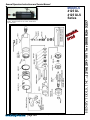
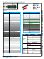
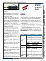
MODELS
4125 GL
4125 GLS
Series
General Safety and Maintenance Manual
Model 4125GL die grinder shown with lightweight aluminum case.
Pre-Year 2009 Original Style model
AL
N
I
IG
OR LE
STY
CAPACITY
Mounted points and carbide
burrs.
4125G Series Die Grinders
Model
Number
Exhaust
Direction
4125GL
Side
4125GLS
Throttle
Type
(L) Lever
or
(K) Safety
Lever
Speed
Power
Output
15000
0.9 H.P.
to
675 W
22000
R.P.M.
(18000RPM
is Standard)
Weight
Case
MateAlumiSteel
rial
num
Steel 1.6 lb/0.7 2.0 lb/0.9
or
Kg
Kg
Aluminum
Length Diameter
5 1/2”
140mm
1.6
inches
41 mm
Air
Consumption
25cfm
11.8 L/S
The Henry Tool Co., Manufactured by Henry Tools
498 So. Belvoir Blvd., South Euclid, OH 44121 U.S.A.
Ph: (216) 291-1011 or (800) 826-5257 ● Fax: (216) 291-5949 or (800) 303-2800
Email: [email protected] ● Website: www.Henrytools.com
Collet Size
1/4”
Model 4125GLSK Die grinder shown with a safety lock
handle. Features a built-in 1/4” collet. Show with a
mounted stone.
MODELS
4125 GL
4125 GLS
Series
L
Ph:
INA
G
I
OR LE
STY
HENRY TOOLS, INC. (216) 291-1011 or (800) 826-5257
General Operators Instructions and Service Manual
www.HenryTools.com | Page 284
For additional product information visit our website.
Revised 02/26/12
Model 4125GLSK Die grinder shown with a safety lock
handle. Features a built-in 1/4” collet. Show with a
mounted stone.
PART
DESCRIPTION
IN
G
I
OR LE
STY
PART
DESCRIPTION
320-9R
O-RING
592016
SNAP RING
320-9W
BEARING COVER
832636
GASKET
400-G-11
FRONT BEARING
841553
3/8 NPT TO 1/4 NPT BUSHING
400-G-14-CS
COLLET SPINDLE
844302
0-RING
400-G 14-CS+3
3” EXTENDED SPINDLE
869311
THROTTLE VALVE CAP
400-G 14-CS+6
6” EXTENDED SPINDLE
WRENCHES
400-G-26
THROTTLE LEVER
1100-044
7/16” WRENCH
400-G-29
THROTTLE VALVE-INCLUDES
844302
1100-063
5/8” Wrench
400-G-34
SPRING
400-S-38
ALUMINUM MOTOR RETAINER
400-S-38-S
STEEL MOTOR RETAINER
400-2G
CYLINDER
400-2GR
REVERSE ROTATION CYLINDER
400-10
KEY
400-3
REAR ENDPLATE
400-39
O-RING
400-3R
REVERSE ROTATION REAR
ENDPLATE(Special)
400-44
ROLL PIN
400-46
SNAP RING
400-5
ROTOR
400-51
0-RING
400-6
BLADE (5 REQ)
400-7
FRONT ENDPLATE
400-9
REAR BEARING
402-126
SAFETY LEVER
402-127
402-128
402-129
SAFETY LEVER SPRING
402-130
ALUMINUM CASE (SPECIFY
SPEED)
402-130-S
STEEL CASE (SPECIFY SPEED)
402-134
MUFFLER SCREEN
410-G-17-S
STEEL SIDE EXHAUST SLEEVE
540129
STEEL MOTOR RETAINER (Same
as 400-S-38-S)
700-37
THROTTLE LEVER PIN
591106
SET SCREW (SPECIFY SPEED)
ASSEMBLIES
510075
REPAIR KIT
402-26
SAFETY LEVER ASSY.
AA-402-130
ALUMINUM CASE ASSY.
AA-402-130-S
STEEL CASE ASSY.
AA-402-130-SK
STEEL SAFETY CASE ASSY.
SPECIFY SPEED FOR CASE ASSY.
REPAIR KITS
510075
CAUSE
SOLUTION
Air pressure too
low
Minimum air pressure should be
90 PSI for maximum performance
Restriction in air
hose
Remove bends or other restrictions
Hose I.D. is too
small
Use required hose I.D.
SAFETY LEVER PIN
Worn vanes
Exchange vanes (400-6)
LOCKOUT LEVER
Screen Support
clogged
Clean screen support or exchange with new one
No air, shut-off
valve is closed.
Open shut-off valve
Machine does
not start
Worn vanes
due to lack of
oil or vanes are
jammed
Exchange vanes . (cylinder might
also be worn out)
Grinder does
not want to
stop
Worn O-Ring
Replace o-ring in handle (844302)
for example.
Spindle
wobbles or
vibrates.
Bearings worn
out .
Danger!!
Disconnect tool from the air
supply. Immediate servicing is
required.
www.HenryTools.com | Page 285
FAULT
REPAIR KIT INCLUDES ALL BEARINGS, ROTOR BLADES and SNAP
RINGS
Insufficient
Power
For additional product information visit our website.
Revised 02/26/12
Ph:
MODELS
4125 GL
4125 GLS
Series
AL
HENRY TOOLS, INC. (216) 291-1011 or (800) 826-5257
General Operators Instructions and Service Manual
Model 4125GLSK Die grinder shown with a safety lock
handle. Features a built-in 1/4” collet. Show with a
mounted stone.
SAFETY
Additional information on safety is available in the
“American National Safety Code for Portable Air
Tools” (ANSI Bl86.1). This bulletin is available from
the American Standards Institute, Inc., 1430 Broadway, New York, N.Y. 10018.
1. Before operation check spindle speed with a
tachometer. If the RPM’s exceed the rated speed
stamped on tool, servicing is required.
2. The 4125 series die grinders are intended for
use with mounted wheels, points and carbide burrs.
They are not guarded for type 1 wheels. If you have
a type 1 wheel application, please purchase another
model tool.
3. At least one-half of the mandrel length (i.e.
mounted wheel, burr, etc.) must be inserted into the
collet. Secure collet chuck tightly.
4. Safety levers (402-26) are available from the
manufacturer Henrytools,Inc..
5. CAUTION: Before mounting or removing a
Mounted point or carbide burr disconnect grinder
from air supply.
6. Wear safety goggles and other protective clothing (when necessary).(See regulations.)
7. Properly maintained air tools are less likely to
fail or cause accidents. If the tool vibrates or produces an unusual sound, repair immediately.
LUBRICATION
1. An air line filter-regulator-lubricator should be
located as closely as possible to the tool.
2. Clean out dirt and moisture fron air hoses daily.
3. Keep screen handle bushing in tool.
N
IGI
R
O LE
STY
and plunger (400-G-29). Remove o-ring (400-G-31) and replace if
cracked or worn.
REASSEMBLY
1. Support front bearing (400-G-ll) on suitable drill block. Press
spindle [400-G-14-CS] through bearing until it bottoms on shoulder.
2. With type 02 pliers place the snap ring (400-46) into the groove.
Slide on front thrust (400-7) over the arbor and on the front bearing.
3. Place the key (400-10) into the slot in the spindle.Slide rotor
(400-5) over spindle, aligning the keyway in the rotor with the key in
spindle.
4. Place five blades (400-6) in slots of rotor. Slip cylinder [4002(G)] over rotor. Install rear thrust[400-3]. (Carefully locate cylinder
in the smaller hole of the rear thrust plate.)
5. Place bearing (400-9) in rear thrust and tap bearing in with a
suitable bearing driver.
6. Place snap ring (592016) on spindle groove. Drop o-ring(3209R) and washer (320-9W) in rear thrust. Place snap ring(400-39) into
groove of endplate (400-3).
7. Slip entire motor assembly in case (402-130(S). Put backhead
in vise and replace exahust sleeve(410-G-17(S)). Replace Lock
nut(540129 or 420-130) and tighten.
CAUTION: CHECK TOOL FOR SPEED WITH TACHOMETER. THE
SPEED STAMPED ON TOOL MUST BE AT OR ABOVE THE ACTUAL
SPEED OF THE TOOL.
FAULT
CAUSE
SOLUTION
Air pressure too
low
Minimum air pressure should be
90 PSI for maximum performance
Restriction in air
hose
Remove bends or other restrictions
Hose I.D. is too
small
Use required hose I.D.
Worn vanes
Exchange vanes (400-6)
Screen Support
clogged
Clean screen support or exchange with new one
No air, shut-off
valve is closed.
Open shut-off valve
Machine does
not start
Worn vanes
due to lack of
oil or vanes are
jammed
Exchange vanes . (cylinder might
also be worn out)
Grinder does
not want to
stop
Worn O-Ring
Replace o-ring in handle (844302)
for example.
Spindle
wobbles or
vibrates.
Bearings worn
out .
Danger!!
Disconnect tool from the air
supply. Immediate servicing is
required.
DISASSEMBLY
1. Caution: Disconnect air supply. Remove collet nut (400-G-38) with 5/8 “ wrench and 7/16”
wrench.
2. Clamp backhead [402-130(S)] in a vise. Using a wrench, unscrew case lock nut(540129 or
420-130). Next replace (400-G-38)on spindle. Grab
collet nut with vise and pull out motor package.
Remove collet nut.
3. Remove snap ring(400-39). Remove wafer
(320-9W) and O-Ring (320-9R). Remove snap ring
(592016).
4. With brass or aluminum jawed vise, grasp the
O.D. of the cylinder(400-2G) and end plate (400-3)
firmly. Use a 3/16” punch and tap spindle out of rear
bearing (400-9), being careful not to drop spindle
assembly when it is free.
5. Remove the rotor (400-5), blades (400-6), key
(400-10) and front thrust plate(400-7) .
6. Remove snap ring (400-46) with type 02 pliers.
Place bearing and spindle assembly (threaded end
down) on suitable drill block. Press spindle through
the bearing with an arbor press.
7. (Optional Step): To check throttle valve. unscrew
plug (869311) and lift out valve spring (400-G-34)
www.HenryTools.com | Page 286
MODELS
4125 GL
4125 GLS
Series
Insufficient
Power
For additional product information visit our website.
Revised 02/26/12
Ph:
AL
HENRY TOOLS, INC. (216) 291-1011 or (800) 826-5257
General Operators Instructions and Service Manual