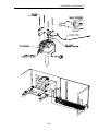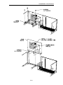
1
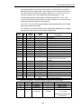
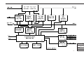
ZOLL Base Powercharger 4x4 Service Manual 9650-0072-01 Rev. E GENERAL INFORMATION SECTION I GENERAL INFORMATION TABLE OF CONTENTS DESCRIPTION SECTION I. General Information • Table of Contents .............................................................................I-1 • Safety Considerations ......................................................................I-3 • How to Use This Manual ..................................................................I-5 • Symbols used on the Equipment......................................................I-7 • Service Policy ...................................................................................I-8 II. Checkout Procedures • • • • Leakage Current Test......................................................................II-2 Functional Tests ..............................................................................II-2 Manual Test.....................................................................................II-3 Checkout Procedure........................................................................II-4 III. Troubleshooting Guides • TroubleShooting Table ...................................................................III-2 • Fault Codes Table ..........................................................................III-3 • Definition of Fault Code..................................................................III-4 IV. Functional Descriptions • System........................................................................................... IV-2 • Common Circuitry Description....................................................... IV-3 • Bay Circuitry Description ............................................................... IV-5 • LED PCB ..................................................................................... IV-12 V. Schematic Drawings • Display / Keyboard. ........................................................................ V-3 • System............................................................................................ V-4 VI. Component Layout Drawings • LED................................................................................................ VI-3 • System .......................................................................................... VI-4 I-1 GENERAL INFORMATION VII. Disassembly Procedures • Removing the Base Pan................................................................ VI-3 • Removing the Main PCB Assembly ............................................. VI-5 • Removing the Heat Sink................................................................ VI-7 • Removing the Transformer............................................................ VI-9 • Removing the Power Entry Module............................................. VI-12 • Removing the Battery Harness and Contact Pins....................... VI-14 VIII. Replacement Parts • APPENDIX A Field Replaceable Units .............................................................. VIII-2 OPERATOR'S MANUAL I-2 GENERAL INFORMATION SAFETY CONSIDERATIONS WARNINGS General • The following is a list of service related safety considerations. For operation related safety considerations see the Base PowerCharger4x4 Operator's Guide. Service Technicians should be aware of all safety considerations prior to servicing the equipment. • THE BASE POWERCHARGER4x4 DEVICE SHOULD BE SERVICED BY QUALIFIED PERSONNEL ONLY! Unauthorized persons should not attempt to service this device. • The Base PowerCharger 4x4 is protected against interference from radio frequency emissions typical of two-way radios used in emergency service/public safety activities. Users of the Base PowerCharger 4x4 should assess the devices’ performance in their environment of use for the possibility of radio frequency interference from high-power sources. • Use only the AC power line cord supplied with the device. Failure to use the proper line cord could result in excess leakage currents and reduced safety. • Only Qualified Personnel should disassemble the PowerCharger 4x4. A shock hazard exists. Refer all problems to ZOLL Technical Service. • Follow all recommended maintenance instructions. If a problem occurs, obtain service immediately. Do not use the Base PowerCharger 4x4 until the unit has been inspected by the appropriate personnel. • Do not place anything on top of the Base PowerCharger 4x4. Doing so may block the vents on the unit, preventing proper dissipation of heat during operation. • Do not sterilize the Base PowerCharger 4x4. • Do not use alcohol or ketones (MEK, acetone, etc.) on the Base PowerCharger 4x4. • Always wait until the Base PowerCharger 4x4 has completed its charge cycle before removing batteries. • Repeated use of partially charged batteries will reduce their capacity and operating life. I-3 GENERAL INFORMATION Operator Safety • Do not operate the Base PowerCharger 4x4 in the presence of flammable agents (such as gasoline), oxygen-rich atmospheres, or flammable anesthetics. Using the device near the site of a gasoline spill may cause an explosion. • Do not immerse or set the Base PowerCharger 4x4 in fluid. Using the device near or within puddles of water is a shock hazard to the operator, patient, and nearby personnel. Patient Safety • Do not mount the device directly above the patient. Locate the Base PowerCharger 4x4 and ZOLL resuscitation devices where they cannot harm the patient if they fall. Caution • Do not discharge a PD 4410 battery pack except in a Base PowerCharger4x4 or compatible ZOLL Battery Charging/Testing device. • Safety and effectiveness data submitted to the Food and Drug Administration (FDA) under section 510(K) of the Medical Device Act by ZOLL Medical Corporation to obtain approval to market is based upon the use of ZOLL accessories such as disposable electrodes, patient cables and batteries. ZOLL cannot make representations as to safety and clinical effectiveness when a device is used with nonZOLL accessories. Users assume all responsibility for the safety and effectiveness of ZOLL products if used with non-ZOLL accessories. Further, ZOLL disclaims all implied and expressed warranties, including warranties of fitness and merchantability, and all product liability to the extent possible in the event of the use of a non-ZOLL accessory. • The equipment may only be used with disposables, accessories, and consumable items when an agency, accredited for the testing of the equipment, has established that those items, in their intended use, meet its safety requirements. I-4 GENERAL INFORMATION HOW TO USE THIS MANUAL Who it is for The Base PowerCharger 4x4 Service Manual is a basic technical reference document designed for biomedical engineering personnel whose responsibilities include maintenance and repair of medical equipment. Purpose Its purpose is to provide the basic information needed to allow biomedical engineering personnel to identify and/or repair the Base PowerCharger 4x4 to the sub-assembly (printed circuit board) level. Recommended Use The Service Manual should be readily available in the facility's equipment maintenance library. It will be used for preventive maintenance checks and for troubleshooting when problems are reported. The Operator's Guide, included as Appendix A, will be used in training new operators and for operational reference. This copy should be kept with the Base PowerCharger4X4 Service Manual. A separately bound copy should be kept with the Base PowerCharger4X4 device. The Service Manual consists of several key sections: Section I: General Information This section contains a number of important notices and reference material, including safety warnings and ZOLL's warranty statement. Be sure to review this section thoroughly before attempting to use or service the Base PowerCharger 4x4 device. Section II: Checkout Procedures This section contains information you need in order to verify that the Base PowerCharger4X4 is functioning properly, and procedures for checking the Base PowerCharger4X4. For daily inspection and operational checks, see the Operator's Manual. Section III: Troubleshooting Guides This section contains an operational troubleshooting section, for use by non-technical personnel to respond to common problems detected during Base PowerCharger4X4 operational use. Section IV: Functional Descriptions This section provides a basic technical description of the Base PowerCharger4X4 main subassembly modules. The information should be thoroughly reviewed before servicing. Section V: Schematic Drawings Major circuit board schematics are included for troubleshooting purposes. I-5 GENERAL INFORMATION Section VI: Component Layout Drawings Major component layout drawings are included for troubleshooting purposes. Section VII: Disassembly Procedures Step-by-step instructions are provided for removing subassemblies in the event of failure. Refer to the Service Policy in Section I for return and repair information. Section VIII: Replacement Parts This section contains a detailed listing of ZOLL part numbers for field replaceable parts available for the Base PowerCharger 4x4 and will allow the service person to identify and order replacement parts. No attempt to replace parts at the component level should be attempted or the ZOLL warranty may be voided. Appendix A: Operation The Operator's Manual has been reproduced here for convenience and consistency. It should be read and understood before attempting any service procedure. I-6 GENERAL INFORMATION SEE FILE PG7_C.PM5 FOR THIS PAGE AND ALL OF THE SYMBOLS I-7 GENERAL INFORMATION SERVICE POLICY WARRANTY In North America: Consult your purchasing agreement for terms and conditions associated with your warranty. Outside of North America: Consult ZOLL authorized representative. In order to maintain this warranty, the instructions and procedures contained in this manual must be strictly followed. For additional information, please call the ZOLL Technical Service Department at 1-800-348-9011 in North America 1-781-229-0020 outside of North America SERVICE The Base PowerCharger4X4 will provide trouble free operation without periodic recalibration or adjustment. However, it is recommended that the biomedical engineering department perform routine tests of the device to verify proper operation. (See Section II.) U.S.A. customers Should the Base PowerCharger4X4 require service, contact the ZOLL Technical Service Department to obtain a return claim number. The unit should be returned, in its original container, to: ZOLL Medical Corporation 32 Second Avenue, Burlington, Massachusetts 01803-4420, Attn: Technical Service Department Loaner instruments are available for use while repairs are being completed. To request loan equipment, contact ZOLL at 1-800-348-9011 (in Massachusetts: 1-781-229-0020). Please have the following information available to expedite service: • Unit serial number • A description of the problem • Department where equipment is in use • A Purchase Order to allow tracking of loan equipment • A Purchase Order for systems out of warranty I-8 GENERAL INFORMATION International Customers Should the Base PowerCharger4X4 require service, it should be returned, in its original container, to the nearest authorized ZOLL Medical Corporation service center. To determine which authorized ZOLL Medical Corporation service center to use, write, call or fax: ZOLL Medical Corporation 32 Second Avenue, Burlington, Massachusetts 01803-4420, USA Attn: International Sales Department 1-781-229-0020 (voice) or 1-781-272-5443 (fax) Attn: International Sales Department I-9 GENERAL INFORMATION I-10 CHECKOUT PROCEDURES SECTION II CHECKOUT PROCEDURES ZOLL recommends that you check your Base PowerCharger4x4 for proper operation at least once every six months. This section contains information you need in order to verify that the Base PowerCharger4x4 is functioning properly. Daily operational checks are described in Section 3, Maintenance and TroubleShooting in the Operator's Guide. TABLE OF CONTENTS 1. Leakage Current Test......................................................................................................II-2 2. Functional Test ...............................................................................................................II-2 9650-0072 II-1 Rev. D CHECKOUT PROCEDURES 9650-0072 II-2 Rev. D CHECKOUT PROCEDURES LEAKAGE CURRENT • Perform Leakage Current Test per your manufacturer's recommended procedure found in the Operator's Manual of your Leakage Tester. Observe: • After the test is complete, fill in the date , operator, and Base PowerCharger4x4 serial number on the Test Data Sheet (Page II-4). Review the results against the limits below for any test that failed. If any test fails, circle the failed test on the Test Data Sheet and take corrective action. • Record results on Test Data Sheet (Page II-4). TEST 90 - 265 VAC LIMITS Gnd Wire Resistance N/A Line Voltage Hot to Neutral N/A Hot to Gnd N/A Neutral to Gnd N/A Current Consumption N/A Chassis Leakage Normal Pol. w/Ground < 500 µA Normal Pol. No/Ground < 500 µA Reverse Pol. No/Ground < 500 µA Reverse Pol. w/Ground < 500 µA Ground Wire Leakage Normal Pol. No/Ground < 500 µA Reverse Pol. No/Ground < 500 µA FUNCTIONAL TESTS Continuity and Isolation Test 9650-0072 • Take a measurement of the Digital Volt Meter (in ohms) by shorting the two (2) leads of the DVM. • Record Results on Test Data Sheet (Page II-4). • Place the red lead of the DVM on any part of the unit where there is exposed metal, except for the battery terminals, and place the black lead of the DVM on the ground part of the powercord. • Record Results on Test Data Sheet (Page II-4). • Subtract the two values and the difference should be less than 1 ohm. II-3 Rev. D CHECKOUT PROCEDURES • Record Results on Test Data Sheet (Page II-4). MANUAL TEST • Check to see that the unit is connected to live AC mains. The POWER light should be lit. • Remove all batteries from the Base PowerCharger4x4. • Press each of the four (4) TEST buttons corresponding to each of the four (4) battery compartments. • The unit will light all of the LED's associated with the compartment for a few seconds. This will be followed by a beep and then the TESTING and BATT. READY LED's will light for a couple of seconds. Then all LED's extinguish. • • Ensure that all of the FAULT indicators are off. If any of the FAULT lights are lit, the compartment is defective in some way. To identify the defect press and hold the TEST button. Illumination of specific indicator lights together represent a specific defect. (Refer to FAULT CODES TABLE on page III-3 to identify the fault and take corrective action). NOTE: The device under test should be at operating temperature before checking/adjusting voltages. (Device powered up for a minimum of 20 minutes). • • • • • Set the DVM to VOLTS DC. Test each battery compartment seperately by placing the Black lead of the DVM on the left battery contact pin of the battery compartment and place the RED lead of the DVM on the shrouded (middle) pin of the same battery compartment. The voltage measurement on the DVM should be 11.86 ± 0.10 VDC. Record Results on Test Data Sheet (Page II-4). If the voltage measurement is NOT 11.86 ± 0.10 VDC, adjust RV1 (on 93010147) until the correct value is displayed. AUTO TEST OPTION • Install battery into any well and observe that the CHARGER ON and TESTING LED’s are illuminated. NOTE: The CHARGER ON and TESTING LED’s may go off within minutes, depending on the charge state of the battery pack installed. (i.e., Fully Charged) QUICK CHARGE OPTION 9650-0072 • Install battery into any well and observe that the CHARGER ON LED remains illuminated until the battery is “READY”. • The TESTING LED will not turn on by installing a battery into the charger. II-4 Rev. D CHECKOUT PROCEDURES BASE POWERCHARGER4X4 DEVICE CHECKOUT PROCEDURE DATA SHEET S/N___________ OPERATOR___________ DATE_________ COPY THIS FORM BEFORE USING SECTION 1. LEAKAGE TEST Perform this Action: Limits: Circle the Result: 1.1 Chassis Leakage Normal Pol. w/ Ground Normal Pol. No/ Ground Reverse Pol. No/ Ground Reverse Pol. w/ Ground < 500 µA < 500 µA < 500 µA < 500 µA YES or NO YES or NO YES or NO YES or NO 1.2 Ground Wire Leakage Normal Pol. No/ Ground Reverse Pol. No/ Ground < 500 µA < 100 µA YES or NO YES or NO SECTION 2. Perform this Action: 9650-0072 FUNCTIONAL TEST Look for : II-5 Circle the Result: Rev. D CHECKOUT PROCEDURES 2.1 Continuity and Isolation Resistance measurement of two (2) leads shorted to one another. Resistance measurement with Red lead on metal and Black lead on powercord ground. Subtract the two values above. Record value: ________ohms Record value: ________ohms YES or NO Difference should be < 1 ohm SECTION 3. Perform this Action: MANUAL TEST Look for : 3.1 Remove all batteries from the Base PowerCharger Press each battery compartment TEST button (4). Circle the Result: YES or NO 4x4 Set DVM to VOLTS DC. Test each battery compartment All LED's illuminate momentarily, the Batt. Ready and Testing light illuminate alone and then, all LED's go off. Ensure FAULT indicators are all off. YES or NO YES or NO YES or NO Voltage is 11.86 ± 0.10 VDC SECTION 4. YES or NO AUTO TEST For 4 x4 base chargers that are configured as auto test units. Perform this Action: 4.1 Install Battery into any well . 9650-0072 Look for : Circle the Result: Charger on and testing LED’S illuminate. YES or NO II-6 Rev. D TROUBLESHOOTING GUIDES SECTION III TROUBLESHOOTING This section answers many of the common problems or questions that arise during operation. If trouble persists after consulting this guide, contact the appropriate technical personnel or ZOLL Technical Service Department. TABLE OF CONTENTS 1. TroubleShooting Table.................................................................................................. III-2 2. Fault Codes Table .......................................................................................................... III-3 3. Definition of Fault Codes .............................................................................................. III-4 III-1 TROUBLESHOOTING GUIDES TROUBLESHOOTING TABLE Symptoms POWER light does not illuminate. TroubleShooting Method and Possible Causes • • • • CHARGER ON indicator light does not illuminate when battery is inserted into compartment. • • • • • TESTING light does not illuminate when TEST button is pressed. • • • Battery fails test cycle. (FAULT light illuminates with TESTING light). • • • Check that the unit is plugged into an appropriate power source. Check for defective power cord. Plug unit into another power source. Check for blown fuse. Disconnect power cord and open fuse holder to check fuses. Check that the battery is properly seated in battery compartment. Check that battery contacts are clean and not damaged. Check that unit is plugged into an appropriate power source. Test the battery compartment for functionality. Place another battery in the compartment. Check that the battery is properly seated in compartment. Check that unit is plugged into an appropriate power source. Remove the battery and press the TEST button to perform a compartment self-test. If it does not self-test the button is defective. Verify that the battery compartment is fully operational with no defects. Press and hold the TEST button to determine the fault code. (See Fault Codes Table on Page III-3). If all FAULT LED's are on most likely there is a failure in the common circuitry. When the unit does not follow the Power-Up sequence explained elsewhere in this manual or if a fault light comes on at any time follow the steps listed below to identify the fault. Note: The unit can be run through it 's self-test at any time, as long as there is no battery installed, by pressing the TEST button. When the self-test is invoked on a single battery compartment the unit will respond by lighting all the LED's associated with the compartment for a few seconds. This will be followed by a beep and then the TESTING and BATT. READY LED's will light for a couple of seconds. Then all LED's extinguish. Faults that may endanger the reliable charging of a battery or the ability to charge/test successfully are latching faults that can only be cleared by power cycling after the fault is fixed. All other faults are self-clearing as soon as the fault condition is removed. III-2 TROUBLESHOOTING GUIDES Fault Codes Table When the FAULT indicator light illuminates, press and hold the TEST button. The illumination of the following indicator lights together represent a specific defect identified under the Fault Code column. Charger On Batt. Ready Fault Testing Fault Code ON OFF OFF OFF Constant Current Voltage ON ON OFF OFF Discharge ON ON ON OFF Discharge Time ON ON ON ON OverCharge ON ON OFF ON Temperature ON OFF ON ON Low Battery Voltage ON OFF ON OFF High Constant Current ON OFF OFF ON Shutdown OFF ON ON ON High Battery Voltage OFF OFF ON ON Battery Capacity OFF OFF OFF ON Charger OFF ON OFF OFF Constant Voltage OFF ON OFF ON Vcc Voltage OFF ON ON OFF Low Power Supply Voltage OFF OFF ON OFF Low Constant Current NOTE: A battery that has failed a capacity test will display the TESTING & FAULT LED's simultaneously. When the TEST button is pressed and held the LED pattern will not change. This is a normal operating condition and does not reflect a fault with the unit. III-3 TROUBLESHOOTING GUIDES Definition of Fault Codes Constant Current The Constant Current compliance Voltage is below the specified Voltage: range. Discharge: Test discharge has been ineffective. Discharge Time: The unit is unable to perform the discharge test. OverCharge: The total delivered charge exceeds the specified range. Temperature: Internal charger temperature deviated from specified range. Low Battery Voltage: The Battery Voltage measured was below specified range. VCC Voltage: The internal five (5) volt supply deviated from specified range. High Constant Current: The amount of current during a charge was above specified range. Shutdown: Safety shutdown (#2) is not operating properly (shutdown). High Battery Voltage: The Battery Voltage was measured to be above the specified range. Battery Capacity: The battery's capacity was measured to be below the specified range. Charger: Safety shutdown (#1) is not operating properly (charge enable). Constant Voltage: The Constant Voltage deviated from the specified range. Low Power Supply Voltage: The charging voltage was measured to be below the specified range. Low Constant Current: The amount of current during a charge was below specified range. III-4 FUNCTIONAL DESCRIPTION SECTION IV FUNCTIONAL DESCRIPTIONS This section describes the basic operation of the circuits and supplements the troubleshooting guides in Section III of this manual. For additional information, refer to the associated schematics found in Section V. TABLE OF CONTENTS 1. System. ........................................................................................................................... IV-2 2. Common Circuitry Description..................................................................................... IV-3 3. Compartment Circuitry Description ............................................................................. IV-5 4. LED PCB ....................................................................................................................... IV-12 IV-1 FUNCTIONAL DESCRIPTION 1. SYSTEM NOTE: Any reference to PD 1400 includes PD 1400, D 1400, PD 2000, D 2000, and ZOLL 1600 unless otherwise specified Product Overview The ZOLL Base PowerCharger 4x4 (with QuickCharge or AutoTest) is a battery charger and testing system designed for management of PD 4410 battery packs used in ZOLL Medical Corporation resuscitation devices. The ZOLL Base PowerCharger 4x4 (with QuickCharge or AutoTest) provides four battery charging/testing compartments. Up to four battery packs may be charged or tested in any combination at one time. The ZOLL Base PowerCharger 4x4 can be configured in either the AutoTest or QuickCharge mode. This configuration is performed by ZOLL Medical Corporation prior to device shipment. The Base PowerCharger4x4 is clearly labeled AutoTest or QuickCharge on the charger label directly beneath the product name. If the device is not labeled, the QuickCharge instructions should be followed for proper device operation. For questions concerning the chargers configuration please consult a ZOLL technical service representative. AutoTest The ZOLL Base PowerCharger 4x4 with AutoTest automatically tests battery capacity with each battery recharge. In addition, the ZOLL Base PowerCharger 4x4 with AutoTest illuminates the Batt. Ready indicator when the battery is fully charged and capable of powering a PD 1400/D 1400 or PD 2000/D 2000 for approximately 2.0 hours in Monitor mode*. Fully charged batteries whose capacity is insufficient to power the devices for this period of time will cause the FAULT light to illuminate. With AutoTest, the full charging cycle is complete in eight (8) hours or less. The AutoTest feature virtually eliminates the need to periodically test battery capacity since this test is performed each time a battery is recharged. QuickCharge The ZOLL Base PowerCharger 4x4 with QuickCharge illuminates the Batt. Ready indicator when the battery is fully charged. The full charging cycle is complete in four (4) hours or less. The QuickCharge version provides no information regarding battery capacity because it does not test the battery capacity with each recharge. The ZOLL Base PowerCharger 4x4 with QuickCharge relies on the user to manually initiate the battery test cycle at recommended intervals (see Manual Battery Testing Procedure) in order to confirm adequate battery capacity. Note: Actual battery run time will vary from model to model depending upon the amount of current that is drawn by each device. Refer to the Operator's Manual of your model to determine the actual battery run time. For example, a battery contains at least 1.5 ampere hours, while a ZOLL Defibrillator may draw approximately .8 ampere of current. The run time of the battery is calculated by dividing the battery capacity by the current drawn. In this example, there is a minimum of 1.875 hours of battery run time for this device. IV-2 FUNCTIONAL DESCRIPTION Standard Terms and Abbreviations CV Constant Voltage. Term applies to the type of charging technique used to charge a battery where a Constant Voltage is applied to the battery. CC Constant Current. Term applies to the type of charging technique used to charge a battery where a Constant Current is applied to the battery. Main PCB Refers to the electronics assembly which controls the voltage and current being supplied to the Battery Pack (PD4410). Embedded Processor A software programmable device used to sense and process a series of input signals to produce control/status output signals. LED Light Emitting Diode. Microprocessor A software programmable device used to sense and process a series of input signals to produce control/status output signals. mS Milliseconds. PCB Printed circuit board. PD1400 This term refers to the any of the PD1400/1600/2000 Pacemaker/ Defibrillator family of products that are compatible with the Base PowerCharger4x4. µS Microseconds. 2. COMMON CIRCUITRY DESCRIPTION As shown in the attached Block Diagram each charger compartment operates independently from the others except that all four compartments share a common DC power bus, VCC power supply, voltage references and temperature measurement circuitry. The occurrence of a fault condition in one of the common circuit areas may cause all four charging compartments to suspend operation. In the following sections there will be periodic reference to a device's reference designation and pin number. For example, U3.5 will refer to pin number 5 of device U3. This information is to be associated with the attached system diagram and schematic set. In a similar fashion there will be reference to the microprocessor's port designation. For example, P3.1 will refer to the microprocessor's bit 1 of I/O port 3. Refer to the 8051 Data Handbook for a detailed description of the 87C752 I/O port capabilities and other features. IV-3 FUNCTIONAL DESCRIPTION DC Power Bus Circuitry All four charging compartments share an unregulated 30V DC Power Bus which is used by each compartment as the power source for its switching power supply control circuit. This DC bus is created from a 24Vac input which originates from a chassis mounted transformer and enters the board via 2 pin connector J3. This AC input is rectified by bridge BR1 and filtered by capacitors C133, C233, C333 and C433. Any transients from the line which are not eliminated by the filter capacitors are absorbed by the metal oxide varistor TV1. JP8, R42, R43, R44, and D11 dissipate energy stored on the caps when AC is turned off. JP8 allows this dissipation circuit to be disabled. +12Vdc Supply U3 with R7 and R8 provide a regulated 12 volts used to operate the alarm. C1 provides RF bypassing. C2 is a voltage filter capacitor. D1 is a reverse current protection diode. JP7 provides the user with the ability to select where the raw voltage comes from for the alarm. Logic Power Supply A +5V +/- .25V power supply is produced from the +24Vac input (originating from connector J3) to power the analog and digital circuitry on the board. D4 and D5 along with C8, R9, and C3 rectify and filter this AC input voltage providing an unregulated 30Vdc input voltage for the fixed +5V output switching regulator U4. U4 along with D3, L1, C5, C6, C7 and R11 are implemented in a "buck" configuration. D2 provides a final over voltage protection for the logic supplies. For more details on "buck" converter operation see Switchmode Power Supply section. Reference Voltages A two terminal, 1.235V band gap reference (U9) is used to create all of the reference voltages that are routed to the charging compartments. U9 is biased by R27 and buffered by amplifier U8B. C25 is an RF filter capacitor. A second temperature compensated reference is created from device U9 to set the constant voltage mode output of each charger compartment. The positive input of amplifier U8A is referenced to the sum of U9 and the voltage across signal diode D10. Resistors R25, R26, R28 and potentiometer RV1 set the nominal gain of the amplifier to a range of 1.48 - 1.72. C24 and C27 provide RF filtering. C23 provides power supply filtering and bypassing. The voltage developed across the silicon diode varies inversely to ambient temperature. This diode characteristic causes the reference circuit to automatically adjust the CV charge voltage down as temperature rises which is in accordance with the recommendations of the lead-acid battery manufacturer. Amplifier U6A, along with gain resistors R22 and R23, are used to create a third 3.3V reference voltage. C18 and C19 provide RF filtering. C20 provides power supply bypass and filtering. This reference voltage is bussed to an A/D input of each charger compartment's microprocessor and used to verify the accuracy of the VCC supply voltage (refer to VCC Test Circuitry Section for more details). This self-test feature insures that all A/D readings are accurate and not corrupted by a faulty VCC supply voltage. IV-4 FUNCTIONAL DESCRIPTION Temperature Measurement Circuitry Temperature measurement circuitry is provided in order to compensate for battery charge and capacity test variations due to temperature. The signal generated by voltage divider RT1 and R24 is buffered by amplifier U6B and routed to an A/D input of each microprocessor through R135, R235, R335, and R435 for isolation. C22 and C21 provide RF filtering. Since thermistor RT1 has a nominal value of 10K at 25oC, the output voltage at room temperature will be 2.5V (midrange on the microprocessor A/D). With an 8 bit converter on each microprocessor, the system's internal ambient temperature can be determined within the range 0 - 70oC with 5% accuracy and 1oC resolution. Temperature compensation is based on ambient, not battery temperature. Alarm Circuitry U1A and R1, R2 and Q1 provide the control mechanism for turning the alarm (LS1) on from the alarm ports located on each compartment microprocessor. Battery Detection Circuitry A set of battery detection circuits, comprised of differential amplifiers U5A U5B, U5C and U5D and associated components, signals each microprocessor if a battery is installed into its charging compartment. The input signal for each circuit is the battery sense lead which enters the board, along with the battery positive and negative terminals, via connector J1. A resistor divider (R13/R14, R15/R16, etc.,.) is used for each battery detect op amp input to keep the working voltage range within the VCC supply voltage. Each op amp within U5 is configured as a comparator with a 1.2V threshold reference presented to the negative input pin. Diodes D6 through D9 protect each amplifier from static discharge and C9, C11, C15, and C17 are used as filter capacitors. C10, C12, C14, and C16 are RF filtering capacitors. Each charging compartment's microprocessor observes its battery detection signal at port P1.7 (U104.22) with a positive voltage signifying the presence of a battery. 3. COMPARTMENT CIRCUITRY DESCRIPTION The following section describes the electronics that are common to all four charger compartments. A block diagram overview of compartment circuitry is attached. For simplicity, all part designators will be referenced to the first compartment only. All of the reference designators for the other three compartments are exact increments of 100 in relation to charging compartment 1's values. The reference designators for the microprocessor, for example, is U104, U204, U304 and U404 for charging compartment 1, 2, 3 and 4 respectively. All reference designators below 100 are associated with common circuitry. Microprocessor Each charging compartment contains a microprocessor that controls charging, discharging and capacity testing of the compartment's battery. The microprocessor also monitors battery voltage, battery current, system ambient temperature and the system power supply to determine if any fault condition has occurred. Four status LED's and a test switch are also controlled by the microprocessor. IV-5 FUNCTIONAL DESCRIPTION The microprocessor (U104) is a 87C752 running at 6.144 MHz with 16K of internal ROM and 64 bytes of internal RAM. It also includes a five bit I/O port (port #0; pins 6 8, 23 and 24) and two 8 bit I/O ports (port #1 and #3; pins 13 - 22 and 1- 5, 25 - 27). The lower five bits of port 1 are configured as analog inputs (pins 13 - 19). The operating frequency is derived from the external crystal circuit (Y101, C103, C102, R114) connected to the processor (at U104.10 and U104.11). R124 and C123 provide the reference voltage for the internal A/D. C112, C101, C129, C130 are bypass capacitors associated with various IC's located within each compartment circuitry. For a summary of the microprocessor I/O pin assignments and Battery Test, Charging Voltage and Current Settings see the following tables below. Port & Pin P0.0 P0.1 P0.2 P0.3 P0.4 P1.0 P1.1 P1.2 P1.3 P1.4 P1.5 P1.6 In / Out ---O O I I I I I -I Analog /Digital D D D D D A A A A A D D Signal Name ---WDO CAPOUT V_BATT V_TST TEMP I_SENSE FREQ -TEST- P1.7 P3.0 P3.1 P3.2 P3.3 P3.4 P3.5 P3.6 I O O O O O O O D D D D D D D D BAT_DET+ CHRG_LED+ RDY_LED+ TST_LED+ FALT_LED+ SHUTDWN+ CHRG_ENBSSEL0- P3.7 O D SSEL1- Description - Not Used - Not Used - Not Used Watchdog output. PWM Capacity Level Indicator Battery Voltage VCC Test. Temperature Current Sense Clock Test - Not Used Enable support diagnostics (not available in all versions of code release). Battery Detection. Charge LED Ready LED Test LED Fault LED. Charge Shutdown Charge control circuit enable. Charge state select bit 0. Charge state select bit 1. Summary of the Battery Test and Charging Voltage and Current Settings; SSEL0SSEL1Control State I Limit V Set 1 1 Discharge -Battery voltage 0 1 Discharge -Battery voltage 1 0 CC Charge 0.500 Amps 16.5 Volts 0 0 CV Charge 1.0 Amps ~ 11.75 Volts (actual value changes with temperature) IV-6 FUNCTIONAL DESCRIPTION Clock Test Circuitry Clock testing is provided by the R123 and C122 R/C network. As part of its start-up verification sequence the microprocessor drives the port pin low and then releases it to charge up to VCC. After a delay of approximately 110 uS it reads the voltage to determine if it has reached the 2/3 charge point or approximately 3.3 volts. If it perceives the value to be outside acceptable limits it may be because the crystal oscillator circuit (Y101, C103, C102) is out of specification. In this event the microprocessor will revert to a fault condition to prevent improper operation. VCC Test Circuitry A VCC test is provided by the 3.3V voltage reference circuit which was presented in the "Common Circuitry" section. The microprocessor reads the reference value through its A/D port (U104.14). If it perceives the value to be outside acceptable limits it may be because either the VCC power is out of specification or the reference device has failed. In either event the microprocessor will revert to a fault condition to prevent improper operation. A series resistor (R136) is provided in line with the 3.3V reference to insure that if a microprocessor fails within one of the charging compartments that it does not prevent the others from operating. Watchdog Circuit The Watchdog device (U101) provides two functions. First, it acts as a power on reset circuit to insure that the microprocessor is held RESET until the +5 volt VCC power supply is stable. The watchdog timer continues to monitor the power supply and drives RESET high if the VCC supply falls below tolerance (4.62 volts nominal) anytime during normal operation. Secondly, the device will reset the microprocessor if it does not receive a "refresh strobe" at its input pin (U101.7) at least once every 250 milliseconds. If a reset condition occurs, the microprocessor will be held reset for a minimum of 250 mS. Whenever the microprocessor is held reset by the watchdog, the switchmode power supply circuitry is also disabled via diode D103 and R117. As current is sourced through this device, the safety current limiting comparator (U103.13 and U103.14) turns on causing a "shut down" of the power supply output. Refer to Switchmode Power Supply Section for a detailed description of the switchmode power supply control circuitry. Shut Down Control The Watchdog device (U101) as described above has the ability to both disable the microprocessor and shut down power supply operation. The microprocessor also has the ability to shut down power supply operation in the event that a fault condition is detected. This control function is provided via inverter U106 and diode D102 via R117. As described in the previous section, current sourced through the diode causes the safety current limiting comparator (U103.13 and U103.14) to turn on producing a shut down of the power supply output. Power supply shut down also occurs when the battery test load is enabled. IV-7 FUNCTIONAL DESCRIPTION Charge Control Circuitry The microprocessor establishes one of three different voltage and current control settings to support CV and CC battery charging and battery test. The following paragraphs describe the voltage and current control functions in detail. A fail-safe charge enable circuit is provided which requires that the microprocessor is functioning properly before the current and voltage control limits are established. This is accomplished via the circuit built around the NOR gate U107C. During normal operation the microprocessor produces a pulse train (signal CHRG_ENB-) with a frequency of approximately 500 HZ and a pulse width of approximately 10 µS. This signal passes through the DC blocking capacitor C132 where it is buffered and inverted by U107. The output of U107 (U107.8) is rectified by the network comprised of D110, C131 and R140 which charges up to +5V at each pulse. After the voltage across C131 exceeds 2.4 volts both Schmitt triggered gates (U107B and U107D) are enabled. Since the R/C time constant of C131 and R140 is much slower than 500 Hz, the rectified voltage does not have time to drop below the logic high threshold limits of U107.4 and U107.12 before the next pulse occurs. If a failure causes the microprocessor to halt, leaving the CHRG_ENB- signal at either a stable logic high or logic low, R141 will pull both U107C.9 and U107C.10 inputs high. This action causes the mode select gates (U107B and U107D) to be disabled. Diode D111 is provided to prevent the voltage transition which comes through C132 from exceeding the high and low input signal requirements of the CMOS logic (at U107.9 and U107.10). One of two possible voltage and current limiting values are selected via control gate U107A and U107B. The microprocessor asserts SSEL0- low (at U104.26) to select a one amp charge rate (FET Q104 turned off via control gate U107A) and a nominal CV voltage setting of 11.75 volts (FET Q102 turned off via control gate U107A). If the SSEL0- signal is driven high, FETs Q104 and Q102 are turned on to establish a current control setting of 500 mA and a voltage limit of 16.5V by placing shunt resistor R129 across R104 via Q104 and R120 across R119 via Q102. the gate of Q102 is protected by R121 and the gate of Q104 is protected by R130. For a summary of the current limits for each of the two charge select states see table on page IV-6. Diodes D107 provides static discharge protection for the gates of the current and voltage selection FETs (Q104 and Q102). Display Drive Circuitry The four status LEDs; CHARGER ON, BATT. READY, TESTING and FAULT on the LED PCB assembly are controlled by PORT 3 control lines of the microprocessor (U104 pins 2 -5). Each control signal is buffered by both a logic inverter (U106A, U106B, U106C and U106D) and a darlington driver (U7 or U2). A 270 ohm resistor network (RN1 & RN2) limits the LED on current to 15mA. J2 connects all of the LED and test switch control signals to the LED PCB assembly over a ribbon cable. Resistor R17 turns on the 'POWER' LED on the LED PCB when the +5V VCC logic supply powers up. See the Operator's manual for further clarification of the LEDs and their use. IV-8 FUNCTIONAL DESCRIPTION Test Switch Interface Circuitry A simple interface circuit and a single input port line is used to monitor the test switch located on the LED PCB. An internal pull-up resistor in the microprocessor holds the input pin high (port P1.6) until the test switch is pressed causing this signal to short to ground. R134 limits the current into the microprocessor from a possible short circuit and D106 is used as a guard against static discharge. Battery Voltage Sense Circuitry The microprocessor monitors the switchmode power supply output and the battery voltage over a range of 8.5 to 16.5 volts to determine the battery's charge status and if it or the internal control electronics or the power supply has failed. The microprocessor resolves the voltage reading to within 50 millivolts (33mV, 8 bit) in order to support the battery charging algorithm requirements. Op amp U105A forms a basic amplifier circuit with a gain of approximately -0.574 and an offset of 8.01V (established by the resistor combination R111, R112 and R110). Resistors R133 and R132 form a voltage divider to drop the battery voltage by a factor of 6 to keep the signal range within the input requirements of the op amp device (U105A). The resulting output signal (at U105.1), ranging from 0 to 4.85 volts is read by the microprocessor at its analog input (U104.13). Capacitors C111 and C108 provide noise filtering while and capacitors C109 and C110 provide RF interference and static discharge protection. C119 is a power supply bypass capacitor. A/D (voltage)=5-((Battery voltage-8.01)*0.574) Current Sense Circuitry The microprocessor monitors the supply current over a range of approximately 0 to 2 amps to determine the battery's charge status or if a control circuit has failed. The microprocessor resolves a current reading to within 8.3 milliamps in order to support the battery charging control requirements. OP amp U102B forms a basic amplifier circuit with a gain of approximately 24 to amplify the current sense signal through the 100 milliohm resistor (R127). The gain of the circuit is established by resistor values R125 and R126. The resulting output signal (I_SENSE at U102.7), ranging from 0 to 4.85 volts is read by the microprocessor at its analog input (U104.16). Capacitor C120 provides noise filtering while and capacitors C114, C115, and C116 provide RF interference and static discharge protection. R 106 is a balancing resistor in the non-inverting input line to the amplifier. A/D (Current)=Battery Current*2.37 IV-9 FUNCTIONAL DESCRIPTION Switchmode Power Supply Operation At the heart of each compartment is a switchmode power supply which establishes each of the charging configurations for the charging compartment. When a battery is inserted and charging is initiated, the switchmode power supply provides a constant voltage to charge the battery. As the battery charges up and the input current into the battery falls below a predetermined level, the battery charging mode is changed by the microprocessor to a constant current charge until the battery is fully charged. Upon completion of the constant current charge sequence, a timed overcharge is applied to insure that the battery has been fully recharged. U103 is a fixed frequency pulse width modulation control IC that contains the building blocks for the power supply. As shown in Figure 1, U103 is configured in a "buck" orientation with power FET Q103 being the switch shown in the diagram. 30VDC+ BAT+ Q103 L101 D113 GND Figure 1 C124 BAT- Buck Mode Switching Regulator When the switch is closed, current builds through inductor L101 inducing a magnetic field. The amount of energy stored in the inductor depends upon how long the switch is closed. When the switch is opened, current starts to decrease through the inductor. The voltage at the cathode of D113 clamps to -0.4V as the current through the inductor decreases (V = L*di/dt). With catch diode D113 now forward biased, there is a path for the energy stored in the inductor to be transferred to the load. The cycle repeats itself with the "ON" and "OFF" time of the switch determined by a feedback control loop. The PWM control device U103 operates at a 100KHz switching frequency which is determined by the C107 and R118 R/C network. An internal open collector transistor "switch" at U103.9 turns Q103 on through a series gate resistor R138 by pulling one end of R137 to ground. D109 clamps the gate-source voltage of Q103 to acceptable levels and the network consisting of Q105, D108 and R139 speeds up the turn-off time of Q103. There are three error feedback amplifiers that control the "ON" and "OFF" time of the internal switch; two of which are internal to the PWM control device and one control amplifier (U102A) that is external. All three amplifiers are OR'ed together at pin 3 of U103. The internal amplifiers are tied together and brought out to pin 3 of U103 and the external amplifier U102A is diode OR'ed through D101 such that the amplifier that demands minimum "ON" time, dominates control of the loop. Power to the regulator IC is filtered via R115 and C117. IV-10 FUNCTIONAL DESCRIPTION When no battery is present in a charging compartment, the voltage feedback amplifier with inputs at U103.1 and U103.2 dominates control of the loop. The negative input of the amplifier is tied to the temperature compensated reference through R103 for isolation purposes. The positive input of the amplifier senses the power supply output voltage via voltage divider R128 and R119 through R108. The divider is filtered by C127 and C118. R/C network R102 and C106 compensate the amplifier ensuring stable operation. R120 is placed in parallel with R119 via Q102 to change the maximum charging voltage during CV or CC charging. R121 is the gate protection resistor in Q102. During battery charging, the current feedback amplifier U102A dominates control of the loop. The output current of the power supply is measured through sense resistor R127. The sense voltage developed across this resistor is then compared to a fraction of the on board 1.2V reference determined by the voltage divider resistors R104 and R105. The result of this compare function is to limit the output current of the power supply to 1A during CV charging and by placing R129 across R104 to 500mA during CC charging. Capacitor C125 provides stabilization for this control loop. C105 and C113 provide RF filtering and C104 provides power supply bypassing. R 107 is a balance resistor for U102A. A second current feedback amplifier with inputs at U103.13 and U103.14 limits supply current to 2A in the event of a failure of amplifier U102A. Operation of this amplifier is similar to that of U102A with resistor divider R118 and R101 providing a reference voltage to compare against the voltage generated across current sense resistor R127 through R116. C126 stabilizes the amplifier ensuring proper control loop operation. R130 is a series gate protection resistor for Q104. A final level of component failure protection is provided by the 2A pico-fuse F101. Each Compartment output voltage is protected by a transorb from positive to negative terminal TV101. JP101 and a transformer, rather than an inductor, allows the switches to be converted from a Buck regulator to a flyback style. Battery Test Control Circuitry The microprocessor initiates a battery test sequence when it has detected the presence of a battery in the charging compartment and the test switch has been pressed. A fail-safe charge enable circuit is provided which requires that the microprocessor is functioning properly before the test load can be applied to the battery. Refer to the Charge Control Circuitry Section (Page IV-8) for a description of the Charge Enable Control circuitry. Once the Charge Enable control is established, the microprocessor may either charge or discharge the battery to prepare a battery for use or determine its ability to perform under load. To apply the test load, the microprocessor asserts SSEL1- high (at U104.25) which places the load resistor (R3) across the battery via the output of U106.12 through R122 to the transistor Q101. As the load is applied across the battery, the power supply is caused to shut down via the current flow through diode D104. Diodes D105 provides static discharge protection for the gate of the load control FET (Q101). IV-11 FUNCTIONAL DESCRIPTION Battery Capacity Output (optional) Output control line P0.4 (U104.24) is used to develop an analog output that is proportional to the capacity of a battery that has been tested. The microprocessor's port line P0.4 is configured as a pulse width modulated output which is filtered by the R131 and C128 R/C network. The resulting DC voltage is buffered by amplifier U105B and bussed to connector J101.2. R113 is a current limiting resistor inserted for protection against accidental shorts. C121 is an RF bypass capacitor. 4. LED PCB The LED PCB assembly provides the user interface to each of the four charging compartments within the Base PowerCharger4x4 system. A ribbon cable running from J2 of the main PCB to P4 on the LED PCB carries the signals that drive the status LED's and test switches for each charging compartment. Located on this assembly are four test switches; SW1 - SW4 (one for each charging compartment), a power on indicator (LED171 or 172) and four sets of status indicators (LED1 - LED4 for charging compartment 1, LED5 - LED8 for charging compartment 2, LED9 - LED12 for charging compartment 3 and LED13 - LED16 for charging compartment 4). All of the drive and interface electronics for these devices are located on the main PCB and are described in the Display Drive Circuitry section and the Test Switch Interface Circuitry. Power Up Operation At power on, the POWER indicator will turn on. The controller for each channel will perform a series of power-on diagnostics (including a test of the four LED's) and then advance to the appropriate mode based on whether a fault is detected, a battery is present, and the status of the test switch. See Diagnostics Section for a detailed description of the power-on diagnostics. If a fault is detected, the controller will revert to the FAULT Mode. Any power brown-out (< 90VAC) or interruption will cause a charging sequence to be restarted when proper power is re-established. If a test is in progress during a power brown-out or interruption the controller will revert to normal operation when proper power is re-established. Press the TEST button to start the testing cycle again. Turn on Delay The system will delay no more that 10 seconds after power on to allow the battery/power electronics to stabilize and go through a self test. The CHARGER ON indicator will be turned on after the delay, if a battery is present. IV-12 FUNCTIONAL DESCRIPTION Charge Mode In this mode of operation the controller will perform a charging sequence on the battery. The CHARGER ON indicator will be turned on at this time. When the CV/CC charge sequence is completed the CHARGER ON indicator will be turned off and the BATT. READY indicator will be activated. For more information, see the Battery Charging Algorithm section. Battery Test Mode This mode will occur only if the test button is activated and a battery is detected by the controller. The TESTING indicator will be activated whenever the channel is in this test mode. The battery test sequence will be as follows; • First the battery will be fully charged. • Battery charging will then be disabled. • A test load will be presented to the battery. The load is to simulate the load presented by the 1400 Series Devices. This load will be maintained until the battery is depleted. • The capacity will then be calculated (see discussion below). • Finally, the battery will be recharged. If the capacity is determined to be adequate a BATT. READY indicator will be activated after the battery is recharged and the TESTING indicator will remain on. If the capacity is insufficient the TESTING and FAULT indicators will be activated at the end of the capacity test and the battery will be recharged, if possible. To abort this mode the user must either remove the battery or interrupt the AC power. Refer to the Battery Charging Algorithm section. Unit Test Mode This mode occurs only if the test button is activated for two seconds with no battery installed. When a self test is performed all LED's illuminate for a brief period of time and if successful the TESTING and BATT. READY indicator's are turned on for a few seconds or if there is a failure the FAULT LED is turned on and left on. This test will be also run automatically at power up and after a battery is removed. Fault Mode If a fault is identified by the controller the FAULT LED for that channel will light (all other LED's for that channel will be turned off ). If the test button is activated for 2 seconds in this state then one of 15 patterns of the four LED's will be activated to indicate the type of fault. This pattern will remain on only while the key is pressed. This mode will be reset every time a battery is installed or removed and at power up. See the Operator's manual for a description of the fault codes. Idle Mode If the battery is not in place the channel will remain in a standby mode ( all LED's are off except for the AC Power LED). IV-13 FUNCTIONAL DESCRIPTION Battery Charging Algorithm The algorithm used to charge the battery in both the charge and test modes is as follows; • When a battery is installed the controller will begin charging operation in a CV charge mode. At this time a charge timer will be started. • The CV mode will continue until the charge current drops to the constant current charge rate. The controller will then record the length of time "T" required to arrive at this CC charge point. • The controller will then switch to a constant current charging mode and charge the battery at a CC charge rate until the battery's voltage peaks ( i.e. remains constant or begins to drop) during a three minute period. • The controller will then maintain a top off CC charge for a period of time equal to the value T (obtained above) divided by 6. i.e. TimeTOP1 = T / 6 • Upon completion of the top off phase the controller will return to an appropriate mode to maintain a float charge on the battery. The controller will remain in this state until the AC power or the battery is removed. IV-14 FUNCTIONAL DESCRIPTION I/O Signal Summary Pin No. I/O Signal Name 5 I/O B1 + 1 I 9 Definition Comments Battery Charge Pin B1 SENS + Battery Sense I/O B1 - Battery Return 6 I/O B2 + Battery Charge Pin 2 I 10 B2 SENS + Battery Sense I/O B2 - Battery Return 7 I/O B3 + Battery Charge Pin 3 I 11 B3 SENS + Battery Sense I/O B3 - Battery Return 8 I/O B4 + Battery Charge Pin 4 I 12 I/O B4 SENS + Battery Sense B4 - Battery Return Battery #1 detection signal. Battery #2 detection signal. Battery #3 detection signal. Battery #4 detection signal. Diagnostics The following sections describe several types of diagnostics that will be performed by the system to insure product safety and simplify assembly and test requirements. Power Up As AC power is applied, the controller will perform a series of internal tests to determine if the electronics are functional. The following tests are performed ; • Timer Accuracy. Verify that the internal clock/timing function has not shifted fundamental frequency. • Memory Validity. Verify that all of the embedded processor's internal memory locations (RAM and ROM) are functional. • Power Supply Accuracy. Verify that the logic power supply is within tolerance • LED Test. Turn the four LED's on for a short period. If any of the first three functional tests fail, the controller will revert to the Fault mode (see Fault Mode section). It will be left to the user to verify that the LED's are functional. IV-15 FUNCTIONAL DESCRIPTION User Tests This mode occurs only if the test button is activated for two seconds with no battery installed. A self test will be performed which will include turning on all LED's for a brief period of time. If successful, the TESTING and BATT. READY indicator's will be turned on for a few seconds. If a failure is detected, the FAULT indicator will be turned on and left on. This test will also be run automatically after a battery is removed. The following tests will be performed: • Timer Accuracy. Verify that the internal clock/timing function has not shifted fundamental frequency. • Memory Validity. Verify that all of the imbedded processor's internal memory locations (RAM and ROM) are functional. • Power Supply Accuracy. Verify that the logic power supply is within tolerance. • Charger voltage control test. Verify CC and CV voltage levels Run Time Tests The controller will perform a series of internal tests to insure safe operation. Some of these tests will be performed continuously. Other tests will be performed at the appropriate moment of run time operation. A summary follows; • Power Supply accuracy. Verify that the power supply is within tolerance. • OverCharge Timer test. Performed during the CV/CC charge sequence. Limit the amount of time battery is subjected to charge to less than 4 AH. • Battery Voltage validity. Performed during the CC charge sequence. Verify that the battery is within acceptable voltage limits. • Charge Current validity. Performed during the CC charge sequence. Verify that the charge current is within acceptable limits. • Temperature validity. Performed continuously. Verify that the temperature is within acceptable limits. If temperature is too high or too low the controller will disable constant current charging and will turn the FAULT indicator on. • Embedded Processor Operation. Performed continuously. Verify that the processor is properly executing its program. If any of these tests fail, the controller will either be disabled or will revert to the Fault mode. For those faults in which the microprocessor is still functional, CV charge operation will be maintained. Except for a battery voltage failure the microprocessor will continuously attempt fault recovery. In the event of a battery voltage failure the microprocessor will stay in the fault mode until the battery is removed. If the microprocessor is disabled the charge circuitry will revert to CV charge operation and the FAULT indicator will flash to indicate this condition to the user. IV-16 SCHEMATIC DRAWINGS SECTION V SCHEMATIC DRAWINGS ZOLL Base PowerCharger4x4 schematic drawings are included here to supplement the information presented in: • Section III, Troubleshooting • Section IV, Functional Descriptions • Section VI, Component Layout Drawings LIST OF DRAWINGS Description Page 1. Display / Keyboard, PCB ......................................................................... V-3 2. System ..................................................................................................... V-4 V-1 SCHEMATIC DRAWINGS V-2 SCHEMATIC DRAWINGS ZOLL TITLE ZOLL MEDICAL CORPORATION 32 SECOND AVENUE BURLINGTON, MA. 01803 SCHEMATIC, PCB, DISPLAY/ KEYBOARD DWG NO. REV. 9301-0145-SC SHT V-3 1 OF 1 SCALE B NONE SERVICE MANUAL (NOT USED ON BASE POWERCHARGER4X4) ZOLL TITLE ZOLL MEDICAL CORPORATION 32 SECOND AVENUE BURLINGTON, MA. 01803 SCHEMATIC, PCB, SYSTEM, BASE POWERCHARGER4X4 DWG NO. REV. 9301-0147-SC SHT V-4 1 OF 7 SCALE B NONE SCHEMATIC DRAWINGS ZOLL TITLE ZOLL MEDICAL CORPORATION 32 SECOND AVENUE BURLINGTON, MA. 01803 SCHEMATIC, PCB, SYSTEM, BASE POWERCHARGER4X4 DWG NO. REV. 9301-0147-SC SHT V-5 2 OF 7 SCALE B NONE SERVICE MANUAL ZOLL TITLE ZOLL MEDICAL CORPORATION 32 SECOND AVENUE BURLINGTON, MA. 01803 SCHEMATIC, PCB, SYSTEM, BASE POWERCHARGER4X4 DWG NO. REV. 9301-0147-SC SHT V-6 3 OF 7 SCALE B NONE SCHEMATIC DRAWINGS NOTES: 1. ALL RESISTORS ARE 1% TOLERANCE UNLESS OTHERWISE SPECIFIED. 2. ALL CAPACITOR VALUES ARE IN MICROFARADS UNLESS OTHERWISE SPECIFIED. ZOLL TITLE ZOLL MEDICAL CORPORATION 32 SECOND AVENUE BURLINGTON, MA. 01803 SCHEMATIC, PCB, SYSTEM, BASE POWERCHARGER4X4 DWG NO. REV. 9301-0147-SC SHT V-7 4 OF 7 SCALE B NONE SERVICE MANUAL ZOLL TITLE ZOLL MEDICAL CORPORATION 32 SECOND AVENUE BURLINGTON, MA. 01803 SCHEMATIC, PCB, SYSTEM, BASE POWERCHARGER4X4 DWG NO. REV. 9301-0147-SC SHT V-8 5 OF 7 SCALE B NONE SCHEMATIC DRAWINGS ZOLL TITLE ZOLL MEDICAL CORPORATION 32 SECOND AVENUE BURLINGTON, MA. 01803 SCHEMATIC, PCB, SYSTEM, BASE POWERCHARGER4X4 DWG NO. REV. 9301-0147-SC SHT V-9 6 OF 7 SCALE B NONE SERVICE MANUAL ZOLL TITLE ZOLL MEDICAL CORPORATION 32 SECOND AVENUE BURLINGTON, MA. 01803 SCHEMATIC, PCB, SYSTEM, BASE POWERCHARGER4X4 DWG NO. REV. 9301-0147-SC SHT V-10 7 OF 7 SCALE B NONE COMPONENT LAYOUT DRAWINGS SECTION VI COMPONENT LAYOUT DRAWINGS ZOLL Base PowerCharger4x4 component layout drawings are included here to supplement the information presented in: • Section III, Troubleshooting • Section IV, Functional Descriptions • Section V, Schematic Drawings LIST OF DRAWINGS Description Page 1. LED, PCB, Base PowerCharger 4x4 .........................................................VI-3 2. System .....................................................................................................VI-4 VI-1 COMPONENT LAYOUT DRAWINGS VI-2 COMPONENT LAYOUT DRAWINGS ZOLL ZOLL MEDICAL CORPORATION 32 SECOND AVENUE BURLINGTON, MA. 01803 TITLE ASSY DWG, PCB, LED, BASE POWERCHARGER4X4 DWG NO. REV. 9301-0145-AD SHT VI-3 1 OF 1 SCALE B NONE SERVICE MANUAL ZOLL TITLE ZOLL MEDICAL CORPORATION 32 SECOND AVENUE BURLINGTON, MA. 01803 ASSY DWG, PCB, SYSTEM, BASE POWERCHARGER4X4 DWG NO. REV. 9301-0147-AD SHT VI-4 1 OF 1 SCALE A NONE DISASSEMBLY PROCEDURES SECTION VII DISASSEMBLY PROCEDURES This section is designed to assist in the removal and replacement of Base PowerCharger4x4 components. Assembly and disassembly should be performed on a soft, protected work surface to guard against scratches. WARNING • Lethal voltages exist within the Base PowerCharger4X4. Units should be serviced by qualified personnel ONLY! • Before removing any components be sure the unit is unplugged and all batteries have been removed from the unit. • Be sure to observe anti-static precautions whenever the unit is open. NOTE • Cable paths and connector locations should be noted prior to disassembly. If cables are run in locations other than those indicated by the manufacturer, the unit may exhibit HI-POT failure, fuse blowing, or may not close properly. • Torque specifications for screws are provided under the installation instructions. VII-1 DISASSEMBLY PROCEDURES VII-2 DISASSEMBLY PROCEDURES 1. REMOVING THE BASE PAN TOOLS REQUIRED: • No. 2 Phillips head screwdriver 1. Remove the eight (8) screws as shown in the illustration. 2. Lift Base Pan straight up and remove. INSTALLING THE BASE PAN TOOLS REQUIRED: • 1. No. 2 Phillips head screwdriver Reverse steps 1 & 2 above. NOTE: • Eight (8) screws to be torqued 7-9 inch pounds. VII-3 DISASSEMBLY PROCEDURES VII-4 DISASSEMBLY PROCEDURES 2. REMOVING THE MAIN PCB ASSEMBLY TOOLS REQUIRED: • Two (2) No. 1 Phillips head screwdrivers (Extended and Short shaft). • Needle Nose Pliers 1. Remove the Base Pan as described on page VII-3. 2. Disconnect Ribbon Cable from Main PCB. 3. Disconnect the PCB Battery Harness (J1) from Main PCB. 4. Disconnect grounding wire at spade (SP1) on Main PCB. 5. Disconnect the PCB Supply Harness (J3) from the Main PCB. 6. Remove two (2) screws securing the Stabilizer Bracket . 7. Remove eight (8) screws securing the Main PCB to the Upper Housing. 8. Remove five (5) screws securing the four (4) resistors and one (1) bridge rectifier from Heatsink. 9. Before removing the Main PCB, loosen (by slightly twisting) the four (4) resistors and one (1) bridge rectifier mounted on the heat sink with needle nose pliers. 10. Remove the complete Main PCB assembly. INSTALLING THE MAIN PCB ASSEMBLY • TOOLS REQUIRED: No. 1 Phillips head screwdriver 1. Reverse steps 2 through 10 above. 2. Install the Base Pan as described on page VII-3. NOTE: • Screws (above) to be torqued 7-9 inch pounds. VII-5 DISASSEMBLY PROCEDURES VII-6 DISASSEMBLY PROCEDURES VII-7 DISASSEMBLY PROCEDURES 3. REMOVING THE HEAT SINK TOOLS REQUIRED: • No. 1 Phillips head screwdriver • Adjustable Wrench 1. Remove the Base Pan as shown on page VII-3. 2. Remove the Main PCB as shown on page VII-5. 3. Remove two (2) screws securing the Heat Sink to the Upper Housing. 4. Lift Heat Sink straight out. 5. Remove one (1) screw securing the ground wire to the Heat Sink. 6. Remove the two (2) Heat Sink Mounting Brackets (if necessary). 7. Remove the Heat Sink. INSTALLING THE HEAT SINK • 1. TOOLS REQUIRED: No. 1 Phillips head screwdriver Reverse steps 2 thru 7 above. CAUTION: When reconnecting the components to the Heat Sink, check the following: • That there are no burrs, nicks or scratches on the surface of the Heat Sink, especially where the components will mount. • That there are no metal flakes, chips or other debris that might have attached to the Heat Sink. • That the thermal pad is installed and is properly seated. 2. Install the Main PCB as described on Page VII-5. 3. Install the Base Pan as described on Page VII-3. NOTE: • Screws (above) to be torqued 7-9 inch pounds. • The two (2) screws securing the Heat Sink Mounting Brackets should be torqued to 9-10 inch pounds. VII-8 DISASSEMBLY PROCEDURES VII-9 DISASSEMBLY PROCEDURES 4. REMOVING THE TRANSFORMER TOOLS REQUIRED: • No. 1 Phillips head screwdriver • Needle Nose Pliers 1. Remove the Base Pan as described in VII-3. 2. Disconnect the PCB Supply Harness fastons and the Power Supply Harness fastons from the top of the Transformer. 3. Loosen four (4) screws from the upper mounting bracket of the Transformer. 4. Remove the upper mounting bracket and screws. 5. Remove the Transformer. INSTALLING THE TRANSFORMER TOOLS REQUIRED: • No. 1 Phillips head screwdriver 1. Reverse steps 2 thru 5 above. 2. Install the Base Pan as described on Page VII-3. NOTE: • Screws (above) to be torqued 7-9 inch pounds. • the The PCB Power Harness is routed under the ground wire (attached to rear plate). If mis-routed, the Base PowerCharger4x4 may exhibit HI-POT failures or fuses blowing. VII-10 DISASSEMBLY PROCEDURES VII-11 DISASSEMBLY PROCEDURES VII-12 DISASSEMBLY PROCEDURES 5. REMOVING THE POWER ENTRY MODULE TOOLS REQUIRED: • No. 1 Phillips head screwdriver • Adjustable Wrench 1. Remove the Base Pan as described on page VII-3. 2. Remove the Main PCB as described on page VII-5. 3. Remove the Heat Sink as described on page VII-7. 4. Remove the Transformer as described on VII-9. 5. Remove four (4) screws from the lower mounting bracket of the Transformer. 6. Remove the Lower Bracket of the Transformer. 7. Remove two (2) screws securing the Rear Plate to the Upper Housing. 8. Remove the Rear Plate and Power Entry Module together as a unit. 9. Remove grounding screw from the Rear Plate. 10 Remove two (2) screws securing the Power Entry Module to the Rear Plate. 11. Remove the Power Entry Module by sliding through the Rear Plate. INSTALLING THE POWER ENTRY MODULE TOOLS REQUIRED: • No. 1 Phillips head screwdriver • Adjustable Wrench 1. Reverse steps 2 thru 11 above. 2. Install the Base Pan as described on page VII-3. NOTE: • inch Screws (above) to be torqued 7-9 inch pounds. The two screws securing the Power Entry Module to the rear plate should be torqued 4-5 pounds. VII-13 DISASSEMBLY PROCEDURES VII-14 DISASSEMBLY PROCEDURES 6. REMOVING THE BATTERY HARNESS AND CONTACT PINS TOOLS REQUIRED: • No. 1 Phillips head screwdriver 1. Remove the Base Pan as described on page VII-3. 2. Remove the Main PCB as described on page VII-5. 3. Cut two (2) tie wraps. 4. to Remove the twelve (12) Battery Contact Pins securing the Battery Harness the Upper Housing. 5. Remove the Battery Harness. INSTALLING THE BATTERY HARNESS AND BATTERY CONTACT PINS TOOLS REQUIRED: • No. 1 Phillips head screwdriver 1. Reverse steps 3 thru 5 above. 2. Install the Main PCB as described on page VII-5. 3. Install the Base Pan as described on page VII-3. Note: Screws (above) to be torqued 7-9 inch pounds. VII-15 DISASSEMBLY PROCEDURES VII-16 REPLACEMENT PARTS SECTION VIII REPLACEMENT PARTS This section contains a listing of the replacement parts available for the Base PowerCharger4x4 unit. Replacement parts may be ordered through your sales representative, distributor, or directly from ZOLL Medical Corporation. When ordering parts, please provide the following information: • the Base PowerCharger4x4 model and serial number • Field Replaceable Unit part number • Description of the replacement part ZOLL reserves the right to substitute different parts to reflect modifications and improvements in ZOLL BasePowerCharger4x4 circuitry and design. To order directly from ZOLL Medical Corporation, address your request to: ZOLL Medical Corporation Telephone (800) 348-9011 32 Second Avenue (781) 229-0020 Burlington, MA. 01803 FAX: Sales (781) 272-5578 Attention: Technical Service Department Service (781) 229-0758 Current replacement part pricing is available from your sales representative or distributor. You may also contact ZOLL's Technical Service Department for price quotations. VIII-1 REPLACEMENT PARTS FIELD REPLACEABLE UNITS Description Part Number 1. Plastic Housing .......................................................................................................... 9310-0123 2. Stabilizer Bracket ....................................................................................................... 9320-0115 3. EMI Base Pan Gasket ............................................................................................... 9320-0117 4. Rubber Foot ............................................................................................................... 0310-0057 5. Main PCB Assembly .................................................................................................. 9301-0147 6. PCB Power Supply Harness Assembly ..................................................................... 9500-0075 7. PCB Battery Harness Assembly ................................................................................ 9500-0115 8. PCB Supply Harness Assembly................................................................................. 9500-0074 9. LED PCB.......................................... ......................................................................... 9301-0145 10. Battery Contact Pin .................................................................................................... 9330-0100 11. Hex Standoff, M/F 6-32x2.5 ...................................................................................... 0160-0250 12. Sem Screw 6-32x3/8" ............................................................................................... 0163-0912 13. Sem Screw 4-40x1/4" ................................................................................................ 0163-0900 14. Sem Screw 6-32x1/4" ................................................................................................ 0163-0910 15. Sem Screw w/ Int. 6-32x1/2"...................................................................................... 0163-0940 16. Keycap Test Switch.................................................................................................... 9310-0279 17. Earth Ground Main Assembly .................................................................................... 9500-0073 18. Earth Ground Bonding Assembly............................................................................... 9500-0018 19. Label Set, PowerCharger4x4 .................................................................................. 9305-0095-01 20. EMI Housing Gasket .................................................................................................. 0500-0460 21. T & B MiniBase 4-Way ............................................................................................... 0501-0016 22. Keps Nut .................................................................................................................... 0163-0284 23. Cable Tie.................................................................................................................... 0501-0001 24. Trans Sil Insulator Pad............................................................................................... 0165-0024 25. Rubber Sil Insulator ................................................................................................... 0165-0027 26. Transformer................................................................................................................ 9141-0034 27. Top Transformer Bracket ........................................................................................... 9320-0057 28. Bottom Transformer Bracket...................................................................................... 9320-0058 29. Screw, 10-32x2"......................................................................................................... 0163-0238 30. Rear Plate ................................................................................................................. 9320-0022 31. Power Entry Module................................................................................................... 0500-0022 32. Screw, 4-40x3/8"........................................................................................................ 0163-1316 VIII-2 REPLACEMENT PARTS 33. Locknut/Hex, 4-40 with Nylon Insert .......................................................................... 0163-0044 34. HeatSink..................................................................................................................... 9165-0002 35. HeatSink Mounting Base ........................................................................................... 9320-0047 36. Label, Screw Cover.................................................................................................... 9305-0101 37. Slow Blow Fuse, 2A, 250V......................................................................................... 0180-0003 38. Label, Fuse Warning............................................................................................. 9305-0258-01 39. Shrink Tubing ............................................................................................................. 0500-0204 40. Label, Specification ............................................................................................... 9305-0268-01 VIII-3 REPLACEMENT PARTS VIII-4 Appendix A Converting PowerCharger4x4 to AutoTest WARNING 4x4 • Lethal voltages exist within the Base PowerCharger . Units should be serviced by qualified personnel ONLY. • Before removing any components be sure the unit is unplugged and all batteries have been removed from the unit. • Be sure to observe anti-static precautions whenever the unit is open. Assembly and disassembly should be performed on a soft, protected work surface to guard against scratches. 4x4 1. Remove the eight (8) screws located in the base pan of the Base PowerCharger (Four (4) screws in the feet of the base pan do NOT need to be removed). Lift base pan straight up and remove. 2. Locate four (4) software proms @ U104, U204, U304, and U404. (Refer to diagram for correct orientation of the software proms). With a prom remover or appropriate pointed tool, carefully remove four (4) proms indicated. 3. Carefully place the four (4) new software proms supplied with Service upgrade Kit (Part Number 7777-0251) in the appropriate locations (U104, U204, U304, U404). The proms are marked with appropriate part number and revision level. The correct prom to be installed in the device is always the prom with the latest revison level. (Refer to diagram for correct orientation of the software proms). 4. Remove JP3 from Pins 1 and 2. 5. Carefully place JP3 on Pins 2 and 3. (Refer to diagram for correct location). 4x4 6. Place base pan on Base PowerCharger . Install the eight (8) screws into the base pan. NOTE: Screws to be torqued 7-9 inch pounds. 7. Carefully remove the label located on the front upper right corner of the device with an exacto knife and replace with AutoTest label (9305-0406-01). 4x4 8. Connect the Power Cord of the Base PowerCharger to live AC mains. 9. Place battery in each well and confirm the CHARGER ON and TESTING LED's illuminate simultaneously. SLANT JP3 A1 Base PowerCharger4x4 Operator's Guide A2 Appendix B Changing the AC Line Setting of the Base PowerCharger4x4 The voltage wheel can be found within the Power Module located on the rear plate of the Base PowerCharger4x4. The Base PowerCharger4x4 can be set for line voltages of 100V, 120V, 220V, and 240V. To set the unit to a different line voltage than the voltage shipped perform the following steps: Open Door Here 1. Insert screwdriver into slot on the PowerModule and twist to open the door. Voltage Drum External Fuses Door 2. Remove voltage drum from Power Module by pulling straight out. Set voltage drum to appropriate voltage setting by turning the voltage drum. 3. Place voltage drum back into Power Module. Close door. Make sure the voltage setting appears in the window of the door. B1 Base PowerCharger4x4 Operator's Guide B2