1
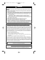
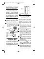
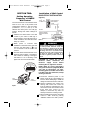
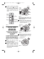
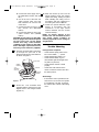
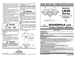
BP7415 RC188 & RC212 Receiver
10/30/09
11:29 AM
Page 1
READ AND SAVE THESE INSTRUCTIONS
Ceiling Fan/Light
Receiver & Reverse Module
Owner's Manual
For Use With SR600 Remote Control,
SR650 Remote Control and SW605 Wall Control
Receiver Model Numbers:
RC188 &
RC212
6-Speed Receiver
RC188 Receiver Supplied with Reverse Module for 188 Motor Fans
with Small Canopies
RC212 Receiver Supplied with
Reverse Module for 212 Motor Fans
RC188 Receiver & Module For Use Only with Emerson Ceiling Fan
Models: CF755, CF770, CF775, CF940, CF935, CF670, CF690 & CF695
RC212 Receiver and Module for Use Only with Emerson Ceiling Fan
Model CF787
Part No. F40BP74150000
Form No. BP7415
BP7415 RC188 & RC212 Receiver
10/30/09
!
11:29 AM
Page 2
WARNING
Safety Instructions
WARNING: To avoid fire, shock, and serious personal injury, follow all instructions
carefully.
1. Read your Owner's Manual carefully before installing the Receiver. Retain Owner's
Manual for future reference.
2. Before servicing or cleaning the ceiling fan, switch power off at service panel and lock
service panel to prevent power from being switched on accidentally. When the service
disconnecting means cannot be locked, securely fasten a warning device such as a
tag, to the service panel.
ADDITIONAL SAFETY INSTRUCTIONS FOR INSTALLATION
1.
2.
3.
4.
To avoid possible electrical shock, be sure electricity is turned off at the main fuse or
circuit breaker box before wiring.
Make certain no bare wires are exposed outside the wire connectors.
All wiring must conform to National and Local Electrical Codes.
Follow the recommended instructions for the proper method of wiring your new
Receiver. If you feel you do not have enough electrical wiring knowledge or
experience, have your Receiver installed by a licensed electrician. Any electrical work
not described in this manual should be performed by a licensed electrician.
INSTRUCTION TO THE USER (if device contains a digital device)
This equipment has been tested and found to comply with the limits for a class B digital
device, pursuant to part 15 of the FCC Rules. These limits are designed to provide reasonable
protection against harmful interference in a residential installation. This equipment generates,
uses and can radiate radio frequency energy and if not installed and used in accordance with
the instructions, may cause harmful interference to radio communications. However, there is
no guarantee that interference will not occur in a particular installation. If this equipment does
cause harmful interference to radio or television reception, which can be determined by
turning the equipment off and on, the user is encouraged to try to correct the interference by
one or more of the following measures:
•
•
•
•
Reorient or relocate the receiving antenna.
Increase the separation between the equipment and receiver.
Connect the equipment into an outlet on a circuit different from that to which the receiver
is connected.
Consult the dealer or an experienced radio/TV technician for help.
This equipment has been certified to comply with the limits for a class B computing device,
pursuant to FCC Rules. In order to maintain compliance with FCC regulations, shielded cables
must be used with this equipment. Operation with non-approved equipment or unshielded
cables is likely to result in interference to radio and TV reception. The user is cautioned that
changes and modifications made to the equipment without the approval of manufacturer could
void the user’s authority to operate this equipment.
This Class B digital apparatus meets all requirements of the Canadian
Interference-Causing Equipment Regulations.
DATE CODE:
The date code of this fan may be found on the box, stamped in ink on a white label.
You should record this data above and keep it in a safe place for future use.
2
BP7415 RC188 & RC212 Receiver
10/30/09
11:29 AM
Page 3
SECTION ONE:
General
Your Emerson Ceiling Fan may be used
with a SR600 or SR650 Remote Control, a
SW605 Wall Control, and a RC188/RC212
6-speed Receiver. The remote control or
wall control is designed to control your
ceiling fan speed, airflow direction, and
light intensity.
NOTE: The RC188 Receiver is to be
used with the following Emerson
ceiling fan models: CF940, CF935,
CF755, CF770, CF695, CF690 & CF670.
NOTE: The RC212 Receiver is to be
used with the CF787 Emerson ceiling
fan.
SR600 REMOTE
CONTROL PROCEDURES
General
Your Emerson Ceiling Fan/Light SR600
Remote Control consists of hand-held
transmitter and a receiver which is
mounted under the fan ceiling cover. The
remote control is designed to separately
control your ceiling fan speed and light
intensity.
The remote control transmitter is powered
by two AAA alkaline batteries (included).
To prevent possible damage if the
batteries should leak, be sure to remove
the batteries when the control is not to be
used for an extended period of time.
Code switches in the transmitter and
receiver may be set in 32 different
positions. If your fan and light go on and
off without using your control, you may be
getting interference from other remote
units such as garage door openers, car
alarms or security systems. To remedy this
situations, simply change the combination
code in your transmitter and receiver.
Unpackaging
The carton with the RC188 or RC212
Receiver also contains a reversing
module, seven wire connectors, four pull
chain switch plugs, and two rectangular
switch plugs.
The carton with the SR650 Remote
Control contains a storage bracket with
two mounting screws.
The carton with the SW605 Wall Control
contains three switch covers; ivory, white
and almond color.
Preset Memory Feature
Your Emerson receiver is equipped with a
preset memory feature. If the AC supply to
the receiver is powered through a wall
switch, when the switch is turned OFF, the
control will remember the light intensity
and fan speed. When the switch is turned
back ON the light and fan will resume
operation as they were prior to the switch
being turned OFF.
IMPORTANT
This Owner’s Manual is divided into three
sections. The first section, SR600/SR650
REMOTE CONTROL PROCEDURES,
describes how to install the two AAA
alkaline batteries in the SR600 remote
control transmitter and two CR2032
Lithium batteries in the SR650 remote
control transmitter, and how to set the
operating frequency of the transmitter
and receiver. The second section
describes how to install the SW605 Wall
Control. These instructions must be
performed prior to installation of the
ceiling fan as described in the third
section, CEILING FAN PROCEDURES.
Installation of Battery
1. Remove the battery cover by pressing
firmly below the arrow and sliding the
cover off the control (Figure 1).
2. Install two AAA alkaline batteries and
reinstall the battery cover.
3
BP7415 RC188 & RC212 Receiver
10/30/09
11:29 AM
1. Slide the five switch levers in the
remote control to your choice of ON
(up) or down positions. Use a ball-point
pen or small screwdriver and slide the
levers firmly up or down.
2. When power is restored, push and hold
the fan OFF button (
) for 3 to 5
seconds to set the code in the receiver.
3. If airflow is desired in the opposite
direction, press the ( ) button on the
wall control. The fan must be operating
at any speed for the reverse button to
function. The blades will turn in the
opposite direction and reverse the
airflow.
4. To set the desired fan speed, press the
( ) button to decrease the speed and
the (
) to increase the speed. The
LED display will light up to indicate the
new speed selected.
5. To set the light intensity, press and
release the LIGHT (
) button to
decrease the light intensity and the
LIGHT ( ) button to increase the light
intensity. The light will turn on at the
light intensity previously selected.
6. The sixth switch marked ON and I is for
dimming control of lights: Set switch to
ON to allow for dimming of the lights.
Set switch to I for no dimming of the
lights such as for fluorescent bulbs.
REMOTE CONTROL
LEVERS
ON
1
2
3
4 5
I
TWO AAA
BATTERIES
CODE
SWITCHES
BATTERY
COMPARTMENT
COVER
Page 4
SR600 REMOTE
CONTROL
Figure 1
Installation of Storage
Bracket for SR600
Remote Control
A storage bracket is provided for holding
your remote control when not in use. If you
desire to use the bracket, install it on a
wall that is away from excess heat or
humidity (Figure 2).
TO INSTALL BRACKET TO WALL:
SLIDE THE COVER UP TO EXPOSE THE SCREW
HOLES FOR INSTALLATION
COVER
SR650 REMOTE
CONTROL PROCEDURES
WALL
BRACKET
SCREW
HOLES (2)
General
Your Emerson Ceiling Fan/Light SR650
Remote Control consists of hand-held
transmitter with wall mount and a receiver
which is mounted under the fan ceiling
cover. The remote control is designed to
separately control your ceiling fan speed
and light intensity.
The remote control transmitter is powered
by two CR2032 Lithium batteries
(inculded). Be sure to remove the batteries
when the control is not to be used for an
extended period of time.
Code switches in the transmitter and
receiver may be set in 32 different
positions. If your fan and light go on and
off without using your control, you may be
getting interference from other remote
Figure 2
Setting Operating
Frequency of SR600
Remote Control
Your remote control has code switches
which must be set in one of 32 possible
code combinations. The five levers
(numbered 1, 2, 3, 4, and 5) on the
switches are factory-set in the ON (up)
position. Change the switch settings as
follows:
4
BP7415 RC188 & RC212 Receiver
10/30/09
units such as garage door openers, car
alarms or security systems. To remedy this
situations, simply change the combination
code in your transmitter and receiver.
11:29 AM
Page 5
WALL
BRACKET
Preset Memory Feature
Your Emerson receiver is equipped with a
preset memory feature. If the AC supply to
the receiver is powered through a wall
switch, when the switch is turned OFF, the
control will remember the light intensity
and fan speed. When the switch is turned
back ON the light and fan will resume
operation as they were prior to the switch
being turned OFF.
Installation of Battery
1. Remove the battery cover by pressing
firmly below the arrow and sliding the
cover off the control (Figure 3).
2. Install one CR2032 Lithium battery into
the battery compartment then stack the
other CR2032 Lithium battery on top of
the installed battery and reinstall the
battery cover.
REMOTE CONTROL
LEVERS
ON
CODE
SWITCHES
SR650 REMOTE
CONTROL
TWO CR2032
LITHIUM
BATTERIES
(stacked)
1
2
3
4 5
I
CR2032
CR2032
BATTERY
COMPARTMENT
COVER
Figure 3
Installation of Storage
Bracket for SR650
Remote Control
A storage bracket is provided for holding
your remote control when not in use. If you
desire to use the bracket, install remote
control storatge bracket using the two
screws provided. Install on a wall that is
away from excess heat or humidity
(Figure 4).
SCREW
HOLES (2)
Figure 4
Setting Operating
Frequency of SR650
Remote Control
Your remote control has code switches
which must be set in one of 32 possible
code combinations. The five levers
(numbered 1, 2, 3, 4, and 5) on the
switches are factory-set in the ON (up)
position. Change the switch settings as
follows:
1. Slide the five switch levers in the
remote control to your choice of ON
(up) or down positions. Use a ball-point
pen or small screwdriver and slide the
levers firmly up or down.
2. When power is restored, push and hold
the fan OFF button (
) for 3 to 5
seconds to set the code in the receiver.
3. If airflow is desired in the opposite
direction, press the ( ) button on the
wall control. The fan must be operating
at any speed for the reverse button to
function. The blades will turn in the
opposite direction and reverse the
airflow.
4. To set the desired fan speed, press the
( ) button to decrease the speed and
the (
) to increase the speed. The
LED display will light up to indicate the
new speed selected.
5. To set the light intensity, press and
release the LIGHT (
) button to
decrease the light intensity and the
LIGHT ( ) button to increase the light
intensity. The light will turn on at the
light intensity previously selected.
6. The sixth switch marked ON and I is for
dimming control of lights: Set switch to
ON to allow for dimming of the lights.
Set switch to I for no dimming of the
lights such as for fluorescent bulbs.
5
BP7415 RC188 & RC212 Receiver
10/30/09
11:29 AM
SECTION TWO:
Page 6
Installation of Wall Control
SINGLE-POLE INSTALLATION
Setting Operating
Frequency of SW605
Wall Control
(Figure 6)
HOT
SW605 FAN/LIGHT
WALL CONTROL
BLK
HI
LIGHT
Your wall control has code switches which
must be set in one of 32 possible code
combinations (Figure 5). The five levers
(numbered 1, 2, 3, 4, and 5) on the
switches are factory-set in the ON (up)
position. Change the switch settings as
follows:
MED
LOW
FAN OFF
EMERSON®
OFF
Figure 6
!
CAUTION: To reduce the risk of
electrical shock, disconnect the
electrical supply circuit before
installing the fan, light kit or receiver.
WALL CONTROL
CODE SWITCHES
NOTE: Make all wiring connections
using wire connectors (supplied). Make
sure that all connections are tight,
including ground, and that no bare wire
is visible at the wire connectors, except
for the ground wire.
ON
WALL
CONTROL
4 5
WARNING
Turning off wall switch is not sufficient.
To avoid possible electrical shock, be
sure electricity is turned off at the main
fuse or circuit breaker box before wiring.
All wiring must be in accordance with
National and Local codes and the ceiling
fan must be properly grounded as a
precaution against possible electrical
shock.
3. The sixth switch marked ON and I is for
dimming control of lights: Set switch to
ON to allow for dimming of the lights.
Set switch to I for no dimming of the
lights such as for fluorescent bulbs.
3
GROUND
RECEIVER LOCATED
WITHIN THE CEILING
COVER
2. When power is restored after
installation of the wall control, push and
hold the fan OFF button (
) for
3 to 5 seconds to set the code in the
receiver.
2
LOAD
BLACK
NEUTRAL
1. Slide the five switch levers in the wall
control to your choice of ON (up) or
down positions. Use a ball-point pen or
small screwdriver and slide the levers
firmly up or down.
1
BLACK
ON
I
1. Disconnect electrical power to the
branch circuit at the circuit breaker or
fuse box before attempting to install the
ceiling fan wall control into the outlet box.
2. Remove faceplate and screws from
existing wall control. Pull control out
from the wall box. Determine the “hot”
wire and the “load” wire and disconnect
these wires from control. Do not
attempt to disconnect any wires not
already connected to existing control.
3. Before installing wall control, place wall
control in “OFF” mode by pushing
“ON/OFF” switch to the “OFF” position.
CODE
SWITCHES
Figure 5
6
BP7415 RC188 & RC212 Receiver
!
10/30/09
11:29 AM
3-WAY INSTALLATION
WARNING
(On fan controlled by two different wall
controls) (See Figures 8 and 9.)
Do not connect any neutral (white) wire to
this control. Incorrect wiring will damage
this control.
!
1. Disconnect electrical power to the
branch circuit at the circuit breaker or
fuse box before attempting to install the
ceiling fan wall control into the outlet box.
WARNING
!
Check to see that all connections are tight
and that no bare wires are visible at the
wire connectors.
2. At all wall box locations remove
faceplates and screws from existing
controls. Pull controls out from wall
boxes and determine which wall box
contains the “hot” lead and which wall
box contains the “load” wire. Also,
identify traveler wires which are
common to both wall boxes.
Disconnect wires from existing controls
only. Do not attempt to disconnect any
wires not already connected to existing
controls.
3. Before installing wall control, place wall
control in “OFF” mode by pushing
“ON/OFF” switch to the “OFF” position.
4. Install a wall control in the wall box
containing the “hot” wire first. Connect
the black wire of the wall control to the
“hot” wire. Securely connect wires with
wire connectors supplied.
5. Connect one black wire of the wall
control to both remaining traveler wires
in the wall box and secure with wire
connector supplied.
NOTE: Retrofit 3-way installations are
likely to include two traveler wires
between the two wall boxes. In new
construction, only one traveler wire Is
required (See Figure 9).
8. Install decorator wall plate (purchased
separately) using the two screws
provided with wall plate. Leave wall
control in “OFF” mode until fan
installation is completed (Figure 7).
SCREWS (2)
HOT
TO
E
120V
AC SOURC
TO
LOAD
K
GR
AC
BL
OU
WARNING
Do not connect any neutral (white) wire to
this control. Incorrect wiring will damage
this control.
7. The wall control is supplied with a
white, ivory, and almond color switch
covers. Choose the finish that best
suits your needs and snap the cover
onto the wall control (Figure 7).
K
BL
WARNING
Turning off wall switch is not sufficient.
To avoid possible electrical shock, be
sure electricity is turned off at the main
fuse or circuit breaker box before wiring.
All wiring must be in accordance with
National and Local codes and the ceiling
fan must be properly grounded as a
precaution against possible electrical
shock.
4. Connect one black wire of wall control
to the “hot” wire. Securely connect
wires with wire connectors supplied
(Figure 7).
5. Connect one black wire of wall switch
to the “load” (black) wire in wall box.
Securely connect wires with wire
connector supplied.
6. Screw wall control into wall box using
the supplied screws.
Leave wall
control in “OFF” mode until fan
installation is completed.
!
Page 7
ND
WALL
SWITCH
BOX
COVER
FAN/LIGHT
DECORATIVE
WALL CONTROL
WALL PLATE
Figure 7
7
BP7415 RC188 & RC212 Receiver
10/30/09
11:29 AM
3-WAY WIRlNG DIAGRAM:
NEW CONSTRUCTION
STANDARD WIRING FOR EXISTING
3-WAY CONTROLS
WARNING
!
HOT
LIGHT
®
EMERSON
OFF
ON
TRAVELER WIRES
SW605
FAN/LIGHT
WALL
CONTROL
LIGHT
NEUTRAL
RECEIVER LOCATED
WITHIN THE CEILING
COVER
ON
BLK
LOAD
BLACK
HOT
BLK
BLK
BLK
HI
HI
LIGHT
LIGHT
MED
MED
LOW
LOW
FAN OFF
FAN OFF
GROUND
EMERSON ®
EMERSON®
OFF
FAN/LIGHT
WALL CONTROL
OFF
ON
TRAVELER WIRES
ON
BLACK
TRAVELER
WIRE
3-WAY WIRING DIAGRAM: RETROFIT
EMERSON ®
OFF
BLK
BLACK
LOAD
HI
MED
LOW
FAN OFF
BLK
HI
MED
LOW
FAN OFF
EXISTING
WALL CONTROL
BLK
BLACK
Check to see that all connections are tight
and that no bare wires are visible at the
wire connectors.
HOT
Page 8
LOAD
Figure 9
Figure 8
6. Screw wall control into wall box using
the supplied screws.
Leave wall
control in “OFF” mode until fan
installation is completed.
Operation of Your Wall
Control (Figure 10)
7. The wall control is supplied with a
white, ivory, and almond color switch
covers. Choose the finish that best
suits your needs and snap the cover
onto the wall control (Figure 7).
IMPORTANT
Fan installation must be completed,
including the installation of the fan
blades, before testing the remote control.
8. Next, install the other wall control into
the wall box containing the load wire.
Connect the black wire of the wall
control to the traveler wire(s) already
connected to the black wire (in the
other wall box). Secure with wire
connectors supplied.
Your wall control has full control of your
fan and light.
NOTE: Prior to operation of the fan and
light from the wall control, set the fan
speed to HIGH (....) and turn the light
ON (
).
9. Connect one black wire of the wall
control to the “load” (black) wire and
secure with wire connector supplied.
1. To set the desired fan speed, press the
( ) button to decrease the speed and
the ( ) to increase the speed. The LED
display will light up to indicate the new
speed selected.
2. To turn the light on and off, press and
release the LIGHT (
) button. To set
the light intensity, press and hold the
LIGHT ( ) button. The light will turn on
at the light intensity previously selected.
3. Your wall control comes complete with
your choice of three wall cover plates;
ivory, white and light almond.
8
BP7415 RC188 & RC212 Receiver
10/30/09
11:29 AM
4. If airflow is desired in the opposite
direction, press the ( ) button on the
wall control. The fan must be operating
at any speed for the reverse button to
function. The blades will turn in the
opposite direction and reverse the
airflow.
CAPACITOR
SPEED
CONTROL
SWITCH
FAN
BUTTON
MOTOR
CONNECTOR
KNURLED
NUT
WIRING
HARNESS
CONNECTOR
PULL
CHAIN PLUG
SWITCH HOUSING
POWER
INDICATOR
LIGHT
FAN
DIRECTION
Page 9
LIGHT
BUTTON
REVERSING
SWITCH
SCREW (2)
Figure 11
NOTE: Keep the uplight switch if you
think you may like to return to manual
control in the future.
HIGH TO LOW
SPEED BUTTONS
3. Remove two screws securing the
reversing switch to the switch housing
and place the pull chain plug in the
exposed hole.(Figure 12).
ON/OFF SWITCH
O = OFF / — = ON
SPEED CONTROL
SWITCH
Figure 10
KNURLED
NUT
SECTION THREE:
CEILING FAN
PROCEDURES
PULL
CHAIN PLUG
Installation to Operate the
Ceiling Fan, Downlight
and Uplight
SWITCH HOUSING
REVERSING
SWITCH
SCREW (2)
Figure 12
4. Remove the speed control switch and
reversing switch capacitor. Position the
RC188/RC212 module into the switch
housing (Figure 13).
IMPORTANT
It is important that you also follow the
installation instructions contained in
the Owner’s Manual supplied with your
Ceiling Fan. Pay particular attention to
the Safety Instructions and WARNING
notes.
1. Remove and retain the screws
securing the housing cover to the
switch housing (Figure 11).
2. All Ceiling Fan Models. Disconnect
the motor connector from the wiring
harness connector (Figure 11).
Remove the knurled nut securing the
speed control switch to the switch
housing and place the pull chain plug in
the exposed hole.
RC188/RC212 MODULE
SWITCH HOUSING
PULL
CHAIN
PLUG
Figure 13
9
BP7415 RC188 & RC212 Receiver
10/30/09
11:29 AM
5. Connect the 6-pin wiring connector of
the module to the ceiling fan motor
assembly wiring connector. The
connectors are keyed and must be
mated correctly before they can be
engaged (Figure 14).
Page 10
TO 110V
RECEIVER
SUPPLY
BLACK
SUPPLY
WIRE
LISTED GENERAL
USE ON/OFF WALL
SWITCH OR
OPTIONAL
EMERSON SW605
WALL CONTROL
WHITE SUPPLY
WIRE
BLUE RECEIVER WIRE*
WHITE RECEIVER
WIRE
BLACK RECEIVER WIRE
BLACK/WHITE
RECEIVER WIRE
YELLOW RECEIVER
WIRE**
BLUE FAN WIRE
WHITE FAN WIRE
BLACK FAN WIRE
6-PIN WIRING
CONNECTOR
FROM CEILINGFAN
YELLOW FAN WIRE
(FROM UPLIGHT)
6-PIN WIRING
MODULE CONNECTOR
FROM SWITCH
HOUSING
YELLOW UPLIGHT WIRES
(NOT PRESENT ON ALL FANS)
DOWNROD
RED AND BROWN
WIRES - CAPPED.
DO NOT REMOVE
WIRE
CONNECTORS
PULL CHAIN
PLUG
MOTOR COUPLING
FAN HOUSING
OPTIONAL
LIGHT FIXTURE
Figure 14
* IF YOUR CEILING FAN DOES NOT
HAVE A DOWNLIGHT, CAP THE BLUE
RECEIVER WIRE USING A WIRE
CONNECTOR.
6. Assemble your ceiling fan (including
the fan blades), install the hanger
bracket, and then hang the fan in
accordance with the instructions in the
Ceiling Fan Owner’s Manual. Wire the
ceiling fan and receiver and complete
the installation in accordance with the
following Steps 6 through 12.
** IF YOUR CEILING FAN DOES NOT
HAVE AN UPLIGHT, THERE WILL BE
NO YELLOW FAN WIRE.
IN THIS CASE, CAP THE YELLOW
RECEIVER WIRE USING A WIRE
CONNECTOR.
Figure 16
9. Using wire connectors (supplied),
make wiring connections as follows
(Figure 15 and 16):
a. Connect the green ground wires
from the hanger bracket and the
hanger ball to the supply ground
wire (bare or green).
b. Connect the white fan wire and the
white supply wire to the white
receiver wire (AC IN/MOTOR N).
c. Connect the black fan wire to the
black receiver wire (TO MOTOR
L).
7. Pull the wire leads, coming from the
end of the downrod, and the supply
wires through the open side of the
hanger bracket. (Figure 15).
8. Position the RC188/RC212 Receiver in
the ceiling cover so that the flat side of
the receiver faces up and the open
portion of the receiver is to the right, as
shown in Figure 15.
OUTLET BOX
BLACK SUPPLY WIRE
BLACK FAN WIRE
HANGER BRACKET
HANGER BRACKET
GROUND WIRE
(GREEN)
BLACK/WHITE RECEIVER WIRE
BLUE FAN WIRE
HANGER BALL
GROUND WIRE
(GREEN)
BLUE RECEIVER
WIRE
OPEN PORTION
OF RECEIVER
HERE
SUPPLY
GROUND
WIRE (GREEN
OR BARE)
RECEIVER
YELLOW FAN WIRE
YELLOW RECEIVER
WIRE
BLACK RECEIVER
WIRE
WHITE RECEIVER WIRE
WHITE SUPPLY
WIRE
CEILING COVER
Figure 15
WHITE FAN WIRE
WIRE CONNECTOR
10
BP7415 RC188 & RC212 Receiver
10/30/09
11:29 AM
d. Connect the black supply wire to
the black/white receiver wire (AC
IN L).
e. Cut off the end of the blue and
yellow receiver wires and strip
back insulation 1/2” from the end
of the wires.
f. Connect the blue fan wire to the
blue receiver wire (BOTTOM
LIGHT).
g. Connect the yellow fan wire to the
yellow receiver wire (UPPER
LIGHT).
CAUTION: If your ceiling fan does NOT
have an uplight, there will be NO yellow
fan wire. In this case, cap the yellow
receiver wire using a wire connector
(supplied). If your ceiling fan does NOT
have a downlight, cap the blue receiver
wire using a wire connector (supplied).
12. Slide the receiver up and over the
hanger bracket. Press the receiver
against the ceiling, holding it in place
while installing the ceiling cover in
accordance with the instructions in
the Ceiling Fan Owner’s Manual.
13. Install the optional Emerson Light
Fixture in accordance with the
instructions in the Light Fixture
Owner’s Manual. Use the screws
removed in Step 1.
NOTE: To prevent damage to the
receiver, turn “off” the electricity at the
wall switch before installing or
removing light bulbs on the ceiling fan
or light fixture.
Trouble Shooting
Fan/Light Fails to Operate
10. nsert the connected ends of the wires
up through the open side of the
hanger bracket and into the outlet box
as shown in Figure 17.
• Check that the speed switch on the
fan is set to HIGH (....) speed.
• Check that the light switch is on.
• Check that the battery is good
(red indicator light should light when
any button is pressed).
• Check that the receiver is wired
properly.
• Check that code switches in the
remote control and receiver are set in
the same position.
OUTLET BOX
HANGER
BRACKET
1-1/4"
THREADED
STUDS (2)
Page 11
RECEIVER
CEILING
COVER
Short Range
• If the remote control operates the fan
when close to it, but does not operate
it at a distance of 40 feet, try placing
the antenna wire outside of the ceiling
cover.
Figure 17
11. Screw two 1-1/4” threaded studs
(supplied with the ceiling fan) into the
tapped holes in the hanger bracket
(Figure 15).
11
BP7415 RC188 & RC212 Receiver
10/30/09
11:29 AM
Page 12
LIMITED WARRANTY
What The Warranty Covers:
All products covered by this Owner’s Manual are warranted against all defects in workmanship and materials.
You must be the original purchaser or user of the product to be covered.
What The Period Of Coverage Is:
All components are covered by this warranty for one year from the date you purchased your Receiver ANY
IMPLIED WARRANTY OF MERCHANTABILITY OR FITNESS FOR A PARTICULAR PURPOSE, MADE WITH
RESPECT TO COMPONENTS AND ACCESSORIES IS ALSO LIMITED TO ONE YEAR.
What Will Emerson Electric Co. Do To Correct Problems:
Emerson will replace a defective Emerson Receiver at no charge to you. We will ship the repaired product or
replacement to you at no charge, but you are responsible for all costs or removal, reinstallation and
shipping of the product to Emerson.
How Can You Get Service:
YOU MUST HAVE PROOF OF YOUR PURCHASE OF THE RECEIVER TO OBTAIN LIMITED WARRANTY SERVICE.
KEEP YOUR RECEIPT OR OTHER PROOF OF PURCHASE. You can return the product to our factory or to your
nearest authorized service center.
• To return the product to the factory, obtain a return authorization and service identification tag by writing to
Air Comfort Products, Division of Emerson Electric Co., 8100 W. Florissant Ave., St. Louis, MO 63136.
Include all model numbers shown on the product with your request.
• To return the product to an authorized service center, call 1-800-654-3545 for the address of the nearest
authorized service center.
You will be responsible for all insurance, freight or other transportation charges to our factory or authorized
service center. Your Emerson Receiver should be properly packed to avoid damage in transit since we will not
be responsible for any such damage.
What Is Not Covered:
This warranty also does not cover any defects, malfunctions or failures caused by:
• Repairs by persons not authorized by Emerson Electric Co.,
• Use of parts or accessories not authorized by Emerson Electric Co.,
• Mishandling, improper installation, modifications or damage to your receiver while in your possession, or
• Unreasonable use, misuse, abuse, including failing to do reasonable and necessary maintenance, and normal
wear and tear.
Additionally, this warranty and any implied warranty of merchantability or fitness for a particular purpose are
voided when:
• The original purchaser or user ceases to own the product, or
• The ceiling fan is moved from its original point of installation.
This warranty is only valid within the 50 states of the United States and the District of Columbia. No other
written or oral warranties apply, and no employee, agent, dealer or other person is authorized to give any
warranties on behalf of Emerson Electric Co.
REPAIR, REPLACEMENT OR A REFUND ARE THE EXCLUSIVE REMEDIES AVAILABLE UNDER THIS
WARRANTY AND EMERSON IS NOT RESPONSIBLE FOR DAMAGES OF ANY KIND, INCLUDING INCIDENTAL
AND CONSEQUENTIAL DAMAGES. Incidental damages include but are not limited to such damages as loss of
time and loss of use. Consequential damages include but are not limited to the cost of repairing or replacing
other property which was damaged if this product does not work properly.
How State Law Relates To The Warranty:
Some states do not allow the exclusion or limitation of incidental or consequential damages so the above
exclusion or limitation may not apply to you. This warranty gives you specific legal rights, and you may also
have other rights which vary from state to state.
Air Comfort Products
DIVISION OF EMERSON ELECTRIC CO.
8100 W. Florissant • St. Louis, MO 63136
Part No. F40BP74150000
Printed in China 10/09
Form No. BP7415