1
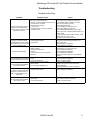
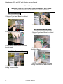
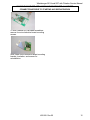
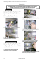
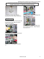
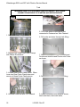
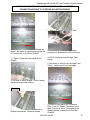
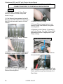
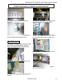
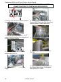
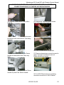
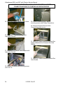
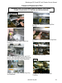
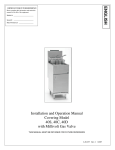
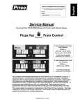
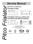
IMPORTANT FOR FUTURE REFERENCE
Please complete this information and retain
this manual for the life of the equipment:
Model #: _____________________
Serial #: _____________________
Date Purchased: _______________
SERVICE MANUAL
For SOLSTICE ELECTRIC MODELS
SE14 and SE7
With Filtration
Whataburger
L22-289 Rev 00
Whataburger SE14 and SE7 with Filtration Service Manual
2
L22-289 Rev 00
Whataburger SE14 and SE7 with Filtration Service Manual
TABLE OF CONTENTS
Theory of Operation ...............................................................................................................4
Troubleshooting .....................................................................................................................5
Troubleshooting Fryer .........................................................................................................5
Troubleshooting Filter..........................................................................................................6
Component Troubleshooting ..................................................................................................7
Probe:..................................................................................................................................7
Heat Demand Contactor:.....................................................................................................7
Hi-Limits: .............................................................................................................................7
Drain Valve & Filter Return Valve Switches: .......................................................................8
Transformer:........................................................................................................................8
Elements: ............................................................................................................................8
Safety (Side On) Contactor: ................................................................................................8
Relay Board: .......................................................................................................................8
Computer Control: ...............................................................................................................8
Back-Up Solid State Control:...............................................................................................9
Component Replacement Fryer ...........................................................................................12
Cover Removal..................................................................................................................12
Front Panel Bezel...........................................................................................................12
Entrance Box Covers Lower...........................................................................................12
Entrance Box Covers Lower...........................................................................................12
Entrance Box Wire Guard ..............................................................................................13
Control Components .........................................................................................................14
Main On/Off Switch ........................................................................................................14
Solid State Thermostat/Back-up.....................................................................................14
Wire Reduction Board (WRB) ........................................................................................14
Entrance Box.....................................................................................................................16
Transformer....................................................................................................................16
Heat Demand Contactor.................................................................................................16
Safety Contactor.............................................................................................................17
Tank ..................................................................................................................................18
Probe..............................................................................................................................18
Hi-Limit ...........................................................................................................................19
Element ..........................................................................................................................20
Drain Valve Interlock Switch...........................................................................................20
Tank Replacement .........................................................................................................21
Component Replacement Filter............................................................................................25
Pump Removal...............................................................................................................25
Pump..............................................................................................................................25
Pump Box.......................................................................................................................26
Pump Circuit Breaker .....................................................................................................27
Pump Relay....................................................................................................................27
Pump Transformer .........................................................................................................27
Pump Actuator (Switch)..................................................................................................28
Pump Actuator (Actuator)...............................................................................................28
Flush Hose Assembly.....................................................................................................29
Schematics...........................................................................................................................30
Solid State Thermostat Calibration.......................................................................................35
Computer Programming Instructions....................................................................................36
L22-289 Rev 00
3
Whataburger SE14 and SE7 with Filtration Service Manual
Theory of Operation
The SE14 and SE7 fryer components
function in specific order of operation.
Knowing and understanding the sequence of
fryer and components operation will enable
you to diagnose equipment failure more
accurately.
Filter System:
•
Pulling the RED filter return valve handle
will close the proximity switch causing
the “pump run” relay to be energized.
The pump motor will begin to run.
Closing the filter return valve handle will
de-energize the relay and the pump
motor will stop running.
•
The pump system is equipped with a
circuit breaker which will de-energize the
system and the heat tape in the event of
over current. The circuit breaker switch
must be in the ON position for the pump
and heat tape to operate.
•
The return piping system may be
provided with optional heat tape to
prevent solidification of solid shortening.
the heat tape is low wattage and is on
constantly to maintain liquid shortening in
the line.
Heating System
Power to the machine is turned ON:
• If Fuse F1 on the Relay board is good,
the A.C. light will illuminate. The
computer is supplied with 24VAC and, if
the drain valve handle is closed, the
proximity switch will supply 24 VAC to
the DVI (drain valve interlock) Input at
the computer.
•
The controller is turned ON:
•
The side on relay will be energized,
closing the circuit and the S.O. light on
the Relay Board will illuminate. If the HiLimit is NOT tripped the safety (side on)
contactor will energize.
•
Controller calls for heat:
•
The 24VDC “heat demand” relay will
energize supplying the heat demand
contactor with 24 VAC and the H.D. light
on the Relay Board will illuminate. This
will also supply the controller with a heat
feedback signal.
Hi-Limit System:
•
4
If the hi-limit trips, it causes the side on
and heat demand contactors to lose 24
VAC supply and the heat feedback loses
24 VAC. The computer will display
HEATING. The Heat Demand lamp will
be lit on the Back-up T-stat, the heat
feedback lamp will not be lit. After the hilimit resets (unit cools to 375 F ±20 F)
the controller will have to be turned off
and back on for the unit to heat.
L22-289 Rev 00
Whataburger SE14 and SE7 with Filtration Service Manual
Troubleshooting
Troubleshooting Fryer
PROBLEM
POSSIBLE CAUSE
A. Main Power Switch not turned on
B. Back-up T-stat not turned ON.
C. Back-up T-stat not turned to Primary Control.
D. Hood cords not connected.
E. No power to the machine.
Computer display does not light or
F. Fuse F1 blown.
Back-up T-stat is switched to
G. Transformer T1A or T1B not functioning.
Seconday control, but Green power
H. Controller Failed
light does not turn on.
Computer Shows "HEATING" ,or A. Hi-Limit tripped.
Back-up T-stat Yellow Head
B. Heat Demand Contactor.
Demand lamp is lit, but the Yellow C. Relay Board.
Heat Feedback Lamp is not lit, and
machine does NOT heat.
A. Unit is in Melt Cycle
B. Safety Contactor
C. Heat Demand Contactor
Machine is heating slowly
D. Element
E. Loss of power on one leg of 3 phase
input power
A. Temperature calibration
Oil is hotter or colder than computer
B. Probe
displays or Back-up Tstat is set to.
C. Probe wiring terminals
A. Blue Drain Valve not fully closed.
Computer diplays "DRAIN" or BackB. Sensor Switch
up T-stat Yellow Heat Feedback
C. Incorrect Switch gap/alignment.
lamp Flashes 7 times.
A. Safety contactor
Computer heat demand lights are
B. Heat Demand Contactor
lit, or Back-up T-stat heat demand
lights are lit; machine does not
heat. HD & SO lights on relay
board are lit.
A. Shorted probe
Computer displays "Probe" or BackB. Open probe
up T-stat Yellow Heat Feedback
C. Probe wiring terminals
lamp flashes 3 times.
L22-289 Rev 00
ACTION
A. Turn on Main Power Switch
B. Turn Power switch to Back-up T-stat to On.
C. Turn Selector Switch on Back-up T-stat to
Primay Control position (one dot).
D. Connect all Hood cords
E. Check building circuit breaker, verify
power cord is plugged in all the way.
F. Check Wire Reduction Board, if 24VAC light
is not lit, check fuse. Replace if defective with 2.5A
fast acting fuse.
G. If fuse is good and 24VAC light is still off, check
votage in and out of T1A or T1B.
H. Transfer control to Back-up T-stat.
A. Once the oil temp has gone below 375°F ± 20°F,
the Hi-Limit should reset automantically, if not,
replace the Hi-Limit.
B. Check & Replace if defective.
C. Check & Replace if defective.
A. Wait for the computer to finish melt cycle, or
switch Back-Up T-stat out of melt cycle.
B. Check & Replace if defective.
C. Check & Replace if defective.
D. Check & Replace if defective.
E. Check input power. Repair or call a qualified
electrican.
A. Adjust temperature offset up to ± 10°F.
B. Check & Replace if defective
C. Clean or repair terminals.
A. Check position of handle.
B. Switch may be loose or have loose wires,
replace if defective.
C. Check gap/alignment, replace if defective.
A. Check & Replace if defective.
B. Check & Replace if defective.
A. Check probe & replace if defective.
B. Check probe & replace if defective.
C. Clean or repair terminals.
5
Whataburger SE14 and SE7 with Filtration Service Manual
Troubleshooting Filter
PROBLEM
POSSIBLE CAUSE
A. Red Filter Return Handle not completely
open.
B. Filter Circuit Breaker may be tripped or
in the off position.
Red Filter Return Handle is pulled C. Filter Pump Motor Thermal Overlaod may
out, but no pump sound can be be Tripped.
heard
D. Sensor switch may be loose or defective.
E. Power cord unplugged or loose.
Drain Valve is closed, computer A. Blue Drain Valve not fully closed.
has been reset, but computer still B. Sensor Switch
displays "Draining", or Back-up T- C. Incorrect switch gap/alignment.
stat has been reset, but Yellow
Heat Feedback lamp flashes 7
times.
A. Dirty Filter Wire Mesh Envelope.
Oil is returning to the tank slowly B. Strainer cap dirty.
or not at all.
C. Filter Pan not pushed in completely.
D. O-rings not sealing on pick-up tube.
A. Strainer cap not tight.
Air bubbles are in the oil be
B. Strainer cap not in pick-up tube
returned to the tank.
C. Filter Pan not pushed in completely.
D. O-rings not sealing on pick-up tube.
A. Drain valve is not fully open.
B. Drain line is plugged with debris.
Drain Valve is open, the oil is
draining slowly or not at all.
6
L22-289 Rev 00
ACTION
A. Pull on red Filter Return Handle to make sure
valve is completely open.
B. Reset the Circuit Breaker or press it to the
ON position.
C. Push the Red Reset Button on the end of the
Pump Motor.
D. Check that the switch is tight and that it has the
correct gap. Replace if defective.
E. Check the power cord at the fryer Entrance Box
and at the Pump Box and make sure that the power
cords are plugged in and/or pushed in all the way.
A. Check position of handle.
B. Switch may be loose or have loose wires,
replace if defective.
C. Check gap/alignment, replace if defecitive.
A. Clean Filter Wire Mesh Envelope.
B. Remove strainer cap and clean.
C. Push Filter Pan in.
D. Check & replace if defective.
A. Tighten strainer cap.
B. Install strainer cap.
C. Push Filter Pan in.
D. Check & replace if defective.
A. Apply a little more pressure to the Blue Drain
Valve handle to check that the Drain Valve is
fully open.
B. Use the clean out rod to clear the Drain Valve
opening. If this does not clear the blockage, close
the drain valve, and call for service.
Whataburger SE14 and SE7 with Filtration Service Manual
Component Troubleshooting
Probe:
Heat Demand Contactor:
The resistance of the probe will change as
the temperature changes. The resistance
will decrease as the temperature rises. The
lower the temperature the greater the
resistance change will be per degree of
temperature change, as the temperature
approaches the working range of the probe,
the resistance change will become more
linear.
The heat demand contactor has a 24 VAC
coil and will energize when the correct
voltage is supplied to the coil. when
energized, the contacts will close, allowing
current to flow through the elements. The
coil resistance is 192 Ohms out of current.
TEMP RESISTANCE TEMP RESISTANCE
OHM Ω
OHM Ω
°F/°C
°F/°C
60/16
139,055
330/166
1,192
80/27
84,644
335/168
1,123
100/38
53,146
340/171
1,058
120/49
34,328
345/174
998
140/60
22,755
350/177
942
160/71
15,446
355/179
890
180/82
10,716
360/182
841
200/93
7,586
365/185
795
210/99
6,427
370/188
752
220/104
5,470
375/191
712
240/116
4,013
380/193
675
260/127
2,991
385/196
640
280/138
2,262
390/199
607
300/149
1,734
395/202
576
320/160
1,347
400/204
547
325/163
1,267
If the probe is suspect, check its resistance
and the oil/air temperature at which it was
taken. Compare these values on the chart
below.
If the probe returns an open circuit or 0
Ohms reading it should be replaced. If the
resistance varies more than 30 Ohms when
being checked between 325-375 F the
probe will give a false temperature reading
on the controller and should be calibrated
(up to 10 F) or replaced. However, it will
continue to operate at a slightly higher or
lower temperature.
Allow the oil to cool and check the probe
resistance at a lower temperature. As can
be seen from the chart a greater variation
can be tolerated at a lower temperature.
Hi-Limits:
The hi-limit switch is a normally closed
switch until the temperature at the hi-limit
bulb reaches 425 F ± 20 F.
WARNING!
This test should be performed by a
qualified technician only! Monitor the
fryer closely. This test will cause the oil
to heat past the normal operating
temperature and can cause damage to
the machine and its operator if care is
not taken.
WARNING!
This test will cause the elements to heat
continuously. Remove test resistor
when test is complete. Leaving the test
resistor in the fryer could cause damage
to the equipment and/or personal injury.
To test the hi-limit, use a 2kΩ - 5 kΩ resistor
to simulate a 230 F - 275 F temperature.
This will cause the elements to heat
continuously until the hi-limit trips or the fryer
is turned off.
•
If testing with the computer, plug the
resistor in at connector J41 behind the
front panel.
•
If testing with the back-up thermostat
behind the door, plug the resistor in at
connector J43 behind the front panel.
If the switch does note trip between the
prescribed limits it is defective and should be
L22-289 Rev 00
7
Whataburger SE14 and SE7 with Filtration Service Manual
replaced. Once tripped, the switch cannot
be reset until the oil has cooled to
approximately 375 F ± 20 F. If the switch
does not reset after oil has cooled it is
defective.
Drain Valve & Filter Return Valve
Switches:
These switches are magnetically operated
proximity switches. When the BLUE Drain
Valve handle is moved to the open position
(down), the Actuator will move away from
the switch causing the switch to open.
When the Drain Valve is closed the switch
will close.
Pulling the RED Filter Return Valve Handle
will close the proximity switch causing the
“pump on” relay to be energized. The pump
will begin to pump. Pushing the filter return
valve handle will de-energize the relay and
the pump will stop pumping. These switches
can also be checked with an Ohm meter.
The normal gap between the Actuator and
the Sensor switch on the valve handle is
1/8” –1/4” (3-6mm)
208 Volt Element
240 Volt Element
Safety (Side On) Contactor:
Check the coil with and Ohm meter, the
resistance should be approximately 3 – 6
Ohms out of circuit. If it does not have this
resistance it should be changed.
Relay Board:
Note: J connectors are marked on the relay
board.
•
With 24 VAC supplied to pin #2 at
connector J35 and a good F1 fuse, the
relay board will have a 24 VAC output at
pin #2 on connectors J33 and J34 and
the A.C. indicator will be illuminated.
•
When the board receives a 24 VDC side
on input at pin #7 on connectors J31 or
J33 the S.O. indicator will illuminate, the
side on relay (S.O.) will energize and
there will be a 24 VAC output at pin #4
on connector J32.
•
When the board receives a 24 VDC heat
demand input at pin #6 on connectors
J31 or J33, the H.D. indicator will
illuminate, the heat demand relay (H.D.)
will energize and there will be continuity
between pin #1 and pin #2 at connector
J32.
Transformer:
Transformers are multiple input voltage 24
volt output voltage and can be checked by
reading the input and output voltages. A
quick check for 24 VAC can be done at the
relay board behind the computer. The AC
led will be lit if the F1 fuse is good and the
board is receiving 24 VAC.
Computer Control:
Elements:
Each Element has three coils, check all
element coils out of circuit with an Ohm
meter, the resistance should correspond to
the chart below, if the resistance is outside
of the rating, the element will need to be
changed. Also check for continuity to
ground on each end of the suspect element,
there should be no continuity to ground.
8
14.1-16.4 Ohms
18.8-21.8 Ohms
Note: All controller test points are at
connector P/J1 (closest connector to the
controller).
•
With 24 VAC supplied to pin #1 (24 VAC
supply) and pin #5 (24 VAC input from
DVI), the display should read “READY”.
L22-289 Rev 00
Whataburger SE14 and SE7 with Filtration Service Manual
•
With the controller turned on, there will
be a 24 VDC output at pin #9 (side on).
•
When the controller calls for heat, there
will be a 24 VDC output at pin #8 (heat
demand) and a 24 VAC input at pin #6
(heat feed back). If the heat demand
contactor does not pull in, this would
indicate a break in the heat demand
circuit.
1. Check the hi-limit switch (is it open or
tripped.
With the controller turned on, there will
be a 24 VDC output at pin #9 (side on)
and the green indicator will be
illuminated.
•
When the controller calls for heat, there
will be a 24 VDC output at pin #8 (heat
demand), the yellow indicator on the left
will be illuminated and there will be a 24
VAC input at pin #6 (heat feed back).
•
When the controller receives the 24 VAC
input at pin #6 the yellow indicator on the
right will illuminate. If the controller does
not receive the 24 VAC input at pin #6,
the indicator will not illuminate. This
would indicate a break in the heat
demand or heat fee back circuit.
2. Check the heat demand relay (H.D.) on
the relay board (is heat demand relay
energized, continuity through COM and
NO contacts).
•
•
•
If display reads “PROBE OP”,“OPEN”,
Ohm test the temperature probe. Check
the wires and connectors between the
probe and controller for continuity.
If display reads “SYSTEM” “FAILURE”,
test the temperature probe and the wires
and connectors between the probe and
controller for a short.
If display reads “DRAINING” “TURN
OFF”, verify that the drain valve is
closed, check the proximity switch on the
drain valve, turn the fryer off, then turn
the fryer on.
Back-Up Solid State Control:
The 24 VAC supply passes through the solid
state back-up transfer switch to the
computer. If the transfer switch is set to
back-up or if the back-up controller has been
unplugged, the primary controller will not
work. A jumper must be installed on the
relay board (connection J33, pin #2 to pin
#10) to allow the primary controller to
function if the back-up controller is removed.
•
1. Check the hi-limit switch (is it open or
tripped.
2. Check the heat demand relay (H.D.) on
the relay board (is heat demand relay
energized, continuity through COM and
NO contacts).
•
If the green indicator and the yellow
indicator on the left come on and shut off
when the controller is turned on, that
indicates an open or shorted probe or
wires in between the probe and the
controller.
•
If none of the indicators illuminate when
the controller is turned on, verify that the
drain valve is closed and that the
magnetic proximity switch has continuity
when the drain valve is closed. Also
verify that there is 24 VAC at pin #1 (24
VAC supply) and pin #5 (24 VAC input
from DVI).
24 VAC is supplied to the controller at pin
#1 (24 VAC supply) and pin #5 (24 VAC
input from DVI).
L22-289 Rev 00
9
Whataburger SE14 and SE7 with Filtration Service Manual
10
L22-289 Rev 00
Whataburger SE14 and SE7 with Filtration Service Manual
L22-289 Rev 00
11
Whataburger SE14 and SE7 with Filtration Service Manual
Component Replacement Fryer
Cover Removal
WARNING! SHUT OFF APPLIANCE AND DISCONNECT ALL POWER
CONNECTIONS PROIR TO STARTING ANY SERVICE WORK
Front Panel Bezel
2. Remove Support Plate for Lower
Entrance Box Cover sections with Phillips
screwdriver.
1. Remove Bezel Screws with Phillips
Screwdriver.
3. If Drain Valves can be lowered remove
only two outermost screws with Phillips
Screwdriver on Lower Entrance Box Cover
Assembly. The Lower Entrance Box Cover
Assembly can then be removed as one
piece.
2. Remove Bezel.
Entrance Box Covers Lower
Entrance Box Covers Lower
1. If Drain Valve Handles can be lowered,
skip this and next step. If Drain Valve
Handles must remain closed (upright),
unscrew all sections of Lower Entrance Box
Covers with Phillips Screwdriver.
12
1. If Drain Valve Handles can be lowered,
skip this and next step. If Drain Valve
Handles must remain closed (upright),
unscrew all sections of Upper Entrance Box
Covers with Phillips Screwdriver.
L22-289 Rev 00
Whataburger SE14 and SE7 with Filtration Service Manual
WARNING! SHUT OFF APPLIANCE AND DISCONNECT ALL POWER
CONNECTIONS PROIR TO STARTING ANY SERVICE WORK
2. Remove Support Plate for Upper
Entrance Box Cover sections with Phillips
Screwdriver.
3. Lower Entrance Box Guard and remove.
3. If Drain Valves can be lowered remove
only two outermost screws with Phillips
Screwdriver on Upper Entrance Box Cover
Assembly. The Upper Entrance Box Cover
Assembly can then be removed as one
piece.
Entrance Box Wire Guard
1. Remove Front Panel Bezel as outlined
under Cover Removal.
2. Remove two Entrance Box Guard screws
with a 5/16” hex bit.
L22-289 Rev 00
13
Whataburger SE14 and SE7 with Filtration Service Manual
Control Components
WARNING! SHUT OFF APPLIANCE AND DISCONNECT ALL POWER
CONNECTIONS PROIR TO STARTING ANY SERVICE WORK
Main On/Off Switch
1. Remove Front Panel Bezel as outlined
under Cover Removal.
2. Disconnect Thermostat Control Harness.
Wire Reduction Board (WRB)
2. Disconnect Switch wires.
1. Remove Front Panel Bezel as outlined
under Cover Removal.
3. Pinch Switch on both sides and push
through Bezel.
2. Disconnect all harnesses from Wire
Reduction Board.
Solid State Thermostat/Back-up
3. With 5/16” Hex bit remove 2 screws
holding Wire Reduction Board Bracket.
1. With 5/16” Hex bit remove 2 screws
holding Thermostat Box.
14
L22-289 Rev 00
Whataburger SE14 and SE7 with Filtration Service Manual
WARNING! SHUT OFF APPLIANCE AND DISCONNECT ALL POWER
CONNECTIONS PROIR TO STARTING ANY SERVICE WORK
4. With a narrow tip Flat blade screwdriver
remove four wire reduction board mounting
screws.
Note: retain Wire Reduction Board mounting
bracket, Insulation, and screws for
reinstallation.
L22-289 Rev 00
15
Whataburger SE14 and SE7 with Filtration Service Manual
Entrance Box
WARNING! SHUT OFF APPLIANCE AND DISCONNECT ALL POWER
CONNECTIONS PROIR TO STARTING ANY SERVICE WORK
Transformer
1. Remove Front Panel Bezel, Entrance Box
Wire Guard, and Entrance Box Covers
Upper as outlined under Cover Removal.
2. Remove Wire Reduction Board as
instructed in Control Components.
3. With Phillips Screwdriver disconnect Line
voltage supply to Contactor.
3. Disconnect all Transfomer connections.
4. With Phillips Screwdriver disconnect 24
volt supply to Contactor coil.
4. Unscrew front and rear Transformer
screws with Phillips Screwdriver.
5. Using a Phillips Screwdriver unscrew
lower Contactor Plate mounting screw.
Heat Demand Contactor
1. Remove Front Panel Bezel, Entrance Box
Wire Guard, Entrance Box Covers Upper,
and Entrance Box Covers Lower as outlined
under Cover Removal.
2. Remove Wire Reduction Board as
instructed in Control Components.
16
6. Remove upper Contactor Mounting Plate
screw using a Phillips Screwdriver.
L22-289 Rev 00
Whataburger SE14 and SE7 with Filtration Service Manual
WARNING! SHUT OFF APPLIANCE AND DISCONNECT ALL POWER
CONNECTIONS PROIR TO STARTING ANY SERVICE WORK
7. Remove Contactor from Contactor
Mounting Plate with a Phillips Screwdriver.
4. Unscrew lower Contactor mounting screw
with a Phillips Screwdriver.
Safety Contactor
1. Remove Entrance Box Covers Lower and
Entrance Box Covers Upper as outlined
under Cover Removal.
5. Loosen upper Contactor mounting screw
with a Phillips Screwdriver. Slide Contactor
down and pull out
2. With a Flat Blade Screwdriver disconnect
Line voltage supply to Contactor.
3. Disconnect 24 volt supply to Contactor
coil.
L22-289 Rev 00
17
Whataburger SE14 and SE7 with Filtration Service Manual
Tank
WARNING! SHUT OFF APPLIANCE AND DISCONNECT ALL POWER
CONNECTIONS PROIR TO STARTING ANY SERVICE WORK
Probe
5. Cut Probe wires at termination end,
connected to Entrance box Wire Channel.
1. Remove Basket Hanger.
6. Pull probe and wires through tank fitting.
2. Remove one screw from Probe Clamps
with Phillips Screwdriver.
3. Loosen other Probe Clamp screw. When
loose turn Rear Probe Clamp down and
remove all three Probe Clamp pieces.
4. Unscrew Probe Nut with 7/16” wrench.
18
7. Slide Probe wires through Probe Nut and
Ferrule and slide Nut and Ferrule onto Probe
as shown.
8. Pass Probe wires through Tank Fitting.
9. Install Connectors onto wires as shown,
black with black, white with white.
L22-289 Rev 00
Whataburger SE14 and SE7 with Filtration Service Manual
WARNING! SHUT OFF APPLIANCE AND DISCONNECT ALL POWER
CONNECTIONS PROIR TO STARTING ANY SERVICE WORK
2. With a 7/8” socket remove Hi-Limit.
Right
Tank
Left
Tank
Doors
10. Fasten Connectors to Wire Channel as
shown. Be aware to use the appropriate set
of Connections on the Wire Channel.
11. Tighten Probe Nut and install Probe
Clamps.
3. Cut Probe wires at termination end,
connected to Entrance Box Wire Channel.
4. Pull Hi-Limit and wires through Tank
Fitting.
5. Run wires of new Hi-Limit through Tank
Fitting. Install new Hi-Limit cartridge.
12. Be sure to leave at least 1 inch of probe
exposed below probe clamps.
Hi-Limit
Right
Tank
Left
Tank
Doors
1. Remove Hi-Limit Clamp screws with a
Phillips Screwdriver. Remove clamps.
6. Install Hi-Limit wires into Connector
(Pins 1 and 2). Fasten Connector to the
Wire Channel as show. Be aware to use
the appropriate connection on the Wire
Channel.
L22-289 Rev 00
19
Whataburger SE14 and SE7 with Filtration Service Manual
WARNING! SHUT OFF APPLIANCE AND DISCONNECT ALL POWER
CONNECTIONS PROIR TO STARTING ANY SERVICE WORK
Element
1. Follow steps 1 through 3 from Probe
removal to remove Probe Clamps and
Basket Hanger.
2. If the Element being replaced is the left
Element of the SE14 tank, then follow step 1
from Hi-Limit removal to remove Hi-Limit
Clamps.
6. Replace Element O-rings
7. Connect Element supply wires to new
Element, install new Element, and tighten
mounting bolts.
8. Reattach Hi-Limit Clamps (if necessary)
and Probe Clamps. See step 12 from Probe
replacement section for appropriate Probe
Clamp settings.
3. With a 7/16 wrench or socket, remove
Element mounting bolts.
4. Push down on front of Element, and pull
out back to expose Element supply wires.
5. Disconnect Element supply wires. Be
careful to not let wires fall back through
Element Mounting Block.
20
Drain Valve Interlock Switch
1. With a narrow tip Flat blade Screwdriver
remove Actuator mounting screws.
2. Use a Phillips Screwdriver to loosen Drain
Valve Interlock Switch Mounting Plate. Slide
Switch and Mounting Plate Assembly off of
Drain Valve.
L22-289 Rev 00
Whataburger SE14 and SE7 with Filtration Service Manual
WARNING! SHUT OFF APPLIANCE AND DISCONNECT ALL POWER
CONNECTIONS PROIR TO STARTING ANY SERVICE WORK
3. Unfasten Switch harness from Wire
Channel.
4. With 5/16” Hex bit loosen Entrance Box
Heat Shield Sides (Top and bottom).
4. With a narrow tip Flat blade Screwdriver
remove Switch from Mounting Plate.
5. Slide Entrance Box Heat Shield Sides in
so as to clear cabinet sides during Tank
removal.
Tank Replacement
1. Remove Front Panel Bezel, Entrance Box
Wire Guard, and Entrance Box Covers
Upper as outlined under Cover Removal.
6. Disconnect and remove Power Cords
from Entrance Box.
2. Remove Top Deck with a 5/16” hex bit.
7. Disconnect any wiring spanning both
sides of Entrance Box.
3. Remove Top Deck Heat Shield with 5/16”
Hex bit.
L22-289 Rev 00
21
Whataburger SE14 and SE7 with Filtration Service Manual
WARNING! SHUT OFF APPLIANCE AND DISCONNECT ALL POWER
CONNECTIONS PROIR TO STARTING ANY SERVICE WORK
8. Using a 5/16” bit remove all Entrance Box
Joining Bracket screws.
9. Loosen 4 Drain Elbow bolts with a 9/16”
socket. Slide Entire Drain Line Assembly off
of Drain Extension Nipples.
13. Remove Basket Hangers.
14. Remove Splash Back screws with a
5/16” Bit.
10. Unscrew Entrance Box hold down
screws with a 5/16” bit.
11. Disconnect Filter Pump Box power
supply.
22
12. Disconnect the following at the Wire
Channel: (SE7 Tank side only) Drain Valve
Interlock Switch, Probes, and Hi-limit.
15. With a Flat blade Screwdriver remove
front Splash Back screws. Slide Splash
Back up and off of Tanks.
L22-289 Rev 00
Whataburger SE14 and SE7 with Filtration Service Manual
WARNING! SHUT OFF APPLIANCE AND DISCONNECT ALL POWER
CONNECTIONS PROIR TO STARTING ANY SERVICE WORK
16. Remove Cabinet Back Cover with a
5/16” bit.
20. Remove all Tank hold down screws
(front and back) with a 5/16” bit.
17. With an Adjustable Wrench disconnect
all Return Hoses connected to Tank being
replaced.
21. Remove Channel Strip.
22. Cut RTV seal with a sharp blade.
18. Remove cotter pin from Filter Return
Handle and disconnect from Three way
valve.
23. Remove elements as covered covered in
steps 1 through 5 of Element removal.
Retain all removed clamps.
19. With 5/16” hex bit remove Filter Return
Handle Clip and Filter Return Handle.
24. Remove tank from cabinet.
25. For SE14 Disconnect any remaining
electrical connections to Wire Channel.
L22-289 Rev 00
23
Whataburger SE14 and SE7 with Filtration Service Manual
WARNING! SHUT OFF APPLIANCE AND DISCONNECT ALL POWER
CONNECTIONS PROIR TO STARTING ANY SERVICE WORK
24. With Pipe Wrench Remove Drain Valve.
29. For SE14 remove Wire Channel
mounting screws with Phillips Screwdriver.
30. Remove Entrance Box and Wire
Channel Assembly as one.
26. Disconnect Filter Return Valve with
Adjustable Wrench.
31. With 5/16” Hex Bit remove Entrance Box
Support Brackets from Entrance Box Heat
Shields.
27. Remove Filter Return Valve Adapter with
Adjustable Wrench.
31. With 5/16” Hex Bit remove Entrance Box
Heat Shields.
28. Remove Entrance Box mounting screws
with 5/16” bit.
24
L22-289 Rev 00
Whataburger SE14 and SE7 with Filtration Service Manual
Component Replacement Filter
WARNING! SHUT OFF APPLIANCE AND DISCONNECT ALL POWER
CONNECTIONS PROIR TO STARTING ANY SERVICE WORK
Pump Removal
5. With 5/16” hex bit remove Pump Rod
Bracket.
1. Remove Filter Pan and Cover.
2. Disconnect Pump Power Cable from
Pump Box.
6. Support Pump Plate and pull Pump Rods
out.
7. Drop Pump assembly
3. Remove Cabinet Back Cover with 5/16”
hex bit. With Adjustable Wrench disconnect
Pump return hose from Three Way Valve.
4. With Arc Joint Pliers unscrew Filter PickUp Receptacle.
Pump
1. With 5/16” bit remove screw from
Coupling.
L22-289 Rev 00
25
Whataburger SE14 and SE7 with Filtration Service Manual
WARNING! SHUT OFF APPLIANCE AND DISCONNECT ALL POWER
CONNECTIONS PROIR TO STARTING ANY SERVICE WORK
2. Remove U-clip screws with 5/16” Hex bit.
3. Remove Pump mounting screws and nuts
with 7/16” Wrenches and Remove Pump
from Pump Plate.
4. Remove Inlet Pipe and Coupling with Arc
Joint Pliers.
6. Remove Elbow on return side of Pump
with Arc Joint Pliers.
7. Remove Inlet Elbow and Nipple with Arc
Joint Pliers.
8. Remove Pump Junction Box Cover with
Flat blade Screwdriver and disconnect
Power Supply Cord. Retain Cord for
Replacement Pump.
Pump Box
5. With Arc Joint Pliers remove Elbow and
Return Hose.
1. Disconnect all electrical connections to
Pump box.
26
L22-289 Rev 00
Whataburger SE14 and SE7 with Filtration Service Manual
WARNING! SHUT OFF APPLIANCE AND DISCONNECT ALL POWER
CONNECTIONS PROIR TO STARTING ANY SERVICE WORK
2. Remove Pump Box mounting screws with
a 5/16” Hex bit.
2. Disconnect connections to Pump Relay.
3. Slide Pump box back and out.
Pump Circuit Breaker
1. Follow instructions for Pump Box removal.
3. With a Phillips Screwdriver and a pair of
pliers remove Pump Relay fasteners.
Pump Transformer
1. Follow instructions for Pump Box removal.
2. Disconnect connections to Circuit
Breaker.
2. Cut all connections to Pump Transformer.
3. Pinch both sides of Circuit Breaker and
push out.
Pump Relay
1. Follow instructions for Pump Box removal.
3. With a Phillips Screwdriver and a pair of
pliers remove Pump Transformer fasteners.
L22-289 Rev 00
27
Whataburger SE14 and SE7 with Filtration Service Manual
WARNING! SHUT OFF APPLIANCE AND DISCONNECT ALL POWER
CONNECTIONS PROIR TO STARTING ANY SERVICE WORK
Pump Actuator (Switch)
Pump Actuator (Actuator)
1. Remove Cabinet Back Cover with 5/16”
Hex bit.
1. Remove Filter Return Handle Mounting
Clip with 5/16” Hex bit.
2. Remove Entrance Box Covers Lower as
outlined under Cover Removal.
2. Remove cotter pin to disconnect Filter
Return Handle from Three Way Valve.
3. Remove Filter Return Handle Mounting
Bracket with 5/16” bit.
3. Remove Filter Return Handle Mounting
Clip with 5/16” Hex bit and remove Filter
Return Handle.
4. With a narrow tip Flat blade Screwdriver
remove Switch from Mounting Plate.
28
4. With a narrow tip Flat blade Screwdriver
remove Actuator from Filter Return Handle.
L22-289 Rev 00
Whataburger SE14 and SE7 with Filtration Service Manual
WARNING! SHUT OFF APPLIANCE AND DISCONNECT ALL POWER
CONNECTIONS PROIR TO STARTING ANY SERVICE WORK
Flush Hose Assembly
1. Remove Male Connector with Adjustable
Wrench.
2. Remove Flush Hose Assembly Mounting
screws with 5/16” Hex Bit and remove
Assembly.
L22-289 Rev 00
29
Whataburger SE14 and SE7 with Filtration Service Manual
Schematics
30
L22-289 Rev 00
Whataburger SE14 and SE7 with Filtration Service Manual
L22-289 Rev 00
31
Whataburger SE14 and SE7 with Filtration Service Manual
32
L22-289 Rev 00
Whataburger SE14 and SE7 with Filtration Service Manual
L22-289 Rev 00
33
Whataburger SE14 and SE7 with Filtration Service Manual
34
L22-289 Rev 00
Whataburger SE14 and SE7 with Filtration Service Manual
Solid State Thermostat Calibration
L22-289 Rev 00
35
Whataburger SE14 and SE7 with Filtration Service Manual
Computer Programming Instructions
36
L22-289 Rev 00
Whataburger SE14 and SE7 with Filtration Service Manual
L22-289 Rev 00
37
Whataburger SE14 and SE7 with Filtration Service Manual
NOTES
38
L22-289 Rev 00
Whataburger SE14 and SE7 with Filtration Service Manual
NOTES
L22-289 Rev 00
39
Whataburger SE14 and SE7 with Filtration Service Manual
In the event of problems with or questions
about your order, please contact the Pitco
Frialator factory at (800)258-3708 US and
Canada only
(603)225-6684 World Wide
In the event of problems with or questions
about your equipment, please contact the
Pitco Frialator Authorized Service and
Parts representative (ASAP) covering your
area, or contact Pitco at the numbers listed
to the left.
MAILING ADDRESS – P.O. BOX 501, CONCORD, NH 03302-0501
SHIPPING ADDRESS – 10 FERRY ST., CONCORD, NH 03301
L22-289 Rev 00