1
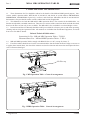
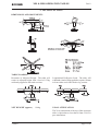
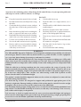
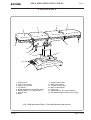
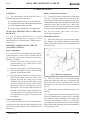
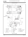
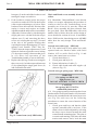
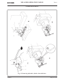
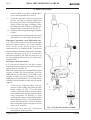
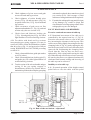
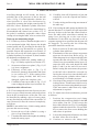
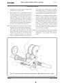
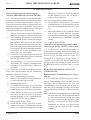
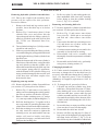
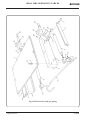
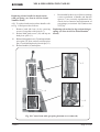
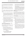
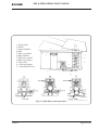
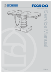
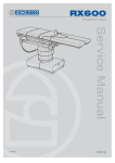
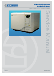
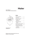
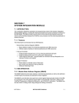
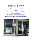
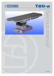
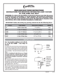
MR & MRS
OPERATION TABLE
Service manual
699255
T-SM5f
Eschmann After Sales Service Department
Preliminary
Technical data
Safety notes
Maintenance
The Eschmann After Sales Service Department is staffed and equipped to provide advice and
assistance during normal office hours. To avoid delays when making enquires, please quote the
Model and Serial Number of your Operation Table which is shown on the Serial Number plate, the
location of which is shown below. Please ensure you include all alpha and numeric digits of the
Serial Number.
The Serial Number
Plate is located on the
pedestal as indicated.
For further information visit www.eschmann.co.uk
All correspondence relating to the after sales service of Eschmann Equipment to be addressed to :
UK Customers
Eschmann Equipment, Peter Road, Lancing, West Sussex, BN15 8TJ, England.
Tel: +44 (0) 1903 765040. Fax: +44 (0) 1903 762006.
Overseas Customers
Service Manual
Contact your local distributor. In case of doubt contact Eschmann Equipment.
Trade marks
“MR” and “MRS” are trade marks of Eschmann Holdings Limited.
Copyright © 2001
All rights reserved. This booklet is protected by copyright. No part of it may be reproduced, stored in a
retrieval system or transmitted in any form or by any means, electronic, mechanical, photocopying,
recording or otherwise without written permission from Eschmann Holdings Limited.
The information in this publication was correct at the time of going to print. The Company, however,
reserves the right to modify or improve the equipment referred to.
If the CE mark is affixed to the product, it indicates compliance with Council Directive
93/42/EEC of 14 June 1993 concerning medical devices.
T-SM5f November 2001
MR & MRS OPERATION TABLES
READ THESE INSTRUCTIONS BEFORE USE
Keep these Instructions in a safe convenient place for future reference. Read in conjunction
with the relevant Publications detailed in the preliminary information section.
CONTENTS
Page
1. PRELIMINARY
..
..
..
..
..
4
2. TECHNICAL DATA
..
..
..
..
5
3. SAFETY NOTES ..
..
..
..
..
6
4. MAINTENANCE .. .. .. .. ..
General
.. .. .. .. .. .. ..
Cleaning, disinfection, care and storage ..
Periodic lubrication, checks & adjustment ..
Base Components .. .. .. .. ..
Castors and wheels .. .. .. .. ..
Brakes and brake mechanism .. .. ..
Hydraulic cylinder .. .. .. .. ..
Gears
.. .. .. .. .. .. ..
Hinge pin and nut .. .. .. .. ..
Lateral screw and nut
.. .. .. ..
Trend. screw assembly friction collars ..
Chair and Break screw assembly .. ..
Control arm - cable type .. .. .. ..
Control arm - gas spring .. .. .. ..
Emergency operation - MRS only .. ..
Head / Leg section and catches
.. ..
Fault diagnosis and remedies
.. .. ..
Excessive rotational movement of table top
Inability to raise table top .. .. .. ..
Table top not maintaining height .. ..
Operation table will not lower .. .. ..
Failure of control arm cable .. .. ..
Control arm - gas spring .. .. .. ..
Removal & installation of components
..
Replacement of trend, screw .. .. ..
Removing hydraulic cylinder from base ..
Replacing ram cup washer
.. .. ..
Removing and cleaning ball valve .. ..
Changing hydraulic oil .. .. .. ..
Replacing control arm cable .. .. ..
Replacing an antistatic wheel in base ..
7
8
8
8
8
8
8
8
10
11
11
12
14
14
14
16
16
17
17
17
18
18
20
20
20
20
21
21
21
21
22
22
T-SM5f
Page
Replacing castor
.. .. .. ..
Replacing worn brake pad
.. ..
Replacing brake quadrant .. .. ..
Replacing quadrant pinion
.. ..
Replacing broken quadrant pillar ..
Replacing main control handle
..
Replacing push-button catches.. ..
Replacing fine control handwheel ..
Replacing release handle/bar (old) ..
Replacing release handle (head new)
Replacing release bar (leg new)
..
Replacing gas spring (head/leg section)
Replacing gas spring (control arm) ..
Hydraulic system operation notes
..
..
..
..
..
..
..
..
..
..
..
..
..
..
..
22
22
23
23
23
23
24
25
25
27
28
28
28
28
ILLUSTRATIONS
Fig.1 MR Operation table (G.A.)
..
Fig.2 MRS Operation table (G.A.) ..
Fig.3 MR table - Parts and controls ..
Fig.4 Ram key adjustment .. .. ..
Fig.5 Base assembly .. .. .. ..
Fig.6 Gearbox of MR table .. .. ..
Fig.7 Hinge pin and nut adjustment ..
Fig.8 Lateral screw and nut adjustment
Fig.9 Releasing Trend. screw assembly
Fig.10 Trendelenburg screw assembly
Fig.11 Control arm (early MRS table)
Fig.12 Removing hydraulic cylinder ..
Fig.13 Hydraulic cylinder assembly ..
Fig.14 Ram release mechanism .. ..
Fig.15 Control arm cable replacement
Fig.16 Replacing a control handle
..
Fig.17 Catch mechanism for leg section
Fig.18 Head section without gas spring
Fig.19 Head section with gas spring ..
Fig.20 Control arm with gas spring ..
Fig.21 Hydraulic system operation ..
..
..
..
..
..
..
..
..
..
..
..
..
..
..
..
..
..
..
..
..
..
4
4
7
8
9
10
11
11
13
13
15
15
16
17
19
24
24
25
26
27
29
Page 3 of 29
Part 1
MR & MRS OPERATION TABLES
1. PRELIMINARY INFORMATION
1.1 These Instructions for Use should be referred to for details of the MR and MRS general purpose, foursection, mobile, operation tables, REF 80-085-15, 80-085-63 and 80-081-16 (serial numbers MRAB8E0000,
MRRB8E0000, MSAB8E0000 respectively, or above) and fixed base MR tables 80-085-92 and 80-085-96.
Information is also provided for earlier versions (within each section) if applicable.
1.2 This Manual covers both the MR and the MRS operation tables. The controls for the MRS tables are
fitted on an adjustable, extended control arm. There are two versions of the control arm which are both described,
however the later version only is now available. The MR table is also available in a reduced height version.
1.3 Instruction and Service Manuals should be readily accessible for reference prior to and when operating,
cleaning and servicing the Operation Table. All manuals are available from Eschmann Equipment, see inside
front cover for address details.
Related Technical Publications:Instruction for Use - MR and MRS Operation Tables - T-IM18
Illustrated Parts List - MR and MRS Operation Tables - T-IPL6
1.4 MR and MRS Operation Tables comply with BS6859 Part 1: 1987 (except for clause 7).
1.5 Fixed base tables should be serviced as conventional tables but check that the floor fixings are secure on
a regular (three month) basis, also check the antistatic resistor for function and connection and replace the base
seal if it becomes damaged..
Oil filler cap
Fig. 1 MR Operation Table : General Arrangement
Fig. 2 MRS Operation Table : General Arrangement
Page 4 of 29
T-SM5f
MR & MRS OPERATION TABLES
Part 2
2. TECHNICAL DATA
DIMENSIONS AND MOVEMENTS
TABLE LOADING
Retention of Adjusted Height: The table will
retain its adjusted height with a load of 135kg
uniformly applied to the trunk sections.
Longitudinal Deflection Load: The table will
withstand a load of 50kg applied at a point 150mm
in from either end of the head or leg section.
NET WEIGHT (approx)
X-RAY ATTENUATION
196kg
The X-ray attenuation of the top of this operation
table is equivalent to less than 0.5mm of 99.5%
pure aluminium.
T-SM5f
Page 5 of 29
Part 3
MR & MRS OPERATION TABLES
3. SAFETY NOTES
Attention to the following points will prolong the life and efficiency of your operating table and
will help to avoid the risk of accidents, or damage:
DO:
♦
Keep the instruction manual close-to-hand.
♦
Read the instructions carefully before using
the table.
♦
Check that the leg section is secure, and put
the table base in the brake position before
use.
♦
Raise the table top fully before washing the
table, to expose all the ram covers surface.
♦
Read and follow the instructions for cleaning,
and for the care of the mattresses and pads.
♦
Use the correct mattress and accessories.
♦
Service the table and accessories regularly.
♦
Remove table accessories and their clamps,
in particular rotary clamps from side bars,
when they are not in use.
DO NOT:
♦
Lift the table by its top.
♦
Push the table over rough surfaces, use a
trolley.
♦
Drop the table (or individual sections) when
transporting it.
♦
Put heavy weights on the table sections.
♦
Put sharp objects on, or against mattresses,
pads, or the radiographic table top.
♦
Drop heavy objects onto the radiographic
top.
♦
Spill oil, ether, or other chemical fluids onto
the mattress or the pads.
♦
Pull the table by the head or leg section,
always push it.
♦
Exceed maximum table loading
WARNINGS
The MR and MRS Operation Tables have been designed to minimise the possibility of accidental
electrosurgery burns. Contact with any metal surfaces (e.g. table side bars, or other equipment
etc.) can cause burns during electrosurgery and must be avoided.
The MR and MRS Operation Tables have been designed for patients weighing up to 135kg with
their centre of gravity (normally the perineum) over the base. However patient positioning and
additional loads can compromise table stability. Ensure that loading does not compromise table
stability.
With the table in (or during transition into) the castor position, the centre of gravity of the
patient (normally the perineum) should lie over the centre of the column . Whenever this is not
practical the overhanging weight of the patient and table should be adequately supported (e.g.
by at least two able people). Take extreme care when moving a table with a patient on and
ensure that the table is at minimum height
The patient’s weight should be supported whenever the sections are adjusted or removed from
the table during repositioning.
The head and leg sections are designed to support and position the appropriate part of the
patient’s weight only. Damage leading to failure of the section may be caused if excessive weight
is applied. Also do not sit or lean on the control arm of the MRS table.
The maximum loading weight of 10kg must not be exceeded for the Detachable ophthalmic head
flap and the Non-Detachable head flap accessories, as this may cause damage to the accessory
and could result in injury to the patient.
It is necessary to check at regular intervals for wear, corrosion, material fatigue and ageing on
all accessories which support all or part of the body of the patient using a single gas spring. Such
accessories are the detachable ophthalmic head-flap and head-flap.
Page 6 of 29
T-SM5f
Part 4
MR & MRS OPERATION TABLES
4. MAINTENANCE
4
3
2
1
5
6
15
14
13
7
12
11
10
9
8
1
2
3
4
5
6
7
8
Head Section
Upper Trunk Section
Lower Trunk Section
Leg Section
Quick-release Bar (Leg Section Angle)
Release Button, L.H. (Leg Section)
Oil Filler Cap
Base
9
10
11
12
13
14
15
Height Control Pedal
Base Control Pedal
Cylinder Locking Lever
Main Control Handle
Gear Lever
Release Button, R.H. (Head Section)
Quick Release Bar (Head Section Angle)
Fig. 3 MR Operation Table : Part identification and controls
T-SM5f
Page 7 of 29
Part 4
MR & MRS OPERATION TABLES
4. MAINTENANCE
GENERAL
Brakes and brake mechanism
4.1 The information provided in this Service
Manual falls into four categories:
♦ Cleaning, Disinfection, Care and Storage.
♦ Periodic lubrication, checks and adjustments
♦ Fault diagnosis and remedies
♦ Removal and installation of components
4.5. Check the action of the brake mechanism
(see Fig. 5) and also check for wear on the brake
pads, broken brake pinion or quadrant teeth, play
in the quadrant taper pins and adjustment between
quadrant, roller and eccentric pin. Check stop
screws for wear. To replace quadrant see section
4.44; to replace quadrant pinion, see section 4.45.
CLEANING, DISINFECTION, CARE AND
STORAGE
4.6 Fit new brake pads where necessary,
referring to section 4.43.
4.2 For Cleaning, Disinfection, Care and
Storage instructions refer to Section 8 of the
Instructions for Use (Publication T-IM18, also see
section 1.3).
Hydraulic Cylinder
PERIODIC LUBRICATION, CHECKS
AND ADJUSTMENTS
4.7 Raise the table top to its maximum height,
then depress the height adjustment (hydraulic
pump) pedal fully and check for smoothness and
rate of descent.
Base Components
4.3 In order to carry out maintenance procedures
to the table base, it is necessary to tilt the table on
its side and expose the underside of the base.
Proceed as follows:
i
Remove the head and leg section in the
normal manner (see Instruction for Use,
Publication T-IM18).
ii Raise the table top to its maximum height.
iii Place an anaesthetist’s stool, or similar strong
support, alongside the table.
iv Place the brake pedal in the ‘castor’ position.
v Stand on the same side of the table as the
support but with the pump lever on the
opposite side. Push the table away about
30 cm and then pull it back. This ensures
that all the castors are pointing away from
the operator. Two people on the same side of
the table as the support (one at each end) can
now each place a foot against the base and
lever the table over gently, lowering it onto
the support.
Castors and wheels
4.4. Clean each castor (see Fig. 5) and wheel free
of debris, then lubricate the castor and wheel ball
races with a light machine oil (or WD40 aerosol
lubricant).
Page 8 of 29
Fig. 4 Ram key adjustment
4.8 Raise the table top to its maximum height
again and release the ram cover securing screws
at the top. Refer to Fig. 4 and lower the 3-section
telescopic cover (1) to expose the ram (2) and ram
key (3).
4.9 Remove the ram key, clean out keyway and
refit key.
4.10 Examine ram surface for rust and, if present,
clean off with fine emery cloth. (Note: Later rams
have a black surface coating do not confuse this
with rust and attempt to remove it). Lubricate
exposed surface of ram. Seal the top of the cylinder
with cloth wound round the ram to prevent damage
if using emery cloth.
T-SM5f
Part 4
MR & MRS OPERATION TABLES
4. MAINTENANCE
DETAIL A
DETAIL C
DETAIL B
1.
2.
3.
4.
5.
6.
7a/b.
Base casting
8.
Base cover
9.
Castor frame
10.
Castor
11.
Castor mounting screw 12.
Wheel
13.
Grub screws
14.
Wheel spindle
Base control pedal
Brake pad screws
Brake pad
Stop screw
Pinion
Quadrant
15.
16.
17.
18.
19.
20.
Oil sump
Roller
Quadrant securing nuts
Brake shaft collars
Eccentric pin
Quadrant pillar
Fig. 5 Base assembly
T-SM5f
Page 9 of 29
Part 4
MR & MRS OPERATION TABLES
4. MAINTENANCE
4.11 Before refitting ram cover, check that table
will raise and lower smoothly. If this is not the
case, the ram key is probably secured too tightly.
Release the key attachment bolts (4) slightly to
remove excessive friction, then retighten.
4.12 Check for signs of oil leaks. If table will
not pump to its full height, refill reservoir with
the Eschmann oil supplied with the table, in small
measures, lowering the table after each addition.
This will avoid the risk of introducing too much
oil into the hydraulic system.
1.
2.
3.
4.
5.
6.
7.
8.
Main control handle
Gear selector lever
Selector shaft
Trendelenburg idler gear
Break idler gear
Gear selector unit
Selector gear, lateral tilt
Break screw and gearbox (left hand)
Gears
4.13 Check function of gear selector lever in
conjunction with main control handle and ensure
that each table top movement is satisfactorily
achieved. Check to see if there is any excessive
play in table top in any particular direction (see
section 4.14 and 4.15). This applies particularly
to the two grub screws (4, Fig. 10) securing
screwed bush to screw housing on Trendelenburg
and Break screw assemblies. Check friction collar
adjustment on Trendelenburg and Break screw
gears (see sections 4.16-4.19); also check that
9.
10.
11.
12.
13.
14.
15.
Pivot gear, lateral tilt
Drive gear, lateral tilt
Gear shaft
Drive gear, break
Drive gear, Trendelenburg
Trendelenburg screw and gearbox
Break screw and gearbox (right hand)
Fig. 6 Gearbox of MR operation table
Page 10 of 29
T-SM5f
MR & MRS OPERATION TABLES
Part 4
4. MAINTENANCE
gears on the idler plate (Fig. 6) still have clearance
and that securing screws are tight on driving and
idler gears in main gear train. Check grub screw
securing pivot bolt.
Hinge pin and nut
4.14 Pull table top as shown in Fig. 7 to check
for excessive play in the direction of the arrows.
If there is excessive play present refer to Fig. 7
and check to see if hinge nut (1) and bolt (2) are
loose. If so, * tighten hinge nut (1) against hinge
bolt (2) sufficiently to take up the slackness. To
do this, Eschmann recommend using two short
lengths of 3/16 in. diameter round bar (3) inserted
in the nut sockets, as illustrated in Fig. 7 and
applying an improvised tommy bar (4) to turn the
nut.
Lateral screw and nut
4.15 Place table top in reverse Trendelenburg
position, then select Lateral Tilt and operate
control handle to test movement is satisfactory.
Pull as shown in Fig. 8. If undue play is suspected
refer to Fig.8 and proceed as follows:
i
Check secureness of link pivot set screws
(6) and (7).
ii Check secureness of grub screw on yoke (5)
which locks lateral screw bearing.
CAUTION: Do not over-tighten.
*Note: This could also indicate play in
Trendelenburg gear. If this is the case the complete
Trendelenburg screw assembly must be replaced.
For adjustment, see sections 4.16-4.18.
Detail ‘A’
Detail ‘B’
Fig 8 Lateral screw and nut adjustment
iii
Sectional view in direction ‘A’
Fig. 7 Hinge pin and nut adjustment
T-SM5f
Finger testing at the point where the lateral
screw (1) passes through the nut (2) will
establish the need for the nut adjustment.
First try tightening socket head screws (3)
on nut. If excessive play is still present,
shim removal will be necessary. Proceed as
follows:
(a) Unfasten socket head screws (3) on nut
and extract shim pack (4).
(b) Remove shims (0.002 in thickness per
shim, approx.) one at a time until play
is just taken up on re-tightening.
Page 11 of 29
Part 4
MR & MRS OPERATION TABLES
4. MAINTENANCE
Trendelenburg screw assembly friction
collars
NOTE: Sections 4.16 and 4.17 should only be
referred to for tables with serial numbers
preceding those detailed below, for later tables or
tables that have had the latest Trendelenburg
screws fitted refer to section 4.18.
Tables with serial numbers as detailed below have
the latest Trendelenburg screw fitted and section
4.18 applies :MR
- 2060 (or above)
MRS - 1177 (or above)
4.16 Adjustment of the friction collars on the
Trendelenburg screw MUST be checked regularly.
If the table does not easily stay in Trendelenburg
or reverse Trendelenburg position, but tends to
slip down under patient’s weight, this indicates
that the Tufnol friction collars (9, Fig. 10) need
tightening. Proceed as follows:
i
Remove the leg section as described in the
Instruction Manual and then pump the table
top to maximum height with the height
adjustment pedal.
ii Elevate the head section to the maximum
raised angle and place the table in maximum
reverse Trendelenburg position.
iii Remove the gearbox cover (3, Fig. 9).
iv Bolster the table top in position as shown in
Fig. 9 and then free the lower end of the
Trendelenburg screw assembly (1, Fig. 9)
by removing the pivot screws (2, Fig. 9).
v Pivot the Trendelenburg screw assembly
about its bevel gear housing (4, Fig. 9) to
gain access, in turn, to the four screws
(5, Fig. 9) holding the two halves of the
housing together. Remove the four screws
to separate the two half housings and remove
the Trendelenburg screw assembly, with the
bevel gear lower half housing from the
table.
vi Refer to Fig. 10a. Mark the bevel gear lower
half housing (3) and screwed bush (12) to
aid reassembly, then remove socket head
grub screws (4) from the half housing and
unscrew the screwed bush (12) until heads
Page 12 of 29
of friction collar grub screws (11) are
exposed.
vii Tighten grub screws (11), securing friction
collars (9), to a torque of 16 to 17 lbf in.
viii Screw screwed bush (12) into the half
housing and secure with socket head grub
screws (4).
ix Using a suitable torque wrench (e.g. Torque
driver-Part No. 759581 and 4mm Bit-Part
No. 759582), attached to nut (17) using
adaptor (Part No. 759566), check final
friction of screw shaft (15); the torque
required to turn screw shaft (15) should be
between 30 and 35 lbf in. If final friction
torque cannot be achieved, further tighten
each friction collar grub screw (11), by 1 to
2 lbf in. per occasion until 30 to 35 lbf in.
torque is achieved. If torque figure is not
achieved by a maximum setting of 20 lbf in.
then refer to section 4.17.
4.17 If further friction cannot be obtained by
carrying out the above procedure, the friction
collars are worn and a new Trendelenburg screw
assembly should be fitted. Refer to section 4.34
under REMOVAL AND INSTALLATION OF
COMPONENTS.
4.18 For tables having the latest design of
Trendelenburg screw assembly (see note
preceding 4.16) the adjustment of the friction
collar on the Trendelenburg screw MUST be
checked regularly. If the table does not easily stay
in Trendelenburg or reverse Trendelenburg
position, but tends to slip down under patient’s
weight, this indicates that the friction collar needs
adjusting. Refer to Fig. 10b and proceed as
follows:
i
Remove the leg flap and place gear lever in
Lateral Tilt position.
ii Unscrew sleeve cap (1) and remove the end
cap tubes (2) from the Trendelenburg screw
assembly.
iii Using torque screwdriver (Part No. 759581
set to 20-25 lbf.in. and fitted with adaptor
T2095 Part No. 759653 and 20mm socket),
check the setting by locating socket over the
T-SM5f
MR & MRS OPERATION TABLES
Part 4
4. MAINTENANCE
View on Trendelenburg screw bevel
gear - half cover removed.
Fig. 9 Releasing Trendelenburg screw assembly
(* To determine which Trendelenburg screw is
fitted to a table, see note preceding section 4.16)
Fig. 10a Early* Trendelenburg screw assembly
(* To determine which Trendelenburg screw is
fitted to a table, see note preceding section 4.16)
Fig. 10b Later* Trendelenburg screw assembly
T-SM5f
Page 13 of 29
Part 4
MR & MRS OPERATION TABLES
4. MAINTENANCE
iv
v
vi
hexagon (3) on the end of the leadscrew and
turning the torque screwdriver.
If the leadscrew rotates before the torque
screwdriver reaches 20-25 lbf.in. the friction
collar requires adjusting as (v) below. If the
leadscrew does not rotate the friction collar
setting is correct and requires no further
adjustment and the table can be reassembled.
Adjust the friction collar by slackening the
single grub screw (4) that locks the torque
adjuster nut (5) and removing the three
screws (6) securing the cap ring (7) located
at the rear of the gearbox housing thus
exposing the torque adjusting nut (5). Locate
spanner (tool number T2097 Part No.
759652) onto the torque adjuster nut (5) and
tighten or slacken to gain the correct setting
(i.e. the torque setting is between that given
in (iii) above but operation of the
Trendelenburg handle is not too difficult).
Replace the cap ring (7) and secure using the
three screws (6), lock the torque adjuster nut
(5) by tightening the single grub screw (4)
and reassemble the table.
Chair and Break screw assembly friction
collars
4.19 Should the ‘Chair and Break’ screw friction
collars ever require adjustment, the procedure is
similar to that for the Trendelenburg screw
assembly (see 4.16 to 4.18), once the ‘Chair and
Break’ screw assembly has been released from
the gear shaft. (Note that MR tables with serial
number 2099 or below have the earlier design of
screw detailed in sections 4.16 to 4.18 and tables
above 2099 have the latest design screw. All MRS
tables have the early design ‘Chair and Break’
screw).
Control arm (cable type) - MRS only
4.20 The control arm of early tables were cable
operated and were fitted to tables with Serial
Number 1023 or earlier. Refer to Fig. 11 and
remove the control arm cover, then:
i
Check chain links (1)
ii Check gears and keys (2)
iii Ensure lubrication of cable (3)
iv Check cable bends and cable nipples (4)
(also see Fig. 15).
Control arm (gas spring type) - MRS only
WARNING
Gas springs are filled with
high pressure gas.
DO NOT ATTEMPT TO OPEN THEM
Fig. 11 Control arm (early MRS table)
Page 14 of 29
CAUTION
Gas springs MUST NOT be
additionally lubricated.
4.21 Gas spring operated control arms have been
fitted to tables from Serial Number 1024 onwards.
Remove the extended head end control arm cover
(see Fig. 20) and carry out the following
procedures to ensure the correct function of the
control arm.
i
Check gears and keys and that the chain
operates smoothly and is not loose. If the
chain is loose it can be adjusted by releasing
the three screws located around the main
control handle mounting plate. This plate is
eccentric and rotating it will alter the chain
tension and remove slack, lock the main
T-SM5f
Part 4
MR & MRS OPERATION TABLES
(A)
(C)
(D)
(B)
4. MAINTENANCE
Fig. 12 Removing hydraulic cylinder from table base
T-SM5f
Page 15 of 29
Part 4
MR & MRS OPERATION TABLES
4. MAINTENANCE
ii
iii
iv
control handle in position with the three
screws when adjustment is correct.
Check the operation of the gas spring and
look for any signs of leakage. Replace the
gas spring (see section 4.59) if performance
is poor or there are signs of leakage. (Note
the Warnings and Cautions regarding gas
springs between sections 4.20 and 4.21).
Lubricate all moving parts using part number
670010.
On completion of routine checks on control
arm replace cover and check all functions.
Emergency operation - early MRS table only
4.22 This section only refers to tables with cable
operated control arms (i.e. pre Serial Number
1025). Refer to the latest version of the
Instructions for Use, Publication No. T-IM18 and
place the table in emergency operation. Check that,
with the emergency gear lever in the three
alternative positions, the table top will move in
the corresponding directions by use of the main
control handle.
Head/leg section and catches
4.23 Proceed as follows for old style sections
without gas spring supports, for sections with gas
springs refer to section 4.24.
Note: Gas spring supports were not fitted to head
sections of tables pre Serial Number 1026 for
MRS and pre Serial Number 676 for MR, or leg
sections of tables pre Serial Number 1017 for
MRS and pre Serial Number 315 for MR. Tables
with these Serial Numbers or later have gas spring
supports.
i
Clean out any collected debris from the
recesses of the locking and guide pin push
button catches (4, Fig. 17) in the trunk
sections of the table. Refer to section 4.49 to
4.52 and dismantle each push button check
each component for damage or wear
replacing as necessary, Check spring-loaded
nylon plungers (2, Fig. 17) for smooth action.
Clean and lubricate the catch mechanism
then reassemble (again referring to section
4.49 to 4.52.) and test.
ii Lubricate rack and fine adjustment
movement of head/leg section.
Page 16 of 29
Fig. 13 Hydraulic cylinder assembly
T-SM5f
MR & MRS OPERATION TABLES
Part 4
4. MAINTENANCE
iii
iv
v
vi
Check tightness of pivot screws and grub
screws on head and leg sections.
Check tightness of socket headed pivot
screws (5, Fig. 18) and cap nuts (4, Fig. 18)
on quick release bar (3, Fig. 18) on head and
leg sections.
Check secureness of grub screw on fine
adjustment handwheel (1, Fig. 18) on head
section only (also see section 4.53).
Check clean and lubricate locking pin
(7, Fig. 18) and guide pin (8, Fig. 18) with a
light machine oil on head and leg sections.
4.24 For tables with head and leg sections
incorporating gas spring supports (see note in
section 4.23 above for the Serial Numbers of tables
that do) refer to Fig. 19 and proceed as follows
noting WARNINGS and CAUTIONS preceding
section 4.21:
i
Check, clean and lubricate guide pin catches
as 4.23(i) above.
ii Check clean and lubricate locking pin (23)
and guide pin (25) with a light machine oil
on head and leg sections
iii Test the action of the release handle and gas
spring. If the gas spring support is
unsatisfactory (head or leg section fails to
maintain its position) the complete gas spring
iv
unit must be replaced, they cannot be serviced
(see section 4.58). Also seepage of fluid
indicates a failing unit that must be replaced.
Examine the radiographic top panel for signs
of any damage (e.g. cracks or chips) and
check that the securing spring collars of the
radiographic top are not damaged.
FAULT DIAGNOSIS AND REMEDIES
Excessive rotational movement of table top
4.25 Rotational movement of the table top is
controlled by the tapered ram key (3, Fig. 4).
Excessive movement is due to wear of the ram
key increasing the clearance in the keyway. This
can be corrected by slightly loosening the ram key
clamping bolts (4, Fig. 4), gently tapping the key
into the keyway until excess movement has been
removed and retightening the clamping bolts.
Check that the ram key has not been overtightened by fully raising and lowering the table
top. If the table top will not raise or lower correctly,
the ram key has been over-tightened and must be
slackened until normal raising and lowering of
the table top can be achieved.
Inability to raise table top
4.26 If normal operation of the height control
pedal fails to raise the table with the pedal
Fig. 14 Ram release mechanism - adjustment
T-SM5f
Page 17 of 29
Part 4
MR & MRS OPERATION TABLES
4. MAINTENANCE
travelling through its full stroke, the fault is
probably due to the presence of dirt in the ball
valve, (1, Fig. 13) of the hydraulic cylinder. It is
often possible to clear this obstruction by
vigorously operating the height control pedal. If
this fails, remove hydraulic cylinder from base
(see section 4.35); the ball valve should then be
disassembled and cleaned (see section 4.37). If
the pedal is suddenly inoperable either when
raising or lowering the table, refer to section 4.28.
Table top not maintaining height
4.27 If table top fails to maintain height, raise it
to its maximum height, fully depress the height
control pedal and, by pressing on the table top,
force the table top downwards as quickly as
possible. Repeat this operation several times. If
this does not rectify the fault remove hydraulic
cylinder from base (see section 4.35) then examine
the hydraulic mechanism for:
i
Condition of ball valve jointing washer (2,
Fig. 13). If faulty, replace it (see section 4.37).
ii Secureness of ram cover plate (3, Fig. 13). If
it is loose, retighten it.
iii Efficiency of ball valve (1, Fig. 13). If
blocked or jammed, disassemble and clean
it, (see section 4.37). If the seating of the
larger (spring-loaded) ball has been
damaged, replace the complete valve.
iv Condition of ram cup washer (4, Fig. 13). If
worn or chipped, replace it (see section 4.36).
Operation table will not lower
4.28 First examine the steel ram for rust (see note
below); a type of black rust not easily noticed can
form on the circumference of the ram. This can
be identified by rubbing a piece of emery paper
on any discoloured portion of the ram surface. If
rust is detected, it must be removed completely,
as follows:
NOTE: Later tables have a black coating which
prevents this rust occurring.
i
Protect the top of the cylinder by tying a
piece of rag around the ram.
ii Clean the ram surface thoroughly by rubbing
hard with emery paper.
Page 18 of 29
iii
iv
Carefully clean off all particles of grit and
completely cover the exposed ram surface
with oil.
Test the raising and lowering movement of
the table top.
4.29 If on testing the table pump mechanism for
normal function it is found to be still inoperable
this may be due to the fact that efforts made to
lower the table while seized have strained the
pump lever driving pin or the ram release
mechanism. If the table top descends at all in
response to pump lever operation, the descent will
be sluggish. To remedy this the following
procedure should be carried out:
i
Refer to section 4.35 and remove hydraulic
cylinder from table base.
ii Examination of the ram release movement
must now be carried out. Refer to Fig. 14.
When the pump lever is depressed fully, this
operates the ram release lever (1). The ram
release lever pivots and the release screw (2)
enters the ball valve and should lift both
balls (3 and 6) at the end of lever travel.
Before testing this movement, the pressure
in the ball valve should be overcome by
forcing the release lever into the ball valve
after covering the cylinder with a cloth to
avoid leakage of oil under pressure.
iii Now depress the pump lever fully and hold
in this position. Test the ram release lever by
trying the movement using thumb pressure.
If the movement is other than very slight,
adjustment is required.
4.30 To adjust ram release mechanism, proceed
as follows:
i
Position the compression tool clamp
(included in the tool kit available for the MR
series tables, Part No. 751030) across the
base of the cylinder (see Fig. 12c) and lightly
tighten it onto the ram release. Use an Allen
key to remove the four screws holding the
ram release in position.
ii Loosen the clamp until oil starts to run from
the hole. Allow the oil to drain.
iii Continue to unscrew the clamp until
T-SM5f
Part 4
MR & MRS OPERATION TABLES
4. MAINTENANCE
completely loose then remove clamp and
ram release (see Fig. 12(d)).
iv Refer again to Fig. 14. Adjustment consists
of unscrewing, in a clockwise direction, the
two large lock nuts (4) on the end of the
release plunger (5) to allow more movement
of the ram release lever. This is in order to
cause the ball of the ball valve to be lifted
further and so release the table ram. (For a
more detailed explanation of the hydraulic
system, refer to section 4.60 and 4.61).
Note:This adjustment can only be made on a trial
and error basis. Each time an adjustment is
made the ram release must be refitted into
the cylinder and the pump lever tried and
held to ascertain whether the release screw
on the lever projects too far into the ball
valve, or still not enough. Care must be
taken to adjust this correctly as strain will
occur either side of the normal. As a guide,
the normal setting is 1/16in between release
screw and ball valve housing (approximately
the thickness of an engineer’s steel ruler).
v When the correct adjustment has been made,
lift the cylinder and table top bodily and
guide the cylinder back into the well of the
base. DO NOT ALLOW THE CYLINDER
TO DROP INTO THE BASE. When the
table is in an upright position and before
lowering it into the base, refit the locking
lever. This will prevent the escape of oil
from the cylinder. The table top should now
raise and lower normally.
Note:If it is found that the driving pin of the pump
pedal has been bent - too badly for any
adjustment - a new pump lever must be
fitted.
Fig. 15 Control arm cable adjustment/replacement - MRS table pre Serial No. 1024
T-SM5f
Page 19 of 29
Part 4
MR & MRS OPERATION TABLES
4. MAINTENANCE
Failure of cable operated control arm gear
selection, MRS table only (pre Serial No.1024)
4.31. The control arm gear lever operates the table
top movement selection mechanism in the gearbox
by means of a flexible cable assembly (3, Fig. 11).
If movement selection fails to function correctly
while the table is in use, immediate action must
be taken to engage the standby controls. The fault
symptoms can be any of the following:
i
The gear selector lever may have been struck
and bent, causing gear selection to be upset.
ii Trendelenburg movement is permanently
engaged but the gear lever does not spring to
this position when placed in the vertical
gate. This indicates that the ferrule at either
end of the inner cable has been sheared-off,
in which case the cable assembly should be
renewed or the ferrule resoldered to the
inner cable (see section 4.40).
iii Lateral tilt or flexion/extension movement
is not engaged when the gear lever is moved
into the appropriate position.
iv Trendelenburg and flexion/extension
movements are engaged simultaneously
when the gear lever is in either of these two
positions.
4.32. Symptoms (iii) and (iv) indicate that the
inner cable has stretched and the mechanism
should be adjusted as follows:
i
Select Trendelenburg movement.
ii Refer to Fig. 15 and locate adjusting screw
(1) beneath upper trunk section.
iii Slacken thumb nut (2).
iv Check that selector gears (3) and (4) slide
freely on the main shaft (5) and that the
return springs (6) and (7) function correctly.
v Check that the selector gear (3) is in full
mesh with the idler gear (8); if necessary
turn the adjusting screw (1) in the direction
required to achieve this condition.
vi Select lateral tilt movement.
vii Check that the selector gear (4) is in mesh
with the drive gear (9) and that the selector
gear (3) is completely disengaged from both
Page 20 of 29
idler gears (8) and (10). Small adjustments
to the adjusting screw may be made to
achieve these conditions.
viii Select chair and break movement.
ix Check that the selector gear (3) is in mesh
with the idler gear (10) and that the selector
gear (4) is disengaged from the drive gear
(9).
x Repeat the checks (5) to (9) with the control
arm in two or three different positions,
making small adjustments to the adjusting
screw if necessary to establish the optimum
setting.
xi Tighten the thumb nut.
Control arm not maintaining position (MRS
table with gas spring, Serial No. 1024 or later)
4.33 If the control arm will not maintain its
position this is normally indicative of a faulty gas
spring. Remove the lower control arm cover (as
shown in Fig. 20) and check for signs of a
damaged or a leaking gas spring, replace if
required, see section 4.58. Do not lubricate gas
springs and do not attempt to repair them (see
WARNINGS and CAUTIONS above section
4.21).
REMOVAL AND INSTALLATION OF
COMPONENTS
Replacement of Trendelenburg screw (Fig. 9
and 10)
4.34 To replace the Trendelenburg screw, remove
the old Trendelenburg screw assembly from the
operation table as detailed in 4.16. Fit a new
Trendelenburg screw assembly (latest style see
note above 4.16) and adjust it to the correct torque
setting as detailed in section 4.18. Reassemble the
table.
Note: The bevel gear housing has one thick and
one thin side wall. The thin side wall should
be fitted round the neck of the gear shaft
bevel gear. Ensure that the upper bevel gear
housing is orientated to match before
attempting to refit the cap head screws
securing the two halves of the housing
together.
T-SM5f
Part 4
MR & MRS OPERATION TABLES
4. MAINTENANCE
Removing hydraulic cylinder from table base
4.35 Due to the weight of the assembly, three
persons will be required for this operation.
Proceed as follows:
i
Remove the head and leg sections and, if
possible, lower the table top to its lowest
position.
ii Refer to Fig. 12 and remove plate (1) from
cylinder base cover and secure into the
exposed tapped hole the lifting eyebolt (2)
which is provided in the table tool kit Part
No. 751030 (see Illustrated Parts List,
T-IPL6).
iii Turn cylinder locking lever (3) fully counterclockwise and remove it.
iv With one person holding the lifting eyebolt,
a second holding the pump pedal and a third
steadying the table top, lift the cylinder from
the table base.
v When the bottom end of the ram cylinder is
lifted clear of the table base, swing the table
top and cylinder so that the cylinder (4) is
almost horizontal then lay the table top onto
a low support, pump pedal (5) uppermost,
with the bottom of the cylinder resting on a
strong wooden batten placed across the well
of the base; this will allow surplus oil to
drain into the base.
v
Refit cover plate (3) and sealing gasket (8),
then manhandle table into base ensuring,
before doing so, that the cylinder locking
lever (3, Fig. 12) is refitted.
Removing and cleaning ball valve
4.37. Remove hydraulic cylinder from table base
(see section 4.35) then proceed as follows:
i
Refer to Fig. 13 and remove ram release
lever pivot (9) - Sellok pin or screwed pin
and lock nut - then remove ram release
lever.
ii Unscrew the four ball valve retaining screws
(10) and insert two of these screws into
tapped holes in valve flange.
iii Continue to turn retaining screws until valve
assembly is forced from its seating.
iv Disassemble ball valve assembly and
thoroughly clean all components in a suitable
solvent.
v Reassemble and refit ball valve, preferably
using a new jointing washer (2).
Changing hydraulic oil
Replacing ram cup washer
4.38 Under normal circumstances it will not be
necessary to change the oil in the table base for
ten years. After that time change the oil, using 2.8
litres (5.0 Imperial pints) of the Eschmann
(Matburn) oil supplied (equivalent to SAE 30
motor oil).
4.36 Remove hydraulic cylinder from table base
(see section 4.35), then proceed as follows:
i
Refer to Fig. 13 and remove cover plate (3)
taking care not to damage the sealing gasket;
the ram cup washer will then be exposed.
ii Remove washer retaining screw (6), washer
(11), ram cup washer (4) and backing disc (7).
iii Refit the backing disc (7) together with a
new cup washer (4) smearing the latter with
a little of the oil used for the table hydraulics.
iv Refit the retaining screw and its washer but
use only moderate tension to tighten the
retaining screw; too much and the ram cup
washer will tend to buckle and allow
peripheral oil seepage - too little and oil will
leak past the backing disc.
4.39 To change the oil, proceed as follows:
i
Lift table top and ram cylinder away from
table base, as described in section 4.35 then,
after draining off excess oil from cylinder
back into table base, remove table top and
cylinder assembly and lay it on its side. (Do
not stand the assembly on the bottom of the
cylinder as this will damage the relief valve
mechanism).
ii Invert table base to empty out all the oil and
clean out the oil reservoir thoroughly.
iii Reassemble the table into its base.
iv Remove oil filler cap and pour 2.8 litres (5
Imp. pints) of the hydraulic oil supplied into
the sump via the oil filler (7, Fig. 3). To do
this effectively, the oil should be added little
T-SM5f
Page 21 of 29
Part 4
MR & MRS OPERATION TABLES
4. MAINTENANCE
by little and the table raised and lowered
via the pump pedal after each addition until
full table movement can be achieved. This
method ensures that excess oil is not
introduced.
Removing and replacing control arm cable
assembly - MRS table only pre Serial No. 1024
4.40 Proceed as follows:
i
Remove table head section in the normal
manner as described in the table Instruction
for Use.
ii Adjust position of control arm to a
convenient working position and remove
the socket head screws from the top cover.
Lift away top cover.
iii If the ferrule at one end of the inner cable has
sheared-off, the inner cable will be loose
and the opposite end may be disconnected
from its control arm pivot (5, Fig. 11) or
cable pivot (12, Fig. 15).
iv Withdraw outer cable from cable holder
(6, Fig. 11) and from the adjusting screw
(1, Fig. 15. Remove cable assembly from
control arm.
v If a new cable is not to be fitted, soft-solder
the loose ferrule to the end of the inner cable.
Carefully restore the contour of the ferrule
(4, Fig. 11)
vi Feed the cable assembly through the control
arm.
vii Pass the ferrule (4, Fig. 11) through the
cable holder and locate the end of the outer
cable in the holder.
viii Pass the ferrule at the opposite end through
the adjusting screw (1, Fig. 15) and locate the
end of the outer cable in the adjusting screw.
ix Connect the ferrule to the cable pivot
(12, Fig. 15).
x Check that the standby gear lever is located
in the Trendelenburg position.
xi Move the extended control gear lever to the
lateral tilt position.
xii Press the selector lever (13, Fig. 15) to the
left.
Page 22 of 29
xiii Connect the ferrule (4, Fig. 11) to the control
arm pivot (5, Fig. 11).
xiv Assemble the control arm top cover and tighten
the securing screws.
xv Refit the head section.
xvi Adjust the cable assembly (see section 4.32).
Replacing antistatic wheel in table base
4.41 Refer to section 4.3 and tilt table with pump
pedal uppermost and wheel to be removed
uppermost, then proceed as follows:
i
Refer to Fig 5 and withdraw grub screw (7a)
just sufficiently to be able to tap out the
domed wheel spindle (8) from the inside,
while still retaining the bush in position.
ii Slacken grub screw (7b) then fit
replacement antistatic wheel with original
domed spindle. Adjust position of bush
under grub screw (7b) to accommodate
width of new wheel, then retighten grub
screw (7a) into the dimple of the spindle.
iii Finally, tap the inside bush under grub screw
(7b) to make a close fit against the wheel
and then tighten grub screw (7b).
Replacing castor
4.42 The castor assembly is available with aluminium
or antistatic rubber wheels and comes complete with
yoke, wheels, washers, spindle and spindle securing
nut. Individual wheels are also available. To replace
a damaged castor, refer to section 4.3 and tilt the
table with the pump pedal uppermost and the castor
to be removed uppermost, then refer to Fig. 5 and
remove the four set screws (5) and release the castor
mounting plate from the table base. Note: When
replacing a castor assembly (or just the wheels) ensure
that the wheels are identical to the original ones (i.e.
polyurethane, antistatic rubber, or aluminium). The
wider ‘single’ aluminium wheels have been
discontinued, only the ‘narrow double wheels’ are
available. It may be necessary to fit new castor
assemblies and then change the wheels to polyuethane.
Replacing worn brake pad
4.43 Tilt the table to expose the base underside
(see section 4.3) then proceed as follows:
T-SM5f
Part 4
MR & MRS OPERATION TABLES
4. MAINTENANCE
i
ii
Note the direction of tread pattern of the worn
pad (11, Fig. 5), before removing pad.
Remove the two hex screws (10, Fig. 5)
securing brake pad to frame and install new
pad, with the tread pattern facing in the same
direction as that noted in (i) above.
Replacing brake quadrant
4.44 If the base control pedal movement is uneven
and jerky the quadrant teeth may be damaged. This
can be ascertained by feeling with the fingers under
the table base. Tilt the table to expose the base
underside (see section 4.3) then proceed as follows:
i
Refer to Fig.5 and remove socket head stop
screw (12) from beneath cut-out end of
quadrant (14).
ii
Turn the quadrant clear of the roller (16)
remove hex. nuts (17) and withdraw the
quadrant. If quadrant teeth are broken, fit
new quadrant. For renewal of quadrant
pinion, carry out the procedure detailed in
the following paragraph.
vii
Locate base control pedal shaft in table base
with collars and spring, and secure collars
in correct position. Install pinion on end of shaft
and fit taper pin.
viii With base control pedal in ‘castor’ position (see
diagram on base instruction plate) install
quadrant between roller (16) and eccentric pin
(19). Ensure that quadrant and pinion mesh
correctly and that the base control pedal is
parallel with the base instruction plate in the
‘wheel’ position, before fitting stop screw (12)
to quadrant. Check that brake pads are just
clear of the floor in the ‘wheel’ position.
ixThe eccentric pin (19) should be adjusted to take
up any excessive play between quadrant and
roller.
Replacing broken quadrant pillar
4.46 Proceed as described in section 4.44 to
remove quadrant, then remove and replace broken
quadrant pillar (20, Fig. 5). Reassemble
components.
Replacing quadrant pinion
Replacing main control handle
4.45 Symptoms of jerky movement on base
control pedal could also be due to broken quadrant
pinion teeth. Verify as section 4.44 for broken
quadrant. Tilt the table to expose the base
underside (see section 4.3) then proceed as
follows:
i
Remove quadrant (see section 4.44).
ii Refer to Fig 5 and turn base control pedal
(9) until small end of taper pin, securing
pinion (13) can be seen.
iii Using a hammer and punch, carefully knock
out taper pin.
iv Slacken the grub screws in the two collars
(18) on the brake shaft.
v Pull base control pedal and shaft out of table
base, allowing quadrant pinion to fall clear.
vi Position new pinion on shaft, lining up the
taper pin drillings in the pinion with those
on the shaft. Maintaining the tapers in line,
ream the pinion drilling relevant to the shaft
and loosely fit taper pin. Remove taper pin
and pinion from shaft.
4.47 For the MR table only, the following
procedure must be carried out:
i
Place table top in reverse Trendelenburg
position and remove gearbox cover.
ii Refer to Fig. 6 to identify gear selector shaft
(3). Improvise a suitable distance piece to
force the selector shaft outwards against its
spring bias. This is to ensure that when the
taper pin is removed from the handle shaft
the taper pin hole does not disappear inside
the gearbox as the selector shaft is drawn in
by spring tension.
Now refer to Fig. 16 and proceed as follows for
all MR series tables:
T-SM5f
iii
iv
v
Punch out taper pin (1) and remove
damaged handle (2).
Take measurement for drilling new handle,
then drill (one side only) a suitable diameter
hole to allow use of a tapered reamer.
Slide new handle onto shaft (3) and align
hole through shaft with newly drilled hole
in handle.
Page 23 of 29
MR & MRS OPERATION TABLES
vi
Complete drilling through handle, using a
wooden block for the drill to break into hence protecting the plating on the handle.
vii Use a tapered reamer to shape out the holes
for the taper pin. Fit new taper pin (1)
ensuring that it is inserted through the aligned
holes the correct way round.
viii Remove the distance piece from the selector
shaft (see ‘ii’ above)
retain the push-button in the ‘release’ position if the
button is pressed with the head or leg section in
position.
4.50 The left hand push-button ‘B’ catch has no
retaining plunger and must be pressed in
continuously while the head/leg section (or table
accessory, where appropriate) is being withdrawn.
(A)
(B)
Fig. 16 Replacing a control handle
Replace push-button catches - head / leg section
4.48 Should it be necessary to gain access to the
push-button catches for cleaning, lubrication or
replacement, first remove the appropriate section
(head or leg section) and apply a screwdriver to
the slotted end of the threaded spindle of the catch
(1, Fig 17). The catch spindles at the lower trunk
end of the table are readily visible (at the end of
the section underneath the radiographic top) but
to gain access to those at the upper trunk end it is
necessary to detach the radiographic top of the
upper trunk section by removing the socket head
screws.
4.49 The right hand push-button ‘A’ catch
operates in conjunction with a spring loaded
plunger (2, Fig. 17) which, in turn, operates to
Page 24 of 29
Fig. 17 Catch mechanism for leg section
4.51 Ensure that the spring loaded plunger
(2, Fig. 17) referred to in section 4.49 moves freely
in its socket. If the plunger has become damaged
or distorted such as to impair free movement, it
should be replaced. To remove plunger, unscrew
threaded bush (3, Fig. 17).
4.52 To remove a faulty latch, unscrew threaded
spindle (1, Fig.17) completely and lift away push
button/latch assembly (4, Fig.17). If the latch has
scored the attachment pins of head/leg section the
complete push-button/latch should be replaced.
Repair any scoring on attachment pins with a fine
file and/or crocus cloth before placing in service
again. It is advised that setting tool number T1612
Part No. 759579 is used when finally adjusting
push buttons as follows:
i
Push setting tool T1612 into guide pin hole
up to the edge of the groove.
T-SM5f
MR & MRS OPERATION TABLES
ii
iii
iv
Remove the push button retaining screw from
the inside of the arm. Apply screw Loctite and
reassemble screw into push button.
Tighten the retaining screw until the washer on
the inside of the circlip just touches the side of
the casting with the setting tool in place.
Check the setting of the push button by sliding
the tool in and out slowly, it should be possible
to feel the push button rubbing on the gauge by
resting a finger lightly on the button and a slight
jump of the button will be felt when the gauge
contacts the button.
Replacing fine control handwheel (on head
section pre Serial No. MR 676 and MRS 1026)
4.53. Remove grub screw from handwheel
(1, Fig. 18), grip worm shaft (6, Fig. 18) then
remove handwheel. When fitting a new
handwheel, it is recommended that the grub screw
should also be renewed.
Replacing quick release bar on head and leg
sections without gas spring units (see Note in
4.23 for Serial Number detail)
4.54. Quick-release bar assembly consists of two
rack lift levers (2, Fig. 18) and the release bar
(3, Fig. 18). If it is only required to detach release
bar, simply remove two domed nuts (4, Fig. 18)
at each end of bar to free bar from rack lift levers.
4.55. If complete release bar assembly is to be
removed including rack lift levers (2, Fig. 18),
unscrew socket head screws (5, Fig 18) on either
side and ease lever pivots out of their slots.
Fig. 18 Head section without gas spring
T-SM5f
Page 25 of 29
MR & MRS OPERATION TABLES
Fig. 19 Head section with gas spring
Page 26 of 29
T-SM5f
MR & MRS OPERATION TABLES
Replacing release handle for head section
with gas spring (see Note in 4.23 for Serial
Number detail)
4.56 To replace head section release handle refer
to Fig. 19 and proceed as follows:
i
Remove both side bars (6) by removing
screws (8) together with spacers (7).
ii Release both grub screws (18) and tap out
both pivot pins (11).
iii Release both grub screws (32) and tap out both
pivot pins (12). Note: on early versions pivot
pin (12) was held in place by two circlips (13).
iv Release handle (16) and replace.
v
Reassemble by the reverse of above ensuring
correct orientation of handle and that the
spacers (7) are correctly repositioned, also
check correct function and adjustment of
gas springs (see section 4.24(iii) and section
4.57(iii)).
Replacing release bar for leg section with gas
spring (see Note in 4.23 for Serial Number
detail)
3
4
2
1
Fig. 20 Control arm with gas spring (bottom cover removed)
T-SM5f
Page 27 of 29
MR & MRS OPERATION TABLES
4.57 To replace leg section release bar follow the
procedure detailed above for the head section
handle but replace with a new leg section release
bar.
iii
Replacing gas spring unit - head / leg section
v
Note: See WARNINGS and CAUTIONS above
section 4.21 and serial number details in section
4.23.
4.58 To replace a head or leg section gas spring
the procedure is basically the same as detailed
below for a head section gas spring. Proceed as
follows:
i
Refer to Fig. 19 and unscrew gas spring nut
from link (10) at piston end. Then remove
pivot pin circlips (21) and release grub screw
(32) if fitted from the hinge block (24 or 26)
supporting the cylinder end of gas spring
(9).
ii Tap out the pivot pin (28). Remove gas
spring unit (9) by unscrewing it from link
(10) and replace with a new one, noting
warning above and do not lubricate.
iii Fit new unit by reversing the removal
procedure and adjust gas spring nut to obtain
a 1.0mm gap between gas spring plunger
and release handle (or release bar). Refit
section on table and check for correct
operation.
Control arm gas spring replacement - MRS
table Serial Number 1024 or later
4.59 To replace the control arm gas spring
proceed as follows but note the WARNING and
CAUTION in section 4.21:
i
Remove the head end extended control arm
bottom cover as shown in Fig. 20.
ii Refer to Fig. 20 and remove the circlip (1)
on the pivot pin (2) of the gas spring (4) and
loosen the locking nut (3) on the end of the
gas springs piston.
CAUTION
The control arm will require support
when the pivot pin is removed
Page 28 of 29
iv
Remove the pivot pin (2) from the end of the gas
spring (3) and unscrew the gas spring piston.
Replace the gas spring with a new unit by the
reverse of the above.
Adjust the gas spring by rotating the piston until
the release pin just touches the face of the pistol
grip release lever. Lock in place with the lock
nut and check operation. Finally replace cover
and ensure correct operation of control arm.
HYDRAULIC SYSTEM OPERATION
NOTES (Fig. 21)
4.60 The following description is to give the user
an appreciation of what happens within the
hydraulic system during operation of the pump
pedal to raise and lower the table top. It should be
read in conjunction with section 4.29 and 4.30
when making adjustments to the setting of the ram
release mechanism.
4.61 The hydraulic flow sequence, illustrated in
Fig. 21 can be followed by referring to diagrams
A, B and C.
A. Pump pedal up-stroke. Oil is drawn from
sump into piston chamber (3) via the small
ball valve (7) which is lifted from its seat.
B. Pump pedal down-stroke (using normal foot
pressure). Oil under pressure from piston
chamber (3) closes small ball-valve (7) but
opens large ball-valve (8) and pilot valve
(9), allowing pressurised oil to reach the ram
chamber (6).
C. Pump pedal pushed fully down. Piston (2)
contacts release plunger (10) to operate ram
release lever (11) which opens both small
and large ball-valves (7) and (8). Oil from
ram chamber (6) then flows at a controlled
rate back to the sump via inner bore of pilot
valve while the pilot valve is seated.
T-SM5f
MR & MRS OPERATION TABLES
1. Pump pedal
2. Piston
3. Piston chamber
4. Ram
5. Ram cup washer
6. Ram chamber
7. Ball valve (small)
8. Ball valve (large)
9. Pilot valve
10. Release plunger
11. Ram Release lever
Fig. 21 Hydraulic system operation
T-SM5f
Page 29 of 29
Eschmann Equipment, Peter Road, Lancing, West Sussex, BN15 8TJ, England.
Tel: +44 (0) 1903 753322. Fax: +44 (0) 1903 766793. www.eschmann.co.uk