1
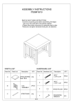
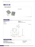
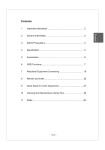
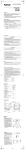
PDP SERVICE MANUAL
Model Number: PDP4249G
1. EMI BOARD Assembly/Disassembly Instruction
2. DC BOARD Assembly/Disassembly Instruction
3. AMPLIFIER BOARD Assembly/Disassembly Instruction
4. TUNER BOARD Assembly/Disassembly Instruction
5. VIDEO BOARD Assembly/Disassembly Instruction
6. POWER BOARD Assembly/Disassembly Instruction
7. KEY BOARD Assembly/Disassembly Instruction
1. EMI BOARD Assembly/Disassembly
(2)
(3)M5X8
(1)
STEP 1:
1.Turn off the main power switch on the back of the set and unplug
the power cord from the outlet.
cover.
3.Remove the 6pcs and 2pcs screws (M5X8 & M5X40) on each
corner of the back cover.
4.Remove the 2pcs screws (M3X8) of the back cover.
(4)
STEP 2:
BOARD.
2.Detach the back cover by unpluging the 2 connectors (2pin) from the
AMP BOARD.
(2)
(1)
STEP 3:
1.Unplug the power connector line (3pin) for the AC OUT.
2.Change the EMI BOARD by removing the 6pcs screws(M3X6).
(2)
(1)
Note:When installing the EMI Board, please notice that the AC
IN power connector line is connected on the right side, and the
AC OUT power connector line is connected on the left side. Misconnected will damage the DC Board.
2. DC BOARD Assembly/Disassembly
(2)
(3)M5X8
(1)
STEP 1:
1.Turn off the main power switch on the back of the set and unplug
the power cord from the outlet.
cover.
3.Remove the 6pcs and 2pcs screws (M5X8 & M5X40) on each
corner of the back cover.
4.Remove the 2pcs screws (M3X8) of the back cover.
(4)
STEP 2:
BOARD.
2.Detach the back cover by unpluging the 2 connectors (2pin) from the
AMP BOARD.
(2)
(1)
(2)
(1)
STEP 3:
1.Unplug the power connector(3pin) of the AC IN.
2.Unplug the power connector(5pin) of the DC OUT.
3.Change the DC BOARD by removing the 4pcs screws(M3X6).
(3)
Note:When installing the DC Board, please use extra caution
when plugging back the AC and DC power connector in
accordingly or it will cause the set to not be able to turn ON.
3. AMPLIFIER BOARD Assembly/Disassembly Instruction
(2)
(3)M5X8
(1)
STEP 1:
1.Turn off the main power switch on the back of the set and unplug
the power cord from the outlet.
cover.
3.Remove the 6pcs and 2pcs screws (M5X8 & M5X40) on each
corner of the back cover.
4.Remove the 2pcs screws (M3X8) of the back cover.
(4)
STEP 2:
BOARD.
2.Detach the back cover by unpluging the 2 connectors (2pin) from the
AMP BOARD.
(2)
(1)
(1)
STEP 3:
1.unplug the power connector (2pin) for the DC BOARD.
2.unplug the signal transmitting line (3pin) for the AMPLIFIER JACK
3.Change the AMPLIFIER BOARD by removing the 4pcs screws(M3
(2)
(3)
Note:Please install the connector in original position certainly.
4. TUNER BOARD Assembly/Disassembly Instruction
(2)
(3)M5X8
(1)
STEP 1:
1.Turn off the main power switch on the back of the set and unplug
the power cord from the outlet.
cover.
3.Remove the 6pcs and 2pcs screws (M5X8 & M5X40) on each
corner of the back cover.
4.Remove the 2pcs screws (M3X8) of the back cover.
(4)
STEP 2:
BOARD.
2.Detach the back cover by unpluging the 2 connectors (2pin) from the
AMP BOARD.
(2)
(1)
(1)
(4)
(2)
STEP 3:
1.unplug the signal transmitting connector (9pin) for the VIDEO BOA
2.unplug the power connector (4pin) for the VIDEO BOARD.
3.unplug the cable connector for the VIDEO BOARD.
4.Change the TUNER BOARD by removing the 4pcs of screws(M3x6
(3)
Note:Please install the connector in original position certainly.
5. VIDEO BOARD Assembly/Disassembly
(2
)
(3)M5X8
(1
)
(4
)
STEP 2:
BOARD.
2.Detach the back cover by unpluging the 2 connectors (2pin) from
the AMP BOARD.
(2)
(1)
(3)
(1)
(2)
(4)
(5)
(1)
STEP 1:
1.Turn off the main power switch on the back of the set and unplu
the power cord from the outlet.
cover.
3.Remove the 6pcs and 2pcs screws (M5X8 & M5X40) on each
corner of the back cover.
4.Remove the 2pcs screws (M3X8) of the back cover.
STEP 3:
3.Unplug the signal transmitting line for the LVDS PANEL(20PIN).
2.Unplug the signal transmitting line (12pin) for the KEY BOARD.
3.Unplug the power connector (6pin) for the DC BOARD.
4.Unplug the power connector (4pin) for the TUNER BOARD.
5.Unplug the signal transmitting line (9pin) for the TUNER BOARD.
6.Remove the 6pcs screws(M3X6) on each corner.
STEP 4:
1.Remove the 6pcs screws (M3X8) of the VIDEO PANEL.
2.Change the VIDEO BOARD by removing the 6pcs hexagona
screws(M3X6).
(2)
Note:(1)Please use extra caution when unplugging the 12PIN
and LVDS connector lines. Do not over pull it to avoid breaking
up the connector lines. Also, please make sure the PIN is
installed back in accordingly to aviode damaging its base.
6. POWER BOARD Assembly/Disassembly
(2)
(3)M5X8
(1)
STEP 1:
1.Turn off the main power switch on the back of the set and unplug the
power cord from the outlet.
2.Remove the 26pcs screws (M4X12) on each corner of the back cover.
3.Remove the 6pcs and 2pcs screws (M5X8 & M5X40) on each corner of
the back cover.
4.Remove the 2pcs screws (M3X8) of the back cover.
(4)
STEP 2:
1.unplug the AC IN power connector line (3pin) from the EMI BOARD.
2.Detach the back cover by unpluging the 2 connectors (2pin) from the
AMP BOARD.
(2)
(1)
(1)
(2)
(3)
STEP 3:
1.Unplug the power connector (8pin ) for the PANEL BOARD.
2.Unplug the power connector (4pin - yellow/black) for the PANEL BOAR
3.Unplug the power connector (4pin - red/black) for the PANEL BOARD.
4.Unplug the power connector (4pin - blue/black) for the PANEL BOARD.
(4)
(2)
1.Unplug the signal transmitting connector for the PANEL BUS at the butto
2.Change the POWER BOARD by removing the 8pcs screws(M3X6) on
each corner.
(1)
Note: Pleae make sure all the Power Connectors and the Bus signal
transmitting line are connected in accordingly.
7. KEY BOARD Assembly/Disassembly
(2)
(3)M5X8
(1)
STEP 1:
1.Turn off the main power switch on the back of the set and unplug the
power cord from the outlet.
2.Remove the 26pcs screws (M4X12) on each corner of the back cover.
3.Remove the 6pcs and 2pcs screws (M5X8 & M5X40) on each corner of
the back cover.
4.Remove the 2pcs screws (M3X8) of the back cover.
(4)
STEP 2:
1.unplug the AC IN power connector line (3pin) from the EMI BOARD.
2.Detach the back cover by unpluging the 2 connectors (2pin) from the
AMP BOARD.
(2)
(1)
(2)
(3)
(1)
STEP 3:
1.Unplug the signal transmitting line (3pin) for the SENSOR BOARD.
2.Unplug the signal transmitting line (12pin) for the VIDEO BOARD.
3.Change the KEY BOARD by removing the 4pcs screws(M3X6).
Note: Pleae make sure the 12PIN signal transmitting connector and the
SENSOR signal transmitting connector are connected in accordingly.