1
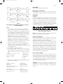
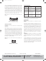
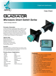
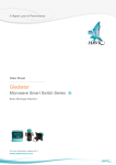
V-5
10/6/05
3:14 PM
Page 1
Bulletin V-5
Series 2900 Current to Pressure Transducer
Specifications - Installation and Operating Instructions
Ø3-1/2
(Ø88.9)
1
(25.4)
4 #10-32-UNF
TAPPED HOLES FOR
MOUNTING
1/2 NPT PORT FOR
CONDUIT PIPING
4-19/32
(116.6)
27/32
(21.3)
2-1/2
(63.5)
IN & OUT
PORTS 1/4-18 NPT
4 PLACES
2-3/16
(55.6)
57/64
(22.4)
49/64
(19.4)
2-5/64
(52.6)
1-1/2
(38.1)
33/64
(13.1)
The Series 2900 Current to Pressure Transducer delivers reli-
SPECIFICATIONS
able high performance for the toughest applications in the most
Service: Oil free, clean dry air filtered to 40 microns.
hazardous environments. Its NEMA 4X housing is designed and
Input Signal: 4-20 mA.
FM and CSA approved for both intrinsically safe and explosion-
Air Supply: Minimum: 5 psig (0.3 bar) above maximum output;
proof operation. This unit has advanced circuitry which includes
Maximum: 100 psig (6.9 bar).
electronic feedback control for superior vibration protection and
Output: 3 to 15 psig (0.2 to 1.0 bar), 6 to 30 psig (0.4 to 2.1 bar).
highly accurate output. The Series 2900 is not position sensitive
Accuracy: ±0.1% of span.
and the easily accessible zero and span adjustments make field
Hysteresis: ±0.1% of span.
calibration quick and easy. For ease of installation, this model has
Repeatability: ±0.1% of span.
input and output ports on both the front and back. It is also not
Deadband: 0.02% of span.
vibration sensitive, which makes the Series 2900 ideal for field
Power Requirement: Loop powered.
mounting on a valve. These features coupled with the unit’s com-
Temperature Limits: Operating: -40 to 160°F (-40 to 71°C);
pact size help make set-up and installation simple.
Storage: -40 to 200°F (-40 to 93°C).
Pressure Connections: 1/4˝ female NPT.
Electrical Connection: 1/2˝ female NPT.
Air Consumption: 0.05 scfm (0.02 l/s) at midrange typical.
Output Capacity: 4.5 scfm (2.1 l/s) at 25 psig (1.7 bar) supply;
12.0 scfm (5.7 l/s) at 100 psig (6.9 bar) supply.
Enclosure: Chromate-treated aluminum with epoxy paint.
Enclosure Rating: Weatherproof NEMA 4X (IP65), Explosionproof and intrinsically safe.
Weight: 1.8 lb (0.82 kg).
MODEL CHART
Model Number
2913-E
2916-E
Input
4-20 mA
4-20 mA
Output
3-15 psig (0.2-1.0 bar)
6-30 psig (0.4-2.1 bar)
W.E. ANDERSON DIV., DWYER INSTRUMENTS, INC.
P.O. BOX 358 • MICHIGAN CITY, INDIANA 46361 U.S.A.
Agency Approvals: CE, CSA, FM.
Phone: 219/879-8000
Fax: 219/872-9057
www.dwyer-inst.com
e-mail: [email protected]
V-5
10/6/05
3:14 PM
Page 2
page 2
INSTALLATION
Requirements
The Series 2900 transducer is suitable for installation in the following locations: Intrinsically safe operation in hazardous locations
outdoors (NEMA 4X, CSA.ENC.4 & IP65) and Explosion-proof
installation in hazardous locations outdoors (NEMA 4X,
CSA.ENC.4 & IP65).
DANGER: All wiring must be made to all local and national codes
appropriate to the area of installation.
Electrical Input: 4-20 mA DC current source. It is recommended
that shielded cable be used and that the shield be grounded to
unit and earth ground. See Figure 1 for location of ground screw.
Air Supply: Clean, dry, oil free instrument air filtered to 40 microns.
CAUTION: Use caution not to scar threads of fitting during installation as this can void integrity of the seal. Exhaust gas must be
vented to a safe area.
Figure 1
Zero Adjustment and Span Adjustment
Mounting
The Series 2900 has been designed to mount inline, to a standard
valve yoke with the A-180 valve mounting kit.
Factory Mutual Research (FM) Intrinsically Safe Ratings:
XP/I/1/BCD/T6 Ta = 70°C; DIP/II, III/1/EFG/T6 Ta = 70°C; IS/I, II,
III/1/CDEFG/T4 Ta = 70°C - 431-990-025 Entity; I/0/AEx ia IIB T4
Ta = 70°C - 431-990-025 Entity; NI/I/2/ABCD/T4 Ta = 70°C; Type
4X Entity Parameters: Ui (Vmax) = 30 V, li (lmax) = 125 mA, Pi =
0.70 W, Ci = 0 mH
Pneumatic Connections
Clean all pipe lines to remove dirt and scale prior to installation.
Supply air must be filtered to 40 microns and free of moisture and
lubricants.
Two 1/4˝ NPT ports are provided for supply air connections. Either
port may be used. The unused port must be plugged with the pipe
plug included with the unit.
Two 1/4˝ NPT ports are provided for pneumatic output connections. Either port may be used and one may be used for the
mounting of an output gage. If no gage is installed, the unused
port must be plugged with the pipe plug included with the unit.
Electrical Connections
The Series 2900 is supplied with a 1/2˝ NPT electrical conduit connection. A two position terminal block that is wire ready is supplied
for 22-12 AWG wire. Wire should be stripped approximately 1/4˝
before insertion. The terminals are labeled “+” and “–” on the terminal board (see Figure 1).
It is recommended that shielded cable be used and that the shield
be grounded at the unit (ground screw provided) and to earth
ground.
Note: Observe polarity. Reverse polarity will not damage the unit,
but unit will not operate.
CAUTION: Conduit should be connected to prevent condensation from collecting in the unit.
Equipment Ratings:
Explosion-proof for Class I Division 1, Groups B, C, and D. T6,
Dust Ignitionproof for Class I, Division 1, Groups E, F, and G, T6;
Intrinsically safe for Class I, II, and III, Division 1, Groups C, D, E,
F, and G, T4 hazardous (classified) locations and intrinsically safe
for Class I, Zone 0, Group IIB, T4 hazardous (classified) locations
and suitable for Class I, Groups A, B, C, D, T4, and Class II and
III, Division 2, Groups F and G, T6 hazardous (classified)
locations.
CSA Intrinsically Safe Ratings:
Class I Division 1, Groups B, C, and D; Class I, Division 2, Groups
A, B, C and D; Class II, Division 1, Groups E, F, and G; Class II and
III, Division 2, Groups F and G. Rated 7 to 30 VDC, 4 to 20 mA;
Enclosure Type 4X; Type 4X; Temperature Code T6 (CL I Div 1). T4
(CL I, Div 2), T6 (CL II, III, Div 2); Maximum Ambient 70°C.
Ex ia IIB (Class I, Zone 0, Group IIB)
Temperature Code T4; Maximum Ambient 70°C; Enclosure Type
4X; Intrinsically Safe with the following entity Parameters when
installed as per drawing 531-990-0246 Ui = 30 V, li = 125 mA, Pi
= 0.70 W, Ci = 0 μF, Li 0 mH.
Note: Cable capacitance and inductance must be considered
when connecting to pressure transducer.
V-5
10/6/05
3:14 PM
Page 3
page 3
ATEX (KEMA)
Explosion-proof/Intrinsically Safe Pending
EC Declaration of Conformity
RFI/EMI Effect: Less than .5% of span change in output pressure
per En 61000-4-3:1998, Amendment 1, Performance Criterion A.
Figure 2
Factory Mutual and Canadian Standards Association I.S.
Installation Drawing
Notes:
1. Control equipment connected to the Associated Apparatus
must not use or generate more than 250 Vrms or VDC.
2. The IS Barriers or Equipment (Associated Apparatus) must be
Factory Mutual Research Approved and the configuration of
Associated Apparatus may be installed within the Hazardous
(Classified) location for which it is approved. The Associated
Apparatus and hazardous location loop apparatus
manufacturer's control drawings must be followed when
installing this equipment. An AEx (ib) Associated Apparatus is
suitable only for connection to Class I, Zone I, Hazardous
(Classified) Locations and is not suitable for Class I, Zone 0, or
Class I, Division I Hazardous (Classified) Locations.
3. Installation should be in accordance with ANSI/ISA RP12.6
“Installation of Intrinsically Safe Systems for Hazardous
(Classified) Locations” and Article 500 of the National Electrical
Code (ANSI/NFPA 70).
4. All units suitable for Type 4X installations.
5. The Intrinsic Safety Entity concept allows the interconnection
of two FM Approved intrinsically safe devices with entity parameters not specifically examined in combination as a system
when:
Ui or Vmax > Uo or Voc or Vt > 7.2 Volts
Ii or Imax > Io or Isc or It
Ca or Co > Ci + Ccable
La or Lo > Li + Lcable
Pi > Po
Entity Parameters:
Ui (Vmax) = 30 V
Ii (Imax) = 125 mA
Pi = 0.70 watts
Ci = 0 uF
Li = mH
6. No revision to this drawing is permitted without prior Factory
Mutual Research Approval.
Hazardous Location Units:
FM & CSA
Explosion Proof:
Class I, Division 1, Groups B, C & D
Models 2913-E & 2916-E
Intrinsically Safe:
Class I, II & III, Division 1
Groups C, D, E, F & G
Models 2913-E & 2916-E
Dust Ignition Proof:
Class II & III, Division 1, Groups E, F & G
Models 2913-E & 2916-E
Suitable For:
Class I, II & III, Division 2,
Groups A, B, C, D, F & G
Models 2913-E & 2916-E
OPERATION
Calibration
All units are shipped from the factory calibrated, direct acting. If the
user requires a different mode of operation (i.e. reverse acting, split
range) it is necessary to reposition internal electrical dip switches
located on the circuit board (see Figure 1) as indicated in Figure 3.
Though the units are factory calibrated for direct acting operation,
it is suggested that the user check the calibration to ensure that
settings and operation match the application requirements.
Switch
ON
1
2
3
4
5
6
7
8
9
10
11
12
OFF
Figure 3
Direct Acting Switch Settings
Note: It is not necessary to remove the plastic cover of the unit for
calibration if the Direct Acting mode is desired.
Direct Acting Calibration
In direct acting operation the unit is calibrated so that minimum
input signal corresponds to minimum output pressure and increasing input signal results in increasing output pressure.
Apply the minimum input signal of the range being used (e.g. 4
mA). Observe the output pressure. If necessary, adjust the zero
screw until reaching minimum output pressure setting. Turn zero
screw clockwise to decrease and counter-clockwise to increase.
Apply the maximum input signal of the range being used (e.g. 20
mA). Observe the output pressure. If necessary, adjust the span
screw until reaching maximum output pressure setting. After setting the span it will be necessary to recheck the zero. Repeat steps
until both end points are at required values.
Reverse Acting Calibration
When calibrating to operate in the reverse acting mode the minimum input signal produces the maximum output pressure and
increasing the input signal results in decreasing the output pressure. Setting the unit to operate in the reverse acting mode is
accomplished by positioning internal electrical dip switches located on the circuit board (see Figure 1).
CAUTION: Do not touch any components on circuit board except
dip switches. Do not reverse the input leads. Damage may occur.
Transducer fails in direct mode regardless of operating mode
selected.
V-5
10/6/05
3:14 PM
Page 4
Access circuit board by first removing the die cast cover of the
unit. Then remove plastic cover by taking out two screws. Position
the dip switches as illustrated in Figure 4. Set the input signal to
the minimum value being used. Turn the zero screw to set the
maximum output pressure. Turn screw clockwise to decrease and
counter-clockwise to increase. Set the span by applying the maximum input signal. Turn the span screw to set the minimum output
pressure. Turn screw counter-clockwise to decrease and clockwise to increase. It may be necessary to repeat steps until both
end points are at desired values. Replace both covers.
Note: Switches not shown match Direct Acting Settings (see
Figure 3).
Switch
ON
3
4
5
6
7
TROUBLESHOOTING
Problem
Sluggish
performance
Look For
Solution
Blocked orifice
Clean external orifice
Output won’t go
above 0
No air input
Output stays
below 3 psi
with increase
of input
Unit will not go
full scale
with full-scale
input
Check Instrument
air supply
Input leads reversed
Bad electrical connection
Circuit board failure
Reverse input leads
Check input wiring
Factory Repair
Insufficient supply pressure Increase supply pressure
Check connections
Leak in connections
Factory Repair
Circuit board failure
Note: If problems are not solved by troubleshooting procedures,
contact an applications engineer for further assistance.
10
OFF
MAINTENANCE
Note: Under normal circumstances, no maintenance should be
required.
Figure 4
Reverse Acting Switch Settings
Split Range Calibration
CAUTION: Do not touch any components on circuit board except
dip switches.
When calibrated to operate in the split range mode a full input signal (i.e. 4-20 mA) will operate the unit at one half the normal output span (i.e. 3-9 psig, 9-15 psig). Setting the unit to operate in the
split range mode is accomplished by positioning internal electrical
dip switches. Access circuit board by first removing the die cast
cover of the unit. Then remove plastic cover by taking out two
screws. Position switches as illustrated in Figure 5. Replace both
covers. After replacing covers, refer to the appropriate calibration
procedure (Direct Acting or Reverse Acting) to get to desired output range (i.e. 3-9 psig, 9-15 psig).
Note: Switches not shown match Direct Acting Settings (see
Figure 3).
Switch
ON
1
2
OFF
Figure 5
Split Range Switch Settings
©Copyright 2005 Dwyer Instruments, Inc.
Failures due to instrument supply air contamination are not covered by warranty. Use of oil and/or water saturated instrument air
can cause erratic operation. Poor quality instrument air can result
in unit failure. It is recommended that a filter regulator (such as
Dwyer Series AFR) be placed upstream of each unit where oil
and/or water laden instrument air is suspected. If clean, dry air is
not used the orifice can become blocked. To clean, first turn off
supply air, then remove the screw located on the side of the unit
above the “out” port. Unplug the orifice using a wire that has a
smaller diameter than 0.012˝ (0.30 mm). Replace screw tightly into
unit.
WARNING: These products are intended for use in industrial
compressed-air systems only. Do not use these products where
pressures and temperatures can exceed those listed under specifications.
The Series 2900 Current to Pressure Transducers are not field
repairable and should be returned if repair is needed (field repair
should not be attempted and may void warranty). Be sure to
include a brief description of the problem plus any relevant application notes. Contact customer service to receive a return goods
authorization number before shipping.
Printed in U.S.A. 10/05
W.E. ANDERSON DIV., DWYER INSTRUMENTS, INC.
P.O. BOX 358 • MICHIGAN CITY, INDIANA 46361 U.S.A.
Phone: 219/879-8000
Fax: 219/872-9057
FR# R2-443363-00
www.dwyer-inst.com
e-mail: [email protected]