1
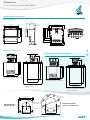
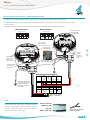
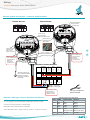
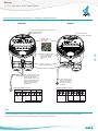
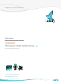
Overview Gladiator Microwave Smart Switch Series A Higher Level of Performance Data Sheet Gladiator Microwave Smart Switch Series Beam Blockage Detection For more information, please visit > www.hawkmeasure.com > Overview Gladiator Microwave Smart Switch Series Overview Principle of Operation A beam of microwave energy passes from a sender to a separate receiver in bursts approximately 200 times per second. If the path between the sender and receiver is blocked by any object or material which absorbs or reflects microwave energy, the receiver will not be able to detect the signal. The presence or absence of the signal at the receiver is used to switch a relay for indication or control purposes. Typical Uses Primary Areas of Application • Blocked chute detection • Asphalt • Packaging • Stacker / reclaimer protection • Brewing • Paint • Shiploader protection • Cement • Paper • Nucleonic switch replacement • Chemical • Pharmaceutical • High level alarm / Low level alarm • Dairy • Plastics • Truck / machine detection. • Edible oil • Power Generation • Fertilizer • Refining • Food & Beverage • Semiconductor • Glass • Sugar • Mining & Metals • Textile • Oil & Gas • Water & Wastewater. Function The Gladiator Microwave Smart Switch can be used for blockage detection, barrier detection, machine detection or protection and point level measurement, and detection of objects or material between two points. Note: For wet, dusty environments where build up issues of wet high dielectric material is prevalent Microwave technology will have performance problems. HAWK recommends the Gladiator Acoustic Switch for these applications. Features • LCD setup / diagnostics on remote amplifier • Ranges up to 200 meters (656 ft) • Simple ‘1-minute’ setup • Remote sensor or Smart Integral ‘all in one’ types • Relay outputs: Smart Integral (1) Remote (2) • Remote test function 2 • Adjustable ON and OFF delays (0-20 sec) • Remote 3G connection option • Remote amplifier to sensor separation up to 500 meters (1640 ft) • Bright visual status indication on sensors • Independent housing alignment after mounting sensor. > < Overview Typical Applications Gladiator Microwave Smart Switch Series Overview Cement Plants / Powders Coal Fired Power Station, Bulk Material Handling Solid Level - Cyclone Bin High / Low Level High / Low blocked chute detection For dual receiver wiring see user manual. Receiver Sender High CAL Receiver RUN Sender > Low < CAL RUN CAL RUN “Blocked Chute” Mount Microwave under pulley or out of main system flow 3 Overview Dimensions Gladiator Microwave Smart Switch Series Overview Remote Microwave System 111.5 mm (4.4”) 30.7 mm (1.2”) 78 mm (3.1”) 14 mm (0.6”) 192.5 mm (7.6”) 147 mm (5.8”) 131.5 mm (5.2”) 141.5 mm (5.6”) 167.5 mm (6.6”) 190 mm (7.5”) 107 mm (4.2”) 108 mm (4.3”) 190 mm (7.5”) 174 mm (6.9”) 16.2 20.2 30.0 192.5 mm (7.6”) 7.5 mm (0.3”) Remote Amplifier 33.0 182.5 mm (7.2”) 29.0 29.0 33.0 147 mm (5.8”) 50 mm (2”) 74 mm (2.9”) 158 mm (6.2”) 182.5 mm (7.2”) 4 mm (0.2”) > Remote Sender / Receiver Smart Integral Microwave System • Standard Sender / Receiver 12 mm (0.5”) 250 mm (9.8”) Ø88 mm (3.5”) Ø160 mm (6.3”) 90 mm (3.5”) 50 mm (2”) 129.5 mm (5.1”) 135.5 mm (5.3”) 250 mm (9.8”) 129.5 mm (5.1”) 135.5 mm (5.3”) 2 mm (0.078”) 10 mm (0.4”) 50 mm (2”) 90 mm (3.5”) 90 mm (3.5”) 50 mm (2”) 10 mm (0.4”) 90 mm (3.5”) 50 mm (2”) 2 mm (0.078”) < Ø85 mm (3.3”) Ø85 mm (3.3”) 12 mm (0.5”) Ø85 mm (3.3”) Ø85 mm (3.3”) Ø88 mm (3.5”) Ø160 mm (6.3”) • Standard Sender / Receiver Ø165 mm (6.5”) Ø277 mm (10.9”) • High Power Sender, Receiver or SRS Receiver Ø165 mm (6.5”) Ø277 mm (10.9”) • High Power Sender, Receiver or SRS Receiver 8xØ22 mm Holes THRU 160 mm (6.3”) 135 mm (5.3”) 160 mm (6.3”) Standard Sender / Receiver Flange Alignment marks .3”) m(9 8m Ø23 4x10 mm holes Ø88.5 mm (3.5”) Ø165 mm (6.3”) Ø277 mm (10.9”) 4 High Power Sender / Receiver or SRS Flange Overview Wiring Gladiator Microwave Smart Switch Series Overview Remote System Connection - HAWK Supplied Cable • The black wire of HAWK supplied cable comes with one end GND and the other GND / SHLD together. • The GND / SHLD end is a larger cable which has been heat shrunk. The GND only end is the same size as the other coloured cables. • The GND / SHLD end must be connected to the amplifier and the GND end to the sender / receiver. Remote Receiver Remote Sender Terminals 1, 2, 3, 9, 10 not used 9. 10. Red Transmitter enabled LED 8. BLACK 7. RED 5. 6. 4. BROWN 3. 2. 1. 9. 10. 8. BLACK 7. RED 5. WHITE 6. BLUE 4. BROWN 3. 2. 1. Green Power ON LED TERMINAL LAYOUT TERMINAL LAYOUT INT 1 1 Green Power/ Signal strength/ alignment indicator LED Signal 2 3 4 5 6 2 3 MICROWAVE SENDER 3 PRESS TO TEST PWR TX 4 5 6 7 8 9 10 Remove Plug-In terminal block for easier wiring Status 1 2 Terminals 1, 2, 3, 5, 6, 9, 10 not used 7 8 > Add wire between terminal 8 and ground screw 9 10 Signal strength/ alignment test point for volt meter connection Hole for securing of optional identification tag M4 grounding screw Add wire between terminal 8 and ground screw ** Gladiator Remote Amplifier 8 9 4-20mA (N/A) SENSOR NO 7 26 27 28 29 30 10 11 12 13 14 15 – + L1 6 COM 5 NC 4 25 N 3 NO 2 + – COM 24 NC TEST IN 23 RELAY 2 A MASTER OUT 22 B 21 BROWN SLAVE IN 20 WHITE BROWN 19 BLUE BLACK 18 BLACK 1 17 RED 16 Is **Ground the housing to vessel, if vessel is metallic. Ground the housing to plant ground, if vessel is non-metallic. RELAY 1 RED MIC-SENDER DC-In AC-In* COMMS Relay 1 - Output Relay Relay 2 - FailSafe Relay Note: AC power terminals may only be used when universal AC power supply option has been selected - see part numbers - AC terminals have no function in products without universal AC power option. 5 Sender / Receiver (GND only end) Amplifier (GND / SHLD end) Use long nose pliers to extract terminals < Overview Wiring Gladiator Microwave Smart Switch Series Overview Remote System Connection - Customer Supplied Cable Remote Receiver Remote Sender Red Transmitter enabled LED 9. INT 1 10. 8. BLACK 7. RED 5. 6. 3. 4. BROWN 2. 1. 9. 10. 8. BLACK 7. RED 5. WHITE 6. BLUE 3. 4. BROWN 2. TERMINAL LAYOUT 1. Green Power ON LED TERMINAL LAYOUT 1 Green Power/ Signal strength/ alignment indicator LED Signal 3 4 5 6 2 3 4 5 6 7 8 9 10 Remove Plug-In terminal block for easier wiring. Status 2 MICROWAVE SENDER 3 PRESS TO TEST PWR TX Terminals 1, 2, 3, 5, 6, 9, 10 not used Terminals 1, 2, 3, 9, 10 not used 1 2 7 8 9 10 Signal strength/ alignment test point for volt meter connection > Hole for securing of optional identification tag SHIELD wire is NOT CONNECTED at terminal block SHIELD is connected to grounding screw M4 grounding screw SHIELD wire is NOT CONNECTED at terminal block SHIELD is connected to grounding screw ** Gladiator Remote Amplifier 8 9 4-20mA (N/A) SENSOR NO 7 COM 6 26 27 28 29 30 10 11 12 13 14 15 – + L1 5 NC 4 25 N 3 NO 2 + – COM 24 NC TEST IN 23 RELAY 2 A MASTER OUT 22 B 21 BROWN SLAVE IN 20 WHITE BROWN 19 BLUE BLACK 18 BLACK 1 17 RED 16 Is **Ground the housing to vessel, if vessel is metallic. Ground the housing to plant ground, if vessel is non-metallic. RELAY 1 RED MIC-SENDER DC-In AC-In* COMMS Relay 1 - Output Relay Relay 2 - FailSafe Relay Connect BOTH GND AND SHIELD to ‘black’ terminal at Amplifier end only Alternate cable type between Amplifier and Sensors • 6 or 8 conductor (5 used) shielded twisted pair instrument cable. • Conductor size dependent on cable length. • BELDEN 3120A, DEKORON or equivalent. • Max: BELDEN 3120A = 500m (1640 ft). 3 pairs, 1 conductor not used. 6 Use long nose pliers to extract terminals Alternate Cable Colour Equivalents Pairs HAWK Belden 3120A Dekoron Pair 1 Red Black Red Black White 1 Black 1 Pair 2 White Blue Yellow Green White 2 Black 2 Pair 3 Brown --- Brown White (not used) White 3 Black 3 (not used) Pair 4 not used not used not used < Overview Wiring Gladiator Microwave Smart Switch Series Overview Smart Integral System Connection - Customer Supplied Cable Receiver Sender Green Power/Signal strength/alignment indicator LED Blue Calibration/Error LED Green Power ON LED Y HI FSH CAL EN S 1 2 3 4 5 6 7 8 Red Transmitter enabled LED Remove Plug-In terminal block for easier wiring. TEST DELAY SITIVIT Red Relay Status LED INT 1 9 10 1 2 2 3 MICROWAVE SENDER 3 PRESS TO TEST PWR TX 4 5 6 7 8 9 10 The AC earth/ground cable must be connected to the ground screw inside the housing when using AC power. > < Hole for securing of optional identification tag M4 grounding screw If only one cable is used for both power and output signal, then the second entry port must be plugged or blinded. Every Smart receiver is supplied with two M20 glands (or 3/4”NPT adaptors) mounted on the unit and one blind plug loose. SENDER TERMINAL LAYOUT 12-30VDC 80-260VAC - N L1 8. 9. 10. AC-IN + 6. 5. 4. 3. 2. 1. 8. L1 7. 10. + 6. RS 485 N B - DC-IN AC-IN 9. A DC-IN 5. 4. Test NO 3. 1. 2. COM RELAY COMMS 7. RECEIVER TERMINAL LAYOUT NC ** **Ground the housing to vessel, if vessel is metallic. Ground the housing to plant ground, if vessel is non-metallic. 12-30VDC 80-260VAC Terminals 1, 2, 3, 4, 5, 6 not used Note: AC power terminals may only be used when universal AC power supply option has been selected - see part numbers AC terminals have no function in products without universal AC power option. 7 Overview Wiring Gladiator Microwave Smart Switch Series Overview Cross-Talk Prevention - Sequencing two remote systems To prevent possible interference between two remote beam blockage detection systems mounted in close proximity, one system must be selected as a ‘Master’ and the other as a ‘Slave’. The Operation Mode selection can be found in the advanced menu of the remote amplifier for each system. Operation Mode has 3 selections: 1. Remote - normal unsequenced (single system) operation. 2. Master - controlling system in a sequenced group of two units. 3. Slave - controlled system in a sequenced group of two units. Additional wiring must be installed between the two amplifiers as shown below. A connection must be made between the ‘Master Out’ terminal of the amplifier selected to operate as the Master and ‘Slave In’ terminal of the unit selected to operate as the Slave. The cable shield and / or a second connection must link the DC-IN ‘-’ terminals of the two units. • Smart integral systems are not intended to be sequenced. • If systems are to be installed in close proximity to one another, remote types should be used to allow sequencing. • Sequencing of more than 2 systems near one another must be done using a GMSEQ sequencing unit connected to all systems as described in the manual. > < Sender 1 Receiver 2 Ground * Software selected 8 5 6 7 8 9 4-20mA (N/A) SENSOR NO 4 COM 3 24 25 26 27 28 29 30 10 11 12 13 14 15 – + L1 2 + – NC 23 N 22 NO AC-In* 21 COM DC-In COMMS 20 TEST IN 1 MASTER OUT 15 19 DC-In AC-In* B 14 SLAVE IN 13 18 BROWN 12 BROWN 11 – + 17 WHITE 10 BLACK 16 Is 30 L1 29 B 28 NC SENSOR 27 RELAY 2 A 4-20mA (N/A) 26 BLUE 9 25 RELAY 1 RED 8 NO 7 COM 6 NC 5 24 N 4 NO 3 COM 2 + – TEST IN 23 NC MASTER OUT 22 MIC-SENDER RELAY 2 A SLAVE IN 21 BROWN BROWN 20 WHITE BLACK 19 BLUE 18 RED Is 1 17 BLACK 16 RELAY 1 RED MIC-SENDER GLADIATOR MICROWAVE REMOTE AMPLIFIER SLAVE RED GLADIATOR MICROWAVE REMOTE AMPLIFIER MASTER BLACK Receiver 1 Sender 2 COMMS Overview / Installation Mounting Gladiator Microwave Smart Switch Series Overview Correct Mounting Angle Align Sender and Receiver Correct Elevation Rotate so that Visual Alignment Guide is in the same position on both sender and receiver. Maximum Signal Strength to Receiver is indicated by maximum brightness of Green LED on Receiver. Sending Unit Receiving Unit Microwave Beam Incorrect Elevation Sending Unit Receiving Unit > < Installation with Adjustable Mounting Blocked Chute Mounting MAIN PRODUCT FLOW Receiving Unit Sending Unit Position blocked chute detectors to one side of main product flow Mounting with Windowed Weldments Flow/No Flow Metal Bin/Chute Walls MAIN PRODUCT 4” UHMW Windowed Weldment FLOW Sender Receiver Fabricated Bracket 9 Position and aim fabricated brackets to separate structure flowAttach sensors Flow/No Flow Switch if bin/chute walls are subject to high vibration toward main Housing can be rotated within 200º after the mounting thread is tightened, to allow cable entries to face downwards or allow optimal cable clearance. Overview Part Numbering Gladiator Microwave Smart Switch Series Overview Remote Version Remote Amplifier GSA Gladiator Amplifier (compatible with all Gladiator products), Modbus Housing S Polycarbonate Power Supply B 12-30 VDC C 30-48VDC and 48-90VAC U 12-30VDC and 90-260VAC Output Options S Switch. 1 level relay, 1 failsafe relay Approval A22 ATEX Grp II Cat 3 GD T85°C IP67 Tamb -40°C to 70°C GSA S U S Remote Sender / Receiver GMSB GMRR GMSHB GMRRH GMRRS Gladiator Microwave Sender Gladiator Microwave Remote Receiver Gladiator Microwave Sender High Power Gladiator Microwave Remote Receiver High Power Gladiator Microwave Remote Receiver with Signal Recognition Stability Frequency 1 10 GHz Transducer Facing Material Selection 0 UHMW Polyethylene 1 PTFE Teflon W Wave guide connector (consult factory) Transducer Housing Material 1 Aluminium / Mild Steel 2 Stainless Steel for GMSB / GMRR 3 Stainless Steel for GMSHB / GMRRH or GMRRS Output Option X Not Required - Outputs generated from GSA amplifier Approval Standard X Not Required A 22 ATEX Grp II Cat 3 GD T85°C IP67 Tamb -40°C to 70°C GMSB 1 0 1 X X Connection Cable CA-GMR Pre-cut cable for remote sender or receiver 10 20 30 50 100 CA-GMR 10 10 10m cable 20m cable 30m cable 50m cable 100m cable > < Overview Part Numbering Gladiator Microwave Smart Switch Series Overview Smart Integral Version GMS Gladiator Microwave Sender GMSH Gladiator Microwave Sender High Power GMSR Gladiator Microwave Smart (Integral) Receiver GMSRH Gladiator Microwave Smart (Integral) Receiver High Power GMSRS Gladiator Microwave Smart (Integral) Receiver with Signal Recognition Stability Power Supply B 12-30 VDC C 30-48VDC and 48-90VAC U 12-30VDC and 90-260VAC Frequency 1 10 GHz Transducer Facing Material Selection 0 UHMW Polyethylene 1 PTFE Teflon W Wave guide connector (consult factory) Transducer Housing Material 1 Aluminium / Mild Steel (Standard) 2 Full stainless steel GMS or GMSR 3 Full stainless steel GMSH / GMSRH or GMSRS Output Option X Not Required for Sender units S Switch, 1 output relay with Modbus for Receiver units Approval Standard X Not Required A22 ATEX Grp II Cat 3 GD T85°C IP67 Tamb -40°C to 70°C GMSR X B 1 0 1 S MA Mounting Accessory Type 0 1 3 4 5 6 7 8 9 10 11 12 13 14 15 16 17 18 19 20 21 22 25 MA4 11 3” Weldment, each 2” Glass window each 3” UHMW Windows & Weldment each 4” UHMW Windows & Weldment each 6” UHMW Windows & Weldment each 3” PTFE Windows & Weldment each 4” PTFE Windows & Weldment each 6” PTFE Windows & Weldment each 9’ x 4,5” Fire brick each 6” x 4” ceramic brick each Shock insulation mounts pack of 4 Adjustable mounting UHMW windows each Adjustable mounting PTFE windows each Remote wave guide Assembly Flanged extension pipe (for long range applications) 3” Ceramic window & Weldment each 4” Ceramic window & 4” Weldment each 4” Microwave Weldment only each 3” Stainless steel Weldment only for UHMW each 4” UHMW Windows only each 3” UHMW Windows only each 4” Stainless steel Weldment only for UHMW each Stainless Steel Flanged extension pipe (for long range applications) GMSEQ Gladiator Microwave Sequencer Power Supply B 12-30VDC C 30-48VDC and 48-90VAC U 12-30VDC and 90-260VAC GMSEQ U HAWKLink Modem Model HL HAWKLink Type R Remote stand alone system c/w antenna Power Supply B 12-30VDC C 30-48VDC and 48-90VAC U 12-30VDC and 90-260VAC Network Type G3 3G Simcard S3 Australian Simcard expires after 3 month S12 Australian Simcard expires after 12 month X Not Required (customer supplied data enabled simcard) HL R U G3 S3 > < Overview Specifications Gladiator Microwave Smart Switch Series Overview Operating Voltage Alternate cable type between Amplifier and Sensors • Smart 12-30Vdc / Remote 12-30Vdc (residual ripple no greater than 100mV) • Smart 80-260Vac / Remote 90-260Vac 50 / 60Hz. • 6 or 8 conductor (5 used) shielded twisted pair instrument cable • Conductor size dependent on cable length • BELDEN 3120A, DEKORON or equivalent • Max: BELDEN 3120A = 500m (1640 ft). 3 pairs, 1 conductor not used • Max: DEKORON IED183AA004 = 350m (1150 ft). 4 pairs, 3 conductors not used. Power Consumption • <0.8W @ 24Vdc • <5VA @ 240Vac • <3VA @ 115Vac Maximum Operating Pressure • 2 BAR Communications Display (Remote version only) • GosHawk, Modbus • Multidrop mode can address 1-250 units over 4 wires. • 2 line x 12 character alphanumeric LCD • Backlight standard. Relay Output: (1) SMART (2) Remote • Form ‘C’ (SPDT) contacts, rated 5A at 240Vac resistive • Remote fail-safe test facility for one relay. Operating Temperature • Remote electronics -40°C (-40°F) to 80°C (176°F) • Smart Units -30°C (-20°F) to 65°C (150°F)* • Remote Sensors -30°C (-20°F) to 65°C (150°F)*. *For higher temperature applications, remote mounting with refractory windows is necessary. Memory - Remote • Non-Volatile (No backup battery required) • >10 years data retention. Enclosure Sealing • Smart Sensors IP67 • Remote Electronics IP65 (Nema 4x) • Remote Sensors IP67. < Transmitted Signal • Frequency: 10.525GHz • Average Power Density: 20µW/cm² typical • Linearly Polarised Field • Beam angle (3db) approximately 30º (10GHz). Fail-Safe • Selectable - presence or absence of material • High level fail-safe: relay is activated when material is present • Low level fail-safe: relay is activated when no material is present. Range • Maximum range under ideal conditions: 200m (656ft) • Minimum range under ideal conditions: 10cm (4 inches). Remote Sensors: 1 x M20 Gland / 3/4” NPTF threaded adaptor Remote Amplifier: 4 x 20mm (0.8”), 1 x 16mm (0.6”) knock outs Smart Integral Units: 2 x M20 Glands / 3/4” NPTF threaded adaptors. Mounting • 3” male NPT thread or four 10mm (0.4”) holes in flange on standard units or 6” ANSI flange on high power / SRS units • 3” Weldments for standard mounting on vessel wall • Flange for mounting separate from vessel wall - isolation shock mounts are available • 4” or 6” Weldments with PTFE (teflon) or UHMW windows • Ceramic window assemblies • Firebrick window assemblies available on custom basis • 2” NPT sight glass window • Waveguides - custom assemblies available for high temperature and limited access applications. Remote Test Input Note: Minimum ranges are dependent on application conductivity. Press to test (used to check for malfunction of unit from remote position, PLC, SCADA etc). Sender / Receiver to Amplifier Separation Weight • Up to 500m (1640ft) using specified extension cable. • GSA 1kg • GMS 5kg • GMR 5kg Hawk Measurement Systems Hawk Measurement (Head Office) 7 River Street Middleton, MA 01949, USA 15 - 17 Maurice Court Nunawading VIC 3131, AUSTRALIA Phone: +61 3 9873 4750 Fax: +61 3 9873 4538 [email protected] Phone: +1 888 HAWKLEVEL (1-888-429-5538) Phone: +1 978 304 3000 Fax: +1 978 304 1462 [email protected] For more information and global representatives: www.hawkmeasure.com Additional product warranty and application guarantees upon request. Technical data subject to change without notice. Represented by: DOC-MIC_SWITCH-DAT v1 • Rated from emitter to receiver at approximately 20µW/cm² • Complies with FCC Title Rules Part 15 (Beam Blockage) • Caution sign posting not required. All company or product names are registered trademarks or trademarks of their respective owners. Cable Entries Power Density