1
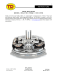
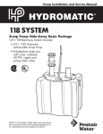
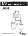
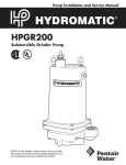
151 INDUSTRIAL DRIVE
ASHLAND, MISSISSIPPI 38603
http://www.tciauto.com
TELEPHONE: 662-224-8972
FAX LINE: 662-224-8255
E-MAIL: [email protected]
TCI® 861710 BURNOUT KIT
This TCI Kit Contains:
Qty. Description
Qty.
Description
1
2
1
1
2
1
1
2
6 ft.
6 ft.
25 ft.
2
Burnout Module
LED Lights
Red Wire
Black Wire
Black Wire
LED mount screws
& washers
Burnout Solenoid
Mounting Screws
Micro Switch
Wire Connector Kit
Mounting Brackets
Fuse Holder
ATTENTION!! Disconnect Battery before beginning!!!
Step 1 Select a mounting location that will position the
solenoid between the proportional valve and the front wheel
cylinder. (Can be installed for rear system if required. Just
connect to rear brake system.) Kit contains two (2) 1/4”x13/4” self-tapping screws. Use 3/8” socket to mount solenoid
in place.
Step 2 Before mounting solenoid; note that the solenoid has
two (2) openings. The brake lines are connected to these
openings. There are two (2) common size brake lines
available. TCI’s solenoid will work with either size. But you
will need to purchase the proper bushing adapter. The
thread size in the TCI solenoid is 1/8” straight pipe thread.
Purchase either an adapter that goes from 1/8” to 1/4”
inverted flair or 1/8” to 3/16” inverted flair. When using
the bushing adapters you may use TEFLON® tape on the
adapter threads but do not cover the first two (2) threads.
Use of an excessive amount of TEFLON® sealing tape can
cause contamination of brake system. You must obtain a
pair of brake line fittings to join the brake line to the solenoid.
The brake line fittings will seal the system and keep from
leaking fluid pressure.
Step 3 Mount solenoid securely.
Step 4 Next, connect brake lines. The opening that is
marked “Master” must be connected to the proportional
valve and the opening that is marked “Brake” must be
connected to the front wheel cylinder. Use only DOT grade
or better brake lines.
Step 5 Bleed brake system. After the brake lines are
installed, the system must be air bled to release any air
trapped in the system. Consult service manual for your
vehicle for special procedures. Refill master cylinder to
proper level using approved DOT brake fluid.
Step 6 Wiring the solenoid, LED’s and LED Module. The
solenoid has two (2) wires: one (1) ground wire and one (1)
“hot” wire. Proper installation is required. Make sure that the
ground wire (black) is connected to a good clean contact
area. When connecting wires, use barrel connectors or other
electrical connectors. If additional wire is required, use only
the same gauge or larger.
Step 7 Refer to Figure 1 for correct wiring of the Switch,
LED’s, LED Module and fuse.
Step 8 Mounting micro switch. The bracket provided can be
easily mounted in a variety of locations. The switch must be
mounting for easy operation. We suggest mounting close to
the steering wheel or on the shifter. After you have selected
where the switch will be mounted, measure length of wire
needed to make the connection. Make sure that the
terminals of the micro switch are connected to the wires
properly. Mount the Burnout module under the dash, then
using the included mounting brackets and the 10X24 screws
and washers; mount the LED to the bracket as shown in
Figure 2. Mount brackets to wheel wells or in an
inconspicuous place out of the way but where it points
toward the back of the rear tires and/or vehicle. Secure all
loose wires to avoid contact with any moving object.
Step 9 Test system: Reconnect battery. Jack vehicle up until
the wheels are off the floor. Using proper weight jack stands
secure the vehicle on the stands. Turn ignition on. Next,
have someone turn the electrical system on, push on the
brake pedal, press the micro switch button down and hold,
then release the brake pedal. If wired properly this will
engage the front wheel cylinder and keep the front wheels
from turning and cause the LED’s to function. Next, try to
turn the front tires. When the micro switch is depressed, you
should not be able to turn the tires. Only when the micro
switch button is release, will you be able to turn the tires.
(over)
Figure 1
Figure 2
10/2010SM