1
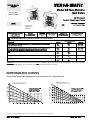
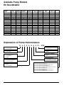
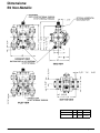
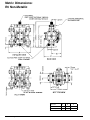
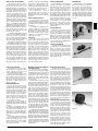
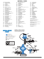
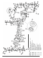
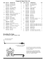
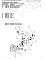
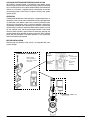
SERVICE & OPERATING MANUAL
®
Model E6 Non-Metallic
Ball Valve
U.S. Patent #
5,996,627 and
6,241,487
CE
Table of Contents
Engineering Data and Temperature Limitations.................... 1
Performance Curves ............................................................. 1
Explanation of Pump Nomenclature ..................................... 2
Dimensions .......................................................................... 3
Metric Dimensions ................................................................ 4
Principle of Pump Operation ................................................ 5
Check Valve Servicing ......................................................... 5
Diaphragm Servicing ............................................................ 5
Troubleshooting .................................................................... 6
Warranty ............................................................................... 6
Recycling ............................................................................. 6
Important Safety Information ................................................. 6
Material Codes ..................................................................... 7
Installation Guide ................................................................. 7
Composite Repair Parts Drawing ......................................... 8
Available Service and Conversion Kits ................................ 8
Composite Repair Parts List ................................................. 9
Grounding the Pump ............................................................ 9
Solenoid Shifted Option Drawing ....................................... 10
Solenoid Shifted Air Valve Parts List .................................. 10
Solenoid Shifted Options.................................................... 11
Solenoid Connector Drawing ............................................. 11
Versa-Matic®, IDEX AODD, Inc. • A Unit of IDEX Corporation • 800 North Main Street, P.O. Box 1568 • Mansfield, OH 44901-1568 USA
Tel: 419-526-7296 • Fax: 419-526-7289 • www.versamatic.com
520-361-000 04/04a
®
Model E6 Non-Metallic
Ball Valve
Quality System
ISO9001 Certified
U.S. Patent #
5,996,627 and
6,241,487
CAUTION! Operating temperature limitations are as follows:
CAUTION: Plastic pumps and components are not UV stabilized. Ultraviolet radiation can damage these parts and negatively
affect material properties. Do not expose to UV light for extended periods of time.
PERFORMANCE CURVES
(Versa-Matic® pumps
are designed to be powered only by compressed air)
Maximum air consumption for any point on
the performance curve is 3 LPS.
Contact the factory for exact air consumption.
TOTAL HEAD IN PSI
TOTAL HEAD IN Kg/cm2
Maximum air consumption for any point on
the performance curve is 6 SCFM.
Contact the factory for exact air consumption.
CAPACITY IN US GALLONS PER MINUTE
Santoprene® is a registered tradename of Monsanto Corp. Versa-Matic® is a registered tradenames of Versa-Matic, Inc.
CAPACITY IN LITERS PER MINUTE
Available Pump Models
E6 Non-Metallic
MODEL
TYPE
Pump
Size
Wetted
Material
Non-Wetted
Material
Diaphragm
Material
Diaphragm
Series
Valve Ball
Material
Wetted
Seals
Type of
Construction
Options
E6PP6X650
6
P
P
6
X
6
5
0
–
E6PP6X550
E6PP5B550
E6KP6X650
E6KP6X550
E6KP5B550
E6GG6X650
E6GG6X550
E6GG5B550
E6PP6X650-E0
E6PP6X650-E1
E6PP6X650-E2
E6PP6X650-E3
E6PP6X650-E4
E6PP6X650-E5
E6PP6X650-E6
E6PP6X650-E7
6
6
6
6
6
6
6
6
6
6
6
6
6
6
6
6
P
P
K
K
K
G
G
G
P
P
P
P
P
P
P
P
P
P
P
P
P
G
G
G
P
P
P
P
P
P
P
P
6
5
6
6
5
6
6
5
6
6
6
6
6
6
6
6
X
B
X
X
B
X
X
B
X
X
X
X
X
X
X
X
5
5
6
5
5
6
5
5
6
6
6
6
6
6
6
6
5
5
5
5
5
5
5
5
5
5
5
5
5
5
5
5
0
0
0
0
0
0
0
0
0
0
0
0
0
0
0
0
–
–
–
–
–
–
–
–
E0
E1
E2
E3
E4
E5
E6
E7
Explanation of Pump Nomenclature:
E 6 P P 6 X 6 5 0 – XXX
PUMP MODEL
E = Elima-Matic®
TYPE OF CONSTRUCTION
0 = Clamped Style
PUMP SIZE
6 = ¼" Pipe Size
WETTED SEALS
5 = PTFE
WETTED MATERIAL
G = Groundable Acetal
P = Polypropylene
K = PVDF
VALVE BALL MATERIAL
5 = PTFE
6 = XL
NON-WETTED MATERIAL
P = Polypropylene/Delrin/SS
G = Conductive Acetal
DIAPHRAGM MATERIAL
5 = PTFE
6 = XL (Santoprene)
520-361-000 Page 2
DIAPHRAGM SERIES
X = Thermo-Matic™. bead style
B = Versa-Tuff, 1 piece PTFE
OPTIONS
E0 = Solenoid Kit w/24 VDC Coil
E1 = Solenoid Kit w/24 VDC Explosion Proof Coil
E2 = Solenoid Kit w/24 VAC/12VDC Coil
E3 = Solenoid Kit w/24 VAC/12VDC Explosion Proof Coil
E4 = Solenoid Kit w/110VAC Coil
E5 = Solenoid Kit w/110VAC Explosion Proof Coil
E6 = Solenoid Kit w/220VAC Coil
E7 = Solenoid Kit w/220VAC Explosion Proof Coil
Model E6 Non-Metallic
Dimensions:
E6 Non-Metallic
Model E6 Non-Metallic 1
Dimension
A
B
C
Standard
7"
3.1/8"
5.1/2"
Pulse Output Kit
9"
3.9/16"
5.15/16"
520-361-000 Page 12
3
Metric Dimensions:
E6 Non-Metallic
Dimension
520-361-000 Page 4
A
B
C
Standard
178
79
140
Pulse Output Kit
229
90
151
Model E6 Non-Metallic
PRINCIPLE OF PUMP OPERATION
This ball type check valve pump is
powered by compressed air and is a 1:1
ratio design. The inner side of one
diaphragm chamber is alternately pressurized while simultaneously exhausting
the other inner chamber. This causes the
diaphragms, which are connected by a
common rod secured by plates to the
centres of the diaphragms, to move in a
reciprocating action. (As one diaphragm
performs the discharge stroke the other
diaphragm is pulled to perform the suction
stroke in the opposite chamber.) Air pressure is applied over the entire inner
surface of the diaphragm while liquid is
discharged from the opposite side of the
diaphragm. The diaphragm operates in a
balanced condition during the discharge
stroke which allows the pump to be
operated at discharge heads over 200
feet (61 meters) of water.
For maximum diaphragm life, keep the
pump as close to the liquid being pumped
as possible. Positive suction head in
excess of 10 feet of liquid (3.048 meters)
may require a back pressure regulating
device to maximize diaphragm life.
Alternate pressurizing and exhausting
of the diaphragm chamber is performed
by an externally mounted, pilot operated,
four way spool type air distribution valve.
When the spool shifts to one end of the
valve body, inlet pressure is applied to
one diaphragm chamber and the other
diaphragm chamber exhausts. When the
spool shifts to the opposite end of the
valve body, the pressure to the chambers is reversed. The air distribution valve
spool is moved by a internal pilot valve
which alternately pressurizes one end of
the air distribution valve spool while
exhausting the other end. The pilot valve
CHECK VALVE SERVICING
Need for inspection or service is usually indicated by poor priming, unstable
cycling, reduced performance or the
pump's cycling but not pumping.
Remove the sixteen machine screws
securing the manifold assemblies to the
outer chambers. Inspect the surfaces of
both check valve and seat for wear or
damage that could prevent proper sealing. If pump is to prime properly, valves
must seat air tight.
DIAPHRAGM SERVICING
Remove the two V-Band clamps
securing the outer chambers to the intermediate housing. Remove the diaphragm
assembly (outer plate, diaphragm, inner
plate) by turning the assembly counterclockwise using a ½" (1.27 cm) wrench
on the outer plate lugs. (If a socket is
used, it must be a six point socket.) The
interior components consisting of the
shaft seal and pilot valve assembly are
now accessible for service.
Procedures for reassembling the
diaphragms are the reverse of the above.
Install the diaphragm with the natural bulge
outward.
Install the outer diaphragm plate on
the outside of the diaphragm and make
certain that the large radius side of the
inner plate is toward the diaphragm.
Tighten the outer diaphragm plate to
approximately 30 in./lbs. (3.39 Newton
meters).
Torque while allowing the diaphragm
to turn freely with plates. Use a wrench
on the outer diaphragm plate of the
opposite side to keep rod from rotating.
If the opposite chamber is assembled,
the rad need not be held.
Model E6 Non-Metallic 1
is shifted at each end of the diaphragm
stroke when a actuator plunger is contacted by the diaphragm plate. This
actuator plunger then pushes the end of
the pilot valve spool into position to
activate the air distribution valve.
The chambers are connected
with manifolds with a suction and
discharge check valve for each chamber,
maintaining flow in one direction through
the pump.
INSTALLATION AND START-UP
Locate the pump as close to the product being pumped as possible. Keep the
suction line length and number of fittings
to a minimum. Do not reduce the suction
line diameter.
For installations of rigid piping, short
sections of flexible hose should be installed between the pump and the piping.
The flexible hose reduces vibration and
strain to the pumping system. A surge
suppressor is recommended to further
reduce pulsation in flow.
AIR SUPPLY
Air supply pressure cannot exceed
100 psi (8.6 bar). Connect the pump air
inlet to an air supply of sufficient capacity and pressure required for desired
performance. When the air supply line is
solid piping, use a short length of flexible
hose not less than ½" (13mm) in
diameter between the pump and the
piping to reduce strain to the piping. The
weight of the air supply line, regulators
and filters must be supported by some
means other than the air inlet cap. Failure to provide support for the piping may
result in damage to the pump. A pressure
regulating valve should be installed to
insure air supply pressure does not
exceed recommended limits.
EXTERNALLY SERVICEABLE MAIN AIR
DISTRIBUTION VALVE
To service the main air distribution,
first shut-off and disconnect the air supply
to the pump. Remove the four long hex cap
screws and hex nuts (on opposite side of
pump) which fasten the main air valve
body (item 1), gaskets (item 8 and 11),
muffler (item 14), and caps (item 6 and
15) to the pump.
Once the main air valve body is off the
pump remove the retaining rings (items 7)
that hold the end caps in place. Remove
the end caps (items 6) to inspect the spool
and sleeve. Remove the main air spool
(part of item 2) and inspect for damage or
wear. Inspect the inside diameter of the
main air valve (item 2) for dirt, scratches,
or other contaminants. Remove and replace the sleeve if needed. When reinstalling the sleeve, apply a light coating of
grease to the six o-rings (item 3) before
inserting the sleeve into the main air valve
body. Align the holes in the sleeve with the
slots in main valve body, making sure the
sleeve is centered in the bore. Clean the
main air valve spool, lightly grease the
o-rings, and insert into the sleeve flush to
one end. Reinstall the end caps and retaining rings. The main air valve body is now
ready to put back on the pump.
Assemble the air inlet cap (item 9), valve
body gasket (item 8), to the main air valve
body (making sure the five rectangular slots
face the air inlet cap), and the intermediate
gasket onto the four hex capscrews and
install onto the pump. Slide the muffler (item
14) and the exhaust cap (item 15) over the
capscrews. Re-install the washers (item 10)
and hex nuts (items 16) onto the four hex
capscrews and torque to 30 in/lbs. (3.39
Newton meters).
AIR VALVE LUBRICATION
BETWEEN USES
The air distribution valve and the
pilot valve are designed to operate WITHOUT lubrication. This is the preferred
mode of operation. There may be instances of personal preference or poor
quality air supplies when lubrication of
the compressed air supply is required.
The pump air system will operate with
properly lubricated compressed air supply.
Proper lubrication requires the use of an
air line lubricator (available from VersaMatic) set to deliver one drop of SAE 10
non-detergent oil for every 20 SCFM
(9.4 liters/sec.) of air the pump consumes
at the point of operation. Consult the
pump’s published Performance Curve to
determine this.
AIR LINE MOISTURE
When the pump is used for materials
that tend to settle out or solidify when
not in motion, the pump should be
flushed after each use to prevent damage. (Product remaining in the pump
between uses could dry out or settle
out. This could cause problems with the
diaphragms and check valves at restart.)
In freezing temperatures the pump must
be completely drained between uses in
all cases.
Water in the compressed air supply
can create problems such as icing or
freezing of the exhaust air, causing the
pump to cycle erratically or stop operating.
Water in the air supply can be reduced
by using a point-of-use air dryer to supplement the user’s air drying equipment.
This device removes water from the
compressed air supply and alleviates the
icing or freezing problems.
Figure 1
AIR INLET AND PRIMING
To start the pump, open the air valve
approximately ½ to ¾ turn. After the pump
primes, the air valve can be opened to
increase air flow as desired. If opening
the valve increases cycling rate, but does
not increase the rate of flow, cavitation
has occurred. The valve should be closed
slightly to obtain the most efficient air
flow to pump flow ratio.
SERVICING THE PILOT VALVE
To remove the pilot valve spool (item
23) first remove the end o-ring (item 24)
from one end of spool. Slide the spool out
of the sleeve and inspect the five remaining o-rings (items 24) for damage or wear.
If necessary, replace damaged o-rings.
Inspect the inner diameter of pilot valve
sleeve (item 20) for scratches, dirt, or
other contaminants. Replace the sleeve if
necessary. To remove the sleeve first remove the retaining ring from one end. When
installing a pilot valve sleeve first lightly
grease the six o-rings (items 21). Insert
the sleeve into the chamfered end of bore
on the intermediate bracket (item 13). Push
the sleeve in until the shoulder is flush to
intermediate bracket surface and install
the retaining ring (item 22). To install the
pilot valve spool first lightly grease the
four interior o-rings and insert into the
pilot valve sleeve. After inserting the spool
into the sleeve install the remaining loose
o-rings onto spool.
SERVICING DIAPHRAGM ROD SEALS
To service the rod seals (item 18)
first remove pilot valve, then remove the
inserts on each of the intermediate brackets (item 17) by prying them out with a
small flat screwdriver. After removing the
inserts take the K-R rod seals out of the
inserts and replace. When reinstalling the
seals, make sure the open side of the
seals face into the counterbore in the
inserts. To install the inserts into intermediate bracket, simply press the insert
into the counterbore in each of the intermediate bracket, making sure that the
closed side of insert faces out. The inserts
should be flush to the surface of the
intermediate bracket or slightly below the
surface when fully installed.
Figure 2
Figure 3
Figure 4
520-361-000 Page 12
5
TROUBLESHOOTING
Possible Symptoms:
• Pump will not cycle.
• Pump cycles, but produces no
flow.
• Pump cycles, but flow rate is
unsatisfactory.
• Pump cycle seems unbalanced.
• Pump cycle seems to produce
excessive vibration.
What to Check: Excessive suction
lift in system.
Corrective Action: For lifts
exceeding 20 feet (6 meters), filling
the pumping chambers with liquid
will prime the pump in most cases.
What to Check: Excessive flooded
suction in system.
Corrective Action: For flooded
conditions exceeding 10 feet (3
meters) of liquid, install a back
pressure device.
What to Check: System head
exceeds air supply pressure.
Corrective Action: Increase the
inlet air pressure to the pump. Most
diaphragm pumps are designed for
1:1 pressure ratio at zero flow.
What to Check: Air supply pressure
or volume exceeds system head.
Corrective Action: Decrease inlet
air pressure and volume to the
pump as calculated on the published
PERFORMANCE CURVE. Pump is
cavitating the fluid by fast cycling.
What to Check: Undersized suction
line.
Corrective Action: Meet or exceed
pump connection recommendations
shown on the DIMENSIONAL
DRAWING.
What to Check: Restricted or
undersized air line.
Corrective Action: Install a larger
air line and connection. Refer to air
inlet recommendations shown in
your pump’s SERVICE MANUAL.
What to Check: Check ESADS, the
Externally Serviceable Air Distribution System of the pump.
Corrective Action: Disassemble
and inspect the main air distribution
valve, pilot valve and pilot valve
actuators. Refer to the parts drawing
and air valve section of the
SERVICE MANUAL. Check for
clogged discharge or closed valve
before reassembly.
What to Check: Rigid pipe
connections to pump.
Corrective Action: Install flexible
connectors and a Versa-Matic®
surge suppressor.
What to Check: Blocked air exhaust
muffler.
Corrective Action: Remove muffler
screen, clean or de-ice and reinstall.
Refer to the Air Exhaust section of
your pump SERVICE MANUAL.
WARNING!
Read these safety warnings and instructions
in this manual COMPLETELY, before
installation and start-up of the pump. It is the
responsibility of the purchaser to retain this
manual for reference. Failure to comply with
the recommendations stated in this manual
will damage the pump, and void factory
warranty.
What to Check: Pumped fluid in air
exhaust muffler.
Corrective Action: Disassemble
pump chambers. Inspect for
diaphragm rupture or loose
diaphragm plate assembly. Refer to
the Diaphragm Replacement section
of your pump SERVICE MANUAL.
What to Check: Suction side air
leakage or air in product.
Corrective Action: Visually inspect
all suction side gaskets and pipe
connections.
What to Check: Obstructed check
valve.
Corrective Action: Disassemble
the wet end of the pump and
manually dislodge obstruction in
the check valve pocket. Refer to
the Check Valve section of the
pump SERVICE MANUAL for
disassembly instructions.
What to Check: Worn or misaligned
check valve or check valve seat.
Corrective Action: Inspect check
valves and seats for wear and
proper seating. Replace if necessary. Refer to Check Valve section
of the pump SERVICE MANUAL
for disassembly instructions.
What to Check: Blocked suction
line.
Corrective Action: Remove or flush
obstruction. Check and clear all
suction screens and strainers.
WARNING!
Before maintenance or repair, shut off the
compressed air line, bleed the pressure, and
disconnect the air line from the pump. The
discharge line may be pressurized and must
be bled of its pressure.
WARNING!
Take action to prevent static sparking. Fire or
explosion can result, especially when handling
flammable liquids. The pump, piping, valves,
containers or other miscellaneous equipment
must be grounded.
520-361-000 Page 6
What to Check: Entrained air or
vapor lock in one or both pumping
chambers.
Corrective Action: Purge chambers
through tapped chamber vent plugs.
PURGING THE CHAMBERS OF AIR
CAN BE DANGEROUS! Contact the
Versa-Matic Technical Services
Department before performing this
procedure. Any model with top-ported
discharge will reduce or eliminate
problems with entrained air.
If your pump continues to perform
below your expectations, contact
your local Versa-Matic Distributor or
factory Technical Services Group for
a service evaluation.
Warranty: This pump is warranted
for a period of five years against
defective material and workmanship.
Failure to comply with the recommendations stated in this manual
voids all factory warranty.
WARNING!
Airborne particles and loud noise
hazards. Wear ear and eye protection.
In the event of diaphragm rupture, pumped
material may enter the air end of the pump,
and be discharged into the atmosphere. If
pumping a product which is hazardous or
toxic, the air exhaust must be piped to an
appropriate area for safe disposition.
IMPORTANT!
This pump is pressurized internally with air
pressure during operation. Always make
certain that all bolting is in good condition
and that all of the correct bolting is reinstalled
during assembly.
CAUTION!
Before pump operation, inspect all gasketed
fasteners for looseness caused by gasket
creep. Re-torque loose fasteners to prevent
leakage. Follow recommended torques stated
in this manual.
What to Check: Blocked pumping
chamber.
Corrective Action: Disassemble
and inspect the wetted chambers
of the pump. Remove or flush any
obstructions.
WARNING!
WARNING!
Before doing any maintenance on the pump,
be certain all pressure is completely vented
from the pump, suction, discharge, piping, and
all other openings and connections. Be certain
the air supply is locked out or made
non-operational, so that it cannot be started
while work is being done on the pump. Be
certain that approved eye protection and
protective clothing are worn all times in the
vicinity of the pump. Failure to follow these
recommendations may result in serious injury
or death.
What to Check: Blocked discharge
line.
Corrective Action: Check for
obstruction or closed discharge line
valves.
WARNING!
When used for toxic or aggressive fluids, the
pump should always be flushed clean prior
to disassembly.
RECYCLING
Many components of Versa-Matic
Metallic AODD pumps are made of
recyclable materials (see chart on
page 9 for material specifications).
We encourage pump user to recycle
worn out parts and pumps whenever
possible, after any hazardous
pumped fluids are thoroughly
flushed.
Model E6 Non-Metallic
MATERIAL CODES
The Last 3 Digits of Part Number
000 ......... Assembly, sub-assembly;
and some purchased items
010 ......... Cast Iron
012 ......... Powered Metal
015 ......... Ductile Iron
020 ......... Ferritic Malleable Iron
025 ......... Music Wire
080 ......... Carbon Steel, AISI B-1112
100 ......... Alloy 20
110 ......... Alloy Type 316 Stainless Steel
111 ......... Alloy Type 316 Stainless Steel
(Electro Polished)
112 ......... Alloy “C” (Hastelloy equivalent)
113 ......... Alloy Type 316 Stainless Steel
(Hand Polished)
114 ......... 303 Stainless Steel
115 ......... 302/304 Stainless Steel
117 ......... 440-C Stainless Steel (Martensitic)
120 ......... 416 Stainless Steel
(Wrought Martensitic)
123 ......... 410 Stainless Steel (Wrought Martensitic)
148 ......... Hardcoat Anodized Aluminium
149 ......... 2024-T4 Aluminium
150 ......... 6061-T6 Aluminium
151 ......... 6063-T6 Aluminium
152 ......... 2024-T4 Aluminium (2023-T351)
154 ......... Almag 35 Aluminium
155 ......... 356-T6 Aluminium
156 ......... 356-T6 Aluminium
157 ......... Die Cast Aluminium Alloy #380
158 ......... Aluminium Alloy SR-319
159 ......... Anodized Aluminium
162 ......... Brass, Yellow, Screw Machine Stock
165 ......... Cast Bronze, 85-5-5-5
166 ......... Bronze, SAE 660
170 ......... Bronze, Bearing Type,
Oil Impregnated
175 ......... Die Cast Zinc
180 ......... Copper Alloy
305 ........ Carbon Steel, Gray Epoxy Coated
306 ........ Carbon Steel, Black PTFE Coated
307 ........ Aluminium, Gray Epoxy Coated
308 ........ Stainless Steel, Black PTFE Coated
309 ........ Aluminium, Black PTFE Coated
310 ......... Kynar Coated
330 ......... Zinc Plated Steel
331 ......... Chrome Plated Steel
332 ......... Aluminium, Electroless Nickel Plated
333 ......... Carbon Steel, Electroless
Nickel Plated
335 ......... Galvanized Steel
336 ......... Zinc Plated Yellow Brass
337 ......... Silver Plated Steel
340 ......... Nickel Plated
342 ......... Filled Nylon
353 ......... Geolast; Color: Black
354 ......... Injection Molded #203-40 Santoprene- Duro 40D +/-5;
Color: RED
355 ......... Thermal Plastic
356 ......... Hytrel
357 ......... Injection Molded Polyurethane
358 ......... (Urethane Rubber) (Compression Mold)
359 ......... Urethane Rubber
360 ......... Buna-N Rubber. Color coded: RED
361 ......... Buna-N
363 ......... Viton (Flurorel). Color coded: YELLOW
364 ......... EPDM Rubber. Color coded: BLUE
365 ......... Neoprene Rubber.
Color coded: GREEN
366 ......... Food Grade Nitrile
368 ......... Food Grade EPDM
370 ......... Butyl Rubber. Color coded: BROWN
371 ......... Philthane (Tuftane)
374 ......... Carboxylated Nitrile
375 ......... Fluorinated Nitrile
378 ......... High Density Polypropylene
405 ......... Cellulose Fibre
408 ......... Cork and Neoprene
425 ......... Compressed Fibre
426 ......... Blue Gard
440 ......... Vegetable Fibre
465 ......... Fibre
500 ......... Delrin 500
501 ......... Delrin 570
502 ......... Conductive Acetal, ESD-800
503 ......... Conductive Acetal, Glass-Filled
505 ......... Acrylic Resin Plastic
506 ......... Delrin 150
520 ......... Injection Molded PVDF Natural color
540 ......... Nylon
541 ......... Nylon
542 ......... Nylon
544 ......... Nylon Injection Molded
550 ......... Polyethylene
551 ......... Glass Filled Polypropylene
552
553
555
556
570
580
590
591
592
600
601
602
603
604
607
606
610
611
632
633
634
635
637
638
639
643
644
656
......... Unfilled Polypropylene
......... Unfilled Polypropylene
......... Polyvinyl Chloride
......... Black Vinyl
......... Rulon II
......... Ryton
......... Valox
......... Nylatron G-S
......... Nylatron NSB
......... PTFE (virgin material)
Tetrafluorocarbon (TFE)
......... PTFE (Bronze and moly filled)
......... Filled PTFE
......... Blue Gylon
......... PTFE
......... Envelon
......... PTFE
......... PTFE Encapsulated Silicon
......... PTFE Encapsulated Viton
......... Neoprene/Hytrel
......... Viton/PTFE
......... EPDM/PTFE
......... Neoprene/PTFE
......... PTFE, Viton/PTFE
......... PTFE, Hytrel/PTFE
......... Buna-N/TFE
......... Santoprene®/EPDM
......... Santoprene®/PTFE
......... Santoprene Diaphragm and
Check Balls/EPDM Seats
Delrin, Viton and Hytrel are
registered tradenames of E.I. DuPont.
Gylon is a registered tradename of Garlock, Inc.
Nylatron is a registered tradename of
Polymer Corp.
Santoprene is a registered tradename of Monsanto Corp.
Rulon II is a registered tradename of
Dixion Industries Corp.
Hastelloy-C is a registered tradename of Cabot Corp.
Ryton is a registered tradename of
Phillips Chemical Co.
Valox is a registered tradename of
General Electric Co.
INSTALLATION GUIDE
Top Discharge Ball Valve Unit
1
Available from
Versa-Matic Pump
1 VDA05 Versa-Surge Suppressor
2 020-049-000 Filter/Regulator
3 020-049-001 Lubricator
4 Air Dryer
CAUTION
The air exhaust should be
piped to an area for safe
disposition of the product
being pumped, in the event
of a diaphragm failure.
4
2
Model E6 Non-Metallic 1
3
520-361-000 Page 12
7
520-361-000 Page 8
Model E6 Non-Metallic
33
33
37
32
34
32
34
39
476-129-000
476-117-644
476-117-600
476-117-354
475-149-520
475-149-552
031-101-000
475-145-000
475-154-000
031-107-551
031-107-503
35
27
31
26
16
28
43
10
30
15
Main Air Valve Body Assembly (Items 1-3, 6-7)
Main Air Valve Body Assembly
(Conductive Acetal only)
Pilot Valve Assembly (Items 20, 22-23)
Air Exhaust Conversion Kit
Air Exhaust Conversion Kit
(Conductive Acetal only)
Pail Transfer Kit in PVDF
Pail Transfer Kit in
Polypropylene
Wetted End Kit Santoprene
Diaphragms & Balls
Wetted End Kit PTFE
Diaphragms & Balls
Wetted End Kit Santoprene
Diaphragms & Balls
Air End Kit
Service & Accessory Kits
55
55
25
29
18
14
17
13
18
22
20
21
12
3
6
19
6
18
3
7
24
1
8
10
25
17
17
7
3
2
28
9
11
38
30
40
43
29
40
26
38
41
40
41
27
42
32
31
32
55
40
39
55
33
34
37
35
38
33
34
37
Composite Repair Parts List
ITEM PART NO.
1
095-077-551
095-077-503
2
031-106-000
3
560-101-360
6
165-074-551
165-074-503
7
675-051-115
8
360-085-360
9
165-072-551
165-072-503
10
901-037-115
11
170-103-115
12
360-084-360
13
114-019-551
114-019-503
14
530-022-550
15
165-073-551
165-073-503
16
545-003-115
17449-021-551
449-021-503
18
720-031-359
19
685-046-120
20
755-038-000
21
560-066-360
22
675-047-115
23
775-038-000
24
560-029-374
25
612-147-150
26
286-069-354
286-070-600
DESCRIPTION
QTY
Body, Main Air Valve
Body, Main Air Valve
Sleeve & Spool Set
O-Rings
Cap, End with O-Ring
Cap, End with O-Ring
Ring, Retaining
Gasket, Valve Body
Cap, Air Inlet
Cap, Air Inlet
Washer, Flat 1/4"
Capscrew, Hex Head 1/4-20 5" Long
Gasket, Intermediate Bracket
Intermediate, Bracket
Intermediate, Bracket
Muffler
Cap, Air Exhaust
Cap, Air Exhaust
Nut, Hex 1/4-20UNC
Insert, Gland
Insert, Gland
Seal, K-R
Rod, Diaphragm
Sleeve, Pilot Valve with O-rings
O-rings
Ring, Retaining - Pilot Valve Sleeve
Spool, Pilot Valve with O-rings
O-rings
Plate, Inner Diaphragm
Diaphragm
Diaphragm
1
1
1
8
2
2
2
1
1
1
8
4
1
1
1
1
1
1
4
2
2
2
1
1
6
1
1
6
2
2
2
ITEM PART NO.
27
28
29
30
31
32
33
34
35
37
38
39
40
41
42
43
54
55
612-146-520
612-146-502
200-057-115
100-002-115
545-027-337
196-145-520
196-145-502
196-145-552
720-032-600
722-073-520
722-073-506
722-073-552
050-033-354
050-034-600
312-095-520
312-095-502
312-095-552
706-023-115
544-004-115
312-096-520
312-096-502
312-096-552
720-033-600
518-127-520
518-127-502
518-127-552
518-128-520
518-128-502
518-128-552
360-086-360
920-024-000
706-023-115
DESCRIPTION
QTY
Plate, Outer Diaphragm
2
Plate, Outer Diaphragm
2
Clamp, V-Band
2
T-Bolt
2
Nut, Hex 1/4-28UNF
2
Chamber, Outer
2
Chamber, Outer
2
Chamber, Outer
2
Seal, Check Valve
8
Seat, Check Valve
4
Seat, Check Valve
4
Seat, Check Valve
4
Ball, Check
4
Ball, Check
4
Elbow, Suction
2
Elbow, Suction
2
Elbow, Suction
2
Screw, Machine 10-32UNF x 1" Long
24
Nut, Hex Flange 10-32UNF
16
Elbow, Discharge
2
Elbow, Discharge
2
Elbow, Discharge
2
Seal, Manifold
4
Manifold, Horizontal (Optional Discharge) 1/2
Manifold, Horizontal (Optional Discharge) 1/2
Manifold, Horizontal (Optional Discharge) 1/2
Manifold, Vertical
1
Manifold, Vertical
1
Manifold, Vertical
1
Gasket, Sealing
2
Ground Strap (Conductive Acetal Units Only)
1
Screw, Machine 10-32 UNF x .88 long
8
Grounding The Pump
(for Conductive Acetal Pumps only)
The eyelet end is fastened
to the pump hardware.
The clamp end is installed
to a true earth ground.
This 8 foot long (244 centimeters) Ground Strap
(Item 54) is shipped with the eyelet end fastened
to the pump hardware.
To reduce the risk of static electrical sparking,
this pump must be grounded. Check the local
electrical code for detailed grounding instruction
and the type of equipment required.
Model E6 Non-Metallic 1
520-361-000 Page 12
9
SOLENOID SHIFTED OPTION DRAWING
SOLENOID SHIFTED AIR VALVE PARTS LIST
(Includes all items used on Composite Repair Parts List except as shown)
ITEM PART NUMBER
DESCRIPTION
22
44
45
46
47
48
Ring, Retaining - Pilot Plug Sleeve
Pilot Plug Sleeve with O-rings
Gasket, Intermediate Bracket
Connector, conduit
Solenoid Valve, NEMA 4
Solenoid Coil, 24 VDC
Solenoid Coil, 24 VAC/12 VDC
Solenoid Coil, 120 VAC
Solenoid Coil, 240 VAC
Tube Fitting
Nipple
Tee, Pipe
Tubing
Tube Fitting
49
50
51
52
53
675-047-115
755-037-000
360-106-360
241-001-000
893-095-000
219-001-000
219-004-000
219-002-000
219-003-000
866-068-000
538-083-555
835-009-555
860-062-540
866-069-000
QTY
2
1
1
1
1
1
1
1
1
1
1
1
1
1
ASSEMBLY INSTRUCTIONS: MUST BE
PERFORMED PRIOR TO START-UP.
The tee (item 51), nipple (item 50), fitting
(item 53) and tubing (item 52) have been
pre-assembled at the factory. Thread this
assembly into the air inlet cap (item 9). Be
careful not to over tighten. Push the free end
of the tubing into the fitting (item 49) which is
attached to the valve.
For Explosion Proof Solenoid Valve
(Connector not required for explosion proof coil; coil is integral with valve)
47
893-096-001
893-096-002
893-096-003
893-096-004
520-361-000 Page 10
Solenoid Valve, NEMA 7/9, 24VDC
Solenoid Valve, NEMA 7/9,
24VAC/12VDC
Solenoid Valve, NEMA 7/9, 120VAC
Solenoid Valve, NEMA 7/9, 240VAC
1
1
1
1
Model E6 Non-Metallic
SOLENOID SHIFTED AIR DISTRIBUTION VALVE OPTION
Versa-Matic’s solenoid shifted, air distribution valve option utilizes
electrical signals to precisely control your pump’s speed. The solenoid
coil is connected to the Versa-Matic Solenoid Rate Controller/Batch
Control, or a customer - supplied control. Compressed air provides
the pumping power, while electrical signals control pump speed
(pumping rate).
OPERATION
The Solenoid Shifted Versa-Matic pump has a solenoid operated, air
distribution valve in place of the standard Versa-Matic’s pilot operated,
air distribution valve. Where a pilot valve is normally utilized to cycle
the pump’s air distribution valve, an electric solenoid is utilized. As
the solenoid is powered, one of the pump’s air chambers is pressurized
while the other chamber is exhausted. When electric power is turned
off, the solenoid shifts and the pressurized chamber is exhausted
while the other chamber is pressurized. By alternately applying and
removing power to the solenoid, the pump cycles much like a standard
pump, with one exception. This option provides a way to precisely
control and monitor pump speed.
BEFORE INSTALLATION
Before wiring the solenoid, make certain it is compatible with your
system voltage.
Solenoid Connector
Before wiring,
remove terminal
block from conduit
connector.
Model E6 Non-Metallic 1
Wiring
Diagram
3rd Terminal
for ground.
#2 Terminal
Neutral
(Negative)
#1 Terminal
Power
(Positive)
520-361-000 Page 12 11