1
GeoSystem
250 OS
Tutti i diritti riservati. La riproduzione di questo manuale, totale o parziale, in qualsiasi forma, sia su supporto
cartaceo o elettronico, è severamente proibito.
GEOline electronic e il team coinvolti nella preparazione di questo manuale non possono essere ritenuti
responsabili per qualsiasi problema sorto a causa di uso improprio di questo manuale, pur
garantendo che le informazioni in esso contenute sono state sottoposte ad un'attenta ispezione.
Eventuali suggerimenti per quanto riguarda i possibili miglioramenti saranno molto apprezzati.
I prodotti sono continuamente controllati e migliorati, per questo motivo GEOline electronic riserva
il diritto di modificare le informazioni contenute in questo manuale senza preavviso.
GEOline electronic Team
All rights reserved. The reproduction of this manual, either totally or partially, in any form whatsoever, whether on
paper or through computer processes, is strictly prohibited.
GEOline electronic and the team involved in the preparation of this manual will not be held responsible for any
problem arisen as a result of improper use of this manual, as they
guarantee that the information contained in it has been subjected to careful inspection.
Any suggestions regarding possible improvements will, nevertheless, be greatly appreciated.
The products are continuously checked and improved. For this reason GEOline electronic reserves
the right to modify the information contained in this manual without prior notice.
GEOline electronic Team
Tous droits réservés. La reproduction de ce manuel, totale ou partielle, sous toute forme, sur papier ou
électroniquement est strictement interdite.
GEOline electronic et l'équipe impliquée dans la préparation de ce manuel ne sera pas jugé responsable d'aucun
problème nait en raison de l'utilisation inexacte de ce manuel, en tant qu'eux garantissent que les informations
contenues ont été soumises à soigneux inspection.
Toutes suggestions concernant possibles améliorations, néanmoins, seront considérablement appréciés. Les
produits sont vérifiés et améliorés sans interruption.
Pour cette raison GEOline electronic se réserve le droite de modifier l'information contenue en ce manuel sans
préavis.
GEOline electronic Team
Alle Rechte sind reserviert. Die Wiedergabe dieser Gebrauchsanweisung ist entweder vollständig oder nur ein Teil,
in irgendeiner Form , (auf Papier oder elektronisch) streng verboten.
GEOline electronic und die Leute, die beschäftigt mit der Produktion dieser Gebrauchsanweisung waren, werden
dafür nicht verantwortlich gehalten für irgendwelche Probleme, die als ein Ergebnis von falscher Verwendung
dieser Gebrauchsanweisung entstehen könnten, da sie
garantieren, daß die darin enthaltenen Informationen vorsichtig kontrolliert wurden.
Irgendwelche Vorschläge und mögliche Verbesserungen werden auf jedem Fall sehr geschätzt .
Die Produkte sind ununterbrochen überprüft und verbessert.
Aus diesem Grund hält GEOline electronic sich das Recht vor, die in dieser Gebrauchsanweisung enthaltenen
Informationen ohne vorausgehende Benachrichtigung zu modifizieren.
GEOline electronic Team
Todos los derechos reservados. La reproducción de este manual, en todo o en parte, en cualquier forma, ya sea en
papel o electrónica, está estrictamente prohibido.
GEOline electronic y el equipo involucrado en la preparación de este manual no puede ser considerado responsable
de los problemas que surgieron a causa del uso indebido de este manual, mientras que
garantizar que la información contenida en él fueron sometidos a una inspección cuidadosa.
Cualquier sugerencia sobre posibles mejoras serán muy apreciadas.
Los productos son objeto de control permanente y mejorado, que es la razón por GEOline electronic reserva el
derecho a modificar la información contenida en este manual sin previo aviso.
GEOline electronic Equipo
General Information
GeoSystem 250 RevA2
1
INDEX ____________________________________________________________________________ 1
2
INTRODUCTION ___________________________________________________________________ 2
3
LEGEND __________________________________________________________________________ 3
4
INTENDED USE ____________________________________________________________________ 3
5
WARNING_________________________________________________________________________ 4
6
PACKAGE CONTENT _______________________________________________________________ 5
7
DIMENSIONS ______________________________________________________________________ 5
8
ACCESSORIES ____________________________________________________________________ 6
9
TECHNICAL DATA _________________________________________________________________ 7
10
INSTALLATION OF COMPONENTS ____________________________________________________ 8
10.1 CONFIGURATIONS ____________________________________________________________ 8
10.2 CONNECTIONS SCHEME______________________________________________________ 10
10.3 COMPUTER INSTALLATION ___________________________________________________ 11
10.4 SPEED SENSOR INSTALLATION _______________________________________________ 11
10.5 FLOWMETER INSTALLATION __________________________________________________ 12
10.6 DRIVER BOX W INSTALLATION ________________________________________________ 12
10.7 CHECK HARDWARE INSTALLATION ____________________________________________ 14
11
INTERFACE DESCRIPTION OF INDICATOR ____________________________________________ 15
11.1 TABLE LIST OF BUTTONS AND SWITCHES AND THEIR FUNCTIONS_________________ 15
11.2 MENU STRUCTURE __________________________________________________________ 17
11.3 CONFIGURATION GENERAL PARAMETERS _____________________________________ 18
11.4 CONFIGURATION WORKING PARAMETERS _____________________________________ 23
11.5 WAY OF CALIBRATION AND BOOM CONFIGURATION _____________________________ 27
11.6 VALUE OF SOFTWARE PARAMETERS __________________________________________ 31
11.7 BOOM SECTION _____________________________________________________________ 33
12
HW TEST ________________________________________________________________________ 34
13
USE OF GEOSYSTEM 250 __________________________________________________________ 36
13.1 DISPLAY ___________________________________________________________________ 36
13.2 DEFINITION OF TREATMENT __________________________________________________ 36
13.3 NEW TREATMENT ___________________________________________________________ 37
13.4 TURNING ON GeoSystem 250 __________________________________________________ 37
13.5 TURNING OFF GeoSystem 250 _________________________________________________ 39
13.6 PREPARATION ______________________________________________________________ 39
13.7 AUTOMATIC FUNCTIONING ___________________________________________________ 40
13.8 MANUAL FUNCTIONING ______________________________________________________ 40
13.9 TANK REPLENISHMENT DURING A TREATMENT _________________________________ 41
13.10
TOTALIZERS ____________________________________________________________ 42
13.11
RECALL DATA OF TREATMENTS ___________________________________________ 43
-1
ENGLISH
1 INDEX
General Information
14
GeoSystem 250 RevA2
ALARMS _________________________________________________________________________ 44
14.1 WARNING AND ALARMS ______________________________________________________ 44
14.2 LIST OF POSSIBLE ALARMS __________________________________________________ 44
15
TROUBLESHOOTING ______________________________________________________________ 45
16
OTHER CONFIGURATIONS _________________________________________________________ 46
16.1 GeoSystem 250 4OS INSTALLATION ON SPRAYER SYSTEM WITH 2 SECTIONS _______ 46
17
CE CONFORMITY DECLARATION____________________________________________________ 49
18
GUARANTEE _____________________________________________________________________ 50
19
ISO TABLE _______________________________________________________________________ 51
20
ATR TABLE ______________________________________________________________________ 52
21
MGA TABLE ______________________________________________________________________ 52
“QUICK REFERENCE” GEOSYSTEM 250 OS ______________________________________________ 53
DISPLAY VISUALIZATION _________________________________________________________ 54
ALARMS _______________________________________________________________________ 54
2 INTRODUCTION
Congratulations Dear User,
You have chosen a product by GEOline electronic, a
leading co mpany i n t he d evelopment a nd pr oduction of e lectric weighing
systems. For years now, the international trade repays our quality, experience,
reliability a nd a bove a ll our t echnological i nnovation i ndicating a n a dvanced
and revolutionary know how. These are the pillars of our work and according to
these beliefs w e ar e at your s ervice, pr oviding you a si mple but m odern,
accurate and efficient product that supports you in making your work easier for
more y ears. This users manual i ntends t o t ake you t hrough t he di fferent
performances of the weighing system in the easiest way and to show you some
new functions as well. From configuration to use with several optional at your
disposal up t o the service o f d efective r esearch and t o se curity n orms o n
equipments, GEOline electronic would not forget any information, sure to offer
you more support and technical assistance.
Now there is nothing left for us to do but wish you a work well done!
The team of GEOline electronic
2-
General Information
GeoSystem 250 RevA2
This user’s manual uses some conventional signs, in order to lead the user during
the reading of important instructions and advices; these concern especially the
setting of the parameters of the system and thus its correct working.
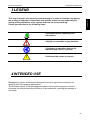
Please pay attention to the following icons:
It indicates further explaining and
information.
It highly recommends to pay attention.
It indicates an operation that can be
repeated many times, cyclically.
!
It indicates the norms to respect.
4 INTENDED USE
Management system of distribution designed to work on agricultural machinery for
spraying and crop spraying applications.
The accurate control of the operating parameters of the system sprayer or orchard
increases the effectiveness and efficiency of the treatments, reducing the wastage of
chemicals.
-3
ENGLISH
3 LEGEND
General Information
GeoSystem 250 RevA2
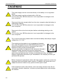
5 WARNING
!
The power supply must be connected directly to the battery or to a regulated
feeder.
The power supply must be protected with a 10A fuse.
If it is not the case, GEOline electronic is not responsible for damages to the
micro computer.
!
Disconnect the power supply cable from the micro computer when the battery is
undergoing recharge.
If it is not the case, GEOline electronic is not responsible for damages to the
micro computer.
!
Disconnect all lines from the local plant before undertaking welding on the
vehicle.
If it is not the case, GEOline electronic is not responsible for damages to the
micro computer.
!
!
4-
For a correct functioning, please make sure that the battery has always a higher
voltage than 10, 5 Volt.
This marking on the product or on its packaging illustrates
that, under European Directive 2002/96/EG governing used
electrical and electronic device, this product may not be
disposed of with normal household waste.
You are responsible for disposal of this equipment through a
designated waste electrical and electronic equipment
collection. To determine the locations for dropping off such
waste electrical and electronic, contact your government office, the waste
disposal organization that serves your household or the company at which you
purchased the product.
!
Before cleaning the agricultural vehicle with high pressure water jets, protect the
equipment from any possible water entrance. In addition, take great care not to
subject the devices, cables or any options to direct jets of water.
!
If the equipment needs to be cleaned, use a soft, damp, lint-free cloth. Do not
use sprays, solvents, abrasives, or sharp or pointed objects that could damage
the indicator.
General Information
GeoSystem 250 RevA2
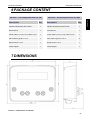
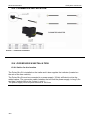
6 PACKAGE CONTENT
Description
Qty
8410038 - Kit GeoSystem 250 OS 4W
Description
Qty
Indicator GeoSystem 250 OS 2W
1
Indicator GeoSystem 250 OS 4W
1
Driver Box W
1
Driver Box W
1
Power cable L=3.5 m+ Com cable L=5 m
1
Power cable L=3.5 m+ Com cable L=5 m
1
Valve cable Type B L=1.2 m
4
Valve cable Type B L=1.2 m
6
Speed sensor L=5 m
1
Speed sensor L=5 m
1
Fixing Support
1
Fixing Support
1
Table 1- Package
7 DIMENSIONS
Picture 1 – Dimensions of indicator
-5
ENGLISH
8410037 - Kit GeoSystem 250 OS 2W
General Information
GeoSystem 250 RevA2
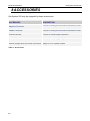
8 ACCESSORIES
GeoSystem 250 may be equipped by these accessories:
ACCESSORY
DESCRIPTION
Magnetic Flowmeter
A sensor to noting the flow and to calculate the litres
Paddle Flowmeter
A sensor to noting the flow and to calculate the litres
Pressure Sensor
A sensor to measuring the pressure
Level Sensor
A sensor to measuring the liquid level in the tank
Sucker hangers with mini VESA connection Hanger to fix in a glass surface
Table 2 - Accessories
6-
General Information
GeoSystem 250 RevA2
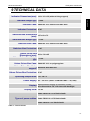
9 TECHNICAL DATA
Indicator Dimensions(mm): 192 x 163 x 55 (without fixing support)
ENGLISH
Indicator weight (gr): ~ 1000
Indicator Case: PA66 IGF 30 % native color RAL 9005
Indicator Protection: IP 67
Switches Box Dimensions
167 x 69 x 72
(mm):
Switches Box Weight (gr): ~ 1100
Switches Box Case: PA66 IGF 30 % native color RAL 9005
Switches Box Protection: IP 67
Valves Driver Box
210 x 130 x 45
Dimensions (mm):
Valves Driver Box Weight
~ 1100
(gr):
Valves Driver Box Case: PA66 IGF 30 % or polypropylene
Valves Driver Box fixing
Stainless steel AISI 304
support:
Valves Driver Box Protection: IP 67
Operating temperature: -20 / +65 °C
Power supply: 9,5 – 32 Vd.c. (alarm “LOW BATTERY” < 9,5 Vdc)
Alphanumeric display 16 column x 2 rows
Display: area dimensions 123 x 30.4 mm with backlight
Display view: > 2 mt
Cable FROR 18 x 0.75 black sheath
Types of power cables: Cable FROR 12 x 0.75 black sheath
Cable FROR 2 x 2.5 black sheath
Table 3 - Technical Data
-7
General Information
10
GeoSystem 250 RevA2
INSTALLATION OF COMPONENTS
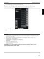
10.1 CONFIGURATIONS
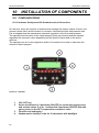
10.1.1 Indicator GeoSystem 250 Orchard version 2/4 sections
On the front, there are a series of switches that manage the section valves of boom, the
general control valve and the switch to increase / decrease the flow and pressure rate.
It is envisaged also the manual and automatic regulation of the flow and pressure.
The operator sets the value of the liquid sprayed (liters per hectare) and the indicator
regulates the volumetric valve depending on the speed of travel and on the active
sections.
The operator can act on the regulation switch if he wants to increase or decrease the
amount of liquid sprayed.
Picture 2 – Indicator
1.
2.
3.
4.
8-
ON / OFF key.
Series of switches in 2 positions (ON-OFF) to control the general valve
and section valves (2 or 4). 1 switch with 3 positions (ON-OFF-ON) with
spring return in the OFF command for volumetric valve
Function and setting key
Alphanumeric display 2 rows for 16 characters with backlight.
Configuration
GeoSystem 250 RevA2
ENGLISH
The system is supplied with pre-drilled mounting bracket. It is provided for a MED
fastening system (optional) with dedicated accessories.
The system is able to shore up a maximum load of 2.5 Kg.
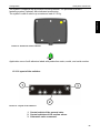
Picture 3 - Back side of the indicator
Application zone of self-adhesive labels with production codes, model, and serial number.
10.1.2 Layout of the switches
Picture 4 - Layout of the switches
1. Control switch of the general valve
2. Control switches of the section valves
3. Volumetric valve command.
-9
General Information
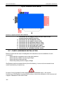
10.2 CONNECTIONS SCHEME
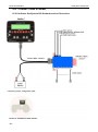
10.2.1 Indicator GeoSystem 250 Orchard version 2/4 sections
Picture 5 - Scheme Orchard Version
10 -
GeoSystem 250 RevA2
Configuration
GeoSystem 250 RevA2
10.3 COMPUTER INSTALLATION
The computer GeoSystem must be positioned in the command cabin of the farm vehicle
taking care to observe the following precautions:
-
Make sure that the monitor is not placed in areas subject to vibrations or crashes,
this could damage the equipment or activate the buttons unintentionally;
Fix the device in a place that is visible and easy to reach with your hands.
The monitor should not obstruct the movement or limit the control visibility.
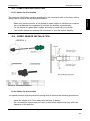
10.4 SPEED SENSOR INSTALLATION
Picture 6 - Proximity Installation
10.4.1 Advice for the location
The speed sensors must be positioned taking care to observe the following precautions:
-
Install the sensor at 4-5 mm away from the body to detect;
Do not install the sensor body too near to other metal objects that may affect the
operation of the detector.
- 11
ENGLISH
10.3.1 Advice for the location
General Information
GeoSystem 250 RevA2
10.5 FLOWMETER INSTALLATION
Picture 7 - Flowmeter Installation
10.6 DRIVER BOX W INSTALLATION
10.6.1 Advice for the location
The Driver Box W is installed on the trailer and it also supplies the indicator (located on
the cab of the farm vehicle).
The Driver Box W must be connected to a power supply (12Vdc) sufficient to drive the
added valves. The connection cable, between the box and the power supply, is long 3,5m
and has 2 eyelets M8 on the 2 wires (+ and -).
The power supply must be protected with a 10A fuse.
12 -
Configuration
GeoSystem 250 RevA2
10.6.2 Cables connecting DRIVER BOX W
ENGLISH
The Driver Box W performs the operations to the command valves group.
It has a series of interface connectors for sensors and actuators
Picture 8 - Driver Box W
Features:
It contains the wiring board with sensors and control outputs for the activation of the
solenoid valves 2-wire.
This board is connected to the indicator via a multipolar cable 5 meters long.
2 digital inputs (counter NPN):
- speed sensor (including in the packaging)
- flowmeter
2 analogical inputs 4-20 mA:
- pressure sensor of the circuit
- tank level sensor.
The cable allow to feed the power supply and it presents the signal cables for the
communication and the sensor cables.
- 13
General Information
GeoSystem 250 RevA2
Layout connectors Driver Box W:
Picture 9 - Layout connectors Driver Box W
1. Connector for the supply cable and the cable for the
communication with the monitor
2. Connector for the Flowmeter cable
3. Connector for the speed sensor cable
4. Connector for the pressure sensor cable
5. Connector for the tank level sensor cable
6. Connector for the principal valve cable
7. Connector for the proportional valve cable
8. Connectors for command section valves
10.7 CHECK HARDWARE INSTALLATION
Before to start with the use of GeoSystem 250 check the correct installation of each
component:
•
Check that the connectors are in the right locations
•
Check that the cables have the right length
•
Check that all screws are tight
•
Check the polarity and the supply voltage
GeoSystem must be powered directly from the battery, it must not be connected to an
outlet controlled by a master key.
In case of use of groups of valves equipped with a calibrated return, the correct
functioning of GeoSystem is guaranteed only by an accurate calibration of all sensors and
a proper calibration of the return flows.
14 -
Configuration
GeoSystem 250 RevA2
ENGLISH
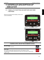
11 INTERFACE DESCRIPTION OF
INDICATOR
11.1 TABLE LIST OF BUTTONS AND SWITCHES AND THEIR
FUNCTIONS
Monitor with alphanumeric display, buttons and
command switches
Picture 10 – Indicator with 2 sections
Picture 11 – Indicator with 4 sections
CONTROL KEYS, SELECTION OR MODIFICATION
ON / OFF key:
Turn on / off the indicator
RATE key:
It is used to temporarily change the value of the amount of flow.
The value is not stored, taking up the current work (Set key) is reset to the
original value.
- 15
General Information
GeoSystem 250 RevA2
Key command:
- Allows to returns to the previous menu
- Reset the percentage of increase / decrease of the value distribution
- Allows to reset the counters of the current treatment
UP key:
- It flows through the individual entries to the previous menu
- Increase the value of the parameter
During the modification of parameters, pressing the button permit to
increase quickly the input values
DOWN key:
- Scrolls through the individual items through to the next menu
- Decrease the value of the parameter
During the modification of parameters, pressing the button permit to
decrease quickly the input values
Confirm key:
- Confirm the access to the selected menu or parameter value previously
modified
- Holding down this button for more than 2 seconds, it permit to display the
values of the stored treatments
Command key:
Enable / disable the automatic adjustment of the distribution
ROW key:
It is used to temporarily change the value of the width between rows.
The value is not stored, taking up the current work (Set key) is reset to the
original value.
Command key:
Allows to enable the menu of the working parameters.
16 -
Configuration
GeoSystem 250 RevA2
11.2 MENU STRUCTURE
ENGLISH
GeoSystem 250 menu are shown in the figure, in order to enter in the various items press
the buttons or combinations of buttons located on the front panel of the monitor.
Figure 12 – Menu map
- 17
Configuration
GeoSystem 250 RevA2
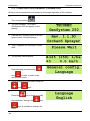
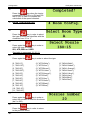
11.3 CONFIGURATION GENERAL PARAMETERS
Allows to set the parameters necessary for the proper operation of the indicator.
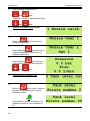
1
Turn on by pressing
.
2
The first message “TECOMEC
GeoSystem 250” will appear on the
display
3
It shows the Firmware revision and the
system name: Orchard Sprayer.
4
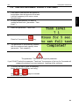
Then, it appears the message “Please
Wait”
5
The working values appear.
6
Keep pressing simultaneously
and
in order to enter in the
configuration menu.
7
Scroll through the menu items using the
and
keys.
8
Press the
key in order to modify
the parameter: through the
and
keys is possible to change the
value.
18 -
Configuration
GeoSystem 250 RevA2
pressing
and
keys.
If the input value is numeric, it will be increased or decreased according to the duration
of the key press with an exponential interval.
It is possible to cancel the current selection or return to the previously menu by
pressing the
key.
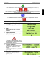
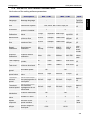
11.3.1 LIST OF MENU ITEMS OF GENERAL CONFIGURATION
1
Language:
Italian/English/Spanish/German/French.
2
Units:
Metrics (l/ha, Km/h, bar) / US (GPA,
mph, psi).
3
Vehicle identification:
(1-5) it identifies the vehicle on which
the system is installed.
* By entering this configuration, you set
the parameters for that particular vehicle
(in this example: vehicle 1).
4
Flowmeter calibration:
It specifies how many pulses arrive to
the flowmeter per amount of liquid
sprayed.
1-5000 pulse/liter (Metric) or pulse/USG
(gallon) (US).
5
Alarm threshold minimum flow:
0-10000 l/min (Metric) or USGpm
(gal/min) (US)
- 19
ENGLISH
If the fields contains default values or names, they will be displayed recursively by
Configuration
6
Alarm threshold maximum flow:
0-10000 l/min (Metric) or USGpm
(gal/min) (US).
7
Speed sensor calibration:
2 mode: Constant wheel = distance
traveled (cm or inches) / (number of
pulses per revolution * wheel speed) or
Automatic over a distance of 100 meters
it is acquired pulse count.
8
Sensor pressure calibration:
0-200 F.S. value (bar or psi).
9
Tank capacity:
0-10000 liter (Metric) or USG (gal) (US).
10
Alarm threshold minimum tank level:
0-10000 liter (Metric) or USG (gal) (US).
11
Simulated speed:
Yes/No.
12
Simulated speed value:
0-50 Km/h (metric) or mph (U.S.)
13
Minimum speed threshold:
0-50 Km/h.
Below this value, it stops the spraying.
14
Manual speed threshold:
0-50 Km/h.
Below this value, it is not carried out the
automatic management (only manual).
15
Pressure calculation:
Yes/No.
20 -
GeoSystem 250 RevA2
Configuration
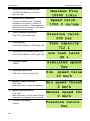
16
GeoSystem 250 RevA2
Number of section valves:
2, 4
Sensitivity to change in velocity:
ENGLISH
17
it changes the response time of the flow
rate control in function of the speed,
from the value 1 (fast) to the value 5
(slow).
By increasing this value, you will
increase the precision but you will
reduce the speed variation.
18
Specific weight liquid tank:
Only if the presence sensor level = YES,
it allows to calculate the level of the tank
in function of the specific weight of the
liquid inside.
19
Presence sensor level:
If you choose YES, the measured level
is used in the replenishment procedure
of the tank,. If you choose NO, it shows
the pre-setting value.
Press the
new value.
20
button to fill in the
Percentage value of the display
tolerance:
It determines the sensitivity to display.
21
Section valves type:
• It is dependent (D) if, by closing
the general valve, the other
valves are closed; the led are
switch off with the switches in any
position. By re-activating the
general valve, the other valves
are re-activated and the switches
are in ON position
• It is independent (I) if the section
valves stay opened also if the
general valve is closed.
- 21
Configuration
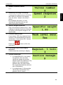
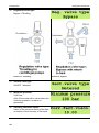
22
GeoSystem 250 RevA2
Regulation valve type:
Bypass / Throttling
Picture 13 - Throttling
23
Section valve type:
ON-OFF / Metered
24
Minimum pressure:
0-200 bar
After 30 seconds with a value below the
minimum pressure, an alarm is
generated..
25
Viscosity corrective factor:
Value of the corrective factor of the flow
in function of the viscosity of the liquid.
22 -
Picture 14 - Bypass
Configuration
GeoSystem 250 RevA2
11.4 CONFIGURATION WORKING PARAMETERS
It allows to set all the working parameters of each single vehicle.
Turn on by pressing
ENGLISH
1
.
2
The first message “TECOMEC
GeoSystem 250” will appear on the
display.
3
It shows the Firmware revision and the
system name: Orchard Sprayer.
4
Then, it appears the message “Please
Wait”.
5
The working values appear on the
display.
6
Press
key in order to enter in the
working selection/configuration menu.
7
Press the
and
keys in
order to choose the type of work and
confirm pressing
key.
It is possible to configure and choose up
to 10 different types of work.
- 23
Configuration
GeoSystem 250 RevA2
8
Keep pressing again the
key to
pass through the following programs.
It is possible to cancel the current
selection by pressing
key.
11.4.1 LIST OF ITEMS OF WORKING PARAMETERS
1
Dosage setting:
it permits to set the current value of the
amount of liquid per unit of surface (liters
per hectare).
2
Press the
button to enter in the
parameter and to set the value using the
and
3
keys.
Row Width:
It allows to set the value of row width in
function of corresponding value.
4
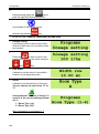
Boom:
It allows to set the identifier of the boom.
You can choose the value from "A" to
"J"
If the parameter "Number of Valves" is
equal to 4, the voices relating to Boom
are 2:
1. Boom Type (1-4)
2. Boom Type (2-3)
More information to paragraph 11.7
24 -
Configuration
GeoSystem 250 RevA2
11.4.2 EXECUTION WORKING CYCLE
It concerns the data management during the operating cycle. The indicator performs,
according to the parameters configured, the acquisitions of the measures on the various
sensors and the adjustment required.
Turn on the indicator by pressing
2
ENGLISH
1
.
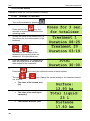
The current dosage values appears and,
in parentheses, those specified. In the
bottom line the speed of advancement of
the vehicle.
This visualization is available during the
work.
3
The indicator displays the single values measured and calculated through
&
keys.
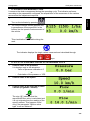
11.4.3 LIST OF AVAILABLE VALUES IN THE WORKING CYCLE
1
Current value of the pressure
It is displays only in this situations:
- Value of pressure calibration ≠ 0
or
- Calculation of the pressure = YES
2
Current value of the speed
3
Current value of the flow rate in liters
/ minute (or gallons / minute)
The sign “@” indicates that the
represented flow value is calculated and
it is not originate from the reading of the
specific sensor. This happens if and
only if the parameter “Section valve
type” is set as “Metered”.
- 25
Configuration
GeoSystem 250 RevA2
4
Extension of the treated area since
the beginning of treatment
5
Total of the liquid sprayed since the
beginning of treatment
6
Current level of the tank:
this parameter allows to do the 2
following operations.
Press the
key if you want to
modify the tank value using the
and
keys.
Press again the
the value.
key to confirm
During the increase of the value, if you
keep pressed the
key without
releasing it, the value will increase and
after 30 units it will pass to tens to
accelerate the operation.
Keeping pressed the
key for 5
seconds to set the initial tank capacity (
see the Tank Capacity parameter).
If the level sensor parameter is YES the
value set will be the level measured by
the sensor. After the 5 seconds a
massage appears : Completed!
7
26 -
Duration of the last treatment
(hh:mm)
Configuration
8
GeoSystem 250 RevA2
Traveled distance since the
beginning of the last treatment (Km)
ENGLISH
9
At the end of the menu, you return to the
initial display of the current dosing and
those specified.
10
Press and hold the
key for 5
seconds in order to reset, anytime, all
counters related to the ongoing
treatment.
After the 5 seconds, a message
appears: Completed!
key before the 5
Release the
seconds to cancel the reset.
11.5 WAY OF CALIBRATION AND BOOM CONFIGURATION
These operations must carried out when the treatment is not active (in manual mode
and with all the switches in the OFF position).
- NOZZLE CALIBRATION:
It allows to define the characteristics of the type of nozzle used (liter/minute) in
function of the pressure (bar). It is possible to choose from a set of pre-configured
identifying marks (ISO standard) or to define new ones.
- TANK LEVEL CALIBRATION:
It sets the calibration points related to the level sensor of the tank.
- SPEED SENSOR CALIBRATION:
It calculates the rate constant based on a known distance to travel (100 m in EU and
300 feet in US).
- SPRAYING BOOMS CONFIGURATION:
It allows to define the number and the type of nozzles for each type of spraying
booms.
1
Turn on the indicator by pressing
.
- 27
Configuration
2
GeoSystem 250 RevA2
Keep pressing simultaneously
and
keys.
Slide the 4 voices of calibration through
and
3
keys.
NOZZLE CALIBRATION (max 8).
4
Press the
key to enter in the
nozzle configuration.
5
Press again the
key to set up to
5 pairs of calibration values (Set 1-5)
related to the nozzle.
6
Press again the
key to set the
Pressure and the Flow Rate using the
and
7
keys.
TANK LEVEL CALIBRATION
8
Press the
key in order to enter in
the tank configuration and to set the
calibration points.
It is possible to define a minimum of 2
calibration points up to a maximum of
25.
28 -
Configuration
GeoSystem 250 RevA2
9
and
ENGLISH
Press again the
key in order to
insert the Tank level in liters using the
keys.
Pour clean water (in the previously fitted
amount of it) into the tank and confirm it
with the
key in order to move to
the next value.
10
Definition of the second value.
Completely repeat the operations of the
step 9.
11
Perform the steps 9 and 10 until the definition of all the calibration points you want to set
(max 25).
12
Press the
the calibration.
key in order to finish
If everything is successful, it appears
the message “Completed!”.
13
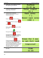
SPEED SENSOR CALIBRATION
14
Press the
calibration.
15
key to enter into the
The message “Counter value” appears,
it will increase as the tractor moves
towards the finish line.
- 29
Configuration
GeoSystem 250 RevA2
16
Press the
key when the tractor
crossed the line (100 m in EU and 300
feet in US) in order to complete the
calculation of the speed constant.
17
BOOM CONFIGURATION
18
Press the
key in order to select
the type of boom that identifies with the
character from “A” to “J”.
19
Press again the
key in order to
select the type of nozzle:
ISO, ATR, MGA or USER
See table to paragraph 19, 20, 21
20
Press again the
key in order to select the type:
{0, "ISO-01"},
{1, "ISO-015"},
{2, "ISO-02"},
{3, "ISO-025"},
{4, "ISO-03"},
{5, "ISO-04"},
{6, "ISO-05"},
{7, "ISO-06"},
{8, "ISO-08"},
{9, "ISO-10"},
{10, "ISO-15"},
{11, "ISO-20"},
{0, "ATR-White"},
{1, "ATR-Lilac"},
{2, "ATR-Brown"},
{3, "ATR-Yellow" },
{4, "ATR-Orange"},
{5, "ATR-Red"},
{6, "ATR-Grey"},
{7, "ATR-Green"},
{8, "ATR-Black"},
{9, "ATR-Blue"},
21
Press again the
key in order to
select the number of nozzle in the boom
(da 0 a 200) .
22
Press the
key in order to return
to the previous menu.
30 -
{0, "MGA-White"},
{1, "MGA-Golden"},
{2, "MGA -Orange"},
{3, "MGA-Green"},
{4, "MGA-Yellow"},
{5, "MGA-Lilac"},
{6, "MGA-Blue"},
{7, "MGA-Red"},
Configuration
GeoSystem 250 RevA2
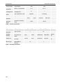
11.6 VALUE OF SOFTWARE PARAMETERS
Limit values of the setting software parameters.
Description
Language
Message language
Unit
Used metric system
Min. / U.M.
Max. / U.M.
-
-
l/ha, Km/h, bar o GPA, mph, psi
Note
ENG/
ITA/SPA/
DEU/FRA
Metrics/
US
Maximum
flow
Vehicle on which the
system is installed
Constant Flowmeter
Value
Alarm threshold
minimum flow
Alarm threshold
maximum flow
Speed
Calibration
Speed sensor
calibration
0.0
cm/imp
0.0 in/imp
6000.0
cm/imp
2362.2
in/imp
Pressure
Calibration
Pressure sensor
calibration
0 bar
0 PSI
200 bar
2901 PSI
Tank capacity
Value the tank can
contain
0l
0 USG
10000 l
2642 USG
Minimum
Tank level
Alarm threshold
minimum level tank
0l
0 USG
10000 l
2642 USG
Simulated
speed
Simulated speed
Simulated
speed value
Simulated speed
value
0 km/h
0 mph
50 km/h
31 mph
Metrics/
US
Threshold
minimal
speed
Value below which
the spraying action is 0 Km/h
interrupted
0 mph
50 Km/h
31 mph
Metrics/
US
0 mph
50 Km/h
31 mph
Metrics/
US
ID Vehicle
Flowmeter
Calibration
Minimal flow
Value below which
Threshold
the automatic
manual speed management is not
effectuated
Pressure
Pressure calculation
calculation
Number of
Number of valve
valve
Speed
response
Specific
weight
Sensitive to the
speed variation
specific weight of
tank liquid
1
5
18927
imp/USG
2642
10000 l/min
USGpm
2642
10000 l/min
USGpm
1 imp/l
4 imp/USG 5000 imp/l
0 l/min
0 USGpm
0 l/min
0 USGpm
No
0 Km/h
Metrics/
US
Metrics/
US
Metrics/
US
Round
pulse
Num. *
wheel
rounds
Value of
bottom
scale
Metrics/
US
Metrics/
US
Yes
No
Yes
2
4
2, 4
1
5
1 fast
5 slow
0.00
10.00
- 31
ENGLISH
Parameter
Configuration
Level sensor
% tolerance of
regulation
Sections
management
Regulation
valve
Section valve
Minimum
pression
Corrective
viscosity
factor
GeoSystem 250 RevA2
Level sensor
NO
Yes
Value % of tolerance
0%
20 %
D
I
Type regulation valve
Bypass
Throttling
Type section valve
On-Off
Calibrated
Sections
management
0 bar
Corrective viscosity
factor
0 psi
200 bar
0.00
2901 psi
10.00
Table 4 - General Parameters
Parameter
Working
selection
Dosage
setting
Width row
Boom type
Description
Max. / U.M.
1
10
Type of work
Current value of
the amount of
0 l/ha
liquid
Distance between
0.00 mt
the rows
Boom type
associated to
sections
Table 5 - Working Parameters
32 -
Min. / U.M.
Note
0 GPA
10000 l/ha
1069 GPA
Metrics/
US
0.00 ft
100.00 mt
328.08 ft
Metrics/
US
A
J
Configuration
GeoSystem 250 RevA2
ENGLISH
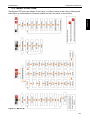
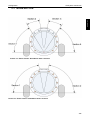
11.7 BOOM SECTION
Picture 15 – Boom section. Distribution with 4 sections
Picture 16 – Boom section. Distribution with 2 sections
- 33
Use
GeoSystem 250 RevA2
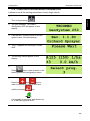
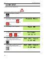
12 HW TEST
It allows to effect the hardware test.
This test can be carried out only at starting.
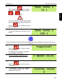
1
Turn on the indicator by pressing
.
2
After viewing the software revision, when
the message “Please Wait” appears,
press simultaneously the
and
keys.
3
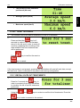
The message “Test HW” appears.
4
The value of Voltage appears and it is
possible to slide the following values
through
and
keys.
5
The next data is the value of the analog
input 1 of the Switch Box board
corresponding to the pressure sensor.
6
The next data is the value of the analog
input 2 of the Switch Box board
corresponding to the tank level sensor.
34 -
GeoSystem 250 RevA2
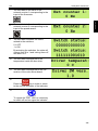
7
The next data is the value of the
external counter 1 corresponding to the
input of the flowmeter.
8
The next data is the value of the
external counter 2 corresponding to the
input of the speed sensor.
9
The next data indicates the status
related to the switches.
ENGLISH
Use
0 = OFF
1 = ON
By actuating the switches, the state will
change from 0 to 1 and turning them off
will return to 0.
10
The next data corresponds to the
temperature inside the box driver.
11
The next data corresponds to the SW
revision of the valve driver board.
12
Press the
key in order to return
to the normal operation of the indicator.
13
To repeat the TEST HW it is necessary
to switch off and on again the indicator.
- 35
Use
GeoSystem 250 RevA2
13 USE OF GEOSYSTEM 250
13.1 DISPLAY
Figure 17 -Display
13.2 DEFINITION OF TREATMENT
The term treatment means the set of data recorded during an activity of weeding or
sprayer. The working parameters recorded by GeoSystem are stored in a tail. The tail can
store a maximum of 20.
The data of each treatment can be visualized through the appropriate keys.
Every time you start a new treatment the data of the current treatment are inserted in the
tail.
The treatment number 1 is the last treatment saved.
Treatment number 2 is the second last treatment saved and so on.
All treatments inserted in the queue slip of a position at the moment of every saving.
When the tail is full, the recording of a new treatment causes the cancellation of the
treatment less recent (that in twentieth position).
After the treatment n° 20, appears the value “Total”, that refers to the historical data
related to all the treatments.
This value cannot be deleted, not even through the RESET procedure.
36 -
Use
GeoSystem 250 RevA2
13.3 NEW TREATMENT
To start the recording of data on a new
treatment, select a parameter of any work
cycle, with the exception of the
parameter: "Tank Level".
ENGLISH
1
2
Press the
3
key for 5 seconds.
By now, the counters are all reset.
The parameter “Tank level” is a special parameter:
If it is selected, the pressing of the button for 5 seconds DO NOT prepare the system for a
new treatment but for a new filling of the tank.
13.4 TURNING ON GeoSystem 250
1
Turn on the indicator by pressing
.
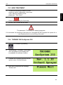
2
The message “TECOMEC GeoSystem
250” will appear on the display and
immediately the software revision.
3
It shows the Firmware revision and the
system name: Orchard Sprayer.
4
After which it appears the message
“Please wait”
- 37
Use
GeoSystem 250 RevA2
5
If the general valve is active ( switch in
ON position),when you are turn on the
indicator, it will appear a message and
then a sound of the buzzer to demand
your attention.
Disable the switch to interrupt the alarm.
6
The working values appears on the
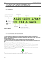
display and, eventually, additional
markings such as:
7
• the character “M” before the
current value of distribution
“M 125 l/ha”: it signals that the
indicator is in manual mode;
8
• the character “A” before the
current value of distribution
“A 125 l/ha”: it signals that the
indicator is in automatic mode.
9
• the sign “►”at the bottom left:
it signals that the treatment is in
action.
10
• the sign “▌▐” at the bottom
left: it signal that the treatment is
in pause.
11
• the number “3” at the bottom
left: it identifies the type of work
you are doing
12
• the sign “@”: it indicates that the
data represented on the right is
calculated or simulated and it is
not originated from the reading of
one specific sensor. E.g. the
represented speed is a simulated
value.
38 -
Use
GeoSystem 250 RevA2
13
14
ENGLISH
• The symbol
in the upper
right: it indicates the presence of
an alarm;
At the starting, press simultaneously the
keys to
reset all the parameters of the indicator
to the initial values.
13.5 TURNING OFF GeoSystem 250
1
Press the
the system.
2
key in order to turn off
Wait that the data of the last treatment
will be saved.
During the turning off do not press any key and do not remove the power, until the control
unit turns off.
Always use the appropriate button to turn off the computer, otherwise all the data relating
to treatments and schedules will be lost.
13.6 PREPARATION
1
Make sure all the switches are in OFF
position.
2
Turn on the indicator by pressing the
key.
3
Set in GeoSystem the amount of the
liquid that is in the tank.
- 39
Use
GeoSystem 250 RevA2
4
To start the data recording of a new
treatment, select a parameter of the any
cycle work, with the exception of the
parameter” tank level”.
5
The system store the treatment data in a
tail of 20 elements.
6
Press for 5 seconds the
key to
save the last data stored in the tail and
to reset all the meters, prearranging the
data recording of the new treatment you
will do.
N.B. if the level sensor is not present,
pressing the key, you will reset all the
working data, except the tank level that
is recharged to the pre-set value during
the configuration phase.
13.7 AUTOMATIC FUNCTIONING
The automatic functioning is indicated by the letter A, situated on the left side of the
display. The value between parenthesis is the dosage set by the user, GeoSystem 250 will
drive the regulation valve looking for maintaining constant the dosage at the variation of
the vehicle speed.
13.8 MANUAL FUNCTIONING
The manual functioning is indicated by the letter M, situated on the left side of the display.
GeoSystem 250 will record the working data shown during the functioning.
40 -
Use
GeoSystem 250 RevA2
1
If the field to treat requires an amount of
liquid higher than the amount of the tank,
it will be necessary to fill once or more
times the tank.
2
At every replenishment you have to
update the tank level ( parameter: “Tank
Level ”)
3
Select the parameter: “Tank Level”
ENGLISH
13.9 TANK REPLENISHMENT DURING A TREATMENT
4
Press for 5 seconds the
5
key.
The parameter is automatically updated
with the maximum tank capacity value.
(parameter “Tank capacity”)
The parameter “Tank level” is a special parameter:
if you DO NOT select the parameter “Tank level” the pressure of the key for 5 seconds will
prepare the system for a new treatment, resetting all the counters.
6
To modify the value, enter in modifying
phase pressing the OK key and using
the
and
keys to increase
or decrease the value.
- 41
Use
GeoSystem 250 RevA2
13.10 TOTALIZERS
It allows to check the counters related to working.
13.10.1
READING TOTALIZERS
1
Turn on the indicator by pressing
.
2
Press and hold the
key for 3
seconds to access the statistics of the
operating mode.
3
Shows the name of the totalizer and, at
the bottom line, the total duration of the
treatment.
4
Scroll the last 20 treatments through
and
keys.
The totalizer N° 1 relates to the
treatment more recently while the
totalizer N° 20 is the oldest one.
5
After the treatment n° 20, appears the
total value that refers to the historical
data related to the treatments.
6
Press the
Through
out, such as:
key to verify the individual counts of each totalizer.
and
keys, display the values relating to the treatment carried
• The value of the treated area
(ha)
• The value of the total liquid
sprayed (l)
• The traveled distance (Km)
42 -
Use
GeoSystem 250 RevA2
• The duration of the treatment
performed (hh:mm).
ENGLISH
• Average speed (km/h)
• Maximum speed (km/h)
13.10.2
1
RESET TOTALIZERS
The indicator stored the data of treatment in a tail of 20 elements.
2
Press and hold the
key for 5
seconds in order to save the last data
stored in the tail and in order to reset all
counters, preparing the recording of the
data related to the new treatment that
will be performed.
key to confirm the reset or
Press
key to cancel.
If the level sensor is not present, pressing the reset button will reset all work data, except
the tank level, which is reloaded to the preset value during configuration.
13.11 RECALL DATA OF TREATMENTS
1
Press for 3 seconds the
key, in
order to access to the menu that allows
to visualize the tail of last 20 treatments
performed.
2
Using the
and
keys in order to scroll the list of treatments. Press the
key in order to access to the content.
- 43
Use
GeoSystem 250 RevA2
14 ALARMS
14.1 WARNING AND ALARMS
There are some warning and alarms to highlight unusual states that show anomaly
functioning.
At the activation o fan alarm, you will hear the buzzer.
Press
key to disable it.
The active alarm state is highlighted by the
sign
on the right of the first line of the
display.
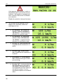
14.2 LIST OF POSSIBLE ALARMS
1. Valve box alarm:
There is no communication between the
indicator and the Valve Box.
2. Flow regulation alarm:
the indicator has to reach a flow set point
value(l/ha), if it can not reach this value, the
indicator gives a signal after a minute.
3. Tank empty alarm:
it gives this alarm when it reaches the
minimum flow of liquid in the tank set with
the parameter Alarm threshold minimum
tank level
4. Minimum flow alarm:
The amount of sprayed liquid (l/min) is
lower than the parameter value Alarm
threshold minimum flow
5. Maximum flow alarm:
the amount of sprayed liquid (l/min) is
higher than the parameter value Alarm
threshold maximum flow
6. Low battery level alarm:
the battery level is lower than 9.0 Volts
7. Low pressure alarm:
The alarm is generated after 15 seconds
with a pressure less than the parameter
Minimum pressure
44 -
Use
GeoSystem 250 RevA2
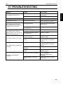
15 TROUBLESHOOTING
CAUSE
SOLUTION
There is not power.
Check the connections on the
power cable.
The indicator is turned off.
Press the turning on button.
The valves are not connected.
Connect the connectors
The valve has not power.
Check the electric connection and
the functioning of the valve
Wrong programming
Check the connection with the
speed sensor.
The reset of the totalizer has not
been effectuated
Reset the totalizer
Wrong programming
Check the bar width programming
The reset of the totalizer has not
been effectuated
Reset the totalizer
The indicator has not signal from
the pressure sensor
Check the connections with the
pressure sensor
Wrong installation of the pressure
sensor
Check the bottom scale
programming for the pressure
sensor
Wrong programming
Check the bottom scale
programming for the pressure
sensor
The pressure sensor is not
calibrated
Do the calibration
Wrong installation of the pressure
sensor
Check the connections with the
pressure sensor
The level sensor is not calibrated.
Do the calibration.
Repeat the level sensor
calibration.
Wrong installation of the level
sensor.
Check the connection with the
level sensor
The display does not turn on
The valves can not be controlled
A valve does not open
The counting of the travelled
distance shown on the computer
is different from the real one.
The counting of the travelled
surface shown on the computer is
different from the real one.
The instant pressure is not shown.
The instant pressure visualized is
inaccurate.
The tank level visualized is
inaccurate.
ENGLISH
DISPLAY
Table 6 - Troubleshooting
- 45
Use
GeoSystem 250 RevA2
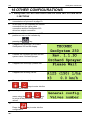
16 OTHER CONFIGURATIONS
16.1 GeoSystem 250 4OS INSTALLATION ON SPRAYER SYSTEM WITH
2 SECTIONS
1
Make sure the system is exactly
connected as on picture 8 at page 10.
2
In this step it is not important the sensor
connection but the valve cable
connection and the GeoSystem 250
driver box output connection.
3
Make sure all the switches are in OFF
position so turn on the indicator by
pressing the
key.
4
It appears the message TECOMEC
GeoSystem 250 on the display.
5
It shows the Firmware revision and the
system name: Orchard Sprayer.
6
It appears the message “please wait”
7
It appears the working values.
8
Press simultaneously the
9
and
keys to enter into the
configuration menu.
Scroll up and down the entries of the
menu using the
and
keys
to arrive at the parameter “ number of
valves”
10
Press the
configuration.
46 -
key to enter into the
Use
GeoSystem 250 RevA2
Go to the next step to verify the operation of the valves otherwise skip to step number 15.
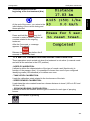
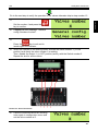
ENGLISH
11
Set the number 4 and press the
key to confirm.
12
It appears a new message “ General
config. Number of valves”.
13
Press the
key to exit and to
launch again the indicator.
14
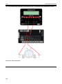
When the indicator is on working mode, activate the switch number 1 ( in ON
position) and check the valve number 1 is working.
Then, disable the Switch 1 ( in OFF position) and try with the Switch number 2.
Repeat the test for all the valves.
Picture 18 - Use of 4 sections
15
If all the connected valves are working,
enter again in configuration menu and
set the valve number at 2.
- 47
Use
16
GeoSystem 250 RevA2
At this point the indicator is working with only 3 connectors as indicated on picture:
Picture 19 - Use of 2 sections
48 -
Rules
GeoSystem 250 RevA2
Company:
GEOline electronic
Address:
Via Mondadori, 15
46025 Poggio Rusco (MN)
ITALY
ENGLISH
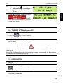
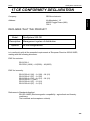
17 CE CONFORMITY DECLARATION
DECLARES THAT THE PRODUCT:
Model:
GeoSystem 250 OS
Description:
Options:
Management system of distribution
All the configurations
is in conformity with all the essential requirements of European Directive 2004/108/EC,
making with the following directives:
EMC for emission:
EN 61326-1
EN 55011(1999) – A1(2000) – A2(2003)
EMC for immunity:
EN 61000-4-2 (96) – A1 (99) – A2 (01)
EN 61000-4-3 (97) – A1 (02)
EN 61000-4-4 (96) – A1 (01) – A2 (01)
EN 61000-4-5 – (1997)
EN 61000-4-6 (97) – A1 (01)
EN 61000-4-8 (97) – A1 (01)
Reference to Standards Applied:
EN ISO 14982 (Electromagnetic compatibility - agricultural and forestry
machinery.
Test methods and acceptance criteria)
- 49
Rules
GeoSystem 250 RevA2
18 GUARANTEE
The supplier guarantees, for 24 months from the delivery date, the good quality of materials used, the
excellent construction and the steady functioning of the instrument they have manufactured and that bears
the trademark or the production serial number. During the guarantee period the supplier undertakes to repair
or replace, free supplier’s head office, faulty parts due to poor materials or faulty construction, provided that
such parts are delivered free port supplier’s head office.
Shortcomings and defects due to incorrect use of instruments, inadequate maintenance, changes carried out
without the supplier’s approval, normal wear are not included in this guarantee.
Liability and compensations by the supplier due to direct or indirect damages to persons, objects or
production, even as a consequence of faulty functioning of the supplied instruments or of material or
construction defects, are not included in this guarantee.
NOTES:
GEOline electronic reserve itself the right to modify the contents of this manual caused by hardware and software implementations in
order to a constant improvement of the product and so a better service to the user.
50 -
Rules
GeoSystem 250 RevA2
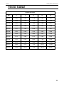
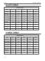
19 ISO TABLE
NOZZLE [l/min]
bar
4
8
12
16
20
ISO-01
0.45
0.64
0.78
0.91
1.01
ISO-015
0.68
0.96
1.18
1.36
1.52
ISO-02
0.92
1.30
1.60
1.85
2.07
ISO-025
1.15
1.63
2.00
2.31
2.89
ISO-03
1.37
1.94
2.38
2.75
3.07
ISO-04
1.82
2.58
3.16
3.65
4.08
ISO-05
2.28
3.22
3.94
4.55
5.09
ISO-06
2.73
3.86
4.72
5.45
6.09
ISO-08
3.70
5.23
6.40
7.39
8.26
ISO-10
4.62
6.53
8.00
9.24
10.33
ISO-15
6.84
9.79
12.0
13.86
15.49
ISO-20
9.24
13.06
16.0
18.48
20.66
Table 7 - ISO table
- 51
Rules
GeoSystem 250 RevA2
20 ATR TABLE
NOZZLE [l/min]
bar
3
9
15
20
25
ATR-White
0.22
0.38
0.45
0.52
0.58
ATR-Lilac
0.28
0.48
0.61
0.70
0.77
ATR-Brown
0.38
0.64
0.81
0.93
1.04
ATR-Yellow
0.57
0.97
1.25
1.44
1.61
ATR-Orange
0.77
1.32
1.69
1.94
2.16
ATR-Red
1.08
1.83
2.33
2.67
2.97
ATR-Grey
1.18
1.98
2.51
2.88
3.20
ATR-Green
1.40
2.35
2.99
3.42
3.80
ATR-Black
1.57
2.64
3.36
3.85
4.28
ATR-Blue
1.92
3.24
4.12
4.72
5.25
Table 8 - ATR table
21 MGA TABLE
NOZZLE [l/min]
bar
4.83
6.89
10.34
13.79
20.68
MGA-White
0.25
0.29
0.34
0.40
0.50
MGA-Golden
0.33
0.39
0.46
0.56
0.63
MGA-Orange
0.50
0.59
0.68
0.82
0.88
MGA-Green
0.75
0.90
1.05
1.25
1.53
MGA-Yellow
1.00
1.20
1.42
1.65
2.03
MGA-Lilac
1.25
1.50
1.81
2.07
2.51
MGA-Blue
1.50
1.80
2.20
2.50
3.00
MGA-Red
2.10
2.55
3.10
3.50
4.30
Table 9 - MGA table
52 -
GeoSystem 250 RevA2
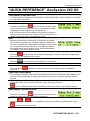
“QUICK REFERENCE” GeoSystem 250 OS
TREATMENT PREPARATION
1 To start the data recording of a new treatment, select a parameter of any working cycle, except
the “level tank” parameter.
2 The system stores the treatment data in a tail of 20 elements.
3
Press for 5 seconds the
key to save the last stored data
in the tail and to reset all the counters, prearranging the data
recording of a new treatment you are going to do.
N.B: if the level sensor is not present, the pressure of the key
will reset all the working data, except for the tank level which is
reload to a pre-set value in configuration phase.
USE
1 Automatic functioning of the system: GeoSystem 250 shows
and records the speed, flow, travelled distance, treated area,
amount of sprayed liquid values and it operates in a active way
on the propositional valve. Moreover, it constantly maintains
the dosage value at the variation of the vehicle speed and of
the number of the active section valves.
2
Press the
key to activate the automatic functioning until letter A appears on display and
then, activate the wanted section valves.
3
Press the
key to select the working values, if necessary.
4 Open the general valve and power up the tractor.
5
Place the switch
decrease it.
upwards to increase the amount of sprayed liquid, downwards to
TANK REPLENISHMENT
1 If the treatment requires more chemical substance than how the vehicle tank can contains, the
operator has the possibility to supply the tank with liquid and to eventually modify the insert
quantity.
2 If the level sensor is not present, you have to manually set the tank level data.
In this case select the “level tank” data and, only in this case, press the
key to modify the data which is reloaded at the pre-set value in configuration phase.
TREATMENT VISUALIZATION
1
Press for 3 seconds the
key to enter into the menu that
allows to visualize the tail of the last 20 treatments.
2
Using the
and
key, it is possible to scroll up and down the treatment list. Press
to enter into the one of them.
SOFTWARE RELEASE 1.1.3O
GeoSystem 250 RevA2
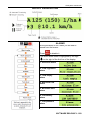
DISPLAY VISUALIZATION
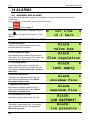
ALARMS
At the activation of one alarm you will hear a
sound from the buzzer.
Press
to disable it.
The active alarm state is highlighted by the sign
on the right of the first line of the display.
1. Valve box alarm
2. Flow regulation
alarm
3. Tank empty
alarm
4. Minimum flow
alarm
5. Maximum flow
alarm
6. Low battery
alarm
7. Low pressure
alarm
SOFTWARE RELEASE 1.1.3O
Cod. 985-0087 Rev. A2
21/02/2014