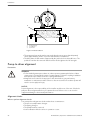
1
Installation, Operation
and Maintenance Manual
HL
Table of Contents
Table of Contents
Introduction and Safety..................................................................................................................3
Introduction..................................................................................................................................3
Safety.............................................................................................................................................3
Safety terminology and symbols........................................................................................... 3
Environmental safety...............................................................................................................4
User safety................................................................................................................................ 5
Product warranty......................................................................................................................... 6
Transportation and Storage.......................................................................................................... 7
Inspect the unit............................................................................................................................ 7
Transportation guidelines.......................................................................................................... 7
Check the trailer connection for the tow.............................................................................. 7
Disconnection from the towing vehicle................................................................................ 8
Fasten the unit..........................................................................................................................8
Lifting...................................................................................................................................... 10
Storage guidelines.................................................................................................................... 13
Short-term storage................................................................................................................ 13
Long-term storage................................................................................................................ 13
Product Description......................................................................................................................15
General description.................................................................................................................. 15
California proposition 65......................................................................................................15
Operational specifications....................................................................................................... 16
Nameplates................................................................................................................................16
Installation......................................................................................................................................18
Pre-Installation........................................................................................................................... 18
Pump location guidelines.....................................................................................................18
Piping checklists........................................................................................................................ 19
General piping checklist.......................................................................................................19
Suction-piping checklist....................................................................................................... 20
Discharge piping checklist...................................................................................................21
Final piping checklist............................................................................................................ 22
Permanent installation for skid mounted units......................................................................22
Prepare the skid.....................................................................................................................23
Requirements for foundation and anchor bolts................................................................ 23
Place the skid......................................................................................................................... 24
Fabricate the grout forms.....................................................................................................24
Pour the grout........................................................................................................................25
Pump-to-driver alignment........................................................................................................26
Alignment checks.................................................................................................................. 26
Alignment measurement guidelines.................................................................................. 27
Attach the dial indicators for alignment............................................................................. 27
Pump-to-driver alignment instructions...............................................................................28
Commissioning, Startup, Operation, and Shutdown...............................................................30
Preparation for startup............................................................................................................. 30
Operate the unit with the system condition of flooded suction......................................30
Bearing lubrication................................................................................................................31
Mechanical seal coolant....................................................................................................... 33
HL Installation, Operation and Maintenance Manual
1
Table of Contents
Start the pump........................................................................................................................... 34
Pump operation precautions................................................................................................... 35
Shut down the pump................................................................................................................ 35
Maintenance..................................................................................................................................36
Routine maintenance precautions.......................................................................................... 36
Daily maintenance.....................................................................................................................36
Engine maintenance............................................................................................................. 36
Pump maintenance............................................................................................................... 37
Air compressor maintenance...............................................................................................37
Vacuum pump maintenance................................................................................................37
Gearbox maintenance.......................................................................................................... 37
Ejector silencer maintenance...............................................................................................37
Towing maintenance................................................................................................................ 37
After the first 100 hours............................................................................................................ 38
Air compressor maintenance...............................................................................................38
250 hour maintenance..............................................................................................................38
Pump maintenance............................................................................................................... 38
Engine maintenance............................................................................................................. 38
Motor maintenance...............................................................................................................39
Air compressor maintenance...............................................................................................39
Vacuum pump maintenance................................................................................................39
500 hour maintenance..............................................................................................................40
Air compressor...................................................................................................................... 40
Vacuum pump maintenance................................................................................................40
1000 hour maintenance........................................................................................................... 40
Air compressor...................................................................................................................... 40
Vacuum pump maintenance................................................................................................40
Gearbox maintenance.......................................................................................................... 40
2000 hour maintenance........................................................................................................... 41
Air compressor...................................................................................................................... 41
5000 hour maintenance........................................................................................................... 41
Pump maintenance............................................................................................................... 41
Troubleshooting........................................................................................................................... 42
Troubleshooting precautions.................................................................................................. 42
Troubleshooting — Pump......................................................................................................... 42
Troubleshooting — Driver.........................................................................................................46
Troubleshooting — Trailer........................................................................................................ 46
Technical Reference..................................................................................................................... 49
Designations, sizes, and capacities.........................................................................................49
Coolants and lubricants............................................................................................................49
Torque values............................................................................................................................ 51
Belt tensioning...........................................................................................................................52
Force and deflection method.............................................................................................. 52
Belt tension values................................................................................................................ 52
Impeller to wear plate clearances........................................................................................... 53
2
HL Installation, Operation and Maintenance Manual
Introduction and Safety
Introduction and Safety
Introduction
Purpose of this manual
The purpose of this manual is to provide necessary information for:
• Installation
• Operation
• Maintenance
CAUTION:
Read this manual carefully before installing and using the product. Improper use of the
product can cause personal injury and damage to property, and may void the warranty.
NOTICE:
Save this manual for future reference, and keep it readily available at the location of the
unit.
Safety
WARNING:
• The operator must be aware of safety precautions to prevent physical injury.
• Any pressure-containing device can explode, rupture, or discharge its contents if it is
over-pressurized. Take all necessary measures to avoid over-pressurization.
• Operating, installing, or maintaining the unit in any way that is not covered in this
manual could cause death, serious personal injury, or damage to the equipment. This
includes any modification to the equipment or use of parts not provided by Xylem. If
there is a question regarding the intended use of the equipment, please contact a
Xylem representative before proceeding.
• Do not change the service application without the approval of an authorized Xylem
representative.
CAUTION:
You must observe the instructions contained in this manual. Failure to do so could result
in physical injury, damage, or delays.
Safety terminology and symbols
About safety messages
It is extremely important that you read, understand, and follow the safety messages and
regulations carefully before handling the product. They are published to help prevent
these hazards:
• Personal accidents and health problems
• Damage to the product
• Product malfunction
HL Installation, Operation and Maintenance Manual
3
Introduction and Safety
Hazard levels
Hazard level
Indication
DANGER:
A hazardous situation which, if not avoided, will result in
death or serious injury
WARNING:
A hazardous situation which, if not avoided, could result
in death or serious injury
CAUTION:
A hazardous situation which, if not avoided, could result
in minor or moderate injury
NOTICE:
• A potential situation which, if not avoided, could
result in undesirable conditions
• A practice not related to personal injury
Hazard categories
Hazard categories can either fall under hazard levels or let specific symbols replace the
ordinary hazard level symbols.
Electrical hazards are indicated by the following specific symbol:
Electrical Hazard:
These are examples of other categories that can occur. They fall under the ordinary
hazard levels and may use complementing symbols:
• Crush hazard
• Cutting hazard
• Arc flash hazard
Environmental safety
The work area
Always keep the station clean.
Waste and emissions regulations
Observe these safety regulations regarding waste and emissions:
• Appropriately dispose of all waste.
• Handle and dispose of the processed liquid in compliance with applicable
environmental regulations.
• Clean up all spills in accordance with safety and environmental procedures.
• Report all environmental emissions to the appropriate authorities.
WARNING:
Radiation Hazard. Do NOT send the product to Xylem if it has been exposed to any
nuclear radiation.
Electrical installation
For electrical installation recycling requirements, consult your local electric utility.
4
HL Installation, Operation and Maintenance Manual
Introduction and Safety
Recycling guidelines
Always follow local laws and regulations regarding recycling.
User safety
General safety rules
These safety rules apply:
• Always keep the work area clean.
• Pay attention to the risks presented by gas and vapors in the work area.
• Avoid all electrical dangers. Pay attention to the risks of electric shock or arc flash
hazards.
• Always bear in mind the risk of drowning, electrical accidents, and burn injuries.
Safety equipment
Use safety equipment according to the company regulations. Use this safety equipment
within the work area:
• Hard hat
• Safety goggles, preferably with side shields
• Protective shoes
• Protective gloves
• Gas mask
• Hearing protection
• First-aid kit
• Safety devices
NOTICE:
Never operate a unit unless safety devices are installed. Also see specific information
about safety devices in other chapters of this manual.
Electrical connections
Electrical connections must be made by certified electricians in compliance with all
international, national, state, and local regulations. For more information about
requirements, see sections dealing specifically with electrical connections.
Wash the skin and eyes
Follow these procedures for chemicals or hazardous fluids that have come into
contact with your eyes or your skin:
Condition
Action
Chemicals or hazardous fluids in
eyes
1.
2.
3.
Hold your eyelids apart forcibly with your fingers.
Rinse the eyes with eyewash or running water for at least 15 minutes.
Seek medical attention.
Chemicals or hazardous fluids on
skin
1.
2.
3.
Remove contaminated clothing.
Wash the skin with soap and water for at least 1 minute.
Seek medical attention, if necessary.
Hazardous liquids
The product is designed for use in liquids that can be hazardous to your health. Observe
these rules when you work with the product:
• Make sure that all personnel who work with biologically hazardous liquids are
vaccinated against diseases to which they may be exposed.
• Observe strict personal cleanliness.
HL Installation, Operation and Maintenance Manual
5
Introduction and Safety
Product warranty
Coverage
Xylem undertakes to remedy defects in products from Xylem under these conditions:
• The faults are due to defects in design, materials, or workmanship.
• The faults are reported to a local sales and service representative within the warranty
period.
• The product is used only under the conditions that are described in this manual.
• The monitoring equipment that is incorporated in the product is correctly connected
and in use.
• All service and repair work that is done by Xylem authorized personnel.
• Genuine Xylem parts are used.
• Only Ex-approved spare parts and accessories that are authorized by an Ex-approved
Xylem representative are used in Ex-approved products.
Limitations
The warranty does not cover defects that are caused by these situations:
• Deficient maintenance
• Improper installation
• Modifications or changes to the product and installation that are made without
consulting a Xylem authorized representative
• Incorrectly executed repair work
• Normal wear and tear
Xylem assumes no liability for these situations:
• Bodily injuries
• Material damages
• Economic losses
Warranty claim
Xylem products are high-quality products with expected reliable operation and long life.
However, should the need for a warranty claim arise, contact your local sales and service
representative.
6
HL Installation, Operation and Maintenance Manual
Transportation and Storage
Transportation and Storage
Inspect the unit
1. Remove packing materials from the product.
Dispose of all packing materials in accordance with local regulations.
2. Inspect the product to determine if any parts have been damaged or are missing.
3. If applicable, unfasten the product by removing any screws, bolts, or straps.
For your personal safety, be careful when you handle nails and straps.
4. Contact the local sales representative if there is any issue.
Transportation guidelines
Precautions
DANGER:
Disconnect and lock out electrical power before installing or servicing the unit.
WARNING:
• Stay clear of suspended loads.
• Observe accident prevention regulations in force.
Check the trailer connection for the tow
Read the trailer operation manual before connection of the trailer to the tow vehicle.
• Follow all of the highway safety laws that pertain to the tow vehicle and the trailer in
your region.
• Use the proper sized tow vehicle for the load of the trailer.
• Ensure the trailer is operational and maintenance steps are complete.
• After connecting the hitch assembly to the tow vehicle, check that the hitch assembly
is latched.
• Verify that the rear and tongue jacks are raised after the trailer is attached to the tow
vehicle.
3
OIL
TEMP
15
20
10
1
25
30
5
35
40
HOURS
AMPERS
2
4
HL Installation, Operation and Maintenance Manual
5
7
Transportation and Storage
1.
2.
3.
4.
5.
Tongue jack
Pintle hitch
Lift bail
Rear jack
Safety chains
Figure 1: Trailer parts
Disconnection from the towing vehicle
CAUTION:
Tip hazard. Make sure that the prop stands are lowered and locked in place before
disconnecting trailer.
Fasten the unit
• Secure the unit with chains. If the chains are not available, then substitute straps with
edge protectors.
Do not place straps or chains over the top of the unit.
• Inspect chains and straps for damage. If damaged, then discard and replace.
• Secure the unit using appropriate tie down points on the skid.
• If the skid does not contain D-rings and fork pockets, then place chains and straps
around mounting base and tie together at a common point.
• If the skid contains D-rings and fork pockets, then place chains and straps through
fork pockets and D-rings.
OIL
TEMP
15
20
10
25
30
5
35
40
HOURS
AMPERS
1
2
Choose either of the following:
1.
2.
Position A.
Position B.
Figure 2: Skid without D-rings and fork pockets
8
HL Installation, Operation and Maintenance Manual
Transportation and Storage
Figure 3: Skid with D-rings and fork pockets
OIL
TEMP
15
20
10
25
30
5
35
40
HOURS
AMPERS
Figure 4: Trailer
Figure 5: Large skid without D-rings and fork pockets
HL Installation, Operation and Maintenance Manual
9
Transportation and Storage
Figure 6: Critically silenced enclosure
Lifting
WARNING:
Crush Hazard.
• Always lift the unit by its designated lifting points.
• Use suitable lifting equipment and ensure that the product is properly harnessed.
• Wear personal protective equipment.
• Stay clear of cables and suspended loads.
Lifting equipment and tackle should always be inspected before starting work.
Requirements for lifting
WARNING:
Lift and handle the product carefully, using suitable lifting equipment.
• The lifting equipment must be in good condition and operated by authorized
personnel.
• The lifting equipment must have the lifting capacity for the complete weight of the
assembly and its remaining pumped liquid.
• When a crane is used, the minimum height between the lifting hook and the ground
must be sufficient to lift the pump straight up and down.
Lift the unit using a crane
1. Check that the site where the unit is placed has a clean and level surface. Stones and
other debris damage the bottom structure of the unit.
2. If the unit was secured to a pallet, flatbed or other surface, then cut the transportation
straps.
3. If the unit has a single lift point, then connect the crane hook directly to the lift bail or
use a shackle.
If the unit is an enclosure, then only lift from the single point lifting bail and not from
any installed eye bolts.
4. If the unit has multiple lifting points, then fasten a suitable lifting strap or sling to the
available lifting bolts. To reduce damage to the engine and the pump components,
use a spreader bar.
5. Lift the unit using the proper lifting equipment.
6. Place the unit on firm, level ground.
10
HL Installation, Operation and Maintenance Manual
Transportation and Storage
OIL
TEMP
15
20
10
25
30
5
35
40
HOURS
AMPERS
Figure 7: Single lift point skid
Figure 8: Multiple lift point skid
Figure 9: Single point enclosure
Lift the pump using a crane
• Use only lifting equipment of suitable capacity for the size and weight of the lifted
equipment.
• The equipment must always be lifted using safe working practices and in accordance
with any local and national guidelines or statutes.
• The following figures show examples of lifting the pump without being attached to
the driver or base.
HL Installation, Operation and Maintenance Manual
11
Transportation and Storage
MAX
Figure 10: Lift a motor adaptor unit
Figure 11: Lift a bearing bracket unit
Lift the unit using a forklift
Lift the pump from either side with the forklift.
12
HL Installation, Operation and Maintenance Manual
Transportation and Storage
1. Check that the site where the pump is placed has a clean and level surface. Stones
and other debris damage the bottom structure of the pump.
2. If the pump was secured to a pallet, flatbed or other surface, then cut the
transportation straps.
3. Align the forklift prongs with the forklift holes in the bottom of the pump base.
4. Insert the forklift prongs into the forklift holes.
5. Lift the pump and move it to its new position.
6. Place the pump upright on a rigid horizontal surface so that it cannot fall over.
1
1.
Fork pockets
Figure 12: Fork pocket location
Storage guidelines
Storage location
The product must be stored in a covered and dry location free from heat, dirt, and
vibrations.
NOTICE:
• Protect the product against humidity, heat sources, and mechanical damage.
• Do not place heavy weights on the packed product.
Freezing precautions
NOTICE:
Do not expose an idle pump to freezing conditions. Drain all liquid that is inside the pump
and connected pipes. Failure to do so can cause liquid to freeze and damage the pump.
Short-term storage
Refer to the pump end and the drive unit maintenance manuals for detailed storage
instructions.
• Empty the pump of all product and clean surfaces of dirt, debris, oil, fuel, and
associated matter.
• Remove the front cover and coat the front of the wear plate and the impeller with an
appropriate rust inhibitor.
• Coat any unpainted, machined surfaces that are subjected to rust and corrosion.
If the pump is stored outside and subject to weather, then cover the pump and the engine
with a waterproof tarpaulin.
Long-term storage
• Perform all of the steps that are listed in the short-term storage section.
• Store the unit in a covered and dry location.
• Store the unit in a location free from heat, dirt, and vibrations.
HL Installation, Operation and Maintenance Manual
13
Transportation and Storage
• If an engine drives the pump, then perform the following steps:
a) Replace the oil and the oil filter.
b) Service the air cleaner.
c) Drain the fuel tank and add an inhibitor.
d) Add an inhibitor to the crank case.
e) Disconnect the air intake.
f) Disconnect and remove the battery.
g) Remove the belts.
h) Coat all machined surfaces on the engine with a rust inhibitor.
• Treat bearings and machined surfaces on the unit so that they are well preserved.
14
HL Installation, Operation and Maintenance Manual
Product Description
Product Description
General description
Materials
The pump is made of a combination of the following materials:
• Iron
• Steel
• Stainless steel
• Aluminium
Pump drive mounting method
The pump has three different methods to mount it to its driver:
• Close-coupled
• Long-coupled (shaft-to-shaft)
• SAE (for engine driven pumps)
Main parts
This table describes the main parts of the pump.
Part
Description
Pump impeller
An open impeller that is mounted to a shaft with one of the following methods:
• Threaded to the shaft and secured with a screw and a washer
• A spline and secured with a screw and an impeller washer
Pump casing
The pump casing is
• known as a volute
• equipped with replaceable wear plates
Driver
The pump is driven by one of the following:
• Diesel engine
• Electric motor
Base
The unit is mounted to one of the following:
• Skidbase
• Highway trailer
• Acoustic enclosure
• Site trolley
Suction and discharge connections
The suction side and discharge side of the pump have different kinds of connections
depending on the size of the pump. The smaller connection sizes are threaded onto the
pump. The larger connection sizes are flange mounted.
California proposition 65
WARNING:
California Proposition 65 warning! This product contains chemicals known to the state of
California to cause cancer and birth defects or other reproductive harm.
HL Installation, Operation and Maintenance Manual
15
Product Description
Operational specifications
Liquid characteristics
This table describes the liquid characteristics of the pump.
Parameter
Value
Maximum liquid temperature
80 ˚C (176 ˚F)
Consult your local Xylem representative for operation that
exceeds this temperature.
Pressure, solids handling and head
This table specifies the working and suction pressures, soft solids handling and head of
each pump model.
Model
Maximum pressure
Maximum suction pressure Maximum soft solids
handling
HL80M
9.2 bar (133 psi)
6.0 bar (87 psi)
25 mm (1.0 in)
HL100M
11.4 bar (165 psi)
6.0 bar (87 psi)
35 mm (1.4 in)
HL110M
18.3 bar (265 psi)
6.0 bar (87 psi)
20 mm (0.8 in)
HL125M
13.5 bar (196 psi)
6.0 bar (87 psi)
35 mm (1.4 in)
HL130M
18.8 bar (273 psi)
6.0 bar (87 psi)
22 mm (0.9 in)
HL150M
15.1 bar (219 psi)
6.0 bar (87 psi)
35 mm (1.4 in)
HL160M
18.5 bar (268 psi)
6.0 bar (87 psi)
35 mm (1.4 in)
HL200M
11.6 bar (168 psi)
6.0 bar (87 psi)
38 mm (1.5 in)
HL225M
11.3 bar (164 psi)
6.0 bar (87 psi)
65 mm (2.6 in)
HL250M
12.1 bar (175 psi)
6.0 bar (87 psi)
65 mm (2.6 in)
HL260M
14.4 bar (209 psi)
6.0 bar (87 psi)
50 mm (2.0 in)
Flanges and connections
This table describes the possible combinations of the flanges and the connections of the
pump.
Model
Suction side
Discharge size
HL80M
100 mm (4 in) flange
80 mm (3 in) flange
HL100M
100 mm (4 in) flange
100 mm (4 in) flange
HL110M
100 mm (4 in) flange
80 mm (3 in) flange
HL125M
150 mm (6 in) flange
100 mm (4 in) flange
HL130M
150 mm (6 in) flange
100 mm (4 in) flange
HL150M
150 mm (6 in) flange
150 mm (6 in) flange
HL160M
200 mm (8 in) flange
150 mm (6 in) flange
HL200M
200 mm (8 in) flange
150 mm (6 in) flange
HL225M
250 mm (10 in) flange
200 mm (8 in) flange
HL250M
300 mm (12 in) flange
250 mm (10 in) flange
HL260M
250 mm (10 in) flange
250 mm (10 in) flange
Nameplates
Usage
These numbers located on the nameplate must be quoted in any inquiry for spares or
service.
16
HL Installation, Operation and Maintenance Manual
Product Description
Fields and information
Every pump unit has a nameplate similar to the one shown in the illustration.
1.
2.
3.
4.
5.
6.
Pump model
Year of order
Order number
Unit number within order
Xylem reference number
Pressure and vacuum tested
Figure 13: Example of a pump nameplate
HL Installation, Operation and Maintenance Manual
17
Installation
Installation
Pre-Installation
Pump location guidelines
WARNING:
Fire hazard. Overloaded electrical circuits can cause components to overheat. Make sure
to use appropriate circuit protection.
WARNING:
Assembled units and their components are heavy. Failure to properly lift and support this
equipment can result in serious physical injury and/or equipment damage. Lift equipment
only at the specifically identified lifting points. Lifting devices such as eyebolts, slings, and
spreaders must be rated, selected, and used for the entire load being lifted.
Guideline
Explanation/comment
Make sure that the space around the pump is sufficient.
This facilitates ventilation, inspection, maintenance, and
service.
If you require lifting equipment such as a hoist or tackle, This makes it easier to properly use the lifting equipment
make sure that there is enough space above the pump. and safely remove and relocate the components to a safe
location.
Protect the unit from weather and water damage due to
rain, flooding, and freezing temperatures.
This is applicable if nothing else is specified.
Do not install and operate the equipment in closed
systems unless the system is constructed with properlysized safety devices and control devices.
Acceptable devices:
• Pressure relief valves
• Pressure controls
• Temperature controls
• Flow controls
If the system does not include these devices, consult the
engineer or architect in charge before you operate the
pump.
Take into consideration the occurrence of unwanted
noise and vibration.
—
Make sure that the pump location is on solid, level
ground.
This ensures that the pump remains stable and balanced
while in operation.
Check fluid levels
• Ensure that the following fluids are at the correct levels before starting the pump:
• Engine oil
• Engine coolant
• Pump mechanical seal coolant
• Compressor oil, if not connected to a diesel engine
• Engine fuel
• Gearbox oil
Refer to component-specific manuals for location of level indicators and the required
fluids.
18
HL Installation, Operation and Maintenance Manual
Installation
Verify general operation
WARNING:
Compressed Gas Hazard. Never apply a pressure to any cavity or chamber in the product
to test for leakage. Pressurized air may cause parts to be propelled with force.
Overpressurization can cause structural failure.
To verify general operation before installing the equipment, pull vacuum with a vacuum
pad.
1. Close the drain valve on the volute and the discharge non-return valve.
2. Start the driver and allow it to warm up while idling.
3. Position the vacuum pad on the pump suction flange. Make sure the pad gasket seats
firmly around the edge.
4. Raise the driver speed to the normal operating speed. See Designations, sizes, and
capacities (page 49) for operating speeds.
5. Record the reading on the vacuum pad gauge.
6. Verify that the gauge reads 20 - 25 in of mercury (0.70 – 0.75 bar). If not, then begin to
troubleshoot the unit.
7. To release the vacuum pad, open the drain valves.
Check the application
• Review the system curve information and ensure that the correct pipe size was
chosen.
• Ensure that the suction and discharge requirements for the application have not
changed.
For example: The application was originally specified as a suction lift and horizontal
open discharge, but now is a flooded suction, horizontal open discharge.
Piping checklists
General piping checklist
Precautions
CAUTION:
• Never draw piping into place by using force at the flanged connections of the pump.
This can impose dangerous strains on the unit and cause misalignment between the
pump and driver. Pipe strain adversely affects the operation of the pump, which
results in physical injury and damage to the equipment.
• Vary the capacity with the regulating valve in the discharge line. Never throttle the
flow from the suction side. This action can result in decreased performance,
unexpected heat generation, and equipment damage.
• Use pipes suited to the maximum working pressure of the pump. Failure to do so can
cause the system to rupture, with the risk of injury.
Checklist
Check
Explanation/comment
Checked
Check that all piping is supported
This helps to prevent:
independently of, and lined up
• Strain on the pump
naturally with, the pump connection.
• Misalignment between the pump and the drive unit
• Wear on the pump bearings, seal, and shafting
See Example section for illustrations of pipe supports.
Check that only necessary fittings are This helps to minimize friction losses.
used.
HL Installation, Operation and Maintenance Manual
19
Installation
Check
Explanation/comment
Make sure that all the piping joints
and fittings are airtight.
This prevents air from entering the piping system or leaks that
occur during operation.
Checked
If the pump handles corrosive fluids, This protects the employees and operators.
make sure that the piping allows you
to flush out the liquid before you
remove the pump.
If the pump handles liquids at
elevated temperatures, make sure
that the expansion loops and joints
are properly installed.
This helps to prevent misalignment due to thermal expansion
of the piping.
If the pump handles corrosive
—
liquids, make sure that the piping is
correctly rated for the application.
Example: Pipe supports
Suction-piping checklist
Performance curve reference
CAUTION:
Vary the capacity with the regulating valve in the discharge line. Never throttle the flow
from the suction side. This action can result in decreased performance, unexpected heat
generation, and equipment damage.
Net positive suction head available (NPSHA) must always exceed NPSH required (NPSHR)
as shown on the published performance curve of the pump.
Suction-piping checks
Check
Explanation/comment
Checked
Check that the distance between the inlet flange of the pump and the This minimizes the risk of
closest elbow is at least four pipe diameters.
cavitation in the suction inlet of the
pump due to turbulence.
Check that elbows in general do not have sharp bends.
20
—
HL Installation, Operation and Maintenance Manual
Installation
Check
Explanation/comment
Checked
Check that the eccentric reducer at the suction flange of the pump has —
the following properties:
• Sloping side down
• Horizontal side at the top
If suction strainers or suction bells are used, check that they are at
least three times the area of the suction piping.
Suction strainers help to prevent
clogging.
If more than one pump operates from the same liquid source, check
that separate suction-piping lines are used for each pump.
This recommendation helps you to
achieve a higher pump
performance.
If necessary, make sure that the suction piping includes a drain valve —
and that it is correctly installed.
Liquid source below the pump
Check
Explanation/comment
Checked
Make sure that the suction piping is free from air pockets.
This helps to prevent the occurrence of air
and cavitation in the pump inlet.
Check that the suction piping slopes upwards from the liquid
source to the pump inlet.
—
Check that all joints are air-tight.
—
Liquid source above the pump
Check
Explanation/comment
Checked
Check that an isolation valve is installed in the
suction piping at a distance of at least two times the
pipe diameter from the suction inlet.
This permits you to close the line during pump
inspection and maintenance.
Do not use the isolation valve to throttle the pump.
Throttling can cause these problems:
• Loss of priming
• Excessive temperatures
• Damage to the pump
• Voiding the warranty
Make sure that the suction piping is free from air
pockets.
This helps to prevent the occurrence of air and
cavitation in the pump inlet.
Check that the piping is level or slopes downward
from the liquid source.
—
Make sure that the size of the entrance from the
supply is one or two sizes larger than the suction
pipe.
—
Make sure that the suction piping is adequately
submerged below the surface of the liquid source.
This prevents air from entering the pump through a
suction vortex.
Discharge piping checklist
Checklist
Check
Explanation/comment
Check that an isolation valve is, when
possible, installed in the discharge line.
The isolation valve is required for:
• Regulation of flow
• Inspection and maintenance of the pump
• Regulation of pressure
HL Installation, Operation and Maintenance Manual
Checked
21
Installation
Check
Explanation/comment
Checked
Check that a check valve is installed in the The location between the isolation valve and the pump
discharge line, between the isolation valve allows inspection of the check valve.
and the pump discharge outlet.
The check valve facilitates priming. It is also used to
prevent damage to the pump and seal due to the back
flow through the pump, when the drive unit is shut off.
If increasers are used, check that they are
installed between the pump and the
isolation valve.
—
If quick-closing valves are installed in the This protects the pump from surges and water hammer.
system, check that cushioning devices are
used.
Check that a secondary check valve is
fitted.
A secondary check valve is required for:
• Operation within a closed system
• High head applications
• Suction lifts greater than 23 ft (7 m) with a low
slung discharge line
Final piping checklist
Check
Explanation/comment
If electric motor driven, check that the shaft
rotates smoothly.
Ensure that the power is disconnected.
Rotate the shaft by hand. Make sure that there is no
rubbing that leads to excess heat generation or sparks.
To make sure that pipe strain has not caused
any misalignment, recheck the alignment.
If pipe strain exists, then correct the piping.
Checked
Permanent installation for skid mounted units
Installation stages
After selecting a location and installing the concrete, the permanent installation will
consist of the following:
• Preparation of the skid
• Installation of the anchor bolts
• Placement of the skid
• Fabrication of the grout forms
• Pouring of the grout
4
3
2
1
22
5
HL Installation, Operation and Maintenance Manual
Installation
1.
2.
3.
4.
5.
Forms
Anchor bolts
Epoxy grout
Motor
Concrete
Figure 14: Permanent installation components
Prepare the skid
Required tools and equipment:
• Hoist equipment
• Hand tools
• Sandblaster
1. Disconnect the coupling between the motor and the pump. Remove the motor and
the pump from the skid.
2. Turn the skid base upside down. To remove any paint, rust, scale, or debris that may
prevent adhesion, sandblast all of the surfaces that will be in contact with the grout.
3. Turn the skid right side up. Coat the jack bolts with anti-sieze lubricant and install. The
jack bolts will extend approximately 2-1/2" from the bottom of the skid.
Requirements for foundation and anchor bolts
Foundation
• The foundation must be able to absorb any type of vibration and form a permanent,
rigid support for the unit.
• The foundation must be poured on a solid footing using a one-three-five mix that is
thick enough to support the pump unit.
Anchor bolts
• The location and size of the anchor bolt holes are shown on the outline assembly
drawing for the pump unit.
• Each bolt must be installed with a pipe sleeve around it for adjustment. The inside
sleeve diameter must be 2.5 to 3 times the diameter of the bolt.
• The bolt must be held in position during the installation process.
• The area between the bolt and sleeve must be free of concrete.
• The anchor bolt must be long enough to project through the nut 0.25 in or 6.4 mm
after allowance has been made for:
• Grout
• Height of the jack bolts
• Skid
• Anchor bolt nut
HL Installation, Operation and Maintenance Manual
23
Installation
2
1
3
4
5
6
1.
2.
3.
4.
5.
6.
Vent hole plug
Air release vent
Jack bolt
Nut welded to the top of the skid
Pad
Anchor bolt
Figure 15: Installation of the anchor bolts
Place the skid
1. Use jack bolts to level skid base across the motor mounting location and pump base
mounting location.
Mounting surfaces elevations should be within 1/16" as measured across the
diagonals.
2. Replace the motor on the base plate of the skid so that the motor mounting holes are
centered on the base plate motor mount holes.
3. Adjust the jack bolts on the skid base till the suction flange is plumb with the horizon.
Place the pump on the skid base with 0.075" of shims under all six mounting holes.
4. Align the motor and pump shafts in the vertical plane to a tolerance of 3 mills offset
and 5 mills gap over a 10" coupling by shimming under the motor.
5. The motor holes are rechecked for being concentric with the base plate holes.
This gives maximum potential for final alignment. The pump and motor shafts are then
aligned horizontally to a tolerance of 3 mills offset and 5 mills gap over the coupling
by moving the pump to the motor.
6. Place a machinist’s level on the suction flange of the pump.
7. Tighten the anchor bolt nuts so that the base is tight to the concrete slab.
Fabricate the grout forms
Required materials:
• Hand tools
• 2” x 4” studs
• 1/2” CDX Plywood
24
HL Installation, Operation and Maintenance Manual
Installation
1. Install lumber form work around the perimeter of the skid. Form work faces in contract
with grout shall be coated with a form release oil or other similar .
2. Form work should be secured to the concrete slab with bolts and drop in anchors to
prevent movement while the grout is being placed.
3. All forms should butt tightly against the perimeter of the steel skid base to prevent
grout from escaping during the placement.
1
2
1.
2.
1/2” Plywood
2” x 4” Studs
Figure 16: Grout form details
Pour the grout
Required materials:
• Epoxy grout
• Hand tools
1. Mix epoxy grout components as per the manufacturer’s instructions.
2. Pour grout:
a) Pour until the bottom flange is covered.
b) Trowel off excess where needed and allow epoxy grout to stand until firm.
c) Pour until the top flange is covered.
d) Trowel off excess where needed and allow epoxy grout to stand until firm.
HL Installation, Operation and Maintenance Manual
25
Installation
2
1
3
1.
2.
3.
Bottom flange
Top flange
Concrete
Figure 17: Grout locations
• The temporary form work may be removed after the epoxy grout has adequately
cured, approximately 24 hrs. or per the manufacturer’s instructions.
• The base plate should remain supported by the jack bolts for at least 48 hours. The
jack bolts can then be removed and the anchor bolts tightened to full strength.
Pump-to-driver alignment
Precautions
WARNING:
• Follow shaft alignment procedures in order to prevent catastrophic failure of drive
components or unintended contact of rotating parts. Follow the coupling installation
and operation procedures from the coupling manufacturer.
• Always disconnect and lock out power to the driver before you perform any
installation or maintenance tasks. Failure to disconnect and lock out driver power will
result in serious physical injury.
NOTICE:
Proper alignment is the responsibility of the installer and the user of the unit. Check the
pump-to-driver alignment before you operate the unit. Failure to do so can result in
equipment damage or decreased performance.
Alignment checks
When to perform alignment checks
You must perform alignment checks under these circumstances:
• The process temperature changes.
• The piping changes.
• The pump has been serviced.
• Severe vibration while the unit is in operation occurs.
26
HL Installation, Operation and Maintenance Manual
Installation
• The pump has been removed.
• The driver has been moved.
Pumps that are close-coupled to a diesel engine do not require alignment.
Types of misalignment
Type of misalignment
Description
Angular misalignment
Shafts have an axis concentric at the intersection but not parallel.
Parallel offset misalignment
Shafts have an axis parallel but offset.
Check and correct angular misalignment before correcting parallel misalignment.
Types of alignment checks
Type of check
When it is used
Initial alignment (cold alignment)
check
Prior to operation when the pump and the driver are at ambient
temperature.
Final alignment (hot alignment)
check
After operation when the pump and the driver are at operating temperature.
Initial alignment (cold alignment) checks
When
Why
After you connect the piping
This ensures that pipe strains have not altered the alignment.
If changes have occurred, you must alter the piping to remove pipe strains on
the pump connections.
Final alignment (hot alignment) checks
When
Why
After the first run
This ensures correct alignment when both the pump and the driver are at
operating temperature.
Periodically
This follows the plant operating procedures.
Alignment measurement guidelines
Guideline
Explanation
Rotate the pump coupling half and the driver coupling half together
so that the indicator rods have contact with the same points on the
driver coupling half.
This prevents incorrect measurement.
Move or shim only the driver in order to make adjustments.
This prevents strain on the piping
installations.
Make sure that the hold-down bolts for the driver feet are tight when
you take indicator measurements.
This keeps the driver stationary since
movement causes incorrect measurement.
Make sure that the hold-down bolts for the driver feet are loose before This makes it possible to move the driver
you make alignment corrections.
when you make alignment corrections.
Check the alignment again after any mechanical adjustments.
This corrects any misalignments that an
adjustment may have caused.
Attach the dial indicators for alignment
You must have two dial indicators in order to complete this procedure.
1. Attach two dial indicators on the pump coupling half (X):
a) Attach one indicator (P) so that the indicator rod comes into contact with the
perimeter of the driver coupling half (Y).
HL Installation, Operation and Maintenance Manual
27
Installation
This indicator is used to measure parallel misalignment.
b) Attach the other indicator (A) so that the indicator rod comes into contact with the
inner end of the driver coupling half.
This indicator is used to measure angular misalignment.
P
A
Y
X
2. Rotate the pump coupling half (X) in order to check that the indicators are in contact
with the driver coupling half (Y) but do not bottom out.
3. Adjust the indicators if necessary.
Pump-to-driver alignment instructions
Perform parallel alignment for a horizontal correction
Before you start this procedure, make sure that the dial indicators are properly attached
for measurement.
A unit is in parallel alignment when the parallel indicator (P) does not vary by more than
the values given on the included coupling drawing as measured at four points 90° apart at
the operating temperature.
1. Set the parallel alignment indicator (P) to zero on the left side of the driver coupling
half (Y), 90° from the top-center position (9 o’clock).
2. Rotate the indicator through the top-center position to the right side, 180° from the
start position (3 o’clock).
3. Record the indicator reading.
Reading value
Driver coupling half (Y) placement
Negative
To the left of the pump coupling half (X).
Positive
To the right of the pump coupling half (X).
4. Slide the driver carefully in the appropriate direction.
NOTICE:
Make sure to slide the driver evenly. Failure to do so can negatively affect horizontal
angular correction.
28
HL Installation, Operation and Maintenance Manual
Installation
Figure 18: Example of incorrect parallel alignment
5. Repeat the previous steps until the permitted reading value is achieved.
NOTICE:
Use the specified permitted reading values unless specified otherwise by the coupling
manufacturer. Failure to do so may result in reducing the reliability of the pump.
Perform parallel alignment for a vertical correction
Before you start this procedure, make sure that the dial indicators are properly attached
for measurement.
A unit is in parallel alignment when the parallel indicator (P) does not vary by more than
the values given on the included coupling drawing as measured at four points 90° apart at
the operating temperature.
1. Set the parallel alignment indicator (P) to zero at the top-center position (12 o’clock) of
the driver coupling half (Y).
2. Rotate the indicator to the bottom-center position (6 o’clock).
3. Record the indicator reading.
Example illustration given in previous section.
Condition
Action
Negative reading value: The pump coupling half (X) is Remove shims of a thickness equal to half of the
lower than the driver coupling half (Y).
indicator reading value under each driver foot.
Positive reading value: The pump coupling half (X) is Add shims of a thickness equal to half of the indicator
higher than the driver coupling half (Y).
reading value to each driver foot.
NOTICE:
You must use an equal amount of shims with each driver foot to prevent
misalignment. Failure to do so can result in equipment damage or decreased
performance.
4. Repeat the previous steps until the permitted reading value is achieved.
NOTICE:
Use the specified permitted reading values unless specified otherwise by the coupling
manufacturer. Failure to do so may result in reducing the reliability of the pump.
HL Installation, Operation and Maintenance Manual
29
Commissioning, Startup, Operation, and Shutdown
Commissioning, Startup, Operation,
and Shutdown
Preparation for startup
DANGER:
Never put your hand into the pump housing.
WARNING:
Fire hazard. Overloaded electrical circuits can cause components to overheat. Make sure
to use appropriate circuit protection.
WARNING:
• Failure to follow these precautions before you start the unit will lead to serious
personal injury and equipment failure.
• Explosion hazard. Do not short battery terminals together or damage the battery.
• Always disconnect and lock out power to the driver before you perform any
installation or maintenance tasks. Failure to disconnect and lock out driver power will
result in serious physical injury.
• Operating the pump in reverse rotation can result in the contact of metal parts, heat
generation, and breach of containment.
• Do not operate the unit if the fuel tank has been damaged.
• Do not operate the unit in an area where explosive gases are present.
• Always operate the unit in a well ventilated area, preferably outdoors.
• Do not refuel the engine while it is running.
• Always wipe up spilled fuel and oil before operating the unit.
• Drain oil and moisture residue daily or after each use from the air receiver located on
the compressor.
• Always inspect the conductors on electric motors before operation.
• The unit and all components must be properly maintained.
• Do not smoke while refilling the engine.
• Do not refill an engine near open flames or sparks.
NOTICE:
• Verify the driver settings before you start any pump.
You must follow these precautions before you start the pump:
• Familiarize yourself with the controls of the driver.
• Flush and clear the system thoroughly to remove dirt or debris in the pipe system in
order to prevent premature failure at initial startup.
• Check all fluid levels.
Operate the unit with the system condition of flooded suction
Operation of a pump with the liquid source located above the pump is known as Flooded
Suction. To operate this pump with the system condition of flooded suction, you must
follow these steps.
30
HL Installation, Operation and Maintenance Manual
Commissioning, Startup, Operation, and Shutdown
WARNING:
Always disconnect and lock out power to the driver before you perform any installation or
maintenance tasks. Failure to disconnect and lock out driver power will result in serious
physical injury.
1. Isolate the driver and ensure that the unit cannot be started.
2. Disconnect the air line from the priming tower.
3. Select the following step, depending on a compressor unit or vacuum pump unit.
• Compressor units: disconnect the compressor belt drive.
• Vacuum pump units: disconnect the vacuum belt drive.
4. Select the following step, depending on a compressor unit or vacuum pump unit.
• Compressor units: remove the complete ejector housing and replace with a plain
blanking plate.
• Vacuum pump units: remove the complete priming tower and replace with a plain
blanking plate.
Blanking plates are available from your local Xylem representative.
5. Ensure that the blanking plate has a leak free seal to the pump.
6. Remove the means of isolation from the driver.
7. To start the pump with the system condition of flooded suction:
a) Close the inlet valve.
b) Start the driver.
c) Open the inlet valve.
8. To stop the pump with the system condition of flooded suction:
a) Stop the driver.
b) Close the inlet valve.
Example: disconnection of a compressor
Example: disconnection of a vacuum pump
3
3
4
4
Bearing lubrication
WARNING:
Make sure to properly lubricate the bearings. Failure to do so can result in excess heat
generation, sparks, and premature failure.
HL Installation, Operation and Maintenance Manual
31
Commissioning, Startup, Operation, and Shutdown
NOTICE:
Be certain to check the greasing on a pump that has been out of service for a long period
of time and re-grease if necessary.
• For recommended lubricants, refer to Technical Reference (page 49).
Locations of lubrication points (X)
X
X
X
X
X
X
Figure 19: Locations on smaller bearing brackets
X
X
Figure 20: Locations on larger bearing brackets
32
HL Installation, Operation and Maintenance Manual
Commissioning, Startup, Operation, and Shutdown
Mechanical seal coolant
All pumps are fitted with mechanical seals that require a coolant.
NOTICE:
• Some pumps are not supplied with a seal coolant.
• Seal oil must be changed at the first sign of sludging.
• Seal failure caused by the lack of correct and sufficient coolant will void the warranty.
• The level of coolant varies due to the operating conditions of the pump. A slight loss
of coolant under high suction lift conditions or slight emulsification of oil under low
conditions is normal.
• Check level of coolant in the seal housing daily.
For required coolants and quantities, refer to Technical Reference (page 49).
Fill (1) and drain plug (2) locations
1
1
2
2
1
1
2
2
Figure 21: Locations on smaller pumps
HL Installation, Operation and Maintenance Manual
33
Commissioning, Startup, Operation, and Shutdown
1
2
Figure 22: Locations on larger pumps
Start the pump
CAUTION:
• Observe the pump for vibration levels, bearing temperature, and excessive noise. If
normal levels are exceeded, shut down the pump and resolve the issue.
• Monitor all gauges to ensure that the pump is running at or near rating and that the
suction screen (when used) is not clogged.
• If the unit is driven by a diesel engine, refer to the engine manual.
• If the unit is driven by an electric motor, refer to the relevant control requirements.
1. If fitted, open the suction valve.
2. If fitted and depending on the system condition, fully close or partially open the
discharge valve.
3. Start the driver. The air compressor or vacuum pump will start to prime the pump.
4. If fitted, open the discharge valve until the pump reaches the desired flow.
5. Check the pressure gauge to ensure the pump is operating at the correct discharge
pressure.
6. If the pump fails to reach the correct pressure:
a) Stop the driver.
b) Begin to troubleshoot the unit.
34
HL Installation, Operation and Maintenance Manual
Commissioning, Startup, Operation, and Shutdown
Pump operation precautions
General considerations
CAUTION:
• Vary the capacity with the regulating valve in the discharge line. Never throttle the
flow from the suction side since this can result in decreased performance, unexpected
heat generation, and equipment damage.
• Do not overload the driver. Driver overload can result in unexpected heat generation
and equipment damage. The driver can overload in these circumstances:
• The specific gravity of the pumped fluid is greater than expected.
• The pumped fluid exceeds the rated flow rate.
• Make sure to operate the pump at or near the rated conditions. Failure to do so can
result in pump damage from cavitation or recirculation.
• Never operate a pump without a properly installed coupling guard. Personal injury
will occur if you run the pump without a coupling guard.
• Burn hazard. During operation various surfaces on the unit will become hot. To avoid
burn injury, use heat protective gloves.
Operation at reduced capacity
WARNING:
Never operate any pumping system with a blocked suction and discharge. Operation,
even for a brief period under these conditions, can cause confined pumped fluid to
overheat, which results in a violent explosion. You must take all necessary measures to
avoid this condition.
NOTICE:
• Avoid increased radial load. Failure to do so can cause stress on the shaft and
bearings.
• Avoid heat build-up. Failure to do so can cause rotating parts to score or seize.
• Avoid cavitation. Failure to do so can cause damage to the internal surfaces of the
pump.
Operation under freezing conditions
NOTICE:
Do not expose an idle pump to freezing conditions. Drain all liquid that is inside the pump
and connected pipes. Failure to do so can cause liquid to freeze and damage the pump.
Shut down the pump
1. Slowly run the driver down to stop.
2. Shut down and lock the driver to prevent accidental rotation.
HL Installation, Operation and Maintenance Manual
35
Maintenance
Maintenance
Routine maintenance precautions
DANGER:
Electrical hazard sufficient to kill. Always disconnect and lock out the power before you
service the unit.
WARNING:
Fire hazard. Overloaded electrical circuits can cause components to overheat. Make sure
to use appropriate circuit protection.
WARNING:
• Pressurized device. Make sure that the internal pressure is relieved before you
continue.
• Compressed Gas Hazard. Never apply a pressure to any cavity or chamber in the
product to test for leakage. Pressurized air may cause parts to be propelled with force.
Overpressurization can cause structural failure.
• Make sure that the pump is isolated from the system and that pressure is relieved
before you disassemble the pump, remove plugs, open vent or drain valves, or
disconnect the piping.
• Maintenance and service must be performed by skilled and qualified personnel only.
• Always disconnect and lock out power to the driver before you perform any
installation or maintenance tasks. Failure to disconnect and lock out driver power will
result in serious physical injury.
• Do not smoke while refilling the engine.
• Do not refill an engine near open flames or sparks.
CAUTION:
• Allow all system and pump components to cool before you handle them to prevent
physical injury.
• A worn pump can have components that have very sharp edges. Wear protective
gloves.
• Wear protective clothing. The edges of the parts can be sharp.
• Read all operation and maintenance manuals supplied with the pump assembly.
• Some engine manufacturers require a break-in period before the 250 hour service.
Refer to the engine operation and maintenance manual for the details of the break-in
period.
Daily maintenance
Engine maintenance
Perform the following on a daily basis before starting or operating the engine.
• Check the engine oil level. Verify that the level indication on the measuring stick is
within the crosshatch pattern or at the “FULL” mark. If the oil level is low, then
replenish with the correct engine oil.
36
HL Installation, Operation and Maintenance Manual
Maintenance
Refer to the engine manufacturer’s manual for the correct engine oil.
• Check the diesel fuel for the presence of water. If water is detected, then drain and
clean the fuel tank. Otherwise, check the fuel level and replenish as necessary.
• Check the radiator coolant level.
Pump maintenance
• Check the coolant level in the mechanical seal. Replenish as necessary.
For required mechanical seal coolant, refer to Technical Reference (page 49).
• Check the position of the volute and the discharge non-return drain valves. Verify that
the valves are closed before operation.
Air compressor maintenance
• Check for any unusual noise or vibration.
• Conduct a visual inspection and ensure that all guards are in place.
• Check all pressurized components for rust, cracks, or leaks.
• Check for lubricant leaks.
• Check for the correct actuation of the pressure relief valve on the compressor. Verify
that the valve easily springs back into the original position when released.
• For air compressors utilizing an integral oil sump:
a) Maintain the oil level between the high and low marks on the dipstick.
b) Check the oil for any contamination. If contaminated, then drain and refill the
compressor with an appropriate oil.
For recommended air compressor oil, refer to Technical Reference (page 49).
If any problems are discovered, then discontinue use of the equipment and consult your
local Xylem representative.
Vacuum pump maintenance
• Check the oil level.
• Check for the feed of oil through the sight glass.
• Drain the moisture trap.
Gearbox maintenance
If the unit contains a gearbox, then perform the following on a daily basis before starting
the unit.
• Check the gearbox oil level. Replenish the oil as necessary.
For recommended gearbox oil, refer to Technical Reference (page 49).
Ejector silencer maintenance
If the unit is fitted with an ejector silencer, then perform the following task on a daily basis.
• Check the ejector silencer tank for the build-up of sediment and clean as necessary.
Refer to the attached ejector silencer drawing for part descriptions and locations.
Towing maintenance
If the pump assembly is mounted on a trailer, then perform the following tasks before
transporting the assembly. Read any included manuals regarding trailer safety and
maintenance for more information.
• Check the axle bearings for wear and proper lubrication.
• Check the wheels for loose lug nuts and tighten them as needed.
• Check the tires for wear and tire pressure.
• Check the hitch assembly for damage and loose hardware. If hardware is damaged,
then replace and tighten all loose hardware.
HL Installation, Operation and Maintenance Manual
37
Maintenance
• Check the safety chains for damage and verify that the hooks work properly. If the
safety chains are missing, then replace immediately.
• Check the jack stands for operation and condition. Grease the jack stands as needed.
• Check that all of the lights are operational and replace the bulbs as needed.
• If the trailer is equipped with a braking system, then perform the following steps:
a) Check the break away system is operational.
b) Measure the break away battery to ensure it is charged.
c) Check the brakes for wear and service as needed.
After the first 100 hours
Air compressor maintenance
If the unit contains an air compressor with an integral oil supply, then perform the
following tasks after the first 100 hours of operation.
1. If the unit has recently been in operation, then allow the compressor to cool.
2. Drain the oil sump.
3. Fill the oil sump with a replacement lubricant.
For required lubricants and quantities, refer to Technical Reference (page 49).
250 hour maintenance
Pump maintenance
1. Verify that the pump is powered off and all power is removed from the driver. If the
driver is a diesel engine, then verify that the ground cable is removed from the
negative battery terminal.
2. Drain any product from the pump by opening the volute and discharge non-return
drain valves.
Drain fluids back into the source or into a spill container to be properly discarded.
3. Disconnect the pump from the suction and the discharge piping.
4. Inspect the pump and remove all dirt and debris. Visually inspect the volute from the
suction flange for any obstructions and remove as needed.
5. Disconnect the ejector assembly and inspect for wear and the conditions of the Orings and the nozzle. Remove the housing and check the condition of the ball, seat,
and screen. Clean the screen of any dirt or debris.
6. Remove the discharge non-return valve inspection cover. Check the condition of the
valve ball, seat, and O-ring seal. Replace the damaged parts as required.
7. Charge the bearing bracket with grease.
For greasing locations, refer to Bearing lubrication (page 31).
8. Connect power to the driver. If the driver is a diesel engine, then connect the ground
cable to the negative battery terminal.
9. Record the serviced items and operation hours in a service log.
When all of the maintenance is completed, start the pump and perform a vacuum test as
described in Verify general operation (page 19) section. Record the vacuum gauge
readings in a service log as a reference.
Engine maintenance
Read the engine operation and maintenance manual for more detailed information about
maintenance steps, maintenance intervals, and part location.
38
HL Installation, Operation and Maintenance Manual
Maintenance
1. Shut down the engine and remove the ground cable from the negative battery
terminal.
2. Drain the engine oil and remove the old oil filter. To serve as a record for the next
maintenance interval, write the current engine hour meter value on the new filter.
To drain the oil from a diesel engine that is contained within an acoustic enclosure:
a) Disconnect the oil return pipe from the base of the air compressor.
b) Attach the pipe to the bottom of the sump pump.
c) Operate the pump until the engine sump is drained.
d) Reconnect the oil return pipe to the air compressor.
For the correct oil and quantity, refer to the engine manufacturer’s manual.
Check for the correct engine coolant level and concentration. Refill as necessary.
Brush away any accumulated dirt and debris from the radiator coils.
For the correct coolant and quantity, refer to the engine manufacturer’s manual.
To replace the engine fuel filter, drain and remove the existing filter and install a
replacement. Bleed the fuel system of air and prime the fuel pump.
Inspect the engine air cleaner for excessive dirt. Replace as required.
Inspect all of the hoses, wiring, and connections around the engine. Correct as
required.
Check the tension and the condition of the engine fan belt. Adjust or replace as
necessary.
For the correct tension of the fan belt, refer to the engine manual.
Ensure that the fuel cap is secured tightly and all of the mounting bolts are tightly
fastened.
If the unit contains a lead acid battery, then check the battery electrolyte level.
Replenish to the correct level.
The correct level is marked on the battery itself.
3.
4.
5.
6.
7.
8.
9.
Motor maintenance
1. Verify that the motor is powered off and all power sources are removed.
2. Check that the interior and exterior of the motor is free of dirt, oil, grease, water, and
other matter. Oily vapor, paper pulp, textile lint, and other debris accumulate then
block the motor ventilation. If the motor is not properly ventilated, then overheating
occurs and causes early failure.
3. Measure the motor winding insulation resistance of each phase with a mega-ohm
meter. Record the readings on a service log. Compare the readings of each phase. If
the readings are markedly different, then contact your local Xylem representative.
4. Ensure that all are electrical connectors are in place and secured.
5. Record the serviced items and operation hours in a service log.
Air compressor maintenance
• Inspect the compressor oil lines, air lines, and other connections.
• Examine the compressor air filter for excessive dirt. Replace the filter as required.
• If the compressor is external to the driver, then check the drive belt condition and
tension. Adjust the drive belt tension or replace as necessary.
• For tension values, refer to Technical Reference (page 49).
• To adjust the drive belt tension, refer to Technical Reference (page 49).
• To replace the belt refer to the appropriate service manual, available from your
local Xylem representative.
Vacuum pump maintenance
• Check the tension and the condition of the drive belt. Adjust the tension or replace as
necessary.
HL Installation, Operation and Maintenance Manual
39
Maintenance
• For tension values, refer to Technical Reference (page 49).
• To adjust the drive belt tension, refer to Technical Reference (page 49).
• To replace the belt refer to the appropriate service manual, available from your
local Xylem representative.
500 hour maintenance
Air compressor
If the unit contains an air compressor with an integral oil supply, then perform the
following tasks.
• Change the lubricant.
In harsh environments, change the lubricant more frequently.
For required lubricants and quantities, refer to Technical Reference (page 49).
• Change the air filter.
In harsh environments, change the air filter more frequently.
• Tighten the pulley clamp screws.
Vacuum pump maintenance
• Check the condition of the air filter. Replace as necessary.
To replace the air filter refer to the appropriate service manual, available from your
local Xylem representative.
• Change the oil cooler filter.
To replace the oil cooler filter, refer to the appropriate service manual, available from
your local Xylem representative.
• Inspect the float assembly and associated shaft bearings for wear and damage.
Replace as necessary.
To replace components of the float assembly or associated shaft bearings, refer to the
appropriate service manual, available from your local Xylem representative.
1000 hour maintenance
Air compressor
• Change the air filter.
In harsh environments, change the air filter more frequently.
• Inspect the air compressor valves for any leakage or the build-up of carbon. Clean and
replace as necessary.
• If the air compressor contains an integral oil supply, then clean the oil sump strainer
screen. If necessary, clean the oil sump.
To remove and clean the oil sump strainer screen, refer to the air compressor manual.
Vacuum pump maintenance
• Change the vacuum pump oil.
For recommended vacuum pump oil, refer to Technical Reference (page 49).
• Change the exhaust smoke eliminator filter.
If the back pressure exceeds 3 psi above the nominal running pressure (0.5–1.0 psi),
the filter must be replaced, regardless of elapsed time.
To replace the smoke eliminator filter refer to the appropriate service manual,
available from your local Xylem representative.
Gearbox maintenance
If the unit contains a gearbox, then perform the following tasks every 1000 hours.
40
HL Installation, Operation and Maintenance Manual
Maintenance
1. Drain the oil from the gearbox.
2. Refill with the correct oil.
For recommended gearbox oils, refer to Technical Reference (page 49).
2000 hour maintenance
Air compressor
If the unit contains an air compressor with an integral oil supply, then perform the
following tasks.
• Check the pressure switch diaphragm and the contacts for any damage or excessive
wear. Replace or repair as necessary.
• Check the contact points in the motor and the starter for any damage or excessive
wear. Replace or repair as necessary.
5000 hour maintenance
Pump maintenance
• Inspect the mechanical seal for excessive wear and damage. Replace as necessary.
To replace the mechanical seal, refer to the appropriate service manual, available
from your local Xylem representative.
• Inspect the bearings for excessive wear and damage. Replace as necessary.
To replace the bearings, refer to the appropriate service manual, available from your
local Xylem representative.
• Check the clearances between the impeller and the front and rear wear plates. If the
correct clearances cannot be achieved, then check the parts for wear and damage.
Replace as necessary.
For the required clearances, refer to Impeller to wear plate clearances (page 53).
To check the clearance between the impeller and the wear plates, refer to the
appropriate service manual, available from your local Xylem representative.
• Inspect the shaft and the related seals for wear and damage. Replace as necessary.
To replace the shaft and the related seals, refer to the appropriate service manual,
available from your local Xylem representative.
HL Installation, Operation and Maintenance Manual
41
Troubleshooting
Troubleshooting
Troubleshooting precautions
DANGER:
Electrical hazard sufficient to kill. Always disconnect and lock out the power before you
service the unit.
WARNING:
• Pressurized device. Make sure that the internal pressure is relieved before you
continue.
• Compressed Gas Hazard. Never apply a pressure to any cavity or chamber in the
product to test for leakage. Pressurized air may cause parts to be propelled with force.
Overpressurization can cause structural failure.
• Make sure that the pump is isolated from the system and that pressure is relieved
before you disassemble the pump, remove plugs, open vent or drain valves, or
disconnect the piping.
• Maintenance and service must be performed by skilled and qualified personnel only.
CAUTION:
Allow all system and pump components to cool before you handle them to prevent
physical injury.
• Read all operation and maintenance manuals supplied with the unit.
Troubleshooting — Pump
Table 1: Pump does not prime
42
Possible cause
Remedy
The pump does not create a vacuum.
Perform a vacuum pad test. If no vacuum is present, then
check all possible causes for the fault. If an issue persists,
then contact your local Xylem representative.
See Verify general operation (page 19).
The suction lift is too great.
Check the vertical distance to the source. If greater than
8.5 m (28 ft), then move the pump closer to the source.
There is insufficient liquid at the suction inlet.
Check the amount of liquid at the source. If the source
has been drained, then move the pump to a new liquid
source.
The suction inlet or the strainer is blocked.
Check the inlet or the strainer for any blockage, clean as
necessary.
The separation tank filter is blocked.
Refer to the attached hydraulic end drawing for part
descriptions and locations.
Check the separation tank filter for any blockage, clean as
necessary.
The suction line is not air-tight.
Check for leaks along the suction line. Tighten the joints
between sections of piping and replace any damaged
piping.
The suction pipe has collapsed.
Check the suction line for collapsed points. If the pipe has
collapsed, then contact your local Xylem representative
for product support. Do not run the pump.
HL Installation, Operation and Maintenance Manual
Troubleshooting
Possible cause
Remedy
The non-return valve does not seat.
Check for any blockage or damage. Clear any blockage
and replace any damaged parts.
The mechanical seal draws air into the pump.
Check for a continuous drop in the level of mechanical
seal coolant. If the level continually drops, then replace
the mechanical seal. To replace the mechanical seal, refer
to the appropriate service manual available from your
local Xylem representative.
Compressor units only: the ejector jet or the nozzle is
blocked or damaged.
Refer to the attached ejector package drawing for part
descriptions and locations.
Check the ejector jet and nozzle for any blockage and
damage, clear any blockage and replace any damaged
parts.
Compressor units only: the ejector non-return valve ball
is stuck.
Refer to the attached ejector package drawing for part
descriptions and locations.
Check the ejector non-return valve ball and seat for any
blockage or damage. Clear any blockage and replace any
damaged parts.
Compressor units only: compressor pipe leaks air.
Check the compressor pipe for leaks. Replace as
necessary.
Compressor units only: compressor does not deliver
enough air.
Check all other possible causes. If the issue persists, then
contact your local Xylem representative for product
support.
The compressor or the vacuum pump drive belt is faulty. Check the belt for excessive wear or damage. Replace as
necessary.
To replace the drive belt, refer to the appropriate service
manual, available from your local Xylem representative.
The speed of the driver is incorrect.
Compare the driver speed with the driver speed given on
the pump curve. Adjust the driver to the correct speed. Do
not operate the pump outside of the limits that are given
in Designations, sizes, and capacities (page
49).
Table 2: Insufficient liquid is delivered
Possible cause
Remedy
The pump does not create a vacuum.
Perform a vacuum pad test. If no vacuum is present, then
check all possible causes for the fault. If the issue persists,
then contact your local Xylem representative.
See Verify general operation (page 19).
The suction lift is too great.
Check the vertical distance to the source. If greater than
8.5 m (28 ft), then move the pump closer to the source.
The suction inlet or the strainer is blocked.
Check the inlet or the strainer for any blockage, clean as
necessary.
The separation tank filter is blocked.
Refer to the attached hydraulic end drawing for part
descriptions and locations.
Check the separation tank filter for any blockage, clean as
necessary.
The suction line is not air-tight.
Check for leaks along the suction line. Tighten the joints
between sections of piping and replace any damaged
piping.
The suction pipe has collapsed.
Check the suction line for collapsed points. If the pipe has
collapsed, then contact your local Xylem representative
for product support. Do not run the pump.
HL Installation, Operation and Maintenance Manual
43
Troubleshooting
Possible cause
Remedy
The mechanical seal draws air into the pump.
Check for a continuous drop in the level of mechanical
seal coolant. If the level continually drops, then replace
the mechanical seal. To replace the mechanical seal, refer
to the appropriate service manual available from your
local Xylem representative.
The discharge head is too high.
Check the length of the discharge line. If the length is
greater than the maximum head of the pump, then
reduce the length of the discharge line.
There is an obstruction in the volute or the impeller.
Remove the front cover and check the volute and
impeller for obstructions, clear as necessary.
The impeller is excessively worn or damaged.
Check the impeller for any damage or excessive wear,
replace as necessary.
The delivery line leaks or is blocked.
Check the line for leaks or blockage, replace damaged
pipe and clear any blockage.
The speed of the driver is incorrect.
Compare the driver speed with the driver speed given on
the pump curve. Adjust the driver to the correct speed. Do
not operate the pump outside of the limits that are given
in Designations, sizes, and capacities (page
49).
Electric motor driven units only: the motor rotates in the
incorrect direction.
Check the motor rotation against the directional arrow on
the electric motor. If the rotation is incorrect, reverse the
polarity of the electric motor.
Table 3: Liquid flow ceases
44
Possible cause
Remedy
The pump does not create a vacuum.
Perform a vacuum pad test. If no vacuum is present, then
check all possible causes for the fault. If the issue persists,
then contact your local Xylem representative.
See Verify general operation (page 19).
The suction lift is too great.
Check the vertical distance to the source. If greater than
8.5 m (28 ft), then move the pump closer to the source.
There is insufficient liquid at the suction inlet.
Check the amount of liquid at the source. If the source
has been drained, then move the pump to a new liquid
source.
The suction inlet or the strainer is blocked.
Check the inlet or the strainer for any blockage, clean as
necessary.
The separation tank filter is blocked.
Refer to the attached hydraulic end drawing for part
descriptions and locations.
Check the separation tank filter for any blockage, clean as
necessary.
The suction line is not air-tight.
Check for leaks along the suction line. Tighten the joints
between sections of piping and replace any damaged
piping.
The suction pipe has collapsed.
Check the suction line for collapsed points. If the pipe has
collapsed, then contact your local Xylem representative
for product support. Do not run the pump.
The mechanical seal draws air into the pump.
Check for a continuous drop in the level of mechanical
seal coolant. If the level continually drops, then replace
the mechanical seal. To replace the mechanical seal, refer
to the appropriate service manual available from your
local Xylem representative.
HL Installation, Operation and Maintenance Manual
Troubleshooting
Possible cause
Remedy
Compressor units only: the ejector jet or the nozzle is
blocked or damaged.
Refer to the attached ejector package drawing for part
descriptions and locations.
Check the ejector jet and nozzle for any blockage and
damage, clear any blockage and replace any damaged
parts.
There is an obstruction in the volute or the impeller.
Remove the front cover and check the volute and
impeller for obstructions, clear as necessary.
The impeller is excessively worn or damaged
Check the impeller for any damage or excessive wear,
replace as necessary.
The delivery line leaks or is blocked.
Check the line for leaks or blockage, replace damaged
pipe and clear any blockage.
Table 4: The unit vibrates or overheats
Possible cause
Remedy
The suction inlet or the strainer is blocked.
Check the inlet or the strainer for any blockage, clean as
necessary.
The discharge head is too high.
Check the length of the discharge line. If the length is
greater than the maximum head of the pump, then
reduce the length of the discharge line.
There is an obstruction in the volute or the impeller.
Remove the front cover and check the volute and
impeller for obstructions, clear as necessary.
The impeller is excessively worn or damaged.
Check the impeller for any damage or excessive wear,
replace as necessary.
The delivery line leaks or is blocked.
Check the line for leaks or blockage, replace damaged
pipe and clear any blockage.
The speed of the driver is incorrect.
Compare the driver speed with the driver speed given on
the pump curve. Adjust the driver to the correct speed. Do
not operate the pump outside of the limits that are given
in Designations, sizes, and capacities (page
49).
The pump exhibits cavitation
If the pump sounds like it is pumping rocks, then ensure
that the pump operates within the recommended limits.
If the issue persists, then contact your local Xylem
representative for product support.
The pump does not operate at the best efficiency point.
Check the vacuum and pressure gauges. Compare the
readouts with the applicable pump curve. To operate the
pump at the best efficiency point, adjust the speed of the
engine or the diameter of the lines. For further
information, contact your local Xylem representative.
The base is not properly secured.
Check the mounting bolts, tighten as necessary.
The pump and driver are misaligned.
Check the alignment of the pump to the driver. If the
coupling is misaligned, then align the pump to the
driver. See Pump-to-driver alignment
instructions (page 28).
The coupling is damaged or excessively worn.
Check the coupling for any damage and excessive wear,
replace as necessary.
Table 5: The mechanical seal coolant is emulsified
Possible cause
Remedy
The mechanical seal is damaged or excessively worn.
Drain the coolant bath and check for any damage and
excessive wear. Replace as necessary.
HL Installation, Operation and Maintenance Manual
45
Troubleshooting
Troubleshooting — Driver
Table 6: The driver exhibits excessive power consumption
Possible cause
Remedy
There is an obstruction in the volute or the impeller
Remove the front cover and check the volute and
impeller for obstructions, clear as necessary.
The viscosity or specific gravity of the liquid is too high
Check the viscosity or the specific gravity of the liquid.
Compare with water. If higher than water, then contact
your local Xylem representative.
Table 7: The driver does not start
Possible cause
Remedy
The emergency stop is engaged
Disengage the emergency stop.
Diesel engine driven units only: the level of fuel is too
low.
Check the fuel gauge and fill as needed.
Diesel engine driven units only: the fuel filter is blocked. Check the fuel filter for a blockage, clean or replace as
necessary.
Diesel engine driven units only: the oil pressure is too
low.
Check the oil level and add as needed. See the engine
manual for the correct oil grade and quantity.
Diesel engine driven units only: the fuel check valve is
blocked or damaged.
Inspect the fuel check valve for a blockage and damage,
clean or replace as necessary.
Diesel engine driven units only: the battery cables are
disconnected.
Check the battery cable connections, reconnect if
necessary.
Diesel engine driven units only: there is water in the fuel. Test the fuel for water. If water is present, then drain the
tank and refill.
Troubleshooting — Trailer
Table 8: — Braking is one-sided
Possible cause
Remedy
The brakes are adjusted unevenly.
Check the brakes. To even the braking, adjust the
appropriate brake or brakes. To adjust the brakes, refer to
the appropriate service manual available from your local
Xylem representative.
The brake cable has seized.
Check the brake cable, attempt to release the cable. If the
cable remains seized, then remove and replace the cable.
The brake lining is contaminated with grease.
Check the brake lining. If the brake lining is
contaminated, then replace the lining.
Table 9: — Braking occurs during mild deceleration
46
Possible cause
Remedy
The coupling damper is weak or ineffective.
To check the coupling damper for weakness or
ineffectiveness, by hand, pull the coupling out and then
push it in. If the coupling slides back with little to no
resistance, then replace the coupling damper. If the
coupling exhibits some resistance to the motion, then
check other possible causes.
The brakes have been over adjusted.
Check the brakes, readjust as necessary. To adjust the
brakes, refer to the appropriate service manual available
from your local Xylem representative.
HL Installation, Operation and Maintenance Manual
Troubleshooting
Table 10: — The trailer brakes snatch when braking
Possible cause
Remedy
The brakes have been over adjusted.
Check the brakes, readjust as necessary. To to adjust the
brakes, refer to the appropriate service manual available
from your local Xylem representative.
The brake cable sticks.
Check the brake cable, attempt to release the cable. If the
cable remains seized, then remove and replace the cable.
The brakes have been under-adjusted
Check the brakes, readjust as necessary. To adjust the
brakes, refer to the appropriate service manual available
from your local Xylem representative.
The coupling damper is weak or ineffective.
To check the coupling damper for weakness or
ineffectiveness, by hand, pull the coupling out and then
push it in. If the coupling slides back with little to no
resistance, then replace the coupling damper. If the
coupling exhibits some resistance to the motion, then
check other possible causes.
The drawtube sticks.
Check the drawtube over the full stroke. Lubricate if
necessary.
Table 11: — The brakes judder
Possible cause
Remedy
The brake lining is contaminated with grease.
Check the brake lining. If the brake lining is
contaminated, then replace the lining.
Failure of the bond between brake lining and shoe.
Check the brake cable, attempt to release the cable. If the
cable remains seized, then remove and replace the cable.
The brake drum is distorted or cracked.
Check each brake drum for distortion and damage.
Replace as necessary.
The brake drums have rusty patches on the braking
surface.
Check each brake drum for patches of rust. Remove the
patches of rust with abrasive paper and clean the brake
drum.
Table 12: — The trailer brakes lock up when reversing
Possible cause
Remedy
The brakes are over-adjusted.
Check the brakes, readjust as necessary. To adjust the
brakes, refer to the appropriate service manual available
from your local Xylem representative.
Incompatibility between the coupling and the brakes.
Check the other possible causes. If the problem persists,
then contact your local Xylem representative.
Table 13: — The trailer brakes are inoperative
Possible cause
Remedy
The brakes are under-adjusted.
Check the brakes, readjust as necessary. To adjust the
brakes, refer to the appropriate service manual available
from your local Xylem representative.
The brake lining is contaminated with grease.
Check the brake lining. If the brake lining is
contaminated, then replace the lining.
The brake cable has seized.
Check the brake cable, attempt to release the cable. If the
cable remains seized, then remove and replace the cable.
The brake linings are excessively worn.
Check the brake linings for excessive wear, replace as
necessary.
HL Installation, Operation and Maintenance Manual
47
Troubleshooting
Table 14: — The brakes quickly become hot
Possible cause
Remedy
The brakes are over-adjusted.
Check the brakes, readjust as necessary To adjust the
brakes, refer to the appropriate service manual available
from your local Xylem representative..
The pull off strings are over stretched or damaged.
Check the springs for distortion and damage, replace as
necessary.
The brake cable has seized.
Check the brake cable, attempt to release the cable. If the
cable remains seized, then remove and replace the cable.
Table 15: The handbrake does not hold the trailer on a slope
48
Possible cause
Remedy
The brakes are under-adjusted.
Check the brakes, readjust as necessary. To adjust the
brakes, refer to the appropriate service manual available
from your local Xylem representative.
The spring store has been incorrectly set.
Check the spring store, readjust as necessary.
HL Installation, Operation and Maintenance Manual
Technical Reference
Technical Reference
Designations, sizes, and capacities
Pump type
Maximum
flow
Maximum
soft solids
handling
Maximum
working
temperature
Maximum
pressure
Minimum
Normal
Maximum
speed (rpm) speed (rpm) speed (rpm)
HL80M
101 m3/hr
(450 US
gpm)
25 mm (1.0
in)
80 ˚C (176
˚F)
9.2 bar (133
psi)
1400
1800
2400
HL100M
210 m3/hr
(920 US
gpm)
35 mm (1.4
in)
80 ˚C (176
˚F)
11.4 bar
(165 psi)
1400
1800
2200
HL110M
114 m3/hr
(500 US
gpm)
20 mm (0.8
in)
80 ˚C (176
˚F)
18.3 bar
(265 psi)
1400
2000
2200
HL125M
299 m3/hr
(1320 US
gpm)
35 mm (1.4
in)
80 ˚C (176
˚F)
13.5 bar
(196 psi)
1400
2000
2400
HL130M
340 m3/hr
(1500 US
gpm)
22 mm (0.9
in)
80 ˚C (176
˚F)
18.8 bar
(273 psi)
1200
1800
2100
HL150M
374 m3/hr
(1650 US
gpm)
35 mm (1.4
in)
80 ˚C (176
˚F)
15.1 bar
(219 psi)
1400
2000
2400
HL160M
486 m3/hr
(2140 US
gpm)
35 mm (1.4
in)
80 ˚C (176
˚F)
18.5 bar
(268 psi)
1200
1800
2000
HL200M
635 m3/hr
(2800 US
gpm)
38 mm (1.5
in)
80 ˚C (176
˚F)
11.6 bar
(168 psi)
1200
1600
2200
HL225M
832 m3/hr
(3660 US
gpm)
65 mm (2.6
in)
80 ˚C (176
˚F)
11.3 bar
(164 psi)
1200
1800
2000
HL250M
1224 m3/hr 65 mm (2.6
(5390 US
in)
gpm)
80 ˚C (176
˚F)
12.1 bar
(175 psi)
1200
1800
2000
HL260M
1260 m3/hr 50 mm (2.0
(5550 US
in)
gpm)
80 ˚C (176
˚F)
14.4 bar
(209 psi)
1200
1600
1800
Coolants and lubricants
Air compressor lubricant
Table 16: Oil requirements for each class of compressor with an integral oil sump
Compressor
Oil capacity
Required oil
Quincy 216
1.42 L (0.375 US gal)
SAE 15W-40
Quincy 240
1.42 L (0.375 US gal)
SAE 15W-40
Quincy 270
4.50 L (1.18 US gal)
SAE 15W-40
HL Installation, Operation and Maintenance Manual
49
Technical Reference
Bearing lubricant
To grease the bearings, use one of the following:
• Texaco Starplex EP2
• Shell Nertia HV
• Mobil SHC 46
• Total Multis Complex EP2
• Belesta XPG
• Valvoline NLGI #2 Bearing and Chassis Lubricant
Mechanical seal coolant
Table 17: Required coolant types and quantity
Pump model
Coolant capacity
Coolant
HL80M
1.0 L (0.26 US gal)
HL100M, HL125M, and HL150M
1.4 L (0.37 US gal)
HL110M
4.7 L (1.24 US gal)
HL200M
4.35 L (1.15 US gal)
HL130M, HL160M, HL225M, and
HL250M
5.5 L (1.45 US gal) initial fill. Top up
to full mark on dipstick after one hour
of operation.
HL260M
7.3 L (1.93 US gal)
ISO 68 Biodegradable oil.
Water and glycol mixture (50/50)
Vacuum pump lubricant
Table 18: Recommended vacuum pump oil
Operation environment
Recommended oil
Ambient temperature below 0°C (32°F)
Amocon 32
Shell Turbo T Oil 32
Mobil SHC 524 or 525
Monolec Compressor Oil 6401 or 6402
Cheveron GST 46
Pennzbell T Oil 32 or 46
Regal Oil R & O 32
Ambient temperature above 0°C (32°F)
Amocon 68
Shell Turbo T Oil 68 or 100
Mobil SHC 526 or 527
Monolec Compressor Oil 6403 or 6404
Anderol 497
Cheveron GST 68
Pennzbell T Oil 68
Regal Oil R & O 68
Gearbox lubricant
To lubricate the gearbox, use one of the following:
• Mobil Mobilube HD90
• Shell Spirax 90
• BP Gear Oil SAE90EP
• Esso Gear OIl GX90
50
HL Installation, Operation and Maintenance Manual
Technical Reference
Torque values
Spanner torques
These tables provide the recommended torque values required to tighten generalpurpose metric and UNC fasteners.
NOTICE:
• These values are only applicable for joints that are metal to metal, without gaskets.
• Do not use these figures for fasteners, such as impeller bolts, that have had special
figures quoted.
Table 19: Metric fasteners
Thread Size
Torque
Steel
Stainless steel
Nuts and bolts
Nuts on studs
All
M6 x 1.0
11.7 Nm (8.6 lb·ft)
4.6 Nm (3.4 lb·ft)
9 Nm (6.6 lb·ft)
M8 x 1.25
28 Nm (21 lb·ft)
11 Nm (8 lb·ft)
22 Nm (16 lb·ft)
M10 x 1.5
56 Nm (41 lb·ft)
22 Nm (16 lb·ft)
44 Nm (32 lb·ft)
M12 x 1.75
98 Nm (72 lb·ft)
38 Nm (28 lb·ft)
76 Nm (56 lb·ft)
M16 x 2.0
244 Nm (180 lb·ft)
95 Nm (70 lb·ft)
187 Nm (138 lb·ft)
M20 x 2.5
476 Nm (351 lb·ft)
185 Nm (136 lb·ft)
364 Nm (268 lb·ft)
M24 x 3.0
822 Nm (606 lb·ft)
320 Nm (236 lb·ft)
629 Nm (464 lb·ft)
M30 x 3.5
1633 Nm (1204 lb·ft)
633 Nm (467 lb·ft)
1240 Nm (915 lb·ft)
These figures are for metric fasteners that meet BS3692:
• Grade 8.8 for steel bolts.
• Grade 4.6 for steel studs.
• Grade 10 for steel nuts.
• Grade A2 for all stainless steel fasteners.
Table 20: UNC fasteners
Thread Size
Torque
Steel
Stainless steel
Nuts and bolts
Nuts on studs
All
1/4” — 20
13.5 Nm (10 lb·ft)
5.4 Nm (4 lb·ft)
10.5 Nm (7.7 lb·ft)
5/16” — 18
27.1 Nm (20 lb·ft)
10.5 Nm (7.7 lb·ft)
21.0 Nm (15.5 lb·ft)
3/8” — 16
48.8 Nm (36 lb·ft)
20 Nm (14.8 lb·ft)
37.8 Nm (27.9 lb·ft)
7/16” — 14
74.6 Nm (55 lb·ft)
30 Nm (22.1 lb·ft)
57.8 Nm (42.6 lb·ft)
1/2” — 13
122 Nm (90 lb·ft)
48 Nm (35.4 lb·ft)
94.6 Nm (69.8 lb·ft)
5/8” — 11
273.3 Nm (201.5 lb·ft)
95 Nm (70.1 lb·ft)
183.9 Nm (135.6 lb·ft)
3/4” — 10
420.4 Nm (310 lb·ft)
167 Nm (123.2 lb·ft)
325.8 Nm (240.3 lb·ft)
7/8” — 9
664.4 Nm (490 lb·ft)
266 Nm (196.2 lb·ft)
514.9 Nm (379.8 lb·ft)
1” — 8
1003 Nm (740 lb·ft)
401 Nm (295.8 lb·ft)
777.3 Nm (573.3 lb·ft)
These figures are for UNC fasteners that meet BS1768:
• Grade S for steel bolts and studs.
• Grade 3 for steel nuts.
• Grade A2 for all stainless steel fasteners.
HL Installation, Operation and Maintenance Manual
51
Technical Reference
Table 21: Correction factors
If the fasteners are of a dissimilar condition to the fasteners previously mentioned, then
multiply by the appropriate correction factor.
Plating condition of the nut
Plating condition of the bolt
Black
Zinc
Black
1.0
0.9
Zinc
0.9
0.8
Belt tensioning
The pulley center distance (A) controls the tension of the belt.
Force and deflection method
1. Apply the correct force (F) at the middle of the span of the belt. Ensure that the force
is applied evenly across the width of the belt and at a right angle to the belt.
2. Measure the deflection (d).
3. Check the measurement against the correct value given:
a) For air compressors with an oil feed from the engine, compare the measured
value against the value that is given in Belt tension values (page 52)
b) For air compressors with an integral oil sump, use 0.38 (10 mm) for A belt
deflection and 0.50 in (13 mm) for B belt deflection.
4. To obtain the correct deflection value:
a) For air compressors with an oil feed from the engine, add or remove shims
beneath the compressor.
b) For air compressors with an integral oil sump, loosen the air compressor fasteners
and move the air compressor towards or away from the driving pulley.
Tighten the fasteners fully when the correct deflection is obtained.
A
d
F
Belt tension values
Table 22: Force and deflection values for belts on air compressors with an oil feed from the engine
52
Pump
Speed ratio
Pulley centers (A)
Belt type
HL80M
1.6
287.4 mm (11.31
in)
Timing — Square
Cog
Force (F)
Deflection (d)
24.5 N (5.51 lb.f) 6 mm (0.24 in)
HL Installation, Operation and Maintenance Manual
Technical Reference
Pump
Speed ratio
Pulley centers (A)
Belt type
HL80M
1.3
291.8 mm (11.49
in)
Timing — Square
Cog
Force (F)
HL110M
HL125M
HL150M
HL200M
1.3
300.0 mm (11.81
HTD — Round Cog 10.8 N (2.43 lb.f)
in)
Deflection (d)
24.5 N (5.51 lb.f) 6 mm (0.24 in)
9.5 mm (0.37
in)
Impeller to wear plate clearances
Table 23: Required clearances between the impeller and the front and rear wear plates
Pump model
Clearance between the impeller and
the front wear plate
Clearance between the impeller and
the rear wear plate
HL80M
HL100M
HL110M
HL125M
HL130M
HL150M
HL160M
• Cast iron, cast steel, or hard iron wear plate and impeller: 0.500 mm to
0.625 mm (0.020 in to 0.025 in)
• Stainless steel wear plate and impeller: 0.625 mm to 0.762 mm (0.025
in to 0.030 in)
HL200M
HL225M
HL250M
HL260M
HL Installation, Operation and Maintenance Manual
53
Xylem |’zīləm|
1) The tissue in plants that brings water upward from the roots
2) A leading global water technology company
We're 12,000 people unified in a common purpose: creating innovative
solutions to meet our world's water needs. Developing new technologies that
will improve the way water is used, conserved, and re-used in the future is central
to our work. We move, treat, analyze, and return water to the environment, and
we help people use water efficiently, in their homes, buildings, factories and
farms. In more than 150 countries, we have strong, long-standing relationships
with customers who know us for our powerful combination of leading product
brands and applications expertise, backed by a legacy of innovation.
For more information on how Xylem can help you, go to xyleminc.com
Xylem Dewatering Solutions
84 Floodgate Road
Bridgeport, New Jersey 08014
USA
Tel: (001) 856 467 3636
Fax: (001) 856 467 4841
[email protected]
www.godwinpumps.com
Visit our Web site for the latest version of this document
and more information
The original instruction is in English. All non-English
instructions are translations of the original instruction.
©
2013 Xylem Inc
95-0056-3000_1.0_en-US_2013-06_IOM.HLRangeAmericas