1
Series 3000 and
XE-Series Cooling Towers
OPERATION & MAINTENANCE MANUAL
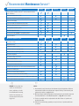
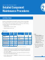
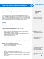
Recommended Maintenance Service[1]
Inspect and clean as necessary:
Start-Up
Monthly
Quarterly
Annually
Shutdown
Start-Up
Monthly
Quarterly
Annually
Shutdown
Inspect general condition of the unit[2] and check unit for unusual
noise or vibration
Inspect cold and hot water basins
Flush water distribution system/Inspect spray nozzles
Drain basin and piping
Inspect air intake louvers/Combined inlet shields
Check and adjust water level in cold water basin
Check operation of make-up valve
Check and adjust bleed rate
Check optional EASY CONNECT® Piping Arrangement
Inspect unit finish
Mechanical equipment system:
Check belt condition
Adjust belt tension[3]
[4]
Lubricate fan shaft bearings[4}
Lubricate motor base adjusting screw
See gear drive section on page 13 for detailed instructions and schedule.
Check and lubricate optional gear drive
Check drive alignment
Check motor voltage and current
Clean fan motor exterior
Check fan motor for proper rotation
Check general condition of the fan
Verify fan blade drain holes are not obstructed (hollow blade fans)
Check fan for uniform pitch
Check fan for rotation without obstruction
Check and recoat steel shafts with RUST VETO®
Check optional basin heater and stand alone BAC heater control panel
Check optional vibration cutout switch
DANGER: Do not perform any
NOTES:
service on or near the fans,
1.Recommended service intervals are the minimum for typical installations. Different
environmental conditions may dictate more frequent servicing. Follow all safety and
equipment precautions on pages 2 and 3.
motors, and drives, or inside
the unit without first ensuring
that the fans and pumps are
disconnected, locked out, and
tagged out.
2.When operating in ambient temperatures below freezing, the unit should be inspected
more frequently. Refer to “Cold Weather Operation” on page 28 for more details.
3.Tension on new belts must be readjusted after the first 24 hours of operation and
quarterly, thereafter.
4.Lubricate fan shaft bearings quarterly or every 2,000 hours of operation, whichever
occurs first.
Table of Contents
OPERATION & MAINTENANCE » SERIES 3000 AND XE-SERIES COOLING TOWERS
Safety and Equipment Precautions
2Danger
2Warning
2Caution
2Warranties
3Attention
3
General Maintenance Information
PART 1
Unit Operation and Storage
4
Start-Up Procedure
6
Extended Shutdown
7
Prolonged Outdoor Storage
PART 2
9
Detailed Component Maintenance Procedures
Cold Water Basin
10Fan
11 Fan Drive System
17 Fan Motors
17 Fan Shaft Bearings
18 Heat Transfer Section
18 Water Distribution System
19 Water Level Control
PART 3
PART 4
Bleed Rate
26 Bleed Rate
PART 5
Cold Weather Operation
28 Inspection & Maintenance
28 Fan Section Icing Protection
29 Basin Water and Internal Piping Freeze Protection
30 Freeze Protection for the Optional EASY CONNECT® Piping Arrangement
PART 6
Operation Considerations for Accessories
31 Basin Heater (Optional)
32 Vibration Cutout Switch (VCOS)
33 Stand Alone BAC Heater Control Panel (Optional)
Part 7
Fan Control
35 Variable Frequency Drive Operation
36 Resonant Speed Identification Procedure
PART 8 New Field Connections for TriArmor®
Corrosion Protection System Cold Water Basin
38 Installation Instructions
Corrosion Protection
22 Water Treatment
23 Corrosion and Scale Control
23 Biological Control
24 Chemical Treatment Requirements
24Passivation
25 Long Term Care of Stainless Steel
1
WWW.BALTIMOREAIRCOIL.COM
Safety and Equipment Precautions
Danger
• DANGER: Do not perform any service on or near the fans, motors, and drives, or inside the unit without first ensuring that the fans and
pumps are disconnected, locked out, and tagged out.
Warning
• WARNING: When access to the top of the unit is desired, the purchaser/end-user is cautioned to use appropriate means to comply with
applicable safety standards related to working on elevated surfaces.
• WARNING: When the fan speed of the unit is to be changed from the factory set speed, including changes achieved by the use of a
variable fan speed device, steps must be taken to avoid operation at or near the fan’s “critical speed” which could result in fan failure
and possible personal injury or damage.
• WARNING: The recirculating water system may contain chemicals or biological contaminants, including Legionella, which could
be harmful if inhaled or ingested. Personnel exposed directly to the discharge airstream and the associated drift mists, generated
during operation of the water distribution system and/or fans, or mists produced by high pressure water jets or compressed air (if
used to clean components of the recirculating water system), must wear respiratory protection equipment approved for such use by
governmental occupational safety and health authorities.
• WARNING: All electrical, mechanical, and rotating machinery are potential hazards, particularly for those not familiar with their design,
construction, and operation. Accordingly, use appropriate lockout procedures. Adequate safeguards (including the use of protective
enclosures where necessary) should be taken with this equipment both to safeguard the public from injury and to prevent damage to
the equipment, its associated system, and the premises.
• WARNING: A lockable disconnect switch should be located within sight of the unit for each fan motor associated with this equipment.
Before performing any type of service or inspection, make certain that all power has been disconnected, and the switch is locked out in
the “OFF” position.
• WARNING: Dangerous voltages are present in this equipment. Disconnect the electrical service of the source and follow proper lock out
and tag out procedures to de-energize the circuit before servicing or replacing components.
Caution
• CAUTION: Openings and/or submerged obstructions may exist in the bottom of the cold water basin. Use caution when walking inside
this equipment.
• CAUTION: Follow exposure control and personal protective equipment requirements as outlined in the MSDS for all recommended
lubricant and maintenance materials.
Warranties
Please refer to the Limitation of Warranties in the submittal packet applicable to and in effect at the time of the sale/purchase of these
products. Described in this manual are the recommended services for start-up, operation, and shutdown, and the approximate frequency
of each.
2
WWW.BALTIMOREAIRCOIL.COM
Attention
• The basin heater is not designed to prevent icing during unit operation.
• The heater control panel temperature/low level control can only be used with the supplied combination temperature/liquid level sensor
probe. Please contact your local BAC Representative for replacement parts.
• For the stand alone BAC heater control panel, do not operate the system unattended or for extended periods of time during test mode
(resistor across terminals T1 and T2). Operation in water temperatures above 45°F (7.2°C) could damage the unit.
• For heater control panels, do not operate the system unattended or for extended periods of time with terminals G1-G2 jumpered. A low
liquid level condition could occur, and the system will not shut off which could result in damage to the heater and unit.
• Check to ensure the controls for the fan motor are set to allow a maximum of six on-off cycles per hour to prevent motor overload.
• For fan motors controlled with VFDs with a switching frequency of 2.5 kHz, the line lead length cannot exceed 100 feet. If the switching
frequency is higher than 2.5 kHz and/or the line lead length exceeds 100 feet, a dV/dT output filter is recommended to protect the motor.
• When reversing the direction of fan rotation, allow the fan to come to a complete stop before restarting the motor.
• Only lubricate the bearings with one of the following compatible water resistant greases on page 17.
• Do not use steam or high pressure water to clean PVC eliminators or materials other than steel.
• Never use chloride or chlorine based solvents such as bleach or muriatic (hydrochloric) acid to clean stainless steel. It is important to
rinse the surface with warm water and wipe with a dry cloth after cleaning.
• Gear drives should not be used with Wye-Delta (Y-) motors.
• For installations with 2-speed motors when slowing from high speed, allow a minimum 15-second time delay for the fan to slow down
before energizing the low-speed winding.
• For towers with optional gear drives, do not mix synthetic lubricants and mineral oils. Attempt to use only one brand of lubricant at all
times. If the brand is changed, completely drain the old oil before filling the gear with new oil.
• Do not use power tools on the whisper quiet fan.
General Maintenance Information
The services required to maintain a piece of evaporative cooling equipment are primarily a function of the quality of the air and water in
the locality of the installation:
• AIR: The unit should be located such that unusual quantities of industrial smoke, chemical fumes, salt, or heavy dust do not enter the
equipmment. Such airborne impurities entering nto the equipment and absorbed by the recirculating water, which can form a corrosive
solution.
• WATER: As water evaporates from the equipment, dissolved solids are left behind, which were originally contained in the make-up water.
These dissolved solids may be either alkaline or acidic and as they are concentrated in the circulating water, they can cause scaling or
accelerated corrosion.
The extent of impurities in the air and water determines the frequency of most maintenance services and also governs the extent of water
treatment which can vary from a simple continuous bleed and biological control to a sophisticated treatment system. Refer to “Water
Treatment” on page 22 and “Biological Control” on page 23 for more details.
3
WWW.BALTIMOREAIRCOIL.COM
1
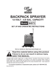
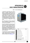
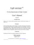
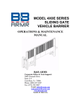
SERIES 3000 COOLING TOWER
Unit Operation and Storage
Fan Guard
BALTIDRIVE®
Power Train
Top Water Inlet
Fan Deck
Hot Water
Basin and Cover
Casing
Air Intake Louvers
Make-up Valve
Adjustable Float
Water Outlet
Connection
Cold Water
Basin
Suction
Strainer
BACross® Fill with
Integral Drift
Eliminators
Figure 1. Series 3000 Cooling Tower
Start-Up Procedure
DANGER: Do not perform any
service on or near the fans, motors,
General
without first ensuring that the
• If the unit is mounted on vibration isolators or isolation rails (by others), refer to the
vibration isolation manufacturer’s guidelines before loading/unloading weight from the
unit.
fans and pumps are disconnected,
• Verify the fan and system pump motors are disconnected, locked out, and tagged out.
and drives, or inside the unit
locked out, and tagged out.
4
W W W. B A LT I M O R E A I R C O I L.COM
Cleaning
• Drain the cold water basin with the strainer in place.
• Open the hot water basin covers and remove any dirt or debris from the hot water
basins.
Unit Operation and
Storage
Start-Up Procedure
• Clean and inspect the fan deck.
General
• Remove dirt and debris from the fan guard(s).
Cleaning
• Inspect and clean all spray nozzles.
Inspection
• Clean and inspect the mechanical components, such as the fan and motor.
Start-Up
• Flush the cold water basin to remove any accumulated dirt and debris.
• Remove, clean, and replace the cold water basin strainer.
Inspection
• Conduct external inspection of the equipment. Check for leaks, corrosion, and any
structural damage.
• Conduct internal inspection of the equipment. Check for anything unusual such as
structural or mechanical component damage.
• Inspect piping and connections.
• Thoroughly inspect the fan for any damage.
• Verify proper fan tip clearance. Refer to Fan “Inspection & Maintenance” on page 10.
• At seasonal start-up or after prolonged shutdown, check the motor insulation with an
insulation tester prior to the motor start-up.
• Check and adjust the belt tension or check gear drive oil levels.
• Check that the float operated make-up valve is operating freely.
ATTENTION: Check to ensure the
controls for the fan motor are set
to allow a maximum of six on-off
cycles per hour to prevent motor
overload.
Start-Up
Prior to seasonal start-up, lubricate the motor base adjusting screw (see Figures 4a and
4b on page 12) and the fan shaft bearings (see page 17). At initial start-up, bearings are
factory lubricated prior to shipment. However, if the unit has been idle for more than three
months, re-lubricate the bearings (see page 17). For towers with the optional gear drive
system, refer to page 13.
• Apply RUST VETO® to steel shafts.
• Fill the cold water basin with fresh water to the overflow level via the make-up valve.
• Set the make-up valve float so the water shuts off at the operating level (see Table 1,
page 9).
• For units with the optional EASY CONNECT® Piping Arrangement, verify the drain plug
is installed.
• Check that the float-operated make-up valve is operating freely. Closely monitor the
water level and adjust as necessary during the first 24 hours of operation.
• For the top inlets only, adjust the flow balancing valves to equalize flow to the hot
water basin(s). This valve may be provided by others or optionally supplied by BAC.
• Series 3000 Cooling Towers equipped with the optional EASY CONNECT® Piping
Arrangement do not require balancing the flow to the hot water basins.
• For multicell arrangements, balance the flow between the cells to obtain even water
distribution.
5
WW W. BALTIMORE A IR C O IL . C O M
ATTENTION: Check to ensure the
controls for the fan motor are set
to allow a maximum of six on-off
cycles per hour to prevent motor
overload.
• Adjust the valve (supplied by others) in the tower bleed line to achieve the desired
bleed rate by closing or opening the valve.
• Inspect the nozzles and heat transfer section as described in “Water Distribution
System” on page 19 (Figure 6).
• Execute one of the following biocide treatment programs while operating the
circulating pump and prior to operating the unit fans:
–– Resume treatment with the biocide that was used prior to shutdown. Operate the
pump only while maintaining the maximum recommended biocide residual for a
sufficient duration (residual and time will vary with the biocide) as recommended
by the water treatment supplier. Start the fan only after this treatment period is
completed.
–– Check the pH of the circulating water and, if necessary, adjust it to 7.0 - 7.6 pH.
Then, running the pump only, treat the system with sodium hypochlorite to maintain
a level of 4 to 5 mg/l (ppm) free chlorine (as Cl2) over a six hour period. Test kits for
measuring the free residual of chlorine are commercially available. Start the fan only
after this treatment period is completed.
• For units with the optional gear drive system, see page 13 for initial start-up.
• For initial start-up, briefly energize the fan motor(s) and note the direction of rotation.
The fan should rotate in the direction indicated by the arrow on the fan cowl.
• Run the fan in manual mode for several minutes to check for any unusual noise or
vibrations.
• For the BALTIGUARD™ Fan System, BALTIGUARD PLUS™ Fan System or 2-speed
motors: check that the starter incorporates a 15 second time delay when switching
from high to low speed.
• Check the operation of the vibration cutout switch (see page 32).
After 24 hours of operation
under thermal load, perform the
following services:
99Check the tower for any
• Once the cooling tower is operating, check the current and voltage of all three phases
(legs) of the fan motor with a heat load on the tower under warm ambient conditions.
The current must not exceed the motor nameplate rating.
• For units with VFDs, see page 35.
• For units with the optional Electric Water Level Control, see page 20.
unusual noise or vibrations.
99Check the operating water
level in the hot and cold water
basins.
99Adjust the make-up valve if
Extended Shutdown
necessary.
99Check the belt tension and
readjust if necessary.
99Inspect the spray nozzles and
heat transfer section.
Perform the following services whenever the unit is shutdown in excess of three days:
• If the unit is mounted on vibration isolators or isolation rails (by others), refer to the
manufacturer’s guidelines before loading/unloading weight from the unit.
• Disconnect, lock-out, and tag-out all fans and pumps.
DANGER: Do not perform any service
on or near the fans, motors, and
drives, or inside the unit without
first ensuring that the fans and
• Close the shut-off valve in the make-up water line (supplied by others) and drain cold
water basin and all exposed water piping. Heat trace and insulate all exposed piping.
• To minimize the risk of biological contamination during shutdown, it is recommended
the entire system be drained.
pumps are disconnected, locked
• Clean all debris, such as leaves and dirt, from the interior and exterior of the unit,
including the louvers or the optional combined inlet shields.
out, and tagged out.
• Clean and flush the cold water basin with the basin strainer in place.
6
W W W. B A LT I M O R E A I R C O I L.COM
• Leave the cold water basin drain open so rain and melting snow will drain from the
unit.
• Clean the basin strainer and re-install.
• Cover the fan discharge to keep out dirt and debris.
• Lubricate the fan shaft bearings, motor base, and motor base adjusting screw.
• Apply RUST VETO® to steel shafts.
• Inspect the protective finish on the unit. Clean and refinish as required. Refer to
“Corrosion Protection” on page 22 for more details.
• Lockout the fan motor starting device in the “OFF” position to ensure personal safety
in case of future inspection or service.
Unit Operation and
Storage
Start-Up Procedure
Start-Up
Extended Shutdown
Prolonged Outdoor Storage
Storage Preparation
Motor Recommendations
Prolonged Outdoor Storage
Storage Preparation
• Conduct the “Extended Shutdown” procedure on page 6 if the unit is installed.
• Ensure the cold water basin is fully drained and the drain is open.
• For storage prior to installation, all components and accessories, which sometimes
ship inside the tower and are not a permanent fixture in the basin, should be removed
and stored indoors.
• Remove the drain plug from the optional EASY CONNECT® Piping Arrangement. The
drain should remain open throughout prolonged storage period. Retain the drain plug
for future installation.
ATTENTION: Covering the unit with
a clear plastic tarpaulin during
storage can trap heat inside the
unit and cause damage to the
PVC components. If units must be
covered during storage, an opaque,
reflective tarp should be used.
• Remove and store fan belts (if supplied) at room temperature. Tag belts appropriately
for future identification.
• Apply a weather-resistant lubricant or heavy grease such as Anti-Seize (BAC Part #
160069) to all exposed threaded or flanged connections and adjustable motor base
threaded rod.
• Insert desiccant bags into the control panel (if supplied) to absorb moisture. Seal the
control panel for storage.
• Spray coat electrical component housings (if supplied) with a suitable protective
coating, such as Cosmoline® Weathershed, and individually cover them with plastic
taking care to leave openings for free air circulation.
• Inspect the protective finish on the unit. Clean and refinish as required. Refer to
“Corrosion Protection” on page 22 for more details.
Motor Recommendations
BAC standard motors are designed for storage at ambient temperatures of -20ºF to 104ºF
(-28.9ºC to 40ºC). Prolonged periods of exposure above or below these specified conditions
could degrade components of the motor and cause malfunction or premature failure.
• Motors should be removed and stored inside whenever possible. When indoor storage
is not possible the motors must be covered with a tarpaulin. Do not use plastic or
plastic film. This cover should extend below the motor and be secured; however, it
should not tightly wrap the motor. This will allow the captive air space to breathe,
minimizing formation of condensation.
• Care must also be taken to protect the motor from flooding or from harmful chemical
vapors.
DANGER: Do not perform any
service on or near the fans, motors
and drives, or inside the unit
without first ensuring that the
fans and pumps are disconnected,
locked out and tagged out.
7
WW W. BALTIMORE A IR C O IL . C O M
• The storage area should be free from ambient vibration. Excessive vibration can cause
bearing damage.
• Precautions should be taken to prevent rodents, snakes, birds, or other small animals
from nesting inside the motors. In areas where they are prevalent, precautions must
also be taken to prevent insects from gaining access to the interior of the motor.
• If not stored indoors in a controlled environment, some form of heating must be
utilized to prevent condensation from accumulating in the motor. This heating should
maintain the winding temperature at a minimum of 9ºF (-12.8ºC) above the ambient
temperature of the surrounding environment, keeping it from dropping below the dew
point where condensation could form inside the motor. If space heaters are supplied,
they should be energized. Request the required voltage and transformer capacity from
your local BAC Representative. A third option is to use an auxiliary heat source and
keep the winding warm by either convection or blowing warm air into the motor.
• Rotate the motor shaft monthly to redistribute bearing grease.
Maintenance Requirements
• Rotate all fans and motor shafts monthly by hand. Hand-turning will ensure that the
shafts and bearings are free and will redistribute grease within the bearings. Keep
hands away from pinch points such as bolts and sheaves.
• Inspect the cold water basin monthly to ensure that the drain is open and remove any
leaves or debris that may have accumulated in the cold water basin.
• Inspect axial fans prior to start-up and at least once annually to ensure that the blades
are tight and that there is no obvious corrosion between the hub and the fan blade.
• Inspect the rust preventative coating on all motor external machined surfaces
including shaft extensions monthly. If necessary, re-coat the surfaces with RUST
VETO®.
Start-Up Preparation After Prolonged Storage
DANGER: Do not perform any
service on or near the fans, motors
and drives, or inside the unit
without first ensuring that the
fans and pumps are disconnected,
locked out and tagged out.
Keep in mind that start-up procedures after long periods of storage are just as important as
pre-shutdown procedures.
• Motors should be thoroughly inspected and cleaned and restored to pre-storage
condition.
• Inspect the axial fan prior to start-up to ensure that the blades are tight and that there
is no obvious corrosion between the hub and the fan blades. Do not energize the fan
if there is obvious corrosion of fan components. Loose fan blades could result in fan
failure and possible injury or damage.
• Reinstall all fan belts, motors, door gaskets, and drain plugs (as applicable), and
remove all protective coverings.
• For units stored prior to installation, conduct rigging procedures as directed in the
unit’s Rigging and Assembly Instructions, available on www.BaltimoreAircoil.com or by
contacting your local BAC Representative.
• Perform an insulation test of motor windings to ensure satisfactory insulation
resistance.
• Conduct full start-up procedure as stated in the “Start-Up Procedure” on page 4. Be
especially thorough for cleaning and inspection prior to start-up.
• For units with the optional gear drive system, the gear box must be fully drained,
then refilled with new oil at or near the middle of the oil level sight gauge to prevent
damage. Then, follow the steps in “Initial Start-up” on page 13.
8
W W W. B A LT I M O R E A I R C O I L.COM
2
SERIES 3000 COOLING TOWER
Detailed Component
Maintenance Procedures
Cold Water Basin
As water circulating though the cooling tower is cooled, it collects in the cold water
basin and passes though the suction strainer into the system. The cold water basin
is constructed from one of the following materials of construction and the following
maintenance applies to all basin materials of construction.
• Galvanized steel
• TriArmor® Corrosion Protection System
• Welded Type 304 stainless steel
Water Levels
At
Overflow
Level (in.)
At
Operating
Level (in.)[2]
At
Overflow
Level (in.)
At
Operating
Level (in.)[2]
S3E/XES3E-8518-05x,
8518-06x
14 1/8
8 3/4
S3E/XES3E-1222-12x
21 5/8
9 3/4
S3E/XES3E-8518-07x
17 1/2
8 3/4
S3E/XES3E-1222-13x,
1212-14x
22[1]
9 3/4
S3E/XES3E-1020-06x
14 3/4
8 3/4
S3E/XES3E-1424-07x
16[1]
9 3/4
S3E/XES3E-1020-07x
15 1/2
8 3/4
S3E/XES3E-1424-12x
19 5/8[1]
9 3/4
S3E/XES3E-1222-06x
14 5/8
8 3/4
S3E/XES3E-1424-13x
20 1/4[1]
9 3/4
S3E/XES3E-1222-07x
15 1/4
8 3/4
S3E/XES3E-1424-14x
21[1]
9 3/4
S3E/XES3E-1222-10x
20 1/8
9 3/4
Model Number
Model Number
Table 1. Cold Water Basin Water Levels (Measured From Inside the Cold Water Basin)
NOTES:
1.The following materials of
construction combinations have a
basin overflow height of 18 1/2”:
- TriArmor® Corrosion Protection
System or stainless steel cold
water basin with either
galvanized steel or thermosetting
hybrid polymer frame
- EVERTOUGH™ Construction
2.These are the standard operating
levels. If the connection size is
custom, contact your local BAC
representative.
• The operating water level in the cold water basin will vary with system thermal load
(evaporation rate), the bleed rate employed, and the make-up water supply pressure.
• The make-up valve controls the operating level, which should be maintained at the
levels shown in Table 1.
• Check the operating water level monthly, and readjust the float when necessary to
maintain the recommended operating level.
• Consult “Water Level Control” on page 19 for information on how to set and maintain
the basin operating level.
9
WW W. BALTIMORE A IR C O IL . C O M
Inspection & Maintenance
CAUTION: Openings and/or
submerged obstructions may exist
in the bottom of the cold water
basin. Use caution when walking
inside this equipment.
• Inspect the cold water basin regularly. Remove trash or debris that may have
accumulated in the basin or on the strainer.
• Quarterly, or more often if necessary, drain, clean, and flush the entire cold water
basin with fresh water. This will remove the sediment, which can collect in the
basin during operation. If not removed, sediment can become corrosive and cause
deterioration of the protective finish of metallic basins.
–– When flushing the basin, leave the strainer in place to prevent debris from entering
the system.
–– Remove the strainer after the basin has been flushed.
–– Clean and replace the strainer before refilling the basin with fresh water.
• Adjust the float to maintain the design operating level. See Table 1 on page 9.
Fan
The Series 3000 Cooling Tower uses an axial fan. Thoroughly inspect the fan for damaged
or deteriorated fan blades and replace the fan as required.
Inspection & Maintenance
• If the unit is already in operation, while the fan is running, check for any unusual
noise or vibration.
DANGER: Do not perform any service
on or near the fans, motors, and
drives, or inside the unit without
first ensuring that the fans and
pumps are disconnected, locked
out, and tagged out.
ATTENTION: Do not use power tools
• With the fan off and the motor disconnected, locked out, and tagged out, check the
general condition of the fan:
–– Inspect for any loose or missing bolts in the fan shaft bushing, the fan hub, and the
fan shaft bearing(s).
–– Check the fan blades for looseness, first by twisting the blade by hand, and then by
moving the blade tip up and down. There should be no play or slippage.
–– Inspect each blade for excessive scale build-up that could cause vibration.
–– Check each blade for any cracks. If cracks are found, the fan motor should be
locked out until the fan is replaced. Contact your local BAC Representative for
assistance.
• For the optional whisper quiet fan only:
on the whisper quiet fan.
Model Number
S3E/XES3E-1020-x
S3E/XES3E-1424-12x, 1424-13x, 1424-14x
Fan Dia.
Allen Head
Bolt Type
Tightening
Torque
9'
12 mm
50 ft-lbs
11’ to 13'
16 mm
90 ft-lbs
Table 2. Whisper Quiet Fan Tightening Torque
–– During first week of operation, the blades shall be inspected at least once to ensure
that all nuts are tightened to the torque value listed in Table 2.
–– After the first week of operation, the blades shall be inspected at regular intervals,
a minimum of once every month, for deposits and damage. To remove deposits, use
steel wool as an abrasive along with a mild detergent or very mild form of solvent.
Lye must not be used because it attacks aluminum readily.
–– At regular intervals, the hub shall be inspected for damage, including bending and
twisting.
10
W W W. B A LT I M O R E A I R C O I L.COM
–– To ensure optimal functioning and operational safety of the impeller, it is necessary
to at least once a year check the tightening torque of the bolt connections (refer to
Table 2) and replace corroded bolts and nuts.
• With the fan off and the motor disconnected, locked out, and tagged out, check the
general condition of the fan:
–– Tip Clearance: Check the clearance between the tip of the blade and the fan cowl.
The clearance should be sufficient to prevent the fan blades from contacting the
fan cowl during operation. Contact your local BAC Representative if there are any
concerns.
Detailed Component
Maintenance
Procedures
Cold Water Basin
Inspection & Maintenance
–– Drain Holes: On hollow blades, the drain hole in the blade tip should be
unobstructed. Tip: Use a piece of wire to clear the drain hole.
Fan
–– Blade Pitch: Check to ensure that the blades are all at the same pitch. If uncertain,
measure the pitch with an inclinometer. All blades should be within 1/2° of each
other.
Fan Drive System
–– Rotation: Turn the fan by hand to ensure that it moves freely with no rough spots,
binding, or other malfunctions that could cause vibration or fan motor overload.
While rotating the fan, check the blade tracking. All blades should track within a 1”
band at any single point around the cowl.
–– Direction of Rotation: On initial start-up, or if the fan motor has been rewired, briefly
energize the fan motor and note the direction of fan rotation. It should rotate in the
direction indicated by the arrow on the fan cowl.
–– Operation: On initial start-up, run the fan in the manual position for several minutes,
and check for any unusual noises or vibration.
Inspection & Maintenance
BALTIDRIVE® Power Train/
BALTIGUARD™ and
BALTIGUARD PLUS™ Fan System
ATTENTION: Check to ensure the
controls for the fan motor are set
to allow a maximum of six on-off
cycles per hour to prevent motor
overload.
Fan Drive System
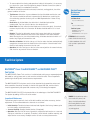
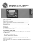
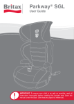
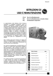
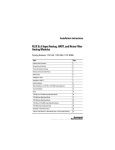
BALTIDRIVE® Power Train/BALTIGUARD™ and BALTIGUARD PLUS™
Fan System
The BALTIDRIVE® Power Train consists of a solid-backed, multi-groove, neoprene/polyester
belt rated for cooling tower service, and corrosion-resistant sheaves. These components
provide high reliability with low maintenance requirements.
The BALTIGUARD™ Fan System consists of two standard single-speed fan motors and
drive assemblies. One drive assembly is sized for full speed and load, and the other is
sized for approximately 2/3 speed and consumes only 1/3 the design horsepower.
The BALTIGUARD PLUS™ Fan System builds on the advantages of the BALTIGUARD™
Fan System by adding a VFD to one of the motors.
Figure 2. BALTIGUARD™ Fan System
DANGER: Do not perform any service
Inspection & Maintenance
on or near the fans, motors, and
These drives require a periodic check of the belt condition and, when necessary, tension
adjustment. The recommended service intervals are as follows:
drives, or inside the unit without
• Initial Start-Up: The drive has been tensioned and aligned at the factory; however, prior
to initial startup, check belt tension.
• Seasonal Start-Up: Readjust the belt tension (if required).
• Operation: After the first 24 hours of operation, readjust the belt tension on a new unit
start-up or installation of a new belt. Thereafter, check the belt condition monthly, and
adjust tension as necessary. Readjust tension at least once every three months.
first ensuring that the fans and
pumps are disconnected, locked
out, and tagged out.
11
WW W. BALTIMORE A IR C O IL . C O M
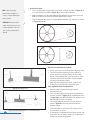
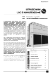
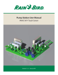
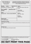
• Belt tension check:
NOTE: If belts are properly
tensioned, there should be no
“chirp” or “squeal” when the fan
motor is started.
ATTENTION: Check to ensure the
–– Place a straight edge along the belt from sheave to sheave as shown in Figure 3a, or
use a tape measure as shown in Figure 3b to measure belt deflection.
–– Apply a moderate force by hand (approximately 40 lbs/275 kPa) evenly across the
width of the belt in the center of the span between the sheaves.
–– There is adequate belt tension if the belt deflects between 1/4” and 3/8” as shown
in Figures 3a and 3b.
controls for the fan motor are set
to allow a maximum of six on-off
cycles per hour to prevent motor
overload.
Figure 3a. Belt Tension with a Straight Edge
Figure 3b. Belt Tension with a Tape Measure
• Belt tension adjustment (if required):
–– Loosen the lock nut on the motor base adjusting screw.
–– Turn the motor base adjusting screw clockwise to
tension the belt or counterclockwise to relieve belt
tension. During adjustment of the belt tension, rotate
the drives several times by hand to evenly distribute
the tension throughout the belt.
–– When the belt is properly tensioned, retighten the
locking nut on the motor base adjusting screw.
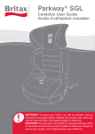
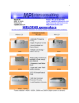
Figure 4a. Standard Drive Alignment
• Drive alignment check and adjustment:
–– Check the drive alignment annually to ensure
maximum belt life.
–– Place a straight edge across the driver and the driven
sheaves as shown in Figure 4a for standard drives and
in Figure 4b for the BALTIGUARD™ Fan System or the
BALTIGUARD PLUS™ Fan System.
–– The straight edge should contact all four points as
shown in Figure 4a indicating that the drives are
properly aligned.
Figure 4b. BALTIGUARD™/BALTIGARD PLUS™ Fan System Drive Alignment
12
W W W. B A LT I M O R E A I R C O I L.COM
–– There should be no more than 1/16” deviation from
the four points of contact.
–– If realignment is required loosen the motor sheave and
align it with the fan sheave. Allow 1/4” for draw-up as
the bushing screws are tightened.
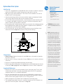
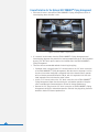
Optional Gear Drive System
Initial Start-Up
• If the unit is equipped with an extended lubrication line option or external sight glass,
make sure the ball valve located at the gear box is open prior to start-up.
• BAC ships all gear drives filled with oil. The initial oil level should be at or near the
middle of the oil level sight gauge.
• Internally mounted gear drives are factory installed, aligned, and tightened. Double
check all gear drive fasteners after the unit has been installed.
• On units with externally mounted motors, install and align the motor and drive shaft
in accordance with BAC’s installation instructions. Recheck the alignment and all
external fasteners after two weeks of operation.
• On installations with variable frequency drives, do not operate the standard gear drives
below 450 RPM motor speed (gear input speed). For speeds less than 450 RPM, a
low speed option gear drive must be supplied.
• Prior to the start-up, check all fittings on the gear drive to ensure that there are no
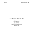
visible leaks. Refer to Figure 5 for locations of the gear drive fittings.
Detailed Component
Maintenance
Procedures
Fan Drive System
BALTIDRIVE® Power Train/
BALTIGUARD™ and
BALTIGUARD PLUS™ Fan
System
Optional Gear Drive System
ATTENTION: Gear drives should
not be used with Wye-Delta (Y-)
motors.
NOTE: Continued operation at a
speed which resonates with the
gear drive system may result in
torsional vibrations which can
Air Breather Plug
Name Plate
damage system components. The
most common indicator of torsional
Oil Fill Elbow
vibration is an unusual rumbling or
grinding noise from the gear drive
Oil Level
Sight Gauge
at a narrow speed range. The noise
will decrease to normal levels when
Oil Drain Plug
the speed is increased or decreased
away from the offending speed
Figure 5. Gear Drive
Change Interval
range. This noise is not indicative
of a defect, but results when the
• Initial oil change: Replace the original oil after 500 hours or four weeks of operation,
whichever comes first.
vibratory torque exceeds the drive
• After the initial oil change, change the oil every 2,500 hours or six months, whichever
comes first.
separate and clash together very
• Drain the oil at operating temperature through the drain plug.
applications, avoid operation near
• Refill the gear drive through the oil fill elbow with the recommended type and amount
of lubricant (Table 3, page 15). Refer to Figure 5 for locations of these components.
torque, causing the gear teeth to
rapidly. On variable frequency
this resonance speed by locking out
the resonance speed range.
Inspection & Maintenance
• Maintain the oil level at or near the middle of the oil level sight gauge. The oil level
should always be visible in the sight gauge window when the unit is not operating/
energized, and the oil is at ambient temperature.
• Check oil level weekly with the unit idle. On units supplied with an external sight
gauge, check the oil level of the external sight gauge and the sight gauge on the gear
drive to ensure that the proper amount of oil is in the gear drive.
• Add oil through the oil fill elbow if level is below the oil level sight gauge.
• The standard oil provided is mineral oil. Synthetic lubricants are also available as an
option (see Fan Drive System “Lubrication” on Page 15).
13
WW W. BALTIMORE A IR C O IL . C O M
• Refer to Table 3 on Page 15 for normal operating oil capacity of each gear drive.
• Refer to Table 4 on Page 16 or the gear drive nameplate for specific gear model number
for each unit.
• Quarterly check to ensure proper alignment of all system components.
• Check to ensure that all bolts and external fasteners are tight.
• BAC recommends daily visual inspections and observation for oil leaks and unusual
noises and vibrations. If any of these occur, shutdown the unit until the cause is found
and corrected.
• If equipped with an external oil line and site gauge, check weekly to make sure the
breather hole at the top of the sight gauge is open.
ATTENTION: If noise or vibration
persists, shut the unit down and
correct the cause before continuing
operation.
ATTENTION: For installations with
2-speed motors when slowing
from high speed, allow a minimum
15-second time delay for the fan
to slow down before energizing the
low-speed winding.
ATTENTION: When reversing the
direction of rotation, allow the fan
to come to a complete stop before
restarting the motor.
Routine Maintenance During Operation
• Periodically recheck the alignment and tighten external fasteners as necessary. No
special break-in procedures are required.
• Excessive noise or vibration at initial operation is an indication of one or more of the
following:
–– Misalignment
–– Imbalance of the fan or other rotating parts
–– Improperly adjusted fan blades
–– Operation at the mechanical equipment resonant frequency
• For gears equipped with the low speed option, operate the fan motor at full speed for
at least five minutes weekly to supply oil to the upper bearing reservoir inside the gear
casing.
• During periods of inactivity, the lubricant does not constantly lubricate the internal
parts of the gear drive, leaving the gear drive susceptible to corrosion. Therefore, the
following special precautions are necessary during periods of inactivity:
–– For best results, let the gear drive cool for approximately 4 hours after shutdown.
–– Start the fan and let it run for approximately 5 minutes. This will coat the internal
parts of the drive with cool oil.
–– Thereafter, run the fan for 5 minutes once a week, throughout the shutdown period
to maintain the oil film on the internal parts of the gear drive.
• Clean the outside of the gear drive at least quarterly.
Prolonged Shutdown
Follow the procedures below when a gear drive will not be used for a prolonged period of
time, including seasonal shutdown.
• Drain all of the old oil from the gear drive and properly discard.
• Re-install drain plug.
• Remove the air breather from the gear drive.
ATTENTION: Upon start-up, the
gear box must be drained back to
the proper level before operation
to prevent damage. The fan motor
should be locked and tagged out in
order to prevent operation until the
oil level is returned to normal.
• Completely fill the gear drive through the air breather port with a recommended
lubricant listed on page 15. Once the gear is filled, do not use the fan motor to rotate
the gear as pressure will build up in the gear box and cause damage.
• After completely filling the gear with oil, plug the previously removed air breather port,
and all remaining open ports. Use steel plugs to plug the openings, and store the air
breather so that you can reuse it when the gear drive is put back in operation.
• Securely attach a “warning” tag to the gear box and motor starter stating that it has
been “overfilled” to remind start-up personnel that they need to drain the gear oil back
to the proper level before using.
• To establish a moisture barrier, cover the drive with a tarpaulin or other protective cover.
14
W W W. B A LT I M O R E A I R C O I L.COM
• For start-up after prolonged shutdown, the gear box must be fully drained, then refilled
with new oil at or near the middle of the oil level sight gauge to prevent damage.
Re-install the air breather which was removed prior to the prolonged shutdown. Then,
follow the steps in “Initial Start-up” on page 13.
Lubrication
• Use only rust and oxidation inhibited gear oils in accordance with AGMA (American
Gear Manufacturer’s Association), Standard 9005-E02.
• The ambient temperature at the gear drive is 20°F to 120°F (-7°C to 49°C) for mineral
oils and -20°F to 150°F (-29°C to 66°C) for synthetic lubricants.
• The AGMA lubricant number is 5 for mineral oils and 5S for synthetic lubricants.
Detailed Component
Maintenance
Procedures
Fan Drive System
Optional Gear Drive System
• The ISO grade is 220 for both mineral oils and synthetic lubricants.
• Do not use gear oils containing extreme pressure (EP) additives.
• Recommended mineral oils:
NOTE: List of brand names is for
identification only and are not
–– Atlantic Richfield – Duro 220
exclusive recommendations.
–– Chevron Oil – Rando HD 220
–– Cities Service Oil – Citgo Pacemaker 220
–– Conoco – Hydroclear Multipurpose R&O Oil 220
ATTENTION: Do not mix synthetic
–– Exxon – Teresstic 220
lubricants and mineral oils.
–– Gulf Oil – Harmony 220
Attempt to use only one brand of
–– Mobil Oil – DTE Oil BB
lubricant at all times. If the brand
–– Pennzoil – Pennzbell TO 220
is changed, completely drain the
–– Philips Petroleum – Magnus 220
old oil before filling the gear with
–– Shell Oil – Morlina SD 220
new oil.
–– Sun Oil – Sunvis 9220
–– Texaco – Regal 220 R&O, Code 1531
–– Total – Carter 220
NOTE: Certain gear drive
• Recommended synthetic lubricants:
–– Chevron Oil – Clarity 220 Synthetic
components might be incompatible
–– Conoco – Syncon 220 R&O Oil
with the various base stocks used to
–– Mobil Oil – SHC 630
make synthetic lubricants. Contact
• When the ambient temperature exceeds 180°F (82°C) or the gear drive is started at
an ambient temperature less than 20°F (-7°C), a synthetic lubricant is recommended.
When mineral oils are used in operation at ambient temperature less than 20°F (-7°C)
lube oil heaters are required. Each unit has provisions for an internal oil reservoir
heater. Heaters and synthetic oil are extra cost accessories and can be ordered with
new units or may be ordered and installed in existing units.
your local BAC Representative prior
to using any synthetic lubricant not
listed.
• The vertical and horizontal shafts are equipped with grease lubricated dual seals.
Relubrication is not required.
Gear Model
Gallons
Liters
65
0.5
2
85
1
4
110
2
8
135
3
11
NOTE: For units with the extended
155
5.5
21
lubrication line option, additional
175
5.5
21
oil beyond the capacities listed in
Table 3. Normal Operating Oil Capacity
Table 3 will be required to fill the
oil line.
15
WW W. BALTIMORE A IR C O IL . C O M
Gear
Model for
Standard
Fan
Gear
Model for
Low Sound
Fan
Gear
Model for
Standard
Fan
Gear
Model for
Low Sound
Fan
8518-05J
65
85
8518-05K
65
85
1222-12M
110
135
1222-12N
110
8518-05L
65
135
85
1222-12O
110
8518-05M
135
85
85
1222-12P
110
135
8518-06H
85
-
1222-12Q
110
135
8518-06J
65
85
1222-12R
110
155
8518-06K
65
85
1222-12S
135
155
8518-06L
65
85
1222-13M
110
135
8518-06M
85
85
1222-13N
110
135
8518-06N
85
85
1222-13O
110
135
8518-06O
85
85
1222-13P
110
135
S3E and XES3E
Truncated Model
Number
NOTE: For projects with whisper
quiet fans, please contact your local
BAC Representative.
16
W W W. B A LT I M O R E A I R C O I L.COM
S3E and XES3E
Truncated Model
Number
8518-07H
85
-
1222-13Q
110
135
8518-07J
65
85
1222-13R
110
155
8518-07K
65
85
1222-13S
135
155
8518-07L
65
85
1222-14M
110
135
8518-07M
85
85
1222-14N
110
135
8518-07N
85
85
1222-14O
110
135
8518-07O
85
85
1222-14P
110
135
8518-07P
110
110
1222-14Q
110
135
1020-06J
85
85
1222-14R
110
155
1020-06K
85
110
1222-14S
135
155
1020-06L
85
85
1222-14T
155
175
1020-06M
85
110
1424-07M
110
135
1020-06N
85
110
1424-07N
110
135
1020-06O
85
110
1424-07O
110
135
1020-07J
85
85
1424-07P
110
135
1020-07K
85
110
1424-07Q
110
135
1020-07L
85
85
1424-07R
110
155
1020-07M
85
110
1424-12P
110
175
1020-07N
85
110
1424-12Q
135
175
1020-07O
85
110
1424-12R
135
175
1020-07P
110
110
1424-12S
155
175
1222-06K
85
85
1424-12T
175
175
1222-06L
85
135
1424-13P
110
175
1222-06M
85
110
1424-13Q
135
175
1222-06N
85
110
1424-13R
135
175
1222-06O
110
110
1424-13S
155
175
1222-07K
85
85
1424-13T
175
175
1222-07L
85
135
1424-14P
110
175
1222-07M
85
110
1424-14Q
135
175
1222-07N
85
110
1424-14R
135
175
1222-07O
110
110
1424-14S
155
175
1222-07P
110
135
1424-14T
175
175
1222-07Q
110
135
1222-07R
110
135
1222-10M
110
135
1222-10N
110
135
1222-10O
110
135
1222-10P
110
135
1222-10Q
110
135
1222-10R
110
155
1222-10S
135
155
Table 4. Gear Model/Unit for Standard Fans and Low Sound Fans
Fan Motors
Series 3000 Cooling Towers use cooling tower duty, premium efficient, totally enclosed,
motor(s).
Inspection & Maintenance
• Clean the outside of the motor at least quarterly to ensure proper motor cooling.
• After prolonged shutdowns, check the motor insulation with an insulation tester prior
to restarting the motor.
• Check the motor voltage and current following start-up and every three months while
in operation.
Detailed Component
Maintenance
Procedures
Fan Drive System
Optional Gear Drive System
Fan Motors
Inspection & Maintenance
Adjustable Motor Base
Fan Shaft Bearings
Inspection & Maintenance
ATTENTION: Check to ensure the
controls for the fan motor are set
Adjustable Motor Base
to allow a maximum of six on-off
Coat the motor base slides and adjusting screws prior to start-up, every three months while
in operation, and following shutdown. Use good quality corrosion inhibiting grease such as
one of those recommended for lubricating the fan shaft bearings on page 17.
overload.
cycles per hour to prevent motor
Fan Shaft Bearings
Two pillow block ball bearings support the fan shaft. Each bearing is equipped with a
lubrication fitting and a slinger/locking collar to keep out moisture.
Inspection & Maintenance
• Only lubricate the bearings with a manual grease gun or BAC’s optional Automatic
Bearing Greaser. Do not use high-pressure grease guns since they may rupture the
bearing seals.
• Only lubricate the bearings with one of the following compatible water resistant
greases which are suitable for ambient temperatures ranging from -65ºF (-53.9ºC) to
+250ºF (121.1ºC).
DANGER: Do not perform any service
on or near the fans, motors, and
drives, or inside the unit without
first ensuring that the fans and
pumps are disconnected, locked
out, and tagged out.
NOTE: For programming, operation,
and trouble shooting of the greaser,
consult the user manual shipped
with the greaser. This manual is
–– Amoco - Rycon Premium #3
also available through your local
–– Chevron - SRI
BAC Representative.
–– Citgo - Polyurea MP2™
–– Conoco - Polyurea 2™
–– Exxon - Polyrex® EM
–– Exxon - Unirex N™
NOTE: Gear oils containing extreme
pressure (EP) additives are not
recommended, and should never be
–– MobilGrease® - AW2
used on cooling towers with gear
–– Shell - Alvania RL3™
drives.
–– Shell - Alvania #3
–– Shell - Dolium “R”
–– SKF - LGHP2™
–– Unocal 76 - Unilife Grease™
17
WW W. BALTIMORE A IR C O IL . C O M
• Lubricate the bearings as follows:
–– Initial Start-up: Normally, no lubrication is required since the bearings have been
lubricated at the factory prior to shipment. However, if the cooling tower has been
stored at the job site or more than three months, both bearings should be lubricated
with new grease before initial operation. When lubricating, purge the old grease
from the bearing by gradually adding grease until a bead of new grease appears at
the seal on the underside of the bearing.
–– Seasonal Start-up: Purge the bearings with new grease prior to start-up.
–– Operation: Purge the bearings with new grease every three months while in
operation, or 2,000 hours, whichever comes first.
–– Extended Shutdown: Purge the bearings with new grease before and after any
prolonged storage or downtime.
Heat Transfer Section
Fill & Drift Eliminator
The Series 3000 has PVC fill with integral drift eliminators.
Inspection & Maintenance
• Inspect and clean the fill with the integral eliminators at least quarterly.
• The inspection procedure is as follows:
–– Shut-off the fan and the system pump.
–– Inspect the fill for obstructions, damage and fouling.
• Remove any obstructions from the fill.
• Remove any minor fouling chemically. Contact your local water treatment consultant
for advice.
• Major fouling requires cleaning and flushing.
Water Distribution System
Hot Water Basin
The hot water basins are located on the fan deck. The system water enters the cooling
tower through the hot water basins (refer to Figure 6, page 19). A series of nozzles, which
distribute water over the fill, are located in the hot water basin. There are four materials
of construction for the hot water basin: Galvanized steel, Thermosetting Hybrid Polymer,
Type 304 stainless steel and Pultruded Fiberglass Reinforced Polyester (PFRP).
18
W W W. B A LT I M O R E A I R C O I L.COM
Operating Level
At design flow, the operating level should not be less than 2 inches or greater than 6
inches deep.
Inspection and Maintenance
• Quarterly, or more often as required, remove any dirt or debris which may clog the
nozzles. Seasonally, clean and flush the hot water basin with fresh water.
Detailed Component
Maintenance
Procedures
Fan Shaft Bearings
Inspection & Maintenance
Heat Transfer System
Fill & Drift Eliminator
• Access to the nozzles requires removal of the hot water basin covers.
–– To remove the covers turn the knobs to remove the threaded studs (Figure 6). Then,
lift the hot water basin covers vertically by using the attached handles. Once the hot
water basin covers are removed, the nozzles may be cleaned.
• If access to the nozzles under the pre-distribution chamber is required, remove
the hardware that fastens the tabbed baffles, then remove the panels. Retain the
hardware to re-install the tabbed baffles.
Water Distribution System
Hot Water Basin
Operating Level
Inspection and Maintenance
Optional EASY CONNECT®
Piping Arrangement
Water Level Control
ATTENTION: Do not use steam or
high pressure water to clean PVC
eliminators or materials other than
steel.
Figure 6. Hot Water Basin Cover Removal
Optional EASY CONNECT® Piping Arrangement
The Series 3000 Cooling Tower has an optional EASY CONNECT® Piping Arrangement,
which is equipped with a capped cleanout connection. The water to be cooled enters the
tower through a single connection and passes through the EASY CONNECT® Chamber,
supplying water to both hot water basins. See Figure 7, page 30.
Water Level Control
There are two types of water level controls used on Series 3000 Cooling Towers:
• Mechanical make-up valve assembly
• Optional electric water level control package
The Series 3000 water make-up valve assembly is located at the connection end of the
unit.
19
WW W. BALTIMORE A IR C O IL . C O M
Mechanical Make-up Valve Assembly
NOTE: If the unit has been ordered
with the optional electric water
level control package or is intended
for remote sump application, a
mechanical water make-up valve
will not be provided.
A float-operated mechanical water make-up assembly is furnished as standard equipment
on the cooling tower. The standard make-up assembly consists of a corrosion resistant
make-up valve connected to a float arm assembly actuated by a polystyrene-filled plastic
float. The float is mounted on an all-thread rod held in place by wing nuts. The cold water
basin operating water level can be adjusted by repositioning the float and all-thread rod
using the wing nuts provided.
• Inspect the make-up valve assembly monthly and adjust if necessary.
• Inspect the valve annually for leakage. Replace the valve seat if necessary.
• Maintain the make-up water supply pressure between 15 psig and 50 psig for proper
operation. BAC recommends a pressure regulator valve (provided by others) for
pressures over 50 psig.
• Set the initial basin water level by adjusting the wing nuts so that the make-up valve is
completely closed when the water level in the cold water basin is at the operating level
as stated in Table 1 on page 9.
• With the design thermal load and the average water pressure (15 to 50 psig) at the
valve, the above setting will produce operating water levels as stated in Table 1 on
page 9.
• If the thermal load is less than the design load at the time of unit start-up, the
procedure may produce operating levels greater than those shown in Table 1. If
operating levels are higher than specified, readjust the float in order to attain the
recommended operating level.
• Closely monitor the water level in the cold water basin and adjust the level if necessary
during the first 24 hours of operation.
• Operating at the recommended water level will ensure that the unit basin contains
sufficient water volume to prevent air entrainment in the circulating pump during
system start-up and provides sufficient excess basin capacity to accept the total
system pull-down volume.
Optional Electric Water Level Control Package
As an option, an electric water level control package is available in lieu of the mechanical
make-up assembly. The package consists of a probe-type liquid level control assembly
and a slow-closing solenoid valve. Stainless steel electrodes, factory-set at predetermined
lengths, extend from an electrode holder into the cold water basin. For more information,
refer to the Electric Water Level Control Operation & Maintenance Manual available at
www.BaltimoreAircoil.com.
• Clean the stainless steel electrodes periodically to prevent accumulations of scale,
corrosion, sludge, or biological growth, which could interfere with the electrical circuit.
• The water level is maintained at the recommended operating level regardless of the
system thermal load. Therefore, it is not recommended that the operating level be
adjusted.
• During the start-up of units equipped with the electric water level control package,
bypass the control unit in order to fill the unit to the overflow connection.
20
W W W. B A LT I M O R E A I R C O I L.COM
L.E.D. Status Codes
• L.E.D. on steady: Indicates normal operation.
• Steady one second flashing: Indicates dirty probes, reading in the capacitance
mode. The unit will still operate but will give the following status code of 1 second
on, 1 second off (steady 1 second flashing). This status code will continue until the
probes are cleaned and the power has been reset. Note: No other status codes will be
displayed until the dirty probes are cleaned.
• Two flashes and off for 5 seconds: Indicates make-up valve ran for more than 1 hour.
The unit will continue to fill, with the following status code of 1 second on, 1 second
off, 1 second on and then off for 5 seconds before repeating. This status will continue
until power has been reset. Possible causes: leaking tank, obstructed fill / defective
valve or reduced flow rate.
Detailed Component
Maintenance
Procedures
Water Level Control
Mechanical Make-up Valve
Assembly
Optional Electric Water Level
Control Package
L.E.D. Status Codes
• Three flashes and off for 5 seconds: Indicates shorted probes or high conductive
water. The unit will continue to operate but will give the following status code of 1
second on, 1 second off, 1 second on, 1 second off, 1 second on and then off for 5
seconds before repeating. This status will continue until the water is diluted or the
short is removed from the probes and power is reset.
• Four flashes and off for 5 seconds: Indicates black probe (P6) reads covered, but
White probe (P5) does not read covered (White should also be covered because it is
longer than the Black). This will cause the fill solenoid valve to short cycle and lead
to premature failure of the fill valve. The unit will short cycle and give the status code
of 1 second on, 1 second off, 1 second on, 1 second off, 1 second on, 1 second off,
1 second on and then off for 5 seconds before repeating. The unit will continue short
cycle until the condition has been corrected (clean white probe) and reset the power.
• L.E.D. does not come on after power up or resetting power: Indicates unit inoperative.
21
WW W. BALTIMORE A IR C O IL . C O M
SERIES 3000 COOLING TOWER
3
Corrosion Protection
BAC products are constructed of corrosion-resistant materials. The fill is made of a polyvinyl
chloride (PVC), which is not susceptible to rot, decay, rust or biological attack. Other
materials listed below are used in the equipment construction:
• Galvanized Steel Components: Inspect the galvanized steel components for blemishes
or corrosion. Wire brush and recoat the affected areas with a cold galvanizing compound
such as zinc rich compound (ZRC).
• Thermosetting Hybrid Polymer Components: Inspect the galvanized steel components
protected with the thermosetting hybrid polymer for scratches, scrapes, or blemishes.
To cosmetically touch up these areas with color matched paint use BAC Part #160133
available from your local BAC Representative.
• Stainless Steel Components: Inspect stainless steel components for signs of blemishes
or corrosion. See “Long Term Care of Stainless Steel” on page 25 for cleaning and care
instructions.
• Fiberglass Reinforced Polyester (FRP) Components: Series 3000 Cooling Towers
are provided with FRP casing panels as standard. Inspect the casing panels for
accumulation of dirt and clean them with soap and water as necessary.
• TriArmor® Corrosion Protection System: Inspect components protected with the
TriArmor® Corrosion Protection System for signs of deep scratches or blemishes,
especially in areas with field penetrations. Touch these up with 3M™ Windo-Weld™
Super Fast Urethane which is available through your local BAC Representative (BAC
Part # RK1015).
NOTE: Since the quality of the
ambient air and make-up water
• Pultruded Fiberglass Reinforced Polyester (PFRP) Components: Series 3000 Cooling
Towers are optionally provided with PFRP hot water basins. Inspect the basin panels
for accumulation of dirt and clean them with soap and water as necessary.
varies significantly from job
site to job site, BAC strongly
recommends obtaining the services
of a competent water treatment
Water Treatment
specialist prior to the initial
start-up of the evaporative cooling
equipment. Additionally, to protect
against the risk of Legionella
contamination, never operate
the cooling equipment without
adequate biological control.
22
W W W. B A LT I M O R E A I R C O I L.COM
A proper water treatment program, administered under the supervision of a competent water
treatment specialist, is an essential part of routine maintenance to ensure the safe operation
and longevity of evaporative cooling equipment, as well as other system components.
In evaporative cooling products, cooling is accomplished by evaporating a small portion of
the recirculating water as it flows through the unit. As the water evaporates, the dissolved
solids, originally present in the water, remain behind and if not controlled, the concentration
of dissolved solids will increase rapidly. This can lead to corrosion, scale, or biological
fouling which may negatively affect heat transfer as well as the longevity of system
components. A water treatment program must control the following situations:
• Corrosion – Red rust on steel components and white rust on galvanized surfaces may
affect the longevity of system components.
• Scale Formation – Scale not only reduces heat transfer and system efficiency, but
also may lead to under deposit corrosion. If scale is not controlled, it may continue
building on critical components such as the fill and severely impact thermal
performance.
• Biological Fouling – Slime and algae formations may reduce heat transfer, promote
corrosion, and harbor pathogens such as Legionella.
Corrosion Protection
Water Treatment
Corrosion and Scale Control
Biological Control
Corrosion and Scale Control
• To control corrosion and scale, maintain the water chemistry of the recirculating
water within the parameters listed in Table 5. The specific measures required vary
from system to system and are dependent on the chemistry of the make-up water, the
metallurgy of the piping and heat transfer devices exposed to the recirculating water,
and the temperatures at which the system will be operating.
• Bleed/blowdown, the continuous flow of a small portion of the recirculating water to
a drain, is used to control the concentration of dissolved solids. On rare occasions,
this may be adequate to control scale and corrosion. More often, chemical scale and
corrosion inhibitors are necessary, which raise the allowable level of dissolved solids
without the risk of scale and corrosion.
• In cases where bleed/blowdown alone is being employed for corrosion and scale
control without chemical treatment your water treatment specialist may recommend
more conservative limits than those shown in Table 5.
NOTES:
Property of Water
Recommended Level
pH
6.5 to 9.0[1]
Hardness as CaCO3
30 to 750 ppm[2]
Alkalinity as CaCO3
500 ppm maximum[2]
Total Dissolved Solids (TDS)
1500 ppm maximum
Conductivity
2400 micromhos[3]
Chlorides
250 ppm maximum Cl
(410 ppm maximum as NaCl)
Sulfates
250 ppm maximum
Silica
150 ppm maximum
1.Galvanized steel units require
passivation in order to prevent
white rust (refer to “Passivation”
on page 24).
2.Hardness and alkalinity limits
may be exceeded under certain
circumstances. Consult your
water treatment specialist for
recommendations.
3.The conversion factor used to
determine conductivity is 0.625
(TDS = 0.625 x Conductivity).
Table 5. Quality Guidelines for Circulating Water
Biological Control
• The warm, oxygen and nutrient rich environment inside evaporative cooling equipment
provides an ideal environment for the growth of algae, slime, and other microorganisms. Uncontrolled, this can reduce heat transfer, promote corrosion, and
promote the growth of potentially harmful organisms such as Legionella.
23
WW W. BALTIMORE A IR C O IL . C O M
• To avoid biological contamination and minimize the risk of Legionella, initiate the
biocide treatment program at start-up and continue on a regular basis thereafter in
accordance with the treatment supplier’s instructions.
• Bleed/blowdown or chemical treatment used for corrosion and scale control alone is
not adequate for control of biological contamination.
• Introduce solid or granular biocides through a chemical “pot” feeder installed in
parallel with the system circulating pump. Diluted liquid biocides may be added
directly to the cold water basin.
• If ozone water treatment is used, at no point should concentrations exceed 0.5 ppm to
avoid corrosion.
Chemical Treatment Requirements
Chemical treatment programs must meet the following requirements:
• The chemicals must be compatible with the unit materials of construction as well as
other materials used in the system (pipe, heat exchanger, etc.).
• Chemical scale and corrosion inhibitors, particularly acid (if used), should be
introduced into the circulating water through automatic feeders. This should be done
at a point in the system where total mixing and dilution occur before reaching the
evaporative cooling equipment. The preferred injection point for chemical scale and
corrosion inhibitors is on the discharge side of the system circulating pump(s). These
chemicals should not be batch-fed directly into the unit’s cold water basin or water
distribution system, as this can severely damage areas directly contacted.
• When chlorine is added to the system, free residual chlorine should not exceed 1 ppm,
except during start-up if biological shock treatment is utilized during treatment. Refer
to “Start-Up” on page 5 for limits. Exceeding this limit may accelerate corrosion.
Passivation
NOTE: Stainless steel cold water
basins and basins protected by
the TriArmor® Corrosion Protection
System or thermosetting hybrid
polymer do not require passivation.
However, if the upper structure is
galvanized steel, passivation is
required on the galvanized area.
24
W W W. B A LT I M O R E A I R C O I L.COM
• Passivation is the formation of a protective, passive, carbonate layer on galvanized
steel surfaces.
• To provide maximum protection from corrosion on newly installed units take special
measures to passivate galvanized steel surfaces.
• To ensure proper passivation of the galvanized steel, keep the pH of the circulating
water between 7.0 to 8.2 for four to eight weeks after start-up, or until new zinc
surfaces turn dull gray in color.
• If white rust forms on galvanized steel surfaces after the pH is returned to normal
service levels, it may be necessary to repeat the passivation process.
Long Term Care of Stainless Steel
Corrosion Protection
Biological Control
When the percentage of chromium in steel exceeds 10.5%, it is called stainless steel. The
chromium in the steel reacts with the oxygen in the air to form a chromium-oxide surface
layer, also called the passivation layer that provides the corrosion resistance in stainless
steel.
BAC’s Manufacturing Process
BAC takes precautions to prevent cross-contamination, processing galvanized and stainless
steel parts separately. Also, stainless steel brushes are used to clean welds on stainless
parts and care is taken to avoid scratching parts during processing. Organic cleaners are
used to clean the finished product prior to shipping.
Chemical Treatments
Passivation
Long Term Care of Stainless
Steel
BAC’s Manufacturing Process
Recommended Cleaning
Procedure
Jobsite Considerations
While stainless steel itself does not rust so long as the chromium-oxide surface layer is
intact, it is not immune to contamination from its surroundings. Some common sources of
surface contamination are:
• Dirt and soil
• Shop oil or grease that may carry other contaminants such as metal chips
• Machining or welding galvanized steel at the jobsite may cause debris to embed itself
into the stainless steel
These contaminants can deposit on the surface and scratch the passivation layer or prevent
it from re-forming. They can also get trapped underneath the passivation layer and reduce
corrosion resistance.
Recommended Cleaning Procedure
Stainless steel needs to be cleaned regularly to maintain the corrosion resistance as well as
to maintain the overall aesthetics of the stainless steel.
It is fairly simple to clean most contaminants off the surface of stainless steel. Most dirt
and soil can be cleaned with a clean cloth, warm water, and mild detergent. For persistent
dirt, a little vinegar can be added in the cleaning water. It is important to always rinse
the surface with warm water and wipe with a dry cloth after any cleaning, whether mild or
aggressive.
• Fingerprints, mild stains or grease spots can be cleaned using organic solvents such
as acetone, methyl or ethyl alcohol, or mineral spirits. Stainless steel wipes or glass
cleaners commonly available in stores may also be used.
• Occasionally the surface of stainless steel can get iron chips or shavings embedded
in it from having galvanized steel machined or welded in the vicinity. The iron chips
can start to rust, reducing the corrosion resistance of the stainless steel, and stain
the surface giving the impression that the stainless steel is rusting. These types of
contaminants require more aggressive cleaning. Mild abrasives such as Scotch-Brite™
products may be used where aesthetic considerations are not important followed by
solvent cleaning with organic solvents as described above. It is important to rinse the
surface with warm water and wipe with a dry cloth after cleaning.
• If the iron chips are not removed with the Scotch-Brite™ Products, electro-chemical
cleaning may be required. BAC uses commercially available equipment for electrochemical cleaning in the field. Contact your local BAC Representative for more
information or to arrange a service call.
ATTENTION: Never use chloride or
chlorine based solvents such as
bleach or muriatic (hydrochloric)
acid to clean stainless steel. It is
important to rinse the surface with
warm water and wipe with a dry
cloth after cleaning.
25
WW W. BALTIMORE A IR C O IL . C O M
SERIES 3000 COOLING TOWER
4
Bleed Rate
NOTE: A proper water treatment
program, administered under the
supervision of a competent water
treatment specialist, is an essential
part of routine maintenance to
ensure the safe operation and
longevity of evaporative cooling
equipment, as well as other system
components.
In evaporative cooling, evaporation of a small portion of the recirculating spray water
as it flows through the equipment causes the cooling effect. As this water evaporates,
the impurities originally present remain in the recirculating water. The concentration of
the dissolved solids increases over time and can reach unacceptable levels. In addition,
airborne impurities are often introduced into the recirculating water. If these impurities
and contaminants are not effectively controlled, they can cause scaling, corrosion,
and sludge accumulations that reduce heat transfer efficiency and increase systemoperating costs, potentially shortening the useful life of the equipment. The degree to
which dissolved solids and other impurities build up in the recirculating water may be
defined as the cycles of concentration. Specifically, cycles of concentration equal the
ratio of the concentration of dissolved solids (for example - chlorides, sulfates, etc.) in the
recirculating water to the concentration of the same material in the make-up water.
• In order to optimize heat transfer efficiency and maximize equipment life, bleed or
blowdown a small amount of recirculating water from the system. This controls the
cycles of concentration to maintain the quality of the recirculating water within the
guidelines given in Table 3, on page 15.
• Replenish the “bleed” water with fresh make-up water, thereby limiting the build-up
of impurities.
• Bleed/blowdown:
–– Accomplish the bleed automatically through a solenoid valve controlled by a
conductivity meter. The set point is the water conductivity at the desired cycles of
concentration and should be determined by a competent water treatment expert.
NOTE: The solenoid valve and
conductivity meter must be
supplied by others. Evaporation is
proportional to the load and will
vary seasonally. BAC recommends
the use of a conductivity meter to
maximize water conservation.
26
W W W. B A LT I M O R E A I R C O I L.COM
–– Alternatively, use a bleed line with a valve to continuously bleed from the system.
In this arrangement, adjust the rate of bleed using the valve in the bleed line.
Measure the rate of bleed by filling a container of known volume while noting
the duration. Check the bleed rate and water quality periodically to ensure that
adequate control of the water quality is being maintained.
Bleed Line Calculations: Bleed rate is determined by the following formula:
B = E
Bleed Rate
Bleed Rate
(n-1)
Where: B = Bleed Rate (USGPM)
E = Evaporation Rate (USGPM) = Q (USGPM) x R (°F) x 0.001
NOTE: The evaporation rate (E) can
Q = Process Fluid Flow Rate (USGPM)
be determined by any one of the
R = Range
following methods:
n = Number of Cycles of Concentration = CR/CM
• The evaporation rate is
CR = Concentration in Recirculating Water
approximately 2 USGPM per 1
CM = Concentration in Make-up Water
million BTUH of heat rejection.
• The evaporation rate is
Given:
• 3299C Cooling Tower
approximately 3 USGPM per 100
• Process Fluid Flow Rate = 800 USGPM
tons of refrigeration.
• Maximum Allowable Chloride Concentration = 250 ppm
• Concentration of Chlorides in Make-up Water = 45 ppm
• Range = 10°F
• Evaporation Rate =
Q (USGPM) * R * 0.001.
Find: Bleed Rate
Solution: So in this case,
E = Q * R * 0.001 = 800 * 10 * 0.001 = 8 USGPM
n = CR = 250 ppm = 5.55
CM
45 ppm
NOTE: Evaporation is proportional
to the load and will vary seasonally.
BAC recommends the use of a
conductivity meter to maximize
water conservation.
B = E = 8 USGPM = 1.75 USGPM
(n-1)
(5.55-1)
Therefore, in this case we must bleed approximately 1.75 USGPM to limit the
concentration of impurities.
This example focuses on a single parameter (chloride concentration) of water only. The
bleed rate required for a system (when evaluating more than one parameter) is the highest
bleed rate required to keep all parameters within recommended limits.
27
WW W. BALTIMORE A IR C O IL . C O M
5
SERIES 3000 COOLING TOWER
Cold Weather Operation
Inspection & Maintenance
BAC products can be operated at subfreezing ambient temperatures provided proper
operating methods are established and diligently followed.
• Carry out frequent visual inspections and routine maintenance services during
operation in subfreezing weather.
• Ensure all controls for capacity and freeze protection are set properly and functioning
normally.
• Prevent excessively high water levels and possible overflow of the cold water basin due
to over pumping, clogged strainers, or make-up valve malfunction.
• Some unit icing can be expected in very cold weather. Usually this will not effect
the operation of the unit. Resolve any icing conditions that may damage the unit
or the supports, impair the system performance, or create a safety hazard.
Fan Section Icing Protection
There are two basic operational methods which can be used to provide the system’s
required cooling: temperature setting and fan control. The method of control employed on
a given application depends upon the climatic extremes which are expected, the variations
in heat load that will be encountered, and the compatibility of the control system with
other portions of the installation.
In subfreezing ambient temperatures, effective icing control may require a combination of
these two methods. Operate each unit with the highest thermal load it can handle, rather
than evenly dividing the total heat load across all cells. During prolonged cold weather
periods, bypass the idle units and drain the basins.
Temperature Setting
28
W W W. B A LT I M O R E A I R C O I L.COM
Low leaving fluid temperatures promote ice formation. During operation in subfreezing
ambient temperatures, maintain the leaving water temperature as high as possible. Ensure
the unit operates with the maximum possible heat load. The recommended minimum
process fluid temperature is 43°F (6.1°C).
Fan Control
The following are fan control methods to reducing icing:
Cold Weather Operation
• Variable Frequency Drives: See page 35 for information.
Inspection & Maintenance
• Multi-Speed Motors: If the unit is equipped with 2-speed motors or BALTIGUARD™/
BALTIGUARD PLUS™ Fan System, operation at a lower speed may be sufficient to
prevent icing. The motor starter should include a minimum 15 second time delay
when switching from high to low speed.
Fan Section Icing Protection
• Fan Cycling: Set the controls to allow a maximum of six on-off cycles per hour. Cycle
the fan off for five minutes every 15 to 20 minutes for each cell. If ice continues to
build on the air intake, decrease the on-time. Observe the air intake of the unit at least
every four to eight hours.
• Fan Reversal: This procedure should be used only after the other methods of fan
control fail. If utilized, the fans should be run in reverse for no longer than 20 minutes
at no more than 50% speed, and the cooling tower should be observed during this
time. Before returning to normal operation, visually inspect the fan blades for ice
formation.
Temperature Setting
Fan Control
Basin Water and Internal Piping
Freeze Protection
Cold Water Basin Protection
NOTE: Modulating the water
flow rate to the unit is NOT a
recommended method of controlling
cooling capacity.
Basin Water and Internal Piping Freeze Protection
Cold Water Basin Protection
It is important to protect the basin and internal piping. The basin water could freeze when
the unit is shut-down and exposed to subfreezing ambient temperatures.
• Remote Sump: The ideal method of protection is a remote sump located in a heated
indoor space. When the circulating pump stops, the water in the connecting piping
will drain by gravity to this indoor sump.
• Basin Heaters: On applications without a remote sump, heat must be provided to
the cold water basin. Electrical immersion heaters can provide the required function.
Contact your local BAC Representative for details.
• Electric Water Level Control: An electric water level control will maintain the proper
water level regardless of the thermal load or variations in make-up water supply
pressure. The two-position, slow closing solenoid valve provided with the BAC electric
water level control package also minimizes valve freezing problems (see page 20).
• Heat Tracing: Heat trace and insulate all exposed water piping including pump piping
below the overflow level and make-up water lines with electrical heater tape.
NOTE: For remote sump
applications, the water level in
the basin of the equipment is a
function of the design flow rate,
the quantity, size and location
of the remote sump connection
and the pipe design between the
cooling tower and the remote sump.
Units installed on remote sump
applications are supplied without a
make-up connection.
29
WW W. BALTIMORE A IR C O IL . C O M
Freeze Protection for the Optional EASY CONNECT® Piping Arrangement
• Eliminate all water in the optional EASY CONNECT® Piping Arrangement and in all
internal piping when the tower is idle.
Figure 7. Optional EASY CONNECT® Piping Arrangement
• It is essential to drain water from the EASY CONNECT® Piping Arrangement and
internal piping whenever the potential for freezing temperatures exists. Drain the water
by using 1/2” NPT drain port located on the inboard side of the EASY CONNECT®
Piping Arrangement.
• There are three recommended methods for draining the piping:
–– Preferred: Install a normally open 1/2” solenoid valve on the 1/2” drain connection
of the EASY CONNECT® Piping Arrangement. Wire the valve in the pump circuit so
the valve closes when the pump is energized. Select the solenoid valve to operate
with a minimum pressure differential of 0 psi, which is required to limit the static
head imposed on the valve from the water column.
–– Install a 1/2” manual valve on the 1/2” drain connection of the EASY CONNECT®
Piping Arrangement. Open the valve during the cold weather operation. Keep the
valve closed during the warm weather to achieve full thermal performance.
–– Remove the 1/2” plug from the 1/2” drain connection of EASY CONNECT® Piping
Arrangement during the cold weather operation. Reinstall the plug during the warm
weather to obtain full thermal performance.
30
W W W. B A LT I M O R E A I R C O I L.COM
SERIES 3000 COOLING TOWER
6
Operation Considerations for
Accessories
Basin Heater (Optional)
One or more electric immersion heaters prevent the
cold water basin from completely freezing over and
damaging the unit during shutdown or standby. The
heaters are sized for the specific unit. The heating
element has an enclosure that is suitable for outdoor
use. Annually, inspect the basin heater prior to the
risk of reaching freezing operating conditions.
Operation
Ensure that the heating element is completely
submerged before energizing the main disconnect.
For installations that have a BAC Controls Enclosure,
please consult the submittal package provided with
the unit and contact your local BAC Representative
for support. For installations that use a stand alone
BAC heater control panel, see below.
Figure 8. Basin Heater
ATTENTION: The basin heater is not
designed to prevent icing during
unit operation.
31
WW W. BALTIMORE A IR C O IL . C O M
Vibration Cutout Switch (VCOS)
The Mechanical Vibration Cutout Switch and the Optional Electronic Vibration Cutout Switch
should be tested and field adjusted at start-up and yearly thereafter.
Mechanical Vibration Cutout Switch (Standard)
Set Point Adjustment When Installed:
1. For safety, turn off, then lock and tag-out the electrical supply to the fan motor(s).
2. Turn adjustment screw counterclockwise 1/8 turn at a time until you hear the control trip.
3. Once tripped, rotate adjustment screw ¼ turn clockwise. Push in the manual reset button.
ATTENTION: The heater control
4. Start up the fan(s) to determine if the start-up will cause the cut-out switch to trip.
panel temperature/low level control
5. If the VCOS does not trip, start and stop the fan two more times. If the VCOS still does not
trip, then calibration is complete.
can only be used with the supplied
combination temperature/liquid
level sensor probe. Please contact
your local BAC Representative for
6. If the VCOS trips, repeat steps 1 through 5 until calibration is complete.
Electrical Reset and Start-up Lockout (Optional):
1. If rated voltage is continuously applied to the reset circuit at unit start-up, the reset
solenoid energizes for a fixed time interval (approximately 30 sec), after which time the
solenoid is automatically de-energized by the thermistor. This provides a trip lockout
during machine start-up roughness.
replacement parts.
2. The voltage must be removed from the reset circuit when the machine is stopped to allow
the thermistor to cool off.
3. The switch mechanism can be reset electrically by a momentary application of the reset
voltage or it can be reset manually.
Electronic Vibration Cutout Switch (Optional)
Two models of electronic vibration cutout switches are available. The single set point model
contains one trip limit for shutdown. The dual set point model contains two independent trip
limits; one for alarm and one for shutdown. The shutdown set-point is factory set at 0.45 in/sec. Additional details can be found in the submittal packet.
Testing:
• The test position sets in the minimum set point so that any vibration will cause a trip
condition.
• The light will come on immediately, and the trip will occur after the
duration of the time delay, proving the complete system is operational.
Figure 9. Electronic VCOS with Alarm Contact isShown
32
W W W. B A LT I M O R E A I R C O I L.COM
• If test position is maintained for less than the duration of the time delay,
the trip will not occur, thus permitting the system test without shutdown.
Calibration:
• A light adjacent to the set point control comes on the instant the measured
vibration level exceeds the set point.
• The unit can be periodically calibrated on line by turning the set point
control down until the light comes on. This setting is then compared with
the vibration measured with a portable vibration meter, thus providing a
calibration check of the unit.
• If the trip setting is maintained, trip will occur after the duration of the
time delay.
Remote Reset: Connection between terminals 5 and 6 latches triac output in alarm state after
set point is exceeded. Opening the connection will reset the output to non-alarm state.
Operation Considerations
for Accessories
Stand Alone BAC Heater Control Panel (Optional)
Vibration Cutout Switch (VCOS)
Mechanical VCOS
The heater control system consists of a heater control panel and a combination
temperature/water level sensor. The stainless steel sensor probe with 1/2” NPT mounting
fitting has an on/off relay output that de-energizes the heaters whenever the basin water
temperature is above 45°F (7.2°C), or whenever the sensor probe is not fully submersed.
The control panel enclosure is suitable for outdoor use.
The control system utilizes a combination temperature/low water level control sensor,
which is powered by a transformer in the control panel. When the sensor provides a signal
to the control panel, the panel sends a control voltage to the magnetic contactors. When
energized, the magnetic contactors supply line voltage to the heaters. Annually inspect the
heater control system prior to the risk of reaching freezing operating conditions.
Electronic VCOS
Stand Alone BAC Heater
Control Panel
Operation
WARNING: Dangerous voltages
are present in this equipment.
Disconnect the electrical service
of the source and tag the circuit
out before servicing or replacing
components.
Operation
Ensure that the element is completely submerged before energizing the main disconnect.
The combination temperature/low level control is preset to energize the heater at 40°F
(4.5°C), but will not energize if the water level is too low or if the water temperature is
above 45°F (7.2°C).
Testing the heater when water temperatures are above 45°F (7.2°C):
• Disconnect the heater control panel and tag out the circuit.
• Remove the heater control panel cover.
• Remove the sensor wires connected to terminals T1 and T2 on the combination
temperature/low level control and isolate them.
ATTENTION: Do not operate the
• Install the 1.5K ohm test resistor supplied with the heater control panel (in bag on
outside of cover) across terminals T1 and T2.
periods of time during test
• Install the heater control panel cover.
• Energize the system and listen for the contactor closing.
• After operation, de-energize the circuit, disconnect the heater control panel, and tag
out the circuit.
system unattended or for extended
mode (resistor across terminals
T1 and T2). Operation in water
temperatures above 45°F (7.2°C)
could damage the unit.
• Remove the resistor and place it back in the storage bag. Check all connections,
reconnect sensor wires per the wiring diagram to terminals T1 and T2, replace the
cover, and place the system back in service.
Operation when the sensor probe is encased in ice:
• Disconnect the heater control panel and tag out the circuit.
• Remove the heater control panel cover.
• Install a jumper wire across terminals G1 and G2 on the combination temperature/low
level control circuit board.
• Install the heater control panel cover.
• Energize the system and listen for the contactor closing.
• Operate the system until the ice is melted around the probe.
ATTENTION: Do not operate the
system unattended or for extended
periods of time with terminals
G1-G2 jumpered. A low liquid level
condition could occur, and the
• After operation, de-energize the circuit, disconnect the heater control panel, and tag
out the circuit.
system will not shut off which could
• Remove the jumper, check all connections, replace the cover, and place the system
back in service.
unit.
result in damage to the heater and
WW W. BALTIMORE A IR C O IL . C O M
33
Solitech
Series TL
Combination
Temperature
Liquid Level
Controller
Wire Table
Wire Total
Size
Amps
14
12
10
8
12
16
24
40
Spray Pump
Aux. Contact
Supplied by Others
BLK
{
T1
T1
T2
T2
G1
G2
G2
RED
BLK
YEL
Sensor Probe/Cord
Assembly
CT
N
YEL
BLK
Three
Phase
Line
Voltage
SH
G1
Class II
Transformer
24V Secondary
Main
Disconnect
Switch
L1
L2
L3
Shielded Cable
BLK
C
NO
NC
Fuses
L1
L2
L3
Supplied By Others
G
Heater
No. 1
Controlling
Contactors
G
Heater
No. 2
(If Required)
Control Panel
Immersion
Heaters
Figure 10. Example Wiring Diagram for Stand Alone BAC Heater Control Panel (Refer to Submittal Drawing for Specific Wiring Diagram)
NOTE: Figure 10 is superseded
by any drawing supplied with the
panel by the manufacturer.
34
W W W. B A LT I M O R E A I R C O I L.COM
7
SERIES 3000 COOLING TOWER
Fan Control
Variable Frequency Drive Operation
• Applications utilizing variable frequency drives (VFDs) for fan motor control must use
inverter duty motors built in compliance with NEMA standard MG-1, Part 31.
• Operation of the unit at a speed which resonates with components of the drive system
or support structure may result in vibrations which could damage the components or
structure, and/or create objectionable noise. Therefore, these resonant speed ranges
should be identified at start-up and locked out to prevent operation of the motor at
these resonant speeds. The “Resonant Speed Identification Procedure” must be
conducted on page 36.
• Please refer to the manufacturer’s variable frequency drive recommended start-up
procedure for further information or consult with your local BAC Representative for any
VFD applications. For projects with BAC controls, visit www.BaltimoreAircoil.com.
Optional Gear Drive Units with VFDs
• Do not operate the standard gear drives below 450 RPM motor speed (gear input
speed). For speeds less than 450 RPM, a low speed option gear drive must be
supplied.
• Continued operation at a speed which resonates with the gear drive system may result
in torsional vibrations which can damage system components. The most common
indicator of torsional vibration is an unusual rumbling or grinding noise from the
gear drive at a narrow speed range. The noise will decrease to normal levels when
the speed is increased or decreased away from the resonant speed range. This noise
is not indicative of a defect, but results when the vibratory torque exceeds the drive
torque, causing the gear teeth to separate and clash together very rapidly. On variable
frequency drive applications, avoid operation near this resonant speed by locking out
the resonant speed range.
ATTENTION: For a unit with a VFD,
with a switching frequency of 2.5
kHz, the line lead length cannot
exceed 100 feet. If the switching
frequency is higher than 2.5 kHz
and/or the line lead length exceeds
100 feet, a dV/dT output filter is
recommended to protect the motor.
Since the switching frequency and
maximum line length requirements
vary between VFD and motor
suppliers, contact your local BAC
Representative to determine if a
dV/dT filter is required.
NOTE: The minimum turndown ratio
for units with a belt drive is 10:1
(or 6 hz). The minimum turndown
ratio for units with gear drive is 4:1
(or 15 hz), unless supplied with an
oil pump or a no minimum speed
gear. Units with the oil pump do not
have a minimum speed.
35
WW W. BALTIMORE A IR C O IL . C O M
Resonant Speed Identification Procedure
There are several characteristic frequencies at which vibration levels may resonate with
unit structural components. These include fan speed, motor speed, bearing frequency, and
blade pass frequency. Within the overall operating speed range of a unit, it is not unusual
for one or more of these characteristic frequencies to excite the structural components
over relatively small speed ranges and create an increase in vibration levels. If the vibration
levels are excessive at these resonant speeds, they need to be locked out to prevent the
VFD from operating the motor at these speeds. The following procedure describes how to
identify the lockout speed ranges:
NOTE: The resonant speed
identification procedure must be
performed at start-up for units with
VFDs.
• Ensure the VFD that controls the fan motor is off, and the power to the motor circuit is
locked out.
• Depending on the type of drive system (gear or belt), Attach the accelerometer
(provided by others) onto the box beam as shown in Figure 11a or 11b. The
accelerometer should be located away from the center of the web of the box beam,
such that the center line of the accelerometer is about 1 inch from the upper or lower
edge, as shown.
Correct accelerometer
location, 1” from the
edge of the box beam
Figure 11a. Accelerometer Location - Gear Drive
Figure 11b. Accelerometer Location - Belt Drive
• Connect the signal wire from the accelerometer (provided by others) to the vibration
analyzer (provided by others). Be sure to route and fasten the wire so that it will not
contact any rotating parts inside the unit when the drive system is operational.
• Get out of the unit, and ensure that the drive system is “all clear”. Remove the
lockout from the motor circuit.
• With the VFD off, record the vibration level indicated on the vibration analyzer, and
confirm that it is very low (only picking up ambient vibration). Record this overall
vibration level (0-peak) in inches per second (ips). If the ambient vibration level
is greater than 0.35 ips, identify and correct the cause of the vibration. It could
be vibration transmitted from another source, instrumentation malfunction, radio
frequency interference, etc. If the cause is vibration transmitted from another source,
and that source cannot be isolated or turned off for the duration of the measurements,
note the source and magnitude of the vibration before continuing.
• After it is confirmed that the drive system is “all clear” and the unit access doors are
closed, turn the VFD on, and verify that the fan is turning in the correct direction.
• Using the VFD, slowly (about 1 RPM increase every five to ten seconds) adjust the
motor speed from the lowest limit to full speed while monitoring the vibration levels.
Record the overall vibration levels at regular intervals if desired.
36
W W W. B A LT I M O R E A I R C O I L.COM
• As stated previously, when adjusting the VFD speed, proceed slowly while monitoring
the vibration levels. If the vibration value approaches 0.35 ips (0-peak), slowly “zero
in” on the speed where the value equals 0.35 ips, and record the speed at which this
occurs as the lower end of the lockout range. Also record the vibration level at this
speed.
Fan Control
Resonant Speed
Identification Procedure
• Continue to slowly increase the speed while monitoring the vibration level. If this is a
resonance, then the value should peak and eventually decrease to a level that is below
0.35 ips as the speed is increased. After the vibration level has peaked and continues
to fall, record the speed where the value equals 0.35 ips as the upper end of the
lockout range.
• Using this data, a baseline for vibration history can be developed. The vibration levels
can be monitored yearly and the trend used to indicate potential wear or the need to
replace components in the drive system.
• After the entire speed range has been checked and any resonances identified, ensure
the VFD that controls the fan motor is then turned off, and the power to the motor
circuit is locked out.
• Enter the unit, and carefully remove the accelerometer, along with any associated
wiring from the unit.
• Work with the VFD contractor to enter the lockout speed ranges into the VFD, so the
unit will not operate at a resonant speed.
• Once it has been verified that the drive system is all clear, return the unit to its normal
operating condition.
• Keep a record of any lockout speed ranges for future reference.
37
WW W. BALTIMORE A IR C O IL . C O M
8
SERIES 3000 COOLING TOWER
New Field Connections for
TriArmor
The following are installation instructions for adding new field connections (Equalizer/
Bypass/Outlet) on a cold water basin with the TriArmor® Corrosion Protection System.
NOTE: BAC recommends adding a
flange connection for field installed
equalizers, bypass and outlet
connections. Please order the
recommended supplies listed in
Table 6 prior to unit shutdown.
Supplies Provided by BAC
Recommended Supplies Provided by Others
Template for the connection with bolt holes
Stainless steel threaded shoulder bolts
Type 304 stainless steel backing ring with gasket
150 lb flange, weld any piping to the flange prior to installation
Vulkem caulk
Gasket for the outside of the cold water basin
®
Table 6. Supplies for Installing Field Connections
1. Use the BAC template provided with the accessory to layout and mark the hole pattern
on the exterior of the cold water basin.
2. Drill a pilot hole from the outside of the cold water basin to the inside of the cold
water basin.
3. On the inside of the cold water basin:
a. For connections 3” or less, score the TriArmor® Corrosion Protection System with a
hole saw as shown in Figure 12.
b. For connections 3” or greater, proceed to step 4 and 4b.
4. Cut the hole from the outside of the cold water basin.
a. Use a hole saw or a step drill bit for smaller connections 3” or less as
shown in Figure 13.
b. Use a reciprocating saw or a Sawzall® for larger connections 3” or greater.
5. Position the BAC supplied stainless steel backing ring gasket to the inside
of the cold water basin.
6. Position the flange to the outside of the cold water basin.
Figure 12. Scored TriArmor® Corrosion Protection System
7. Bolt the flange and the stainless steel backing plate together using stainless
steel bolts.
8. Seal any exposed galvanized steel of the connection inside the cold water
basin with Vulkem® caulk as shown in Figure 14.
38
W W W. B A LT I M O R E A I R C O I L.COM
Figure 13. Removal Material
Figure 14. Caulk Exposed Galvanized Steel
P a r t s a v a i l a b l e f o r p u r c h a s e
a t w w w . C o o l i n g T o w e r W o r l d . c o m
Recommended Spare Parts
BAC’s Factory Authorized Parts are
manufactured to meet rigourous cooling
tower duty specifications and are
guaranteed to fit your unit and perform
as original equipment.
BAC is proud to introduce Cooling Tower
World, the only place to purchase BAC Factory Authorized Parts online. All Cooling
Tower Parts are shipped second day and carry a full 1-year warranty backed by BAC. To purchase parts online, visit www.CoolingTowerWorld.com today.
BAC Factory Authorized Parts can also
be ordered through your local BAC
Representative. In addition, most BAC
Representatives maintain a local inventory
of commonly used parts. For a free unit
inspection, call your local BAC Representative
today.
Even with this fast delivery capability, it is
still recommended that certain essential,
emergency repair parts be maintained in your
local inventory to minimize any potential
downtime.
Basic Recommended Spare Parts
• Bearing set
• Float valve or repair kit
• Float ball
• Solenoid valve (if unit is equipped with electric water level control)
• Powerband or set of belts
• Spray nozzle kit with grommets
• Basin heater and low water cut out
• Door gasket
• Strainer (inlet and suction)
• Fan and sheave bushings
• Pump seal and gasket kit for coil products
• Automatic bearing greaser refill kit
Parts to Consider if Extended
Downtime is a Concern
• Spray pump for coil products
• Axial or centrifugal fan
• Fan shaft
• Sheave set
• Fan motor
COOLING TOWERS
CLOSED CIRCUIT COOLING TOWERS
ICE THERMAL STORAGE
EVAPORATIVE CONDENSERS
HYBRID PRODUCTS
PARTS & SERVICES
w w w . B a l t i m o r e A i r c o i l . c o m
7600 Dorsey Run Road, Jessup, MD 20794 › Telephone: (410) 799-6200 › Fax: (410) 799-6416
© 2014 Baltimore Aircoil Company › M244/5-A -XE