1
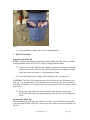
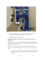
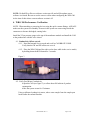
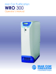
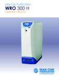
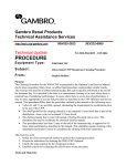
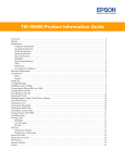
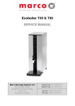
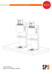
®
Gambro Renal Products
Technical Assistance Services
http://tech.usa-gambro.com
800/525-2623
Technical Update
303/232-6800
WATER,PR,10090 – 12/2009
PROCEDURE
Equipment Type:
WRO 300
Subject:
Updated Installation Procedure
From:
Richard Homol
A new installation procedure and checklist have been released for the WRO300.
Along with the procedure, the installation kit has also changed. The procedure
and checklist are attached.
In the past, installation kits were shipped with a pressure regulator. The pressure
regulator has been replaced with the Gambro flow regulator, WTW522001001.
The flow regulator should be installed when the operating pressure is greater
then 30 psi. It is not required at facilities where the operating pressure falls below
30 psi., but the device should be left with the customer for future use.
There have also been changes to the conductivity calibration, according to the
new service manual, WTHCEN12073.
Other minor content changes have been made in anticipation of changes to the
pretreatment components.
Please refer to Table 2, Tools List, to make sure you have all the necessary tools
to perform the installation.
If you have any questions, please call Technical Support at 1-800-525-2623.
________________________________________________________________________
Rev. A
FORM #. TAA.FRM.0042
Effective.10.08.2008
WRO 300 Installation Procedure
WT300INST01 Rev. A
Page 1 of 10
Introduction
This document provides instructions for completion of the WRO 300 installation. Steps
are numbered to correspond with the installation checklist, WT300INSTLIST. This
procedure must be used in conjunction with the WRO 300 Installation Guide
HCEN12115 (provided by the manufacturer and shipped with the WRO 300); the WRO
300 Service Manual, WTHCEN12073; the installation kit, WT300INSTKIT01, that is
shipped with the WRO 300 in a separate box; and GXP with the latest version of the
defaultUSxp file.
The WRO 300 Installation Guide provides information on WRO 300 setup and hose
connections, as well as information on STARTUP after installation.
The WRO 300 Service Manual provides valuable information regarding internal menus,
screen navigation, service pass codes and performance verifications.
WT300INSTKIT01 provides the parts necessary to complete the installation. Parts
included in the kit are listed in Table 1.
It will be necessary to use GXP and a computer to configure the WRO 300.
Some of the parameters cannot be changed in the internal menu. See Tech Update Water
PR10081, or current Technical Update. The defaultUSxp file will allow the technician to
configure all the machines properly and quickly. Also, certain values will need to be
configured to clinic specific settings. You must use this program to properly complete the
installation.
Table 1 Parts List,
Vendor Part #
WT300CAD
WT300HOSE
WTW522001001
K12755001
WT109133
9801-RTAG
9801-YTAG
WT300INSTLIST
WT300INST01
N/A
N/A
0500-092
0882-113
0883-113
0950-004
0766-315
WT300INSTKIT01
QTY
Item Description
1 ea
1 ea
1 ea
1 ea
1ea
1 ea
1 ea
1 ea
1 ea
4 ea
4 ea
10 in
2 ea
2 ea
8 ea
1
Collect Assist Device
Hose Assy for connecting WRO 300 to Dialysis Machine
Flow Regulator
Tube Removal Tool
Power Cord
Tag, Red Disinfect with Chain
Tag, Yellow Preservative with Chain
Installation Checklist
Installation Procedure
Bolt, Hex, SS, M6 x 25mm
Washer, Spring Lock, SS, M6
Tubing, Clear Vinyl
HFC Hose Barb Insert, Polypropylene, 3/8” Hose Shutoff
HFC Hose Barb Body, Polypropylene, 3/8” Hose Straight Thru
Hose Clamp
Hose Adaptor, 3/8 barb x FGHT
WT300INST01 Rev. A
Page 2 of 10
Tools Required
The tools listed in table 2 are needed to install the WRO 300.
The use of GXP is required to complete proper installation.
Table 2
Tools List
Description
Part #
Torx screwdrivers T-10, T-20, & T-25
Not applicable
100psi test fixture, Pressure-Flow measurement tool
WT100TEST
Installation Guide, shipped with WRO 300
HCEN12115
25 bar pressure gauge
WT2510159
Quick Disconnect for RO Module
WTW507024001
Tube Removal Tool, supplied in Installation Kit
PC interface cable - Logging lead
K12755001
WTK18401001
PC cable adapter USB to serial adapter (If needed)
GXP Software with current defaultUS.xp files
Refer to Tech Update Water PR10056 and Water PR10081
Service Manual
Tech Update Vinegar Cleaning (if needed)
Tech Update Integrated Chemical Disinfection (if needed)
Not Applicable
Can be downloaded from our website at
tech.usa-gambro.com
WTHCEN12073
Water PR10075
Water PR10073R
Tube cutting tool
N/A
Measuring Tape, 10 ft.
N/A
Procedure
1. Assemble Gambro Cart and Prefilter Kits
1.1. Assemble the cart and install the pretreatment kits according to the instructions
provided.
NOTE: If an alternative non-Gambro pretreatment system is to be used, it is the
responsibility of the customer to make sure all local, state, and federal regulations are
followed. Use the quick-connect fittings, provided in the Installation Kit to attach the
pretreatment assembly to the WRO 300. Use the quick-connect, valve stem, on the hose
coming from the pretreatment components. See figure 1
NOTE: If the SS Accessory Box is to be installed, perform all of the Pretreatment and
WRO 300 installation steps and mount the WRO 300 to the cart before attaching the SS
Box. It is difficult to remove the cover of the WRO 300 after the box is installed.
NOTE: The use of carbon tanks will necessitate the installation of particle filtration
between the tanks and the inlet of the WRO 300. A 10” 5 micron filter is recommended.
WT300INST01 Rev. A
Page 3 of 10
Figure 1
1.2. On the checklist, mark the type of pretreatment installed.
2. WRO 300 Assembly
Unpacking the WRO 300
NOTE: Complete instructions for unpacking and installing the WRO 300 are available
in the Installation Guide, HCEN12115, which is shipped with the WRO.
2.1. Carefully remove the WRO from the shipping container according to instructions
found on the outside of the box and verify that all parts have shipped according
to the chart found in section 1.1 of the Installation Guide.
2.2. Verify that all parts have shipped in the Installation Kit. See list above.
CAUTION! The WRO 300 contains a preservative which may cause irritation to eyes,
skin, etc. The internal sections of the machine may be under pressure due to altitude or
atmospheric conditions. Use caution when removing the plugs to prevent contact with the
preservative.
2.3. Remove the plugs from the back of the WRO using the tube removal tool
(K12215001) provided in the Installation Kit. See section 1.3 of the Installation
Guide.
Mounting the WRO 300
When mounting the WRO onto the Gambro cart make sure the WRO 300 is oriented in
such a way that the back of the RO is on the same side of the cart as the cord handle. See
Figure 2.
WT300INST01 Rev. A
Page 4 of 10
Figure 2
2.4. From underneath the cart base, use the four M6 bolts and lock washers to
connect to the mounting holes in the bottom of the WRO 300.
2.5. Installation of Tubing and Product Loop
MAKE ALL TUBING CONNECTIONS USING THE HOSE CLAMPS
PROVIDED.
NOTE: Be certain to use the proper size clamps when attaching the tubing to the
WRO 300. The 6 ½ ft, ¼ in. ID tubing, 11mm hose clamps and smaller sized elbows
are used for the product loop.
NOTE: Italized wording refer to specific steps found in the Installation Guide,
Section 1.3.2 Using the tubing provided, cut to appropriate length as described
below.
2.5.1. Feed Water Inlet: Cut the feed line 3 ft long and attach a QC Body to one
end of the hose, then connect it to the output connector of the pretreatment
component.
WT300INST01 Rev. A
Page 5 of 10
NOTE: Attach the QC Valve Stem to the outlet of the pretreatment line if
needed, then connect the hoses together.
2.5.2. Use an angled connector and clamp and attach the feed line to the back of
the WRO 300 as shown in figure 1.5 of the Installation Guide
2.5.3. Product water outlet and return: Use the supplied 2 meter (6 1/2 ft) hose,
cut it slightly off-center and attach the Y coupling.
2.5.4. Attach the 2 smaller angled connectors and attach to the WRO 300 as
shown in figure 1.6 of the Installation Guide.
2.5.5. Drain Outlet: Cut the drain line in two parts. 1 part should be 1 ft long
and attached to the WRO 300 using the angled connector.
Attach the QC Valve Stem to the opened end of the hose.
Cut the other part 8 ft. long.
Attach the QC Body to one end of the hose and connect the hoses together.
See figure 2 above.
2.5.6. Tank air vent: Use the 10 in. clear tubing supplied in the Installation Kit.
2.5.7. Incoming Water Line: Cut a section of hose 9 ft long and attach the hose
adaptor. Connect the opened end of the hose to the input of the pretreatment
system. Use the Quick Connect fittings if available. Connect the other end
to a water source.
Note: The incoming water line may already be installed if the pretreatment was
already assembled.
2.6. Install the power cord Be sure to run the cable underneath the handle.
2.7. Flush Carbon Pretreatment
2.7.1. Disconnect the QC connector from the drain line and attach it to the
output of the first carbon component. Start with the Primary Carbon
Component, then do the Secondary Carbon Component if installed.
NOTE: If Gambro QC connectors have not been used on the pretreatment, it will
be necessary to flush the carbon components using what ever method that may be
available.
NOTE: It is essential that the carbon be properly rinsed prior to starting the WRO
300. Carbon fines (carbon dust) present in new carbon filters and tanks can
damage the RO membrane and pump if not properly rinsed out prior to use.
WT300INST01 Rev. A
Page 6 of 10
2.7.2. Connect the water line to a water source and open the water valve partially
to slowly purge the air from the pretreatment assembly.
2.7.3. Open the inlet water valve fully and allow the system to flush properly.
Black carbon fines will be observed at the drain. Allow carbon tanks to flush
for 5 minutes after the drain line becomes clear. Carbon Filters should be
flushed for an additional 2 minutes after the drain water is clear.
2.7.4. After flushing, turn off the water and proceed to the second carbon
component or return the hoses to their original positions.
3. WRO 300 Rinse
3.1. Follow the instructions for rinsing the WRO 300 provided in section 1.5 of the
Installation Guide.
3.2. During Rinse observe the lowest pressure indicated on the pressure gauge located
just before the RO. This is the Operating Pressure. Record this value on the
checklist.
3.3. If the Operating Pressure is greater then 30 psi it is recommended to install the
flow regulator. Operating pressures above 44 psi will require the installation of
the flow regulator.
3.3.1. At the end of Rinse, close off the water supply and relieve the pressure in
the pretreatment components.
3.3.2. Cut the tubing just below the back handle of the WRO and attach the flow
regulator. See figure 2 above. (The arrow should point to the WRO 300.)
If not installed, this part should be left with the customer in case of future needs.
3.4. During Rinse verify there are no leaks in the pretreatment or in the WRO 300.
Repair any leaks as necessary. Keep checking this throughout the installation to
ensure the system is left leak-free for the customer.
3.5. Rinse Completed. A full rinse must be completed as the machine has been
packed in a preservation and anti-freeze solution.
3.6. Check for complete rinse-out: Refer to 1.5.1 in the Installation Guide.
3.7. Record the Product water conductivity value as shown on the display.
3.8. Configure the WRO 300 using GXP. Follow the procedure according to Tech
Update, Water PR10081 or the current Technical Update. Use the defaultUS.xp
file to properly configure the WRO 300. Make any clinic specific changes as
required.
WT300INST01 Rev. A
Page 7 of 10
NOTE: DefaultUS.xp files are software version specific and will be update as new
software is released. Be sure to use the correct version when configuring the WRO 300.
At the time of this release current software version is 4.2
4. WRO 300 Performance Verification
NOTE: When attaching or removing devices using the quick connect fittings, ALWAYS
make sure the system is in Standby. Pressure in the system can cause orings inside the
connectors to become dislodged, causing leaks.
Install the 25 bar pressure gauge to the top of the membrane module and install the CAD
to the product line with the valve closed.
4.1. Conductivity Offsets set to 0.
4.1.1. Enter the Internal Service mode and scroll to CALIBRATE COND.
Verify that the FW and PW offsets are set to 0.
4.1.2. Place the WRO 300 into Run. (this can be done while in the service mode)
by holding down the RUN button for 3 seconds.
Figure 3
4.2. Verify Feed Water Conductivity
Adjust the CAD (see figure 3), to allow about 500 ml/min of product
consumption.
Allow the system to run for 15 minutes.
Using a calibrated conductivity meter, take a water sample from the sample port
located after the carbon filtration.
WT300INST01 Rev. A
Page 8 of 10
Compare the reading to the temperature compensated value (T) on the display.
The values should be within 10% or 10 uS, whichever is greater of each other.
Adjust the COEFF as needed.
4.2.1. Record the COEFF value
4.2.2. Record the conductivity value.
4.3. Verify Product Water Conductivity.
Using a calibrated conductivity meter, take a water sample from the end of the
product loop using the CAD.
Compare the reading to the display on the WRO 300.
The values should be within 10% or 1uS, whichever is greater of each other
Adjust the COEFF as needed
4.3.1. Record the COEFF value
4.3.2. Record the conductivity value.
4.4. Verify Product Pressure and Flow. Refer to the Service Manual, section 6.4 for
information on adjusting the flow and pressure. Flow should be 1200 + 100
ml/min., with a loop pressure between 22 to 30 psi. Measure the flow for at least
30 seconds
4.4.1. Record the loop pressure
4.4.2. Record flow rate
4.5. Verify the Reject Pressure is less then 13 bar (190psi.). Record the value
4.6. Verify Proper Operation of the Chemical Pump.
Using water for testing, initiate a Minncare Disinfection procedure and verify 50 ml
of volume uptake (+ 20 % ).
4.6.1. Put 100 ml of water into a graduated cylinder.
4.6.2. Insert the disinfect wand into the front of the WRO 300 and
place the other end in the graduated cylinder
4.6.3. Use the arrow keys to select Minncare
4.6.4. Initiate the chemical disinfection buy pressing DIS
4.6.5. The WRO 300 will enter the chemical intake phase.
4.6.6. Verify the WRO 300 pulled in 50 ml (+ 10ml)
4.6.7. Record the volume.
WT300INST01 Rev. A
Page 9 of 10
4.7. Clear the Rinse Flag using Internal Service
4.7.1. Enter Internal Service following the procedure listed in section 2.7 of the
Service Manual.
4.7.2. Scroll to Clear Chem Flag and confirm.
4.7.3. Set CHEM FLAG to False using one of the arrow keys and confirm.
4.7.4. Exit the Internal Service mode by pressing the DIS button 3 times.
4.7.5. Cycle power using the power switch at the back of the machine.
Upon power up, the system should return to Standby.
4.8. Verify Leakage Current is less then 145 uA and record the value.
4.9. Verify Ground Resistance is less then 0.3 Ohms and record the value.
4.10. Install the SS Lock Box, if provided. Be sure the one way bolt heads are
facing to the outside of the box (Mark N/A if the Lock Box is not installed.)
4.11. Advise Customer that AAMI analysis for Chemical and Bacterial Contaminants
is required prior to use.
WT300INST01 Rev. A
Page 10 of 10
WRO 300 INSTALLATION CHECKLIST
EQUIPMENT LOCATION_____________________
SERVICE DATE(S) _______________________________
SERIAL NUMBER___________________________
WORK ORDER__________________________________
MACHINE HOURS___________________________ TECHNICIAN: ___________________________________
A checkmark or a “X” indicates the step is completed or function is within the specifications listed on the checklist, procedure or
Service Manual. Record values where units are given.
1.
2.
3.
4.
ASSEMBLY OF GAMBRO CART AND PRETREATMENT KITS.
1.1. Gambro CART and pretreatment Kits assembled and installed per instructions.
(Mark N/A is a non-Gambro pretreatment system is used)
1.2. Type of pretreatment installed:
1.2.1. Carbon Filter
1.2.2. Dual Carbon Filters
1.2.3. Carbon Tank w Carbon Filter
1.2.4. Dual Carbon Tanks
1.2.5. Other
________
________
________
________
________
WRO 300 ASSEMBLY
2.1. Remove WRO from the shipping container and verify all parts have been supplied
2.2. Verify all parts have shipped in Installation Kit content
2.3. Remove plugs from back of WRO 300
2.4. Mount the WRO 300 to the Gambro Cart. (Mark N/A if non-Gambro cart was used)
2.5. Hoses attached to the WRO 300 per Installation Guide and Installation Procedure
2.6. Power cord installed
2.7. Carbon Components Properly Flushed
________
________
________
________
________
________
________
WRO 300 RINSE
3.1. Initiate Rinse
3.2. Record Operating Pressure
3.3. Install Flow Regulator (Mark N/A if the flow regulator is not installed)
3.4. Check pretreatment and WRO for leaks
3.5. Rinse completed. Refer to section 1.5 of the installation guide.
3.6. Check for complete rinse out per Installation Guide 1.5.1
3.7. Record product water conductivity
3.8. Configure the WRO 300 using GXP and the current defaultUS.xp file
________
________ psi
________
________
________
________
________ uS
________
WRO 300 PERFORMANCE VERIFICATION
4.1. Conductivity Offsets set to zero
4.2. Verify feed water conductivity
4.2.1. Record the COEFF
4.2.2. Record conductivity value
4.3. Verify product water conductivity
4.3.1. Record the COEFF
4.3.2. Record conductivity value
4.4. Verify product pressure and flow
4.4.1. Record pressure setting
4.4.2. Record flow rate
4.5. Verify reject pressure is less than 13 Bar (190 psi) Record the pressure
4.6. Verify proper operation of the chemical pump and record the uptake volume
4.7. Clear rinse flag using Internal Service
4.8. Verify leakage current does not exceed specification of 145 uS Record value
4.9. Verify ground resistance is below 0.3 ohms Record value
4.10. Install SS lock box (if provided) (Mark N/A if the lock box is not installed)
4.11. Advise user that AAMI analysis for Chemical and Bacterial contaminates is required
________
________
________
________ uS
________
________
________ uS
________
________ psi
________ l/min
________ psi
________ ml
________
________ uA
________
________
________
________
Part Number: WT300INSTLIST REV: C