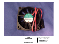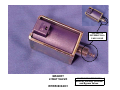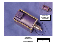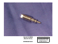
1
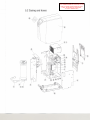
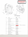
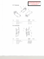
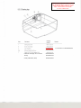
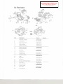
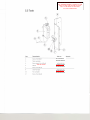
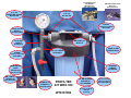
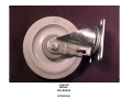
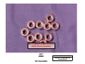
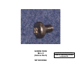
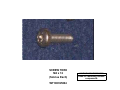
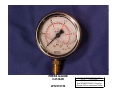
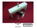
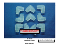
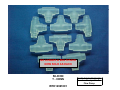
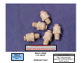
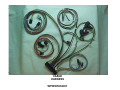
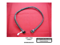
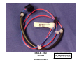
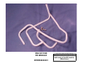
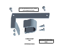
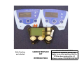
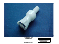
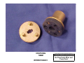
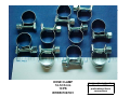
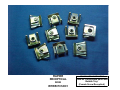
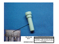
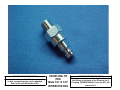
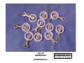
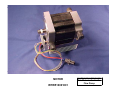
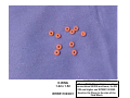
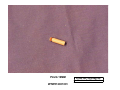
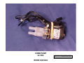
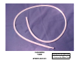
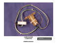
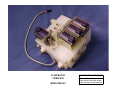
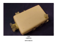
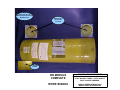
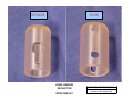
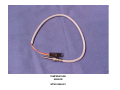
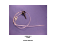
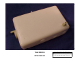
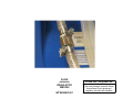
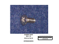
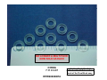
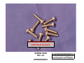
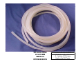
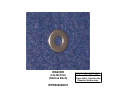
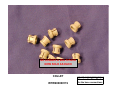
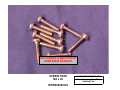
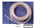
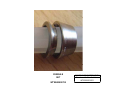
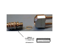
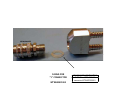
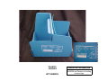
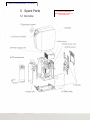
LAST UPDATED SEPT 16, 2010
5 SpareParts
5.1 Overview
CLICK ON A MODULE
DESCRIPTION TO GO TO
THAT MODULE
7.0perator's panel
6.Chemical intake
4.Flow block
3.Flow pump unit
2.Power supply unit
9.CPU board
B.RO-membrane
5.Tank unit
10. EMC plate
...
._-"
5.2 Casingandhoses
CLICK ON EITHER THE PART NUMBER OR
THE "NUMBER BUBBLE" POINTING AT THE
PART TO VIEW THE PICTURE OF THAT
PART. TO RETURN TO THIS PAGE,
"ALT,LEFT ARROW KEY"
65
CLICK ON EITHER THE PART NUMBER OR
THE "NUMBER BUBBLE" POINTING AT THE
PART TO VIEW THE PICTURE OF THAT
PART. TO RETURN TO THIS PAGE,
"ALT,LEFT ARROW KEY"
EARJH
Ordering
number
Item
Partname
4
Screw M4x12 TORX
W504010 001
WT100395004
6
Screw Torx M4x8
9
Screw Torx M5x20
W504 009 001
WT100395002
W504 012 001
10
Locking nut M5
W504 002 001
12
Power supply unitw
WTW502003006
15
SiliconeT-connector
W507 014001
WTK1296001
16-24
Pex pipe kit
W514 002 001
25,26
Siliconehose di6xt3 mm (5 metre)
W518 002 001
29
Nut M6M4
WT100390400
W504 003 001
33
Detachable cover
W501 002 001
50
CPU Board For SW 4.2 and Lower
W502 001 001
WTW502001003
51
Clip, PCB complete
W508 001 001
52
Overlay,WRO 300
W503 001 001
57
Screw Plastic Torx T30x8
W504 005 001
WT100366308
59
Siliconehose di5x1.5 mm (10 metre)
W518 003 001
65
Quarter turn screw
66
Cable harness WRO 300
W505 002 001
67
Cable CPU PCB to Ext Com.
W505 003 001
W504 007 001
WTW900000109
68
Externalcommunication Board, complete
W502 002 001
72
Screw Torx M4x10
W504 011 001
73
Locking nut M4
75
Screw Plastic Torx K50x12
W504 001 001
WT100316046
W504 006 001
WT100365003
88
Cable CPU PCB to Fan
W505 004 001
TPL-plug 5/16"
W507 016 001
WTW200148001
WTW506008001
90
Filter Kit Air Power Supply
Remark
For SW 4.3 use WTW502001004
5.2.1
Casingtray
CLICK ON EITHER THE PART NUMBER OR
THE "NUMBER BUBBLE" POINTING AT THE
PART TO VIEW THE PICTURE OF THAT
PART. TO RETURN TO THIS PAGE,
"ALT,LEFT ARROW KEY"
-i
Partname
Ordering
number
Casing tray
W501 004 001
2
Rapier Receptacle4 mm
W507 012 001
3
Rubberfoot
W501 008 001
Item
Remark
5.2.2 Casingback
Partname
Ordering
number
Casing back mould
W501 001 001
2
Rapier Receptacle4 mm
W507 012 001
4
Screw M8x16
W504
014 001
WTW900000103
5
Nut M6M8
W504
004 001
WT100390800
Item
Remark
CLICK ON EITHER THE PART NUMBER OR
THE "NUMBER BUBBLE" POINTING AT THE
PART TO VIEW THE PICTURE OF THAT
PART. TO RETURN TO THIS PAGE,
"ALT,LEFT ARROW KEY"
5.2.3 Casing top
Partname
Ordering
number
Casingtop cover
WS01003 001
3
Screw Torx M4x8
WS04009 001
4
User interface
WS02004 001
WTW506015001
S,6
Siliconehose di3xt12mm
7
CableCPU PCB to DisplayPCB
WS18003 001
WTW900000261
WSOS001 001
Cable CPU to Display SW 4.3 version
WTW505001002
Overlay
WTW503001001
Overlay WRO300H (Heat)
WTW503002001
Item
Remark
For SW version 4.3 WTW506015002
CLICK ON EITHER THE PART NUMBER OR
THE "NUMBER BUBBLE" POINTING AT THE
PART TO VIEW THE PICTURE OF THAT
PART. TO RETURN TO THIS PAGE,
"ALT,LEFT ARROW KEY"
J
5.3 Flow
pumpunit
Item
Denomination
Orderno
2
Motor
W510001 001
3
Coupling 14 mm
W507 006 001
5
Pump
W513 002 001
WTW513002002
8
Screw Torx M6x8
W504 013 001
9
Screw M4x12
W504 010 001
WT100395004
Remarks
CLICK ON EITHER THE PART NUMBER OR
THE "NUMBER BUBBLE" POINTING AT THE
PART TO VIEW THE PICTURE OF THAT
PART. TO RETURN TO THIS PAGE,
"ALT,LEFT ARROW KEY"
5.4 Flowblock
t-
I6ET
B'MSS
Item
Denomination
Orderno
Flow block, complete
W515 003 001
8
a-ring 4.3x2.4
W511 006001
WT100319022
9
Male connector T1/1"
W507 009 001
10
Valve membrane
W509 001 001
11
Magnet 2-way valve
W508 004 001
12
Magnet 3-way valve
W508 005 001
13
Spring TFO.25x3x20
W508
009 001
WTW900000072
14
Valve screw
W508 010 001
15
a-ring 5.1x1.6
W511 007 001
WT100319023
18
Conductivity cell
W508 002 001
19
Temperature sensor
W516 004 001
20
Collet
W507
002 001
WTW900000119
21
Plug 19 mm
W512 001 001
22
Plug 30 mm
W512 002 001
23
a-ring 7.1x1.6 Flourine rubber
W511 003001
24
Screw M4x12
W504 008 001
WT100370412
25
Screw Torx M4x8
W504 009 001
26
a-ring 7.11 x2.87
W511 012001
WTW900000052
27
Screw M3x6
W504 016 001
28
a-ring 2.57x1. 78
W511
011 001
WT100319060
Remarks
CLICK ON EITHER THE PART NUMBER OR
THE "NUMBER BUBBLE" POINTING AT THE
PART TO VIEW THE PICTURE OF THAT
PART. TO RETURN TO THIS PAGE,
"ALT,LEFT ARROW KEY"
5.5 Tank
Item
Denomination
2
Orderno
Remarks
Screw Torx M4x8
W504
009 001
WT100395002
3
Tank, complete
W515 004 001
WTW515004002
4
Screw plastic Torx K50x12
W504 006 001
5
SiliconeT-connector
ANGLED CONN
W507
014 001
WTW507013001
7
Screw Torx M4x10
W504 011 001
WTW900000050
9
CleanPEXpipe
W514 001 001
20
Fan complete
W508 003 001
WTW508003002
21
Screw Torx M4x20
W504 015 001
WTW900000128
CLICK ON EITHER THE PART NUMBER OR
THE "NUMBER BUBBLE" POINTING AT THE
PART TO VIEW THE PICTURE OF THAT
PART. TO RETURN TO THIS PAGE,
"ALT,LEFT ARROW KEY"
Item
Denomination
Tank
Orderno
Remarks
W519 001 001
WTW519001002
W511 008001
WT100319029
2
O-ring 15.3x2.4
3
Level sensor
W516 002001
4
Screw Plastic TorxT30x8
W504 005 001
5
Spray nozzle
W508 007 001
6
O-ring 8.3x2.4
7
Connector safety strip
W511
009 001
WT100319032
W507 004 001
8
SiliconeT-connector
ANGLED CONN
W507
014 001
WTW507013001
9
Tank overflow AIR VENT
W508
006 001
WTW508006002
10
Level sensor deflector
W516 003 001
Float Level Switch (Mechanical)
WTW508013002
5.6 Chemicalintake
Item
4
CLICK ON EITHER THE PART NUMBER OR
THE "NUMBER BUBBLE" POINTING AT THE
PART TO VIEW THE PICTURE OF THAT
PART. TO RETURN TO THIS PAGE,
"ALT,LEFT ARROW KEY"
Denomination
Orderno
Remarks
Chemical intake, complete
W515
002 001
WTW515002002
O-ring. 10.1 x1.6
W511
005001
WT100319020
5
Spring TF1x6x25
W508
008 001
WTW900000072
8
Screw Torx M4x10
W504
011 001
WTW900000050
11
Screw Torx M4x8
W504 009 001
WT100395002
12
Chemical pump 24 V AC
W513
001 001
WTW513001002
13
Cable Optical sensor
W516 001 001
18
a-ring 5.3x2.4
W511
010001
WT100319039
19
Washer 4.3x12x1
W504
018 001
WTW900000070
21
Nipple angled 5/16"
STRAIGHT NIPPLE
Chemical Pump Mounting Kit (not shown)
W507
011 001
WTW507010001
WTW506010003
CLICK ON EITHER THE PART NUMBER OR
THE "NUMBER BUBBLE" POINTING AT THE
PART TO VIEW THE PICTURE OF THAT
PART. TO RETURN TO THIS PAGE,
"ALT,LEFT ARROW KEY"
5.7 RD-module
Item
Denomination
Orderno
RO module, complete
W515
001 001
WTW515008002
2
Gable in (Old style with Black fittings)
W501 005 001
3
O-ring 107.32x5.34
W511 002001
WT100318085
4
Lock
washer
Holding
Plate
W501 007 001
WTK09494001
5
ScrewM5x10
W504
019 001
WT100374510
6
Connector anglejoint Black Fitting
W507 001 001
7
O-ring 5/16"
W511
013001
WT100335001
8
Locking ring 5/16"
W507
008 001
WT100335002
11
Connector straight
13
Gable out Old style with Black fittings
14
O-ring 10.5x1.6
Black
W511 001 001
16
O-ring 7.1x1.6
Clear
W511 004 001
WT100319004
17
Membrane kit
Black Fitting
Remarks
W507 003 001
W501 006 001
W506 001 001
WTK10640001
New style WTW515009001
Incl.
Membrane,3,
14,16 and
spacer
Male Connector T12/1 P5/16"
WTW100111001
Cream colored connector on the end cap of the RO Module
O-Ring 13.3 x 2.4
for connector WTW100111001
WT100319033
Male QD Coupling 1/8"
WTW507021002
QD connector on end cap of RO Module for checking Membrane pressure
PEX Kit for RO Module
WTW506003001
If Changing RO Module from old style with the black fittings to the new style
with the cream colored connectors, this kit must also be ordered
CLICK ON EITHER THE PART NUMBER OR
THE "NUMBER BUBBLE" POINTING AT THE
PART TO VIEW THE PICTURE OF THAT
PART. TO RETURN TO THIS PAGE,
"ALT,LEFT ARROW KEY"
5.8 Packinglist
Item
Denomination
Orderno
Remarks
Disinfectiontube
WS18 001 001
2
Reinforced tube 8/14"
WS18
004 001
WTK03343A
3
Mains cable
WSOS007 001
WT109133
4
Hose clamp 14 - 12.S mm
WS07 007 001
S
Nipple angled S/16"
WS07 011 001
WTW200304001
6
Y-connector 1.0x8 mm
WS07
016 001
WTW507022001
7
Female
for "Y" conn.
CouplingConnector
body 1/4 1.0x8mm
WS07
OOS001
WTW900000797
7
Coupling insert 1/4 1.0x8 mm
O-Ring for "Y" conn.
WS07 017 001
WTW900001062
Pretreatment, Reject, Overflow Lines
5.9 Accessories
Item
Denomination
Orderno
Withdrawing tool
WTK12215001
WS17 003 001
Connector tool
WS17 001 001
Tube cutter, PEX
WS17 002 001
Remarks
Pressure manometer
External Cable, Remote WRO 300- AK 9S
WSOS010 001
External Cable, Remote WRO 300- AK 100
WSOS008 001
External
Service Cable,
ManualRemote WRO 300- AK 200
WSOS009 001
WTHCEN12073-09/0
WSOS006 001
WTK18401001
External Cable, Logging
QD, Male, 3/8", Pretreatment Part
WT0882113
Castor, Swivel, W/O Brake
QD, Female, 3/8", Pretreatment Part
WT0883113
Castor, Swivel, W/Brake
Gauge, 100 PSI Test Fixture
WT100TEST
1/4" "T" Fitting, Pretreatment Part
Pipe Nipple, 1/4" x Close, Pretreatment Part
1/4" Sample Port
Service Manual, 3.2 Software
Coupling to PEX Male 1/4" x 1/8"
Coupling for Gauge
Prefilter Kit WRO 300
Hose Assy
CAD (Collection Assist Device)
Help Cards
WT0353990BRAKE
Pressure Regulator Kit
WT6179601
WT3805002
Flow Regulator, External
WTW522001001
WT3861037
Float Level Switch
WTW508013001
WT5309102
Pressure Gauge, 0 - 25 Bar / 300 PSI
WT0353990
WT2510159
WTHCEN12073
WTW507021002
WTW507024001
WT6187002
WT300HOSE
WT300CAD
WTWRO300HELPCARDS
Silicon Tubing 15mm OD x 9mm ID, 1M length WT100312093
Used for the Product and Return lines
If longer than 1 meter lines are desired use WTW900000261 and
2 - WTW200304001 5/16" Angled Nipples
Hitch Kit to hook to Phoenix
Plastic Jug Box
WT6184000
WTCHEMBOX
Guage, 300 PSI Test Fixture
WT300PSITEST
Nipple, Angled 5/16 - 1/4
WTW200303001
Hose Clamp 11mm
for WTW507027001 Angled Nipples
WTW504021001
Sound Lowering Kit
WTW506014001
KIT INCLUDES THE FOLLOWING;
Pex Pipe Kit
WTW514005001
Needle Valve Complete
WTW521001001
Flow Regulator Complete
WTW100224001
Fan Control Board
WTW502008001
Cable CPU-Fan Control Board WTW300140001
Cable Fan Control Board-Fan
WTW300141001
Ferrule Set to Needle Valve
WTW900000725
FLOW REGULATOR
FOR WRO300
WTW522001001
NOT PART OF KIT
PRESSURE REGULATOR
WT6179601
NOT PART OF KIT
REDUCER
1 TO 1/4
WT3839128
0 to 100
PRESSURE GAUGE
WT5335100
ELBOW
1/4MNPT X 5/16 BARB
WTL45NN
1/4 SS CLOSE
NIPPLE
WT9801316NIP
1/4 CLOSE
NIPPLE
WT3861037
BRACKET KIT
WTS7577
HOSE CLAMP
WTW507007001
TEE 1/4 THREAD
WT3805002
ELBOW
1/4MNPT X 5/16 BARB
WTL45NN
HOUSING
O-RING
WT6800905
REINFORCED
HOSE
WTK03343A
Not part of Kit
QD, FEM 3/8"
WT0883113
Not part of Kit
QD MALE 3/8"
WT0882113
Not part of Kit
PREFILTER
KIT WRO 300
WT6187002
10" BB HOUSING
WT6802010
NOT SPARED
FILTER HOUSING
WRENCH
WTS7594P
Replacement filter
10"Carbon/.5 Micron
WT01425125975
CASTOR
SWIVEL,
W/O BRAKE
WT0353990
CASTOR
SWIVEL,
WITH BRAKE
WT0353990BRAKE
QD MALE 3/8"
WT0882113
SPARE PART INFORMATION
WT0882113 is part of the
pretreatment.
QD MALE 3/8"
WT0883113
SPARE PART INFORMATION
Used on the Pretreatment
Assy
SILICONE
TUBING
WT100312093
SPARE PART INFORMATION
Used on the Product and Return Lines.
15mm OD x 12mm ID x 1 Meter in
length, if longer lines are desired use
WTW900000261 (5 meter length)
LOCKING NUT
M4
(Sold as Each)
WT100316046
SPARE PART INFORMATION
Used for mounting the Flow
Pump Unit
O-RING
107.32 x 5.34
WT100318085
SPARE PART INFORMATION
107.32 mm ID X 5.34 mm
thickness. Used on both RO
Gables, (End Caps)
NO LONGER A MULTI PACK
NOW SOLD AS EACH
O-RING
7.1 x 1.6
WT100319004
SPARE PART INFORMATION
7.1 mm ID X 1.6 mm thickness.
Used on the product water fitting
on the RO Membrane
NO LONGER A MULTI PACK
NOW SOLD AS EACH
O-RING
1.42 X 1.52
WT100319010
SPARE PART INFORMATION
1.42mm ID X 1.52mm
thickness. Used on the
Plugs in the Flow Block.
NO LONGER A MULTI PACK
NOW SOLD AS EACH
O-RING
10.1 x 1.6
WT100319020
SPARE PART INFORMATION
Used on “Spring TF1”,
WTW900000072 which is part
of the chemical intake assy.
NO LONGER A MULTI PACK
NOW SOLD AS EACH
O-RING
4.3 x 2.4
WT100319022
SPARE PART INFORMATION
4.3 mm ID X 2.4 mm thickness. Used
on the the male fitting
WTW100111001 on the Flow Block
NO LONGER A MULTI PACK
NOW SOLD AS EACH
O-RING
5.1 X 1.6
WT100319023
SPARE PART INFORMATION
5.1 mm ID x 1.6 mm
thickness. Used on the
Valve Screw, (Needle Valve)
on the flow block
NO LONGER A MULTI PACK
NOW SOLD AS EACH
O-RING
15.3 X 2.4
WT100319029
SPARE PART INFORMATION
15.3 mm ID x 2.4 mm
thickness. Used on the
Level Sensors
NO LONGER A MULTI PACK
NOW SOLD AS EACH
O-RING
8.3 X 2.4
WT100319032
SPARE PART INFORMATION
8.3 mm ID x 2.4 mm thickness.
Used on the Spray Nozzle on
top of the water tank
NO LONGER A MULTI PACK
NOW SOLD AS EACH
O-RING
5.3 X 2.4
WT100319039
SPARE PART INFORMATION
5.3 mm ID x 2.4 mm
thickness. Used on the
Chemical Intake assy and the
Disinfect uptake tube
NO LONGER A MULTI PACK
NOW SOLD AS EACH
O-RING
2.57 X 1.78
WT100319060
SPARE PART INFORMATION
2.57 mm ID x 1.78 mm
thickness. Used on the
Temperature Sensors
NO LONGER A MULTI PACK
NOW SOLD AS EACH
O RING
5/16"
WT100335001
SPARE PART INFORMATION
Used in the compression fittings on
each end of the Membrane housing
NO LONGER A MULTI PACK
NOW SOLD AS EACH
LOCKING RING
5/16"
WT100335002
SPARE PART INFORMATION
Used on both ends of the old style
RO Module with the black fittings,
included in PNs WTW507001001 and
WTW507003001
NO LONGER A MULTI PACK
NOW SOLD AS EACH
SCREW TORX
K50 x 12
WT100365003
SPARE PART INFORMATION
Used for mounting the Plastic Pex
Tubing bracket to the side of the
water tank, (above the level sensors)
NO LONGER A MULTI PACK
NOW SOLD AS EACH
SCREW TORX
T30 x 8
WT100366308
SPARE PART INFORMATION
Used for mounting the Plastic
Shield to the water tank that
protects the power supply
NO LONGER A MULTI PACK
NOW SOLD AS EACH
SCREW
M4x12
WT100370412
SPARE PART INFORMATION
Used for assembling the 2
halves of the Flow Block.
NO LONGER A MULTI PACK
NOW SOLD AS EACH
SCREW
M5 X 10
WT100374510
SPARE PART INFORMATION
Used on the Holding
Plates for the Old style
RO Module End Caps
NO LONGER A MULTI PACK
NOW SOLD AS EACH
SCREW
M5 X 10
WT100374510
SPARE PART INFORMATION
Used on the Holding
Plates for the Old style
RO Module End Caps
NO LONGER A MULTI PACK
NOW SOLD AS EACH
NUT
M6M4
WT100390400
SPARE PART INFORMATION
Used for attaching the Power
Supply Earth Ground to the frame
NO LONGER A MULTI PACK
NOW SOLD AS EACH
NUT
M6M8
WT100390800
SPARE PART INFORMATION
Used for mounting the
Casing Back
SCREW TORX
M4 x 8
(Sold as Each)
WT100395002
SPARE PART INFORMATION
Used for mounting various
components
SCREW TORX
M4 x 12
(Sold as Each)
WT100395004
SPARE PART INFORMATION
Used for mounting various
components
TUBE CUTTER
SPARE PART INFORMATION
WT100830012
For cutting Pex tubing
PRESS GAUGE
0-25 BAR
WT2510159
SPARE PART INFORMATION
25 Bar = 362.5PSI
Use WTW507024001 Coupling,
(Female QD) to create test fixture
CAD ASSY
WT300CAD
SPARE PART INFORMATION
Collection Assist Device
HOSE ASSY
WT300HOSE
SPARE PART INFORMATION
The QD end plugs into the “Y”
connector, WTW507022001
300 PSI TEST
FIXTURE
WT300PSITEST
SPARE PART INFORMATION
Used for checking the Reject
Pressure on the RO Module after
setting the Needle Valve
1/4 “ FITTING
WT3805002
SPARE PART INFORMATION
Used on Pretreatment and
some PSI test fixtures.
PIPE NIPPLE
1/4“ CLOSE
WT3861037
SPARE PART INFORMATION
Used on Pretreatment and
some PSI test fixtures.
1/4“ SAMPLE
PORT
WT5309102
SPARE PART INFORMATION
Used on Pretreatment,
some PSI test fixtures and
WT300CAD
Pressure Regulator
Kit
WT6179601
SPARE PART INFORMATION
Needed on the WRO300 if the
feed water pressure is above 44
psi, or use WTW522001001
External Flow Regulator
O-RING
23G BLUE
SLIMLINE
WT6800901
SPARE PART INFORMATION
Used on Blue Slimline Prefilter
Housing
O-RING
BIG BLUE
HOUSING
WT6800905
SPARE PART INFORMATION
Used on Big Blue Filter Housing
SERVICE MANUAL
WTHCEN12073-09/0
100 PSI TEST
FIXTURE
WT100TEST
SPARE PART INFORMATION
Used for setting the Needle
Valve
REINFORCED
TUBE 8/14
WTK03343A
SPARE PART INFORMATION
Used on the Pretreatment,Overflow, and
Reject Lines. 8mm ID x 14mm OD x 10
Meters in length, (33 ft.) For Product and
Return lines use WT100312093
NO LONGER A MULTI PACK
NOW SOLD AS EACH
HOLDING
PLATE
WTK09494001
SPARE PART INFORMATION
Used on the Old style
RO Module end caps
THESE PARTS ARE INCLUDED
WT100318084
K18913-1
NOT SPARED
WT100318085
WT100319004
WTK10640001
MEMBRANE
KIT
SPARE PART INFORMATION
Replacement RO Membrane for
WRO 300, and the WRO 95.
WITHDRAWING
TOOL
WTK12215001
SPARE PART INFORMATION
This is the same tool that is
used on the WRO95
NO LONGER A MULTI PACK
NOW SOLD AS EACH
SILICON
ANGLED CONN.
WTK12951001
SPARE PART INFORMATION
Used on the Water Tank,
NO LONGER A MULTI PACK
NOW SOLD AS EACH
SILICON
T - CONN
WTK12961001
SPARE PART INFORMATION
Used on the input to the
Flow Pump
LOGGING
CABLE
WTK18401001
SPARE PART INFORMATION
For machines SN5996 and lower unless the
CPU has been replaced with the 4.3 software
version CPU.This is the PC interface cable
needed for use with GXP and GXL
ELBOW 1/4"
MNPT X 5/16"
BARBED
WTL45NN
SPARE PART INFORMATION
Used on Pretreatment,
on the input and output hoses.
NO LONGER A MULTI PACK
CONNECTORS ARE NOW SOLD AS EACH
REFER TO
SERVICE
NEWSLETTER
GI011
MALE CONN.
T1/1 P5/16"
WTW100111001
SPARE PART INFORMATION
(SOLD AS EACH)
This is the new style
connector on the end caps of
the RO module
FLOW REGULATOR
WRO300
WTW100224001
SPARE PART INFORMATION
This is part of the Sound Lowering Kit,
WTW506014001, it is not a pressure
regulator. If the inlet pressure exceeds
44 psi, an external Flow (pressure)
regulator should to be installed
WTW522001001
TPL-PLUG
5/16"
WTW200148001
SPARE PART INFORMATION
These are the plugs that are removed at
installation. They should be kept and
stored, they will be used if preservation
is needed
PRODUCT
RETURN
NO LONGER A MULTI PACK
NOW SOLD AS EACH
OLD NIPPLES ARE SHOWN IN PICTURE
NIPPLE ANGLED
5/16-1/4
WTW200303001
SPARE PART INFORMATION
Used on back of machine for
Product and Return hose
connections.
NO LONGER A MULTI PACK
NOW SOLD AS EACH
NIPPLE
ANGLED 5/16"
WTW200304001
SPARE PART INFORMATION
Used on back of machine for
Feed, Reject, and Tank
Overflow hose connections.
CABLE
WRO300
PC-USB
WTW300236001
SPARE PART INFORMATION
Needed for machines SN5997 and
higher or on older machines that the
CPU has been replaced the 4.3
software version CPU WTW502001004
CASING BACK
MOULDED
WTW501001001
SPARE PART INFORMATION
Use screws WTW504009001
for mounting
DETACHABLE
COVER
WTW501002001
SPARE PART INFORMATION
Screws are not needed for
mounting, attaches with
magnets
CASING TOP
COVER
WTW501003001
CASING TRAY
(Bottom Cover)
WTW501004001
SPARE PART INFORMATION
Use screws WTW504011001
for mounting
GABLE IN
(END CAP)
WTW501005001
SPARE PART INFORMATION
This part does not come with
the o-ring (WTW511002001)
GABLE OUT
(END CAP)
WTW501006001
SPARE PART INFORMATION
This part does not come with
the o-ring (WTW511002001)
RUBBER FOOT
WTW501008001
SPARE PART INFORMATION
Used on the Casing Tray
WTW501004001
CPU
BOARD
WTW502001003
WTW502001003R
SPARE PART INFORMATION
For machines SN5996 and lower
unless the CPU has been replaced
with the 4.3 software version CPU.
CPU
WTW502001004
SPARE PART INFORMATION
For machines SN5997 and higher or on
older machines that the CPU has been
replaced with the 4.3 software version
CPU WTW502001004
EXT. COM.
BOARD
COMPLETE
WTW502002001
SPARE PART INFORMATION
The center, (black) port is the
only one used in the US.
POWER
SUPPLY UNIT
WTW502003006
OVERLAY
WTW503001001
SPARE PART INFORMATION
Overlay attaches by an
adhesive backing
OVERLAY
WRO300H
WTW503002001
LOCKING NUT
M4
WTW504001001
SPARE PART INFORMATION
Used for mounting the Flow
Pump Unit
LOCKING NUT
M5
WTW504002001
SPARE PART INFORMATION
Used for attaching the mounting
blocks to the RO Module
SCREW
M3 x 6
WTW504016001
SPARE PART INFORMATION
Used for mounting the
valves on the Flow Block
CABLE - CPU
TO DISPLAY
WTW505001001
SPARE PART INFORMATION
For machines SN5996 and lower unless
the CPU has been replaced with the 4.3
software version CPU. This cable
attaches the display PCB (User
interface) to the CPU
CABLE
CPU TO DISPLAY
(User Interface)
WTW505001002
SPARE PART INFORMATION
Needed for machines SN5997 and
higher or on older machines that the
CPU has been replaced the 4.3
software version CPU WTW502001004
CABLE
HARNESS
WTW505002001
CPU - PCB
CABLE
WTW505003001
SPARE PART INFORMATION
CPU to External
Communications
CABLE - CPU
TO FAN
WTW505004001
SPARE PART INFORMATION
This cable attaches the
Cooling Fan to the CPU
PEX KIT FOR
RO MODULE
WTW506003001
SPARE PART INFORMATION
Not shown in manual, used on
both ends of the RO module,
(Membrane)
FILTER KIT AIR
POWER SUPPLY
WTW506008001
KIT INCLUDES 60cm (23 in) OF TUBING
(NOT SHOWN IN PICTURE)
CHEM PUMP
KIT
WTW506010003
SPARE PART INFORMATION
Refer to Service Newsletter
GI046
WTW503002001
Both Overlays
are included
WTW503001001
USER
INTERFACE
WTW506015001
SPARE PART INFORMATION
For machines SN5996 and lower unless
the CPU has been replaced with the 4.3
software version CPU.
Both Overlays
are included
USER INTERFACE
KIT
WTW506015002
SPARE PART INFORMATION
Needed for machines SN5997 and
higher or on older machines that the
CPU has been replaced the 4.3
software version CPU WTW502001004
CONNECTOR
ANGLE JOINT
WTW507001001
SPARE PART INFORMATION
Used on one end of the
membrane housing
CONNECTOR
STRAIGHT
WTW507003001
SPARE PART INFORMATION
Used on one end of the
membrane housing
CONNECTOR
SAFETY CLIP
WTW507004001
SPARE PART INFORMATION
Used on top of Water Tank to
hold the silicon elbow in place
CONNECTOR
STRAIGHT
WTW507005001
SPARE PART INFORMATION
This part was part of the
original pretreatment kit,
No Longer Used
COUPLING
14MM
WTW507006001
SPARE PART INFORMATION
This is the coupling between
the Flow Pump Motor and
Pump Head
HOSE CLAMP
14-12.5 mm
10 PK
WTW507007001
SPARE PART INFORMATION
Used on all the
pretreatment hose
connections
NIPPLE
STRAIGHT
10PK
WTW507010001
SPARE PART INFORMATION
Used on the bottom of the
Chemical Intake Pump
RAPIER
RECEPTICAL
4mm
WTW507012001
SPARE PART INFORMATION
Used on Casing Back panel and
Bottom Tray.
(Female Screw Receptical)
TPL-PLUG
5/16"
WTW507015001
SPARE PART INFORMATION
These are the plugs that are removed at
installation. They should be kept and
stored, they will be used if preservation
is needed
SPARE PART INFORMATION
Used on the end cap of the Membrane Housing
so that a pressure gauge can be attached.
Refer to Service Newsletter GI011
COUPLING TO
PEX
Male 1/4” X 1/8"
WTW507021002
SPARE PART INFORMATION
This part can be screwed directly into the water
inlet fitting on the back of the Phoenix, the Y
Coupling, (WTW507022001), from the RO, will
connect to it.
O-RING ONLY
WTW900001062
FEMALE
CONNECTOR ONLY
WTW900000797
Y-COUPLING
SS 6MM
WTW507022001
SPARE PART INFORMATION
Used on the Product
Water line
COUPLING
FOR GAUGE
WTW507024001
SPARE PART INFORMATION
Used on Gauges for Test
Fixtures
CLIP PCB
COMPLETE
WTW508001001
SPARE PART INFORMATION
Used to hold the CPU in
place
CONDUCTIVITY
CELL
WTW508002001
SPARE PART INFORMATION
Both Condo Cells are
the same part number
FAN
COMPLETE
WTW508003002
SPARE PART INFORMATION
Interface cable for the
fan to the CPU is
WTW505004001
THIS PART IS
DIFFERENT ON A
3-WAY VALVE
MAGNET
2-WAY VALVE
WTW508004001
SPARE PART INFORMATION
Used for the Inlet, Overflow
and Bypass Valves.
THIS PART IS
DIFFERENT ON A
2-WAY VALVE
MAGNET
3-WAY VALVE
WTW508005001
SPARE PART INFORMATION
Used for the Reject
Valve
SPARE PART INFORMATION
AIR VENT
WTW508006002
This part replaces the Tank Overflow,
which is no longer spared, the
difference is the hole inside is much
larger on the Air Vent
SPRAY
NOZZLE
WTW508007001
SPARE PART INFORMATION
Mounted on top of the
Water Tank
VALVE SCREW
(Needle Valve)
WTW508010001
SPARE PART INFORMATION
The Valve Screw does
not include the o-ring,
WTW511007001
FLOAT LEVEL
SWITCH
WTW508013002
SPARE PART INFORMATION
(NOW SOLD AS EACH)
See Tech Update 10067 for
information about upgrading
from optical sensors
VALVE
MEMBRANE
WTW509001001
SPARE PART INFORMATION
The Membranes are the
same part in all 4 Valves
MOTOR
WTW510001001
SPARE PART INFORMATION
This Motor is the for the
Flow Pump
O-RING
10.5X10⁶
WTW511001001
SPARE PART INFORMATION
10.5mm ID X 1.06 mm thickness.
Used on the product water fitting on
the end of the membrane.
O-RING
1.42 x 1.52
WTW511003001
SPARE PART INFORMATION
1.42 mm ID X 1.52 mm thickness. Used
on machines SN 258 and lower, for SN
259 and higher use WTW511003002.
Used on the Plugs in the side of the
Flow Block
PLUG 19MM
SPARE PART INFORMATION
Used on the Flow Block
WTW512001001
PLUG 30MM
SPARE PART INFORMATION
Used on the Flow Block
WTW512002001
CHEM PUMP
24 VDC
WTW513001002
SPARE PART INFORMATION
Old number WTW513001001
PUMP
WTW513002002
SPARE PART INFORMATION
Old part number
WTW513002001
CLEANPEX
TUBE
WTW514001001
SPARE PART INFORMATION
Part of the tubing from the
Air Vent on the Water Tank
PEX PIPE KIT
WTW514002001
CHEM INTAKE
COMPLETE
WTW515002002
SPARE PART INFORMATION
Old number WTW515002001
FLOW BLOCK
COMPLETE
WTW515003001
SPARE PART INFORMATION
Some of the early machines
had a block that was made
from a brown metal material
TANK
COMPLETE
WTW515004002
REMOVE PLUG AND
INSERT MALE QD FITTING
WTW507021002
WTW507009001
MALE CONN
T1/4 P5/16
STAR HEAD
SCREW
RO MODULE
COMPLETE
WTW515008002
SPARE PART INFORMATION
IF REPLACING AN RO MODULE WITH THE OLD
STYLE BLACK FITTINGS , A PEX TUBE KIT
MUST ALSO BE ORDERED.
WRO300 ORDER WTW506003001
WRO95 ORDER WTW506003002
CABLE OPTICAL
SENSOR
WTW516001001
SPARE PART INFORMATION
This cable is for sensing the presence of
the Disinfect Tube (Wand)
LEVEL SENSOR
WTW516002001
SPARE PART INFORMATION
Used in the inlet water tank
BOTTOM SIDE
TOP SIDE
LEVEL SENSOR
DEFLECTOR
WTW516003001
SPARE PART INFORMATION
Used on the top and middle level
sensors in the water tank
TEMPERATURE
SENSOR
WTW516004001
CONNECTOR
TOOL
WTW517001001
SPARE PART INFORMATION
Old number WTK12755001.
DISINFECT
TUBE
WTW518001001
TANK WRO300
WTW519001002
SPARE PART INFORMATION
This part is the tank only, it does
not include the level sensors
NEEDLE VALVE
COMPLETE
WTW521001001
SPARE PART INFORMATION
Replacement Needle Valve for
systems that have the Sound
Lowering Kit istalled
FLOW
(PRESSURE)
REGULATOR
WRO300
WTW522001001
SPARE PART INFORMATION
Includes Hose Clamps.
If the inlet pressure exceeds 44 psi,
this external Flow (pressure)
regulator should to be installed
SCREW TORX
M4 x 10
(Sold as Each)
WTW900000050
SPARE PART INFORMATION
Used for mounting various
components
NO LONGER A MULTI PACK
NOW SOLD AS EACH
O RING
7.11 X 2.87
WTW900000052
SPARE PART INFORMATION
Used on the Collets on the
back of the Flow Block assy.
NO LONGER A MULTI PACK
NOW SOLD AS EACH
SCREW TORX
M5 x 20
WTW900000053
SPARE PART INFORMATION
Used for attaching the
mounting block to RO Module
SILICON HOSE
D16XT3MM
5MTR/CS
WTW900000054
SPARE PART INFORMATION
16mm OD X 13mm ID wall thickness
X 5 meters (21 ft) Long.
Used on the RO Pump
WASHER
4.3x12x1mm
(Sold as Each)
WTW900000070
SPARE PART INFORMATION
4.3mm ID x 12mm OD
x1mm thick. Used on the
Chemical Intake assy.
NO LONGER A MULTI PACK
SPRINGS ARE NOW SOLD AS EACH
SPRING
TF1X6X25
WTW900000072
SPARE PART INFORMATION
(SOLD AS EACH)
The Spring is on the
inside of the Chemical
Pump and Valves
SCREW TORX
M6 x 8
(Sold as Each)
WTW900000079
SPARE PART INFORMATION
Used for attaching the Flow
Pump unit to it’s mounting
bracket
NO LONGER A MULTI PACK
NOW SOLD AS EACH
SCREW
M8 x 16
WTW900000103
SPARE PART INFORMATION
Used for mounting the
Casing Back
NO LONGER A MULTI PACK
NOW SOLD AS EACH
SCREW
M8 x 16
WTW900000103
SPARE PART INFORMATION
Used for mounting the
Casing Back
NO LONGER A MULTI PACK
SCREWS ARE NOW SOLD AS EACH
QUARTER
TURN SCREW
WTW900000109
SPARE PART INFORMATION
Used for mounting the
Casing Top Cover
(SOLD AS EACH)
NO LONGER A MULTI PACK
NOW SOLD AS EACH
COLLET
SPARE PART INFORMATION
WTW900000119
Used on the Flow Block
for the hose connections
NO LONGER A MULTI PACK
NOW SOLD AS EACH
SCREW TORX
M4 x 20
WTW900000128
SPARE PART INFORMATION
Used for mounting the
Cooling Fan
SILICON HOSE
15 X 13mm
WTW900000261
SPARE PART INFORMATION
15mm OD x 13mm ID x 5 meters in
length (16.4 ft)
Used on the Chemical Pump assy
FERRULE
SET
WTW900000725
SPARE PART INFORMATION
Ferrule set for Needle Valve
WTW521001001
WTW900001062
FEMALE
CONNECTOR FOR
“Y” CONNECTOR
WTW900000797
SPARE PART INFORMATION
Female Connector for WRO 300
“Y” connector WTW507022001
WTW900000797
O-RING FOR
“Y” CONNECTOR
WTW900001062
SPARE PART INFORMATION
O-RING for WRO 300 “Y”
connector WTW507022001
PLASTIC
JUG BOX
WTCHEMBOX
SPARE PART INFORMATION
Used between the Hitch Kit for
WRO300 and Phoenix for holding
chemical jugs
Important notice: This quick reference guide does not relieve any user of the WRO 300 system from his or
her duty to carefully read the full text of the Operator’s Manual (HCEN 9939) before using the WRO 300.
Setting Up for Treatment
1. Ensure WRO 300 supply hose is connected to a water source,
that the drain hose is secured at a sink or drain, and that the
WRO 300 product water loop is connected to the hemodialysis
machine
button until lit.
2. Press and hold the
3. Turn on the Hemodialysis machine
4. Allow 3 minutes for the WRO 300 readings to stabilize. Check
that:
a. There are no alarm messages on the WRO 300
b. If the WRO 300 has been disinfected since the previous
treatment, test for residual disinfectant and ensure that
there are no residual chemicals in the product water (can
also be tested at the hemodialysis machine drain line).
c. The WRO 300 pressure gauge (mounted on the filter
housing) shows between 20 PSI and 45 PSI. Pressures
at or below 20 PSI may indicate that the pre-filter is
almost clogged and should be replaced prior to treatment.
d. Test for total chlorine at the post-filter sample port. Verify
that the total chlorine level is less than 0.1 mg/l (ppm).
Chlorine levels at or above 0.1 mg/l (ppm) indicate that
the carbon pre-filter should be replaced prior to treatment.
Do not initiate treatment unless all checks have been
successfully completed
800-525-2623 or 303-232-6800
Visit us at www.usa-gambro.com
Caution: Federal Law (USA) restricts this device to sale by, or on the order of, a physician.
Trademarks used herein are owned by or licensed to Gambro, Inc.
Minnclean and Minncare are registered trademarks of the Minncare Corporation.
Read Operators Manual prior to patient application.
© August 2007 Gambro,
Printed in the USA WTWRO300HELPCARDS-C
Page 1 of 12
Important notice: This quick reference guide does not relieve any user of the WRO 300 system from his or
her duty to carefully read the full text of the Operator’s Manual (HCEN 9939) before using the WRO 300.
After the Treatment is Complete
1. Complete the appropriate post-treatment operations on the
Hemodialysis machine (disinfection, cleaning, rinsing, etc.).
2. Turn off the Hemodialysis machine
3. If the WRO 300 is not due for disinfection, turn the WRO 300 off
button (light off).
by pressing the
4. If the WRO 300 is due for disinfection, perform the disinfection
process according to the attached procedure
Between Treatments
When the WRO 300 is not in use between treatments, it has a
Standby Flush (also known as Auto Flush) feature which will
automatically flush water to drain for 3 minutes every hour. This
feature helps to control bacteria growth in the WRO 300 by flushing
any stagnant water out of the system. It requires that the WRO 300
be continually connected to a water supply, drain, and electrical
outlet.
If continued connection to water, drain, and electricity is not
practical, the WRO 300 can be turned off at the main switch on the
back of the machine (remove blue plastic cover to access switch).
800-525-2623 or 303-232-6800
Visit us at www.usa-gambro.com
Caution: Federal Law (USA) restricts this device to sale by, or on the order of, a physician.
Trademarks used herein are owned by or licensed to Gambro, Inc.
Minnclean and Minncare are registered trademarks of the Minncare Corporation.
Read Operators Manual prior to patient application.
© August 2007 Gambro,
Printed in the USA WTWRO300HELPCARDS-C
Page 2 of 12
Important notice: This quick reference guide does not relieve any user of the WRO 300 system from his or
her duty to carefully read the full text of the Operator’s Manual (HCEN 9939) before using the WRO 300.
WRO 300 Pretreatment Monitoring and Service
Monitoring and Operation of the Pretreatment: Certain tests will provide information regarding the
pretreatment, which requires minimal maintenance. These tests include monitoring the Total Chlorine and
Pressure in the pretreatment.
Overview: The pretreatment is primarily intended to remove Chlorine, Chloramines, and Particulates.
The standard pretreatment kit uses a combination Carbon and Sediment filter (carbon block cartridge) to
remove total chlorine and sediment. The carbon block filter has a high capacity for chlorine removal and a
0.5-micron sediment rating.
Alternate Pretreatment Arrangements: Combinations of additional carbon and sediment filters may be
needed based on local water conditions. Contact Gambro Technical Assistance Services for more
information.
Line Pressure: The reading indicated on the pressure gauge when the water is turned on and the WRO 300
is turned off is the Static Line Pressure.
Operating Pressure: The lowest reading indicated on the pressure gauge during operation when the WRO
300 draws water is the Operating Pressure.
Filter Delta Pressure: The difference between the Static Line Pressure and the Operating Pressure
corresponds closely to Filter Delta Pressure.
Carbon Block Filter Replacement Due to Pressure: Filter Delta Pressure greater than 30 PSI is an
indication the filter needs replacement. Also, Operating Pressure less than 20 PSI may cause insufficient
water to the WRO 300 and shut off the WRO 300 (fast blinking Run or DIS light). Generally, carbon block
filters should be replaced every one to two months for pressure considerations.
Carbon Block Filter Chlorine Removal Ability: How long a carbon block filter will remove chlorine
depends on many factors, such as the hours of operation, total chlorine levels, and organic fouling agents in
the feed water. If the filter clogs before the chlorine removal capacity is exhausted, installation of a 1-micron
particulate filter upstream from the carbon block filter is recommended to prolong the filter’s life.
Carbon Block Filter Replacement Due to Total Chlorine Breakthrough: AAMI Standards require a
check of the total chlorine level prior to every patient shift. The sample port in the standard pretreatment
option is designed for this purpose. The total chlorine level must be less than 0.1 mg/l (ppm). Replace the
carbon block filter whenever chlorine breakthrough is detected in the feed water.
Flushing Carbon Filters: All types of carbon filtration being used must be flushed to drain before putting
online to prevent carbon fines from entering other filters and the WRO 300.
800-525-2623 or 303-232-6800
Visit us at www.usa-gambro.com
Caution: Federal Law (USA) restricts this device to sale by, or on the order of, a physician.
Trademarks used herein are owned by or licensed to Gambro, Inc.
Minnclean and Minncare are registered trademarks of the Minncare Corporation.
Read Operators Manual prior to patient application.
© August 2007 Gambro,
Printed in the USA WTWRO300HELPCARDS-C
Page 3 of 12
Important notice: This quick reference guide does not relieve any user of the WRO 300 system from his or
her duty to carefully read the full text of the Operator’s Manual (HCEN 9939) before using the WRO 300.
WRO 300 Total Chlorine Monitoring
1. Start the WRO 300 by pressing the
minutes.
button until lit and allow the WRO 300 to operate for three
2. Place a container under the sample port and partially open it for a few seconds to flush.
3. Close the sample port valve and discard the fluid.
4. Test a water sample from the sample port for total chlorine with an appropriate strip or test kit according to
the manufacturer’s instructions.
5. Verify that the total chlorine level is less than 0.1 mg/l (ppm).
6. If the total chlorine is above 0.1 mg/l (ppm), replace the carbon filter or tank according
to the following procedure.
Carbon Block Filter Replacement Procedure
If Replacing Carbon Tanks: This procedure is for the replacement and flushing of the 10” Carbon Block
Filter. If replacing carbon tanks, remove any post-carbon sediment filters before flushing, and then reinstall
them when flushing is complete.
1. Turn off the water to the WRO 300. Put the WRO 300 in Standby mode by pressing the
button.
2. Relieve pressure in the system by holding a container under the sample port and slowly opening it until
the pressure gauge reads zero. Close when complete.
3. Disconnect the reject line from the quick disconnect fitting at the back of the machine.
4. Disconnect the WRO 300 water inlet line at the outlet of the prefilter.
5. Attach the reject line to the quick disconnect fitting at the outlet of the prefilter and place the open end in a
drain receptacle.
6. Remove the carbon block filter or tank being replaced from the pretreatment system, using the provided
filter wrench to aid in removal of the filter housing.
7. Reinstall the replacement carbon block filter or tank into the pretreatment system.
8. Partially open the water supply valve to purge air from the filter housing or tank.
9. When the air is purged, fully open the valve to flush the filter or tank.
Note: Flush carbon block filters for 1 minute. Flush carbon tanks for 5 minutes. Flush both filters and
tanks until the drain stream is clear of any gray or black discoloration when collected in a clear
container.
10. When complete, turn off the water and restore the water lines to their original positions.
800-525-2623 or 303-232-6800
Visit us at www.usa-gambro.com
Caution: Federal Law (USA) restricts this device to sale by, or on the order of, a physician.
Trademarks used herein are owned by or licensed to Gambro, Inc.
Minnclean and Minncare are registered trademarks of the Minncare Corporation.
Read Operators Manual prior to patient application.
© August 2007 Gambro,
Printed in the USA WTWRO300HELPCARDS-C
Page 4 of 12
Important notice: This quick reference guide does not relieve any user of the WRO 300 system from his or
her duty to carefully read the full text of the Operator’s Manual (HCEN 9939) before using the WRO 300.
WRO 300 Chemical Disinfection Procedure
(Software Version >=2.0)
Recommended Chemical Disinfection Frequency
A chemical disinfection schedule should be developed and validated by microbiological testing to
keep the product water within AAMI limits for bacteria and endotoxin.
As a guideline, Gambro recommends a minimum frequency of weekly chemical disinfection to
ensure consistent microbiological quality of the product water.
Weekly chemical disinfection, in combination with Standby Flushing, will help maintain the
microbiological quality of the product water.
Manufacturer’s Approved Disinfectants
The recommended disinfectant for the WRO 300 is Minncare® Cold Sterilant.
Other peracetic acid based disinfectants may be used, provided that the WRO 300 is properly
configured by a qualified service technicians according to procedures described in the Service
Manual.
Always follow the manufacturer’s instructions for use for the specific disinfectant.
Note: For certain peracetic acid disinfectants the manufacturer recommends cleaning with an acid
cleaning agent prior to chemical disinfection to help preserve the RO membrane. This is
recommended in cases where feed water sources with high levels of iron or transition metals may
leave mineral deposits on the membrane.
Required Amount of Disinfectant
50 ml per chemical disinfection when using Minncare® Cold Sterilant.
Collection Assist Device Disinfection
A disinfected collection assist device is required to collect samples for testing.
Disinfect the collection assist device provided with the WRO 300 by soaking it for 30 minutes in a 1%
solution of Minncare® Cold Sterilant before using (1 part Minncare, 99 parts potable water).
1. With the WRO 300 in Standby mode, disconnect the WRO 300 from the dialysis machine at the quick
connector on the product water loop.
Caution: If the WRO 300 is not disconnected from the dialysis machine during the chemical
disinfection procedure, the test for residuals after the disinfection procedure must be performed on
the dialysis machine according to the operator’s manual of the specific dialysis machine being used.
2. Place a disinfect warning tag on the WRO 300 to indicate:
a) Disinfection is being performed
b) The type of chemical that is being used
c) Mandatory rinsing is required before the next operation
3. Insert the wand connector into the chemical intake port of the WRO 300.
800-525-2623 or 303-232-6800
Visit us at www.usa-gambro.com
Caution: Federal Law (USA) restricts this device to sale by, or on the order of, a physician.
Trademarks used herein are owned by or licensed to Gambro, Inc.
Minnclean and Minncare are registered trademarks of the Minncare Corporation.
Read Operators Manual prior to patient application.
© August 2007 Gambro,
Printed in the USA WTWRO300HELPCARDS-C
Page 5 of 12
Important notice: This quick reference guide does not relieve any user of the WRO 300 system from his or
her duty to carefully read the full text of the Operator’s Manual (HCEN 9939) before using the WRO 300.
WRO 300 Chemical Disinfection Procedure - Continued
(Software Version >=2.0)
4. Insert the open end of the disinfection wand into the container of disinfectant solution. Check to ensure
that the clamp on the disinfection wand tubing is open.
5. Scroll through the CHEM SELECT menu until the correct disinfection program is displayed on the screen.
6. Press and hold the Dis button until lit to start the intake of disinfectant.
7. After the intake of disinfectant is complete press MUTE to silence the alarm.
Note: 401 REMOVE WAND will be displayed on the screen.
8. Verify that the correct amount of disinfectant has been consumed.
9. Remove the wand connector and allow the disinfectant to flow back into the container, then clamp the line.
10. Remove the wand from the container and flush the wand with water.
Note: The disinfection procedure will now continue with a 30 minute DWELL PERIOD followed by
RINSE. After rinsing, the display will show the message PERFORM RESIDUAL TEST.
11. Press and hold the
button until lit to put the WRO 300 into operation after the RINSE is complete.
12. Remove the collection assist device from the disinfectant solution and close the valve to prevent
accidental leakage.
13. Direct the outlet of the collection assist device into a drain or container and insert it into the product water
loop connection.
14. Slowly open the valve and allow the stream to run freely for sixty seconds.
15. After 60 seconds, test the product water with the appropriate residual disinfectant test.
16. Continue to test the product water stream until the test is negative for residual disinfectant.
17. Confirm the negative test result by pressing and holding the Dis button. The Dis light will go out and the
light will remain lit.
18. Remove the disinfect warning tag.
800-525-2623 or 303-232-6800
Visit us at www.usa-gambro.com
Caution: Federal Law (USA) restricts this device to sale by, or on the order of, a physician.
Trademarks used herein are owned by or licensed to Gambro, Inc.
Minnclean and Minncare are registered trademarks of the Minncare Corporation.
Read Operators Manual prior to patient application.
© August 2007 Gambro,
Printed in the USA WTWRO300HELPCARDS-C
Page 6 of 12
Important notice: This quick reference guide does not relieve any user of the WRO 300 system from his or
her duty to carefully read the full text of the Operator’s Manual (HCEN 9939) before using the WRO 300.
WRO 300 Acid and Alkaline Cleaning Procedure
(Software Version >=2.0)
Acid Cleaning Frequency
When the rejection rate has decreased by more than 5% from the initial value
When sufficient product water output flow is not obtained
As a preventive measure against mineral fouling if used regularly with hard water
To remove iron and transitional metals from the RO membrane prior to chemical disinfection if
present in the feed water
Alkaline Cleaning Frequency
When the product water flow rate and conductivity have declined and acid cleaning does not
improve performance
When organic fouling is suspected
Manufacturer’s Approved Cleaners
Citric acid and Minnclean® AC are approved acid cleaners for the WRO 300.
Minnclean® TF is the approved alkaline cleaner for the WRO 300.
Preparation of Cleaning Solutions
Citric Acid
Prepare by mixing 6 tablespoons of citric acid, or approximately 100 grams, in 200 ml of product
water.
Minnclean® AC and Minnclean® TF
Prepare the cleaning solution by mixing 4 tablespoons of the chemical, or approximately 40 grams,
in 250 ml of product water.
Collection Assist Device Disinfection
A disinfected collection assist device is required to collect samples for testing.
Disinfect the collection assist device provided with the WRO 300 by soaking it for 30 minutes in a 1%
solution of Minncare® Cold Sterilant before using (1 part Minncare, 99 parts potable water).
1. Monitor the product water conductivity in normal operation and once the conductivity stabilizes, record the
product water conductivity value. Measure and record the pH of the feed water with an appropriate test
method (pH test strip or test kit).
Note: These values will be used as a reference to confirm the absence of cleaning chemical after
rinsing.
2. With the WRO 300 in Standby mode, disconnect the WRO 300 from the dialysis machine at the quick
connector on the product water loop.
3. Place a disinfect warning tag on the WRO 300 to indicate cleaning is being performed and that mandatory
rinsing is required before the next operation.
800-525-2623 or 303-232-6800
Visit us at www.usa-gambro.com
Caution: Federal Law (USA) restricts this device to sale by, or on the order of, a physician.
Trademarks used herein are owned by or licensed to Gambro, Inc.
Minnclean and Minncare are registered trademarks of the Minncare Corporation.
Read Operators Manual prior to patient application.
© August 2007 Gambro,
Printed in the USA WTWRO300HELPCARDS-C
Page 7 of 12
Important notice: This quick reference guide does not relieve any user of the WRO 300 system from his or
her duty to carefully read the full text of the Operator’s Manual (HCEN 9939) before using the WRO 300.
WRO 300 Acid and Alkaline Cleaning Procedure - Continued
(Software Version >=2.0)
4. Insert the wand connector into the chemical intake port of the WRO 300.
5. Insert the open end of the disinfection wand into the container of cleaning solution. Check to ensure that
the clamp on the disinfection wand tubing is open
6. Scroll through the CHEM SELECT menu until the ACIDCLEAN or ALKALICLEAN cleaning program is
displayed on the screen.
7. Press and hold the Dis button to start the intake of the cleaner.
8. After the intake of cleaner is complete press MUTE to silence the alarm.
Note: 401 REMOVE WAND will be displayed on the screen.
9. Disconnect the wand from the WRO 300 and flush it with water.
Note: The cleaning procedure will now continue with a 30 minute DWELL PERIOD followed by
RINSE. After rinsing, the display will show the message PERFORM RESIDUAL TEST.
10. Press and hold the
button to put the WRO 300 into operation after the RINSE is complete.
11. Remove the collection assist device from the disinfectant solution and close the valve to prevent
accidental leakage.
12. Insert the device into the product water loop connection to check the pH of the product water.
13. Direct the outlet into a drain or other suitable container.
14. Slowly open the valve and allow the stream to run freely for sixty seconds. After sixty seconds test the
product water pH with an appropriate test method (pH test strip or test kit).
Note: The absence of cleaner is confirmed when the conductivity of the product water corresponds
to the previously recorded value and the pH is within 1.0 pH units of the feed water pH as measured
in Step 1.
15. Confirm the absence of cleaning chemical by pressing and holding the Dis button. The Dis light will go
out and the
light will remain lit.
16. Remove the warning tag indicating the cleaning procedure.
800-525-2623 or 303-232-6800
Visit us at www.usa-gambro.com
Caution: Federal Law (USA) restricts this device to sale by, or on the order of, a physician.
Trademarks used herein are owned by or licensed to Gambro, Inc.
Minnclean and Minncare are registered trademarks of the Minncare Corporation.
Read Operators Manual prior to patient application.
© August 2007 Gambro,
Printed in the USA WTWRO300HELPCARDS-C
Page 8 of 12
Important notice: This quick reference guide does not relieve any user of the WRO 300 system from his or
her duty to carefully read the full text of the Operator’s Manual (HCEN 9939) before using the WRO 300.
WRO 300 Preservation Procedure
(Software Version >=2.0)
Recommended Frequency: Preserve the unit if it will not be used for longer than one week when using
the Standby Flush (also known as Auto Flush) feature. If not using the Standby/Auto Flush feature, preserve
the unit if it will not be used for 4 days or more.
Manufacturer’s Approved Preservative: Memstor. Available from King Lee Technologies, San Diego,
CA 1-800-800-9019
1. Monitor the product water conductivity during normal operation until the conductivity stabilizes, record the
product water conductivity as a reference value.
2. With the WRO 300 in Standby mode, disconnect the WRO 300 from the dialysis machine at the quick
connector on the product water loop.
3. Prepare the preservative in a clean container with 100 ml of Memstor dissolved in 2 liters of tap water.
Stir to dissolve solution fully (warm water aids mixing. Do not exceed 100 degrees F).
4. Place a warning tag on the WRO 300 to indicate preservation is being performed and that mandatory
rinsing is required before the next operation.
5. Insert the wand connector into the chemical intake port of the WRO 300.
6. Insert the open end of the disinfection wand into the container of preservative solution. Check to ensure
that the clamp on the disinfection wand tubing is open.
7. Scroll through the CHEM SELECT menu until the PRESERVATION program is displayed on the screen.
8. Press and hold the Dis button until lit to start the intake of the preservative. Intake of the preservative
chemical will take approximately 20 minutes.
9. After the intake of preservative is complete press MUTE to silence the alarm.
Note: 404 RINSE REQUIRED will be displayed on the screen.
10. Turn off the main power switch located behind the detachable cover.
800-525-2623 or 303-232-6800
Visit us at www.usa-gambro.com
Caution: Federal Law (USA) restricts this device to sale by, or on the order of, a physician.
Trademarks used herein are owned by or licensed to Gambro, Inc.
Minnclean and Minncare are registered trademarks of the Minncare Corporation.
Read Operators Manual prior to patient application.
© August 2007 Gambro,
Printed in the USA WTWRO300HELPCARDS-C
Page 9 of 12
Important notice: This quick reference guide does not relieve any user of the WRO 300 system from his or
her duty to carefully read the full text of the Operator’s Manual (HCEN 9939) before using the WRO 300.
WRO 300 Preservation Procedure – Continued
(Software Version >=2.0)
11. If the WRO 300 will be moved for storage, disconnect the WRO 300 from the water supply and secure all
feed water, drain, and product water tubing to the cart.
Note: If the WRO 300 is not going to be used for an extended period of time, it is good practice to
drain the water from the pretreatment filter housings and tubing before storing the system.
12. The preservation procedure is complete.
13. Proceed to the procedure to Rinse After Preservation to put the WRO 300 back into service.
Rinse After Preservation
1. Connect the WRO 300 to the water supply and electrical connections.
2. Turn on the WRO 300 with the mains power switch at the back of the machine.
Note: 404 RINSE REQUIRED will be displayed on the screen.
3. Press and hold the Dis button to initiate RINSE.
Note: When the rinse program is complete the display will show PERFORM RESIDUAL TEST. The
indication Dis will be lit steady and the On/Off button will flash.
4. Press and hold the
button to put the WRO 300 into operation.
5. Allow the WRO 300 to run for several minutes, then verify that the conductivity corresponds to the
reference value recorded during operation before preservation.
Note: Continue to run until the conductivity value corresponds to the reference value before
confirming the rinse out of the preservative chemical.
6. Confirm when complete by pressing and holding the Dis button.
Note: The Dis light will go out and the
light will remain lit.
7. Remove the warning tag indicating the preservation procedure.
800-525-2623 or 303-232-6800
Visit us at www.usa-gambro.com
Caution: Federal Law (USA) restricts this device to sale by, or on the order of, a physician.
Trademarks used herein are owned by or licensed to Gambro, Inc.
Minnclean and Minncare are registered trademarks of the Minncare Corporation.
Read Operators Manual prior to patient application.
© August 2007 Gambro,
Printed in the USA WTWRO300HELPCARDS-C
Page 10 of 12
Important notice: This quick reference guide does not relieve any user of the WRO 300 system from his or
her duty to carefully read the full text of the Operator’s Manual (HCEN 9939) before using the WRO 300.
WRO 300 Product Water Monitoring and Service
AAMI Analysis for Contaminants and Bacteriology: AAMI analysis for product water contaminants and
bacteriology must be performed on samples obtained from the product water line. To obtain these samples,
the WRO 300 must be operating in the normal “Run” mode.
Collection Assist Device (CAD) Disinfection: The WRO 300 is provided with a collection assist device that
is required to obtain product water samples. The CAD consists of a sample valve and connector that plugs
into the product water loop connection.
Note: The collection assist device will also be used to collect test samples after performing
disinfection and cleaning procedures.
Caution: The device should always be disinfected before using to obtain any samples to avoid
contaminating the product water loop.
Soak the CAD for at least 30 minutes in a 1% solution of Minncare® Cold Sterilant before using. Other
peracetic acid disinfectants may be used provided they are used according to the manufacturer’s
recommendations for disinfection.
1. Allow the WRO 300 to run for at least five minutes and until the product water conductivity stabilizes at the
normal operating value before obtaining samples for AAMI Analysis.
Note: Collect other samples according to the specific procedure being followed.
2. Remove the CAD from the disinfectant solution and close the valve to prevent accidental leakage.
3. Direct the outlet of the CAD into a drain or other suitable container and insert it into the product water loop
connection.
4. Slowly open the valve and allow the stream to run freely into a drain receptacle.
Caution: Do not allow the end of the CAD to touch any surface to avoid contamination.
5. After about sixty seconds, throttle the valve to a reduced flow rate and test the product water with the
appropriate residual disinfectant test strip or other approved method.
6. When the test for residual disinfectant from the CAD is negative, proceed to obtain samples for the
desired testing in the appropriate containers using aseptic technique.
Caution: The presence of residual disinfectant will interfere with the accuracy of water culture
results and may give falsely negative results.
800-525-2623 or 303-232-6800
Visit us at www.usa-gambro.com
Caution: Federal Law (USA) restricts this device to sale by, or on the order of, a physician.
Trademarks used herein are owned by or licensed to Gambro, Inc.
Minnclean and Minncare are registered trademarks of the Minncare Corporation.
Read Operators Manual prior to patient application.
© August 2007 Gambro,
Printed in the USA WTWRO300HELPCARDS-C
Page 11 of 12
Important notice: This quick reference guide does not relieve any user of the WRO 300 system from his or
her duty to carefully read the full text of the Operator’s Manual (HCEN 9939) before using the WRO 300.
WRO 300 Ordering Information
WRO 300
107364
WT6183000
WT6182000
WT6182800
WT6182500
WRO 300, 115 Volt
Cart, Vertical, RO, SS
Box Assy, RO Cart
Lock Key, RO Cart Box
Lock, RO Cart Box
WRO 300 Pretreatment Kits
WT6187001
WT6187002
WT6177701
WT6177702
WT6189001
WTWROGAUGEKIT
WT6179600
Prefilter Kit, WRO 300
10” Single Cartridge Particle Filter Kit Slim Line
Secondary Carbon Filter kit (for 2 filters in series)
Pretreatment Gauge Kit
Pressure Regulator Kit (0-100 PSI)
Filters
WT01425125975
WT6178000
WTGX0597/8
10” Carbon/ 0.5-Micron Cartridge Filter Replacement
6” x 18” Carbon Tank – Prefilled with GAC
10” 5-Micron Filter Replacement
WRO 300 Miscellaneous
WT518001001
WT300CAD
WTS7594P
K12755001
WTHCEN9939
WTHCEN12073
WTWRO300DVD
WTWRO300HELPCARDS
Disinfectant Wand
Collection Assist Device (CAD)
Housing Wrench, 5.5”
Tool, Withdrawing Tube
WRO 300 Operator’s Manual
WRO 300 Service Manual
WRO 300 In-Service Training DVD
WRO 300 Help Cards
SteriChek Test Strips
WT811902
WT811903
WT811905
WT811909
WT811911
Total Chlorine Test Kit (DPD Colorwheel)
DPD Colorwheel Refill Kit
Residual Peroxide Test Strips
Low Level Chlorine/Chloramine Test Strips
Low Level Hardness Test Strips
800-525-2623 or 303-232-6800
Visit us at www.usa-gambro.com
Caution: Federal Law (USA) restricts this device to sale by, or on the order of, a physician.
Trademarks used herein are owned by or licensed to Gambro, Inc.
Minnclean and Minncare are registered trademarks of the Minncare Corporation.
Read Operators Manual prior to patient application.
© August 2007 Gambro,
Printed in the USA WTWRO300HELPCARDS-C
Page 12 of 12