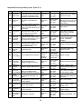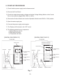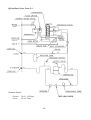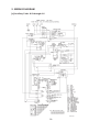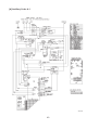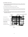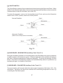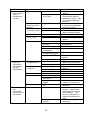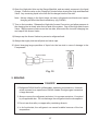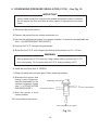
1
NO.
E2DA-581
ISSUED: OCT. 15, 2001
REVISED: JUL. 27, 2004
HOSHIZAKI
MODULAR FLAKER
MODEL
FM-1000ASFE3
FM-1000ASFE3-N
SERVICE MANUAL
CONTENTS
PAGE
I. SPECIFICATIONS ------------------------------------------------------------------------------------1. DIMENSIONS/CONNECTIONS --------------------------------------------------------------[a] FM-1000ASFE3, FM-1000ASFE3-N---------------------------------------------------[b] WITH STORAGE BIN -----------------------------------------------------------------------[c] CONDENSER UNIT MODEL URC-20FE ----------------------------------------------2. SPECIFICATIONS ------------------------------------------------------------------------------[a] FM-1000ASFE3 -----------------------------------------------------------------------------[b] FM-1000ASFE3-N --------------------------------------------------------------------------[c] URC-20FE -------------------------------------------------------------------------------------
1
1
1
2
3
4
4
5
6
II. GENERAL INFORMATION -------------------------------------------------------------------------- 7
1. CONSTRUCTION --------------------------------------------------------------------------------- 7
2. CONTROLLER BOARD ----------------------------------------------------------------------- 10
[a] OPERATION PANEL ----------------------------------------------------------------------- 10
[b] DETAILS OF FUNCTIONS ---------------------------------------------------------------- 11
[c] MAIN BOARD LAYOUT (Auxiliary Code: Before C-1) ------------------------------ 13
[d] MAIN BOARD LAYOUT (Auxiliary Code: From C-1) -------------------------------- 14
[e] SUB BOARD - GEAR MOTOR LAYOUT (Auxiliary Code: From C-1) ----------- 15
[f] SUB BOARD - FAN MOTOR LAYOUT (Auxiliary Code: From C-1) ------------- 16
[g] SETTING AND CHECKING OPERATION --------------------------------------------- 17
III. INSTALLATION AND OPERATING INSTRUCTIONS ---------------------------------------- 25
1. LOCATION ---------------------------------------------------------------------------------------- 25
2. ELECTRICAL CONNECTIONS -------------------------------------------------------------- 25
3. INSTALLATION OF REMOTE CONDENSER UNIT ------------------------------------- 26
[a] LOCATION ------------------------------------------------------------------------------------ 26
[b] INSTALLATION ------------------------------------------------------------------------------ 26
[c] ELECTRICAL CONNECTION ------------------------------------------------------------ 28
4. WATER SUPPLY AND DRAIN CONNECTIONS ----------------------------------------- 29
5. START-UP PROCEDURE -------------------------------------------------------------------- 30
IV. MAINTENANCE AND CLEANING INSTRUCTIONS ---------------------------------------- 32
1. EXTRUDING HEAD, HOUSING BEARING, AUGER BEARING ---------------------- 32
2. MECHANICAL SEAL --------------------------------------------------------------------------- 32
3. GEAR MOTOR ----------------------------------------------------------------------------------- 33
4. CONDENSER ------------------------------------------------------------------------------------ 33
5. WATER VALVE --------------------------------------------------------------------------------- 33
6. CLEANING OF WATER SYSTEM ----------------------------------------------------------- 34
7. PERIODICAL CLEANING --------------------------------------------------------------------- 36
V. TECHNICAL INFORMATION --------------------------------------------------------------------- 37
1. WATER CIRCUIT AND REFRIGERANT CIRCUIT --------------------------------------- 37
2. WIRING DIAGRAM ------------------------------------------------------------------------------ 39
3. TIMING CHART AND SEQUENCE OF OPERATION ----------------------------------- 42
[a] STARTUP, ICEMAKING OPERATION ------------------------------------------------- 42
i
[b] STOP BUTTON ------------------------------------------------------------------------------ 42
[c] AUTOMATIC FLUSH CYCLE ------------------------------------------------------------ 43
[d] BIN CONTROL SWITCH (Storage Bin full for less than 60 minutes) ------------- 44
[e] BIN CONTROL SWITCH (Storage Bin full for more than 60 minutes)------------ 45
[f] BIN CONTROL SWITCH (Checking Actuator) ---------------------------------------- 46
[g] CHUTE SWITCH ---------------------------------------------------------------------------- 47
[h] SUB BOARD - GEAR MOTOR ----------------------------------------------------------- 47
[i] SUB BOARD - FAN MOTOR ------------------------------------------------------------- 47
4. PERFORMANCE DATA ----------------------------------------------------------------------- 48
[a] FM-1000ASFE3 ----------------------------------------------------------------------------- 48
[b] FM-1000ASFE3-N -------------------------------------------------------------------------- 49
VI. ADJUSTMENT OF COMPONENTS ----------------------------------------------------------- 50
1. ADJUSTMENT OF FLAKE SIZE ------------------------------------------------------------ 50
VII. SERVICE DIAGNOSIS ---------------------------------------------------------------------------- 51
1. NO ICE PRODUCTION ------------------------------------------------------------------------- 51
2. LOW ICE PRODUCTION ---------------------------------------------------------------------- 53
3. OTHERS ------------------------------------------------------------------------------------------- 53
VIII. REMOVAL AND REPLACEMENT OF COMPONENTS --------------------------------- 55
1. SERVICE FOR REFRIGERANT LINES ---------------------------------------------------- 55
[a] SERVICE INFORMATION ----------------------------------------------------------------- 55
[b] REFRIGERANT RECOVERY ------------------------------------------------------------ 56
[c] EVACUATION AND RECHARGE ------------------------------------------------------- 56
2. BRAZING ------------------------------------------------------------------------------------------ 57
3. COMPRESSOR --------------------------------------------------------------------------------- 58
4. DRIER ---------------------------------------------------------------------------------------------- 59
5. EXPANSION VALVE --------------------------------------------------------------------------- 60
6. CONDENSING PRESSURE REGULATOR (C.P.R.) ----------------------------------- 61
7. EVAPORATOR ASSEMBLY ----------------------------------------------------------------- 62
8. CONTROL WATER VALVE ------------------------------------------------------------------ 66
9. FLUSH WATER VALVE ----------------------------------------------------------------------- 67
10. CONTROLLER BOARD ----------------------------------------------------------------------- 68
[a] MODIFICATION ------------------------------------------------------------------------------ 68
[b] REPLACEMENT ---------------------------------------------------------------------------- 68
ii
I. SPECIFICATIONS
1. DIMENSIONS/CONNECTIONS
[a] FM-1000ASFE3, FM-1000ASFE3-N
OPERATION WINDOW
(From Auxiliary Code "C-1")
Bottom View
1
[b] WITH STORAGE BIN
2
[c] CONDENSER UNIT MODEL URC-20FE
3
2. SPECIFICATIONS
[a] FM-1000ASFE3
AC SUPPLY VOLTAGE
AMPERAGE
STARTING AMPERAGE
ELECTRIC CONSUMPTION
POWER FACTOR
POWER SUPPLY CAPACITY
ICE PRODUCTION PER 24h
1 PHASE 230V / 3 PHASE 400V
50Hz
Approx. 7.1A
(Ambient temp. 32°C, Water temp. 21°C)
Approx. 35A
Approx. 3.21kW
(Ambient temp. 32°C, Water temp. 21°C)
65%
Min 6.1kVA (8.8A)
Approx. 1020 kg (Ambient temp. 10°C, Water temp. 10°C)
Approx. 950 kg (Ambient temp. 21°C, Water temp. 15°C)
Approx. 880 kg (Ambient temp. 32°C, Water temp. 21°C)
WATER CONSUMPTION PER 24h Approx. 1.03 m3 (Ambient temp. 10°C, Water temp. 10°C)
Approx. 0.96 m3 (Ambient temp. 21°C, Water temp. 15°C)
Approx. 0.89 m3 (Ambient temp. 32°C, Water temp. 21°C)
SHAPE OF ICE
Flake
MAX.STORAGE CAPACITY
Not Applicable
DIMENSIONS (DRAWING No.)
765(W) x 698(D) x 898(H) (343321)
EXTERIOR
Stainless Steel, Galvanized Steel (Rear)
INSULATION
Polyurethane Foam
CONNECTION - ELECTRIC
Permanently connected
- WATER SUPPLY
Inlet
G 3/4”
(Connected at rear side)
- DRAIN
Outlet R 3/4” x 2 (Connected at rear side)
- REFRIGERATION
Discharge Line 1-1/16-12 UNF Fitting (Connected at rear side)
CIRCUIT
Liquid Line
5/8-18 UNF Fitting
(Connected at rear side)
ICE MAKING SYSTEM
Auger type
HARVESTING SYSTEM
Direct driven Auger (400W Gear Motor)
COMPRESSOR
Hermetic Compressor Model CS33K3E-TFD
CONDENSER
Air-cooled Remote Condenser Unit URC-20FE Recommended
EVAPORATOR
Copper Tube on Cylinder
REFRIGERANT CONTROL
Thermostatic Expansion Valve
REFRIGERANT CHARGE
R404A 6800g (within URC-20FE 3500g)
BIN CONTROL SYSTEM
Mechanical Bin Control (Time Delay Controlled)
ICE MAKING WATER CONTROL
Float Switch and Water Valve
ELECTRICAL PROTECTION
Class I Appliance
Manual-reset Circuit Breaker (10A)
COMPRESSOR PROTECTION
Auto-reset Overload Protector, Auto-reset Pressure Switch
GEAR MOTOR PROTECTION
Manual-reset Circuit Breaker (6A), Auto-reset Thermal Protector
LOW WATER PROTECTION
Float Switch and Timer
BIN CONTROL PROTECTION
Mechanical Switch
WEIGHT
Net weight 153 kg / Gross weight 168 kg
PACKAGE
Carton 911mm(W) x 844mm(D) x 1030mm(H)
ACCESSORIES
Scoop, Mounting Bracket, Installation Kit (Water Supply, Drain)
OPTIONAL EQUIPMENT
Pre-charged Tubing Kits: R404-55610
(ø15.88 x 16.7m, ø9.52 x 16.7m)
OPERATION CONDITIONS
AMBIENT TEMP.
5-40°C
WATER SUPPLY TEMP.
5-35°C
WATER SUPPLY PRESSURE 0.5-8 bar (0.05-0.8MPa)
We reserve the right to make changes in specifications and design without prior notice.
4
[b] FM-1000ASFE3-N
AC SUPPLY VOLTAGE
AMPERAGE
STARTING AMPERAGE
ELECTRIC CONSUMPTION
POWER FACTOR
POWER SUPPLY CAPACITY
ICE PRODUCTION PER 24h
1 PHASE 230V / 3 PHASE 400V
50Hz
Approx. 7.1A
(Ambient temp. 32°C, Water temp. 21°C)
Approx. 35A
Approx. 3.21kW
(Ambient temp. 32°C, Water temp. 21°C)
65%
Min 6.1kVA (8.8A)
Approx. 850 kg (Ambient temp. 10°C, Water temp. 10°C)
Approx. 800 kg (Ambient temp. 21°C, Water temp. 15°C)
Approx. 740 kg (Ambient temp. 32°C, Water temp. 21°C)
WATER CONSUMPTION PER 24h Approx. 0.86 m3 (Ambient temp. 10°C, Water temp. 10°C)
Approx. 0.81 m3 (Ambient temp. 21°C, Water temp. 15°C)
Approx. 0.75 m3 (Ambient temp. 32°C, Water temp. 21°C)
SHAPE OF ICE
Nugget
MAX.STORAGE CAPACITY
Not Applicable
DIMENSIONS (DRAWING No.)
765(W) x 698(D) x 898(H) (343321)
EXTERIOR
Stainless Steel, Galvanized Steel (Rear)
INSULATION
Polyurethane Foam
CONNECTION - ELECTRIC
Permanently connected
- WATER SUPPLY
Inlet
G 3/4”
(Connected at rear side)
- DRAIN
Outlet R 3/4” x 2 (Connected at rear side)
- REFRIGERATION
Discharge Line 1-1/16-12 UNF Fitting (Connected at rear side)
CIRCUIT
Liquid Line
5/8-18 UNF Fitting
(Connected at rear side)
ICE MAKING SYSTEM
Auger type
HARVESTING SYSTEM
Direct driven Auger (400W Gear Motor)
COMPRESSOR
Hermetic Compressor Model CS33K3E-TFD
CONDENSER
Air-cooled Remote Condenser Unit URC-20FE Recommended
EVAPORATOR
Copper Tube on Cylinder
REFRIGERANT CONTROL
Thermostatic Expansion Valve
REFRIGERANT CHARGE
R404A 6800g (within URC-20FE 3500g)
BIN CONTROL SYSTEM
Mechanical Bin Control (Time Delay Controlled)
ICE MAKING WATER CONTROL
Float Switch and Water Valve
ELECTRICAL PROTECTION
Class I Appliance
Manual-reset Circuit Breaker (10A)
COMPRESSOR PROTECTION
Auto-reset Overload Protector, Auto-reset Pressure Switch
GEAR MOTOR PROTECTION
Manual-reset Circuit Breaker (6A), Auto-reset Thermal Protector
LOW WATER PROTECTION
Float Switch and Timer
BIN CONTROL PROTECTION
Mechanical Switch
WEIGHT
Net weight 153 kg / Gross weight 168 kg
PACKAGE
Carton 911mm(W) x 844mm(D) x 1030mm(H)
ACCESSORIES
Scoop, Mounting Bracket, Installation Kit (Water Supply, Drain)
OPTIONAL EQUIPMENT
Pre-charged Tubing Kits: R404-55610
(ø15.88 x 16.7m, ø9.52 x 16.7m)
OPERATION CONDITIONS
AMBIENT TEMP.
5-40°C
WATER SUPPLY TEMP.
5-35°C
WATER SUPPLY PRESSURE 0.5-8 bar (0.05-0.8MPa)
We reserve the right to make changes in specifications and design without prior notice.
5
[c] URC-20FE
AC SUPPLY VOLTAGE
115/50/1 (Connection to Icemaker)
FAN MOTOR
115V
EXTERIOR DIMENSIONS (WxDxH)
46-3/8” x 15-11/16” x 25-15/16” (1178 x 398 x 659 mm)
Total 2.6FLA
130W
DIMENSIONS INCLUDING LEGS (WxDxH) 48-7/16” x 18-1/8” x 40-7/8” (1230 x 460 x 1039 mm)
EXTERIOR FINISH
Galvanized Steel
WEIGHT
Net 104 lbs. (47 kg)
CONNECTIONS - ELECTRIC
Permanent Connection
- REFRIGERANT
Shipping 115 lbs. (52 kg)
Discharge Line 1-1/16”-12 UNF Fitting (#10 AEROQUIP)
Liquid Line
5/8”-18 UNF Fitting
CONDENSER
Air-cooled, Fin and Tube Type
FAN MOTOR PROTECTION
Thermal Protection
REFRIGERANT CONTROL
Condensing Pressure Regulator
(#6 AEROQUIP)
Setting 14.4 bar (Saturation Temp. 33°C)
REFRIGERANT CHARGE
R404A 7 lbs. 11 oz. (3500 g)
DESIGN PRESSURE
High 467 PSIG (32.2 bar)
OPERATING CONDITIONS
VOLTAGE RANGE
104 - 127V
AMBIENT TEMP.
-20 - 122°F (-29 - 50°C)
ACCESSORIES - SUPPLIED
DRAWING NO. (DIMENSIONS)
Leg
2 pcs
Hex. Head Bolt w / Washer
8 x 16
8 pcs
Hex. Nut
8
8 pcs
438201
* We reserve the right to make changes in specifications and design without prior notice.
6
II. GENERAL INFORMATION
1. CONSTRUCTION
Modular flaker model FM-1000ASFE3(-N) includes Water Supply, Evaporator, Compressor,
Condenser and Control Assemblies. As the unit is not equipped with an Ice Storage Bin, this
must be purchased separately as an optional extra.
Door
Ice Storage Bin
Condenser
Leg
Fan Motor Lead
Power Cord
Ice Chute
Bin Control Switch
Spout
Control Box
Reservoir
Compressor
Evaporator
Gear Motor
7
Control Box
Evaporator
Gear Motor
Drier
Water Valve
Reservoir
Ice Chute
Receiver
Compressor
8
ICE MAKING UNIT
Hex Bolt
Cutter
Extruding Head
Belt Heater
Socket Head Cap Screw
w/ Plastic Seal
Casing
Auger
Mechanical Seal
Gear Motor
Socket Head
Cap Screw
Housing
Coupling
9
2. CONTROLLER BOARD
The electric circuit has been changed from a Timer Board to a Controller Board. The
Controller Board consists of the Operation Board (Controller Board - Operation) and the
Main Board (Controller Board - Main). From the auxiliary code “C-1”, the Sub Board - Gear
Motor and Sub Board - Fan Motor (Fan Speed Control Board) are also provided. The Main
Board is common for all the auger type icemakers except for the Dip Switch settings.
The Operation Board is equipped with the Display (7 segments, 2 digits) and the three
Operation Buttons “ICE”, “STOP” and “OPTION” which are for checking the operating
conditions during servicing and user operation.
The Main Board is equipped with Relays for the Compressor, Gear Motor, Control Water
Valve and Flush Water Valve.
The Sub Board - Gear Motor senses the current through the Gear Motor. When the current
rises, the Sub Board will bypass the discharge gas to the Suction Pipe to reduce the load on
the Gear Motor.
The Sub Board - Fan Motor senses the condensing temperature to keep it within the proper
range.
[a] OPERATION PANEL
Positioned on the right side of the Control Box Cover is the Voltage
Setting Switch (220/230/240V), Operation Switch (Run/Stop), Motor
Protector (10A) and Gear Motor Protector (6A), and on the left side is
the Display with the Ice, Stop and Option Buttons.
10
[b] DETAILS OF FUNCTIONS
Operation Mode Display Indications
Item
Display Indication
Details
Icemaking
ICE
DRAIN
STOP
Illuminates:
1) During icemaking cycle, or
2) When Storage Bin is full
Automatic Drain
ICE
DRAIN
STOP
Illuminates:
1) For 15 minutes during automatic drain cycle after 6 hours
in continuous icemaking cycle from the last drain cycle, or,
after 1 hour with Storage Bin full, or
2) When Ice Button is pushed with Stop Lamp blinking
Manual Stop
ICE
DRAIN
STOP
Illuminates when Stop Button is pushed Æ Blinks for 15
minutes (drain control) Æ Illuminates constantly (end of drain
control) Æ Turn OFF the power supply (See instruction label)
Interlock Error
(“E__” indication)
ICE
DRAIN
STOP
Blinks in case of interlock error Æ Indicates “E__” Æ Possible
cause can be located by the error code table.
Non-Interlock Error
No indication for non-interlock errors. Check error records for
non-interlock stoppages (“c__” indication).
Button Operations
Operator
User
Service
Personnel
Factory
Indication, Function
Start icemaking
Stop icemaking after drain
Indicate total compressor operating
hours
Indicate cycle time
Indicate error records
Indicate ongoing non-interlock error
Delete error records
Service mode
Delete total compressor operating
hours + Production line inspection
mode
Button Operation
Ice Button
Stop Button
Option Button
Option Button + Ice Button
Option Button + Stop Button
Option Button + Stop Button + Stop Button after “—”
indication
Operation Switch + Stop Button + Option Button
Operation Switch + Option Button
Operation Switch + Ice Button + Stop Button + Option
Button
Note: In case of interlock error (“E__” indication), the icemaker will not respond to the
user’s button operation.
If the icemaker has stopped because of a non-interlock error, the user’s button
operation can change the indication, but the icemaking or drain cycle cannot start
until the error is cancelled.
11
Basic Control Sequences
Start icemaking:
Water supply Æ Reservoir fills Æ Gear Motor ON Æ Compressor ON after 5 minutes
Stop drain:
Compressor OFF Æ Gear Motor OFF after 5 minutes Æ Water supply Æ Reservoir fills
Æ Flush Water Valve ON Æ Flush Water Valve OFF after 10 minutes
Bin full (self-contained type):
Bin Control Switch continuously OFF for 7 seconds Æ Compressor OFF Æ Gear Motor
OFF after 5 minutes Æ Bin Control Switch continuously ON for 7 seconds Æ Icemaking
starts
Bin full (modular type):
Bin Control Switch continuously OFF for 7 seconds Æ Compressor and Gear Motor
OFF Æ Bin Control Switch continuously ON for 7 seconds Æ Icemaking starts
Automatic drain:
After 6 hours from the last drain cycle or after 1 hour with Storage Bin full
Service mode:
Shortens the 5 minute delay before the initial icemaking cycle for ease of service
(Water supply Æ Reservoir fills Æ Gear Motor ON Æ Compressor ON after 30
seconds)
Production line inspection mode:
Switches to the following controls for 30 minutes to shorten the finished product
inspection and resets automatically after 30 minutes.
Compressor start delay at the beginning of icemaking cycle: 5 minutes Æ 10
seconds
Gear Motor stop delay at the end of icemaking cycle: 5 minutes Æ 10 seconds
No error records, Dip Switch setting indication at startup
Intermittent operation of Control Water Valve in case of low water: 5 minutes
OFF, 5 minutes ON Æ 10 seconds OFF, 5 minutes ON
12
[c] MAIN BOARD LAYOUT (Auxiliary Code: Before C-1)
K5 FLOAT SWITCH
K8 ROTATION SENSOR
K7 BIN CONTROL SWITCH
DIP SWITCH
K7 PRESSURE SWITCH
K1 24V AC INPUT
K2 CONTROL WATER VALVE
K2 FLUSH WATER VALVE
K3 FAN MOTOR FOR CONTROL BOX
12V DC OUTPUT
K6 OPERATION BOARD
LOT NO. STAMP
K4 GEAR MOTOR SENSOR
13
[d] MAIN BOARD LAYOUT (Auxiliary Code: From C-1)
K14 GEAR MOTOR
K4
K10
K13
DIP SWITCH
K5 FLOAT SWITCH
K8
K12
K9
K3 NOT USED
K2 WATER VALVE
K7 BIN CONTROL &
PRESSURE SWITCH
K6
K11
K1 POWER SUPPLY
14
[e] SUB BOARD - GEAR MOTOR LAYOUT (Auxiliary Code: From C-1)
K4 GEAR MOTOR
K7 HOT GAS VALVE
K2 POWER SUPPLY
K3 HEATER
K1 CONTROLLER
DIP SWITCH
BOARD - MAIN
K6 NOT USED
K5 RESISTOR &
ROTATION SENSOR
15
[f] SUB BOARD - FAN MOTOR LAYOUT (Auxiliary Code: From C-1)
K1 JUMPER
K2 FAN MOTOR
K5 NOT USED
DIP SWITCH
K3 THERMISTOR &
K4 THERMISTOR
RESISTOR
16
[g] SETTING AND CHECKING OPERATION
The Controller Board has the following functions for setting and checking:
(1) Shorten startup time
(2) Indicate total operating hours
(3) Indicate error record
(4) Delete error record
(5) Indicate cycle time
(6) Apply to any model by adjusting Dip Switch
(1) Shorten startup time
Starting from the FM-481 model change, the startup control has been changed to “Power
ON Æ Float Tank fills up Æ Gear Motor starts Æ Compressor starts after 5 min (formerly 1
min)”.
For the initial startup after the power supply is turned on, the Compressor start delay of “5
min” can be shortened to “30 sec” by the following button operation.
(This is useful to shorten maintenance and service operation, but could be a cause of trouble
if the icemaker is started up with ice still remaining inside the Evaporator Casing.)
Button Operation: (Power supply ON, Operation Switch on “STOP”)
1) While pressing the Option Button, move the Operation Switch to the “RUN” position.
2) Release the Option Button when the Display shows the total compressor operating hours
(_ _ thousand hours).
3) The Display illuminates “ICE”, and the icemaker starts up in the shortened startup mode.
(2) Indicate total operating hours
The total operating hours are indicated in two digits (_ _ thousand hours) by the following
button operation. The total operating hours indicated may be shorter than actual time and
should be used to determine the required maintenance and part replacement. The hours
indicated cannot be reset.
Button Operation: (Power supply ON, Operation Switch on “RUN”)
1) Only while the Option Button is pressed, the Display changes from the normal indication
to the total operating hours.
2) When the Option Button is released, the Display changes from the total operating hours
back to the normal indication.
(ex.)
“00” is indicated for total operating hours of 0 to 999 hours.
“01” is indicated for total operating hours of 1,000 to 1,999 hours.
“98” is indicated for total operating hours of 98,000 to 98,999 hours.
17
“99” is indicated for total operating hours of 99,000 hours and more.
(The indication of total operating hours is up to “99”.)
If the Display shows “- -” while the Option Button is pressed, the Controller Board must have
a problem (The icemaker can continue normal icemaking operation but cannot memorize
the total operating hours and error record).
(3) Indicate error record
Use this function to get detailed information on the icemaker’s condition when maintaining or
servicing the icemaker.
The error record is indicated by the following button operation and remains even if the power
is turned off.
The indicated error record may include “c1” to “c4” errors as well as “E0” to “EF” errors when
problems or stoppages have occurred. Those errors are recorded for low water (c1),
abnormal head pressure (c2) and drain error (c4).
For example, if the indicated error record includes “c2” during inspection, check the
Condenser and vicinity to locate the cause of abnormal head pressure.
Button Operation: (Power supply ON, Operation Switch on “RUN”)
1) Keep on pressing the Option Button until step 4).
2) The Display changes from the normal indication to the total operating hours.
3) (While pressing the Option Button) Press the Stop Button once.
4) The Display indicates the error record.
5) Release the Option Button. The Display changes back to the normal indication.
(ex.)
The Display indicates the record of the last eight errors from the latest to the oldest for 1 sec
each.
If there is no error record, the Display indicates “- -“.
If there is a record of three errors “E0” (latest), “E1” and “E2” (oldest), the Display indicates
“E0” (1 sec) Æ “E1” (1 sec) Æ “E2” (1 sec) Æ “- -“. The “- -“ indication means there is no
more error record.
The icemaker may stop icemaking operation even when the Display is illuminating “ICE”. In
this case, the Bin Control Switch may have operated, or the icemaker may be in the error
“c1” or “c2”. To identify the cause during maintenance or service, check the ongoing error by
the following button operation. If no error record is indicated, the cause of the above
suspension is determined to be the Bin Control Switch operation.
Button Operation:
1) Keep on pressing the Option Button until step 7).
2) The Display changes from the normal indication to the total operating hours.
3) (While pressing the Option Button) Press the Stop Button once.
4) The Display indicates the error record.
18
5) Check that the error record indication becomes “- -“.
6) (While pressing the Option Button) Press the Stop Button once again.
7) The Display indicates the error record (ongoing error).
8) Release the Option Button. The Display changes back to the normal indication.
(ex.)
If there is no ongoing error, the Display indicates “- -“.
If the icemaker is in the errors “E0”, “c1” and “c2”, the Display repeatedly indicates “E0” (1
sec) Æ “c1” (1 sec) Æ “c2” (1 sec).
(4) Delete error record
The error record is not deleted by turning off the power supply but is deleted by the following
button operation. To make the next service diagnosis easier, it is recommended to delete
the error record during maintenance or service.
Button Operation: (Power supply ON, Operation Switch on “STOP”)
1) While pressing both the Option Button and Stop Button together, move the Operation
Switch to the “RUN” position.
2) When the Display illuminates “ICE”, release the Stop Button first and then the Option
Button.
(5) Indicate cycle time
The cycle time to estimate the current ice production capacity is indicated by the following
button operation.
This cycle time means the time since the Float Tank fills up during Compressor operation
until the next icemaking water supply starts. The last five cycles are recorded.
This record is deleted when the power supply is turned off.
Button Operation: (Power supply ON, Operation Switch on “RUN”)
1) Keep on pressing the Option Button until step 4).
2) The Display changes from the normal indication to the total operating hours.
3) (While pressing the Option Button) Press the Ice Button once.
4) The Display indicates the cycle time.
5) Release the Option Button. The Display changes back to the normal indication.
As the Display can indicate only two digits, a complex system is used to indicate the cycle
time record. The max five cycles are indicated from the latest to the oldest as “_ _” min “_ _”
sec …… “_ _” min “_ _” sec. The Display illuminates “ICE” after all the record has been
indicated.
To distinguish “min” from “sec”, the first digit for “min” is replaced by a letter of the alphabet
as shown below.
19
Actual Digit
0
1
2
3
Letter
o
A
b
c
For example, “A1” “10” stands for 11 min 10 sec.
4
d
5
E
(ex.)
If there is no cycle time record, the Display indicates “- -“.
If the cycle time record is 10 min 30 sec (latest), 9 min 45 sec and 25 min 10 sec (oldest), the
Display indicates “A0” (2 sec) Æ “30” (2 sec) Æ “o9” (2 sec) Æ “45” (2 sec) Æ “b5” (2 sec) Æ
“10” (2 sec) Æ “- -“.
The cycle time is related to the ice production capacity as shown in the table below. The less
the ice production capacity is, the longer the cycle time will become.
The ice production capacity depends on ambient and water temperatures. See “V. 4.
PERFORMANCE DATA.”
Cycle Time (reference)
Ice Production
Capacity (kg/d)
100
200
300
400
500
600
700
800
900
1000
1100
1200
1600
2000
2200
Formula
(reference)
CM-230 series
FM-250 series
FM-481 series
9 min 10 sec
4 min 35 sec
3 min 03 sec
2 min 18 sec
1 min 50 sec
1 min 32 sec
1 min 19 sec
Ice
Production =
(kg)
55000
(constant)
Cycle Time
(sec)
FM-1000 series
2 min 57 sec
2 min 21 sec
1 min 58 sec
1 min 41 sec
1 min 28 sec
1 min 19 sec
1 min 11 sec
1 min 04 sec
0 min 59 sec
Ice
Production =
(kg)
70800
(constant)
Cycle Time
(sec)
FM-2000 series
1 min 58 sec
1 min 28 sec
1 min 11 sec
1 min 04 sec
141600
Ice
(constant)
Production =
Cycle Time
(kg)
(sec)
(6) Apply to any model by adjusting Dip Switch
The Controller Board applies to any auger type model by adjusting the Dip Switch.
20
Interlock Errors (Auxiliary Code: Before C-1)
Code
E0
Error
Icemaking
Water Leak
Condition
Following initial water supply,
Float Switch trips at lower float
level after Gear Motor starts but
before Compressor starts.
Operation
Reset
Check/Repair
Whole unit
stops.
Power supply,
Turn OFF Turn ON
Water leaks, Flush
Water Valve not closing
Gas leaks, Control
Water Valve not
closing, Air lock in
Evaporator, Freeze up,
Float Switch
E1
Icemaking
Error
Icemaking cycle takes too long.
Whole unit
stops.
Power supply,
Turn OFF Turn ON
E2
Float Switch
Error
With Flush Water Valve OFF,
Float Switch trips at both upper
and lower float levels for 2
seconds.
Whole unit
stops.
Power supply,
Turn OFF Turn ON
Float Switch
E4
Abnormal
High Side
Pressure
Pressure Switch trips 5 times
(OFF for 5 seconds) in 1 hour of
Compressor operation.
Whole unit
stops.
Power supply,
Turn OFF Turn ON
Fan Motor, Cooling
water circuit,
Refrigeration circuit,
Condenser clogged
E7
Failure
Precaution
N/A
Damage to Evaporator
assembly (See Note 2)
Power supply,
Turn OFF Turn ON
Supply voltage, Gear
Motor locked, hunting or
reversing (See Note 1)
Power supply,
Turn OFF Turn ON
Replace Controller
Board.
E8
Eb
EH
Abnormal
Gear Motor
Amperage
Controller
Board A/D
Conversion
Error
Gear Motor
Rotation
Error
EL
Bin Control
Switch Error
EF
Abnormal
Low Voltage
(FM-481 only)
Gear Motor Amperage Sensor
E7 blinks.
has operated more than 10
times.
(FM-481 only)
Whole unit
Gear Motor Amperage Sensor is
stops.
ON.
Microcomputer fails in
analog-to-digital conversion.
Whole unit
stops.
(Only when Dip Switch 4 is OFF) Whole unit
Rotation Sensor detects error.
stops.
Chute Protection Switch has
operated due to failure of Bin
Control Switch.
(Only when Dip Switch 5 is ON)
Low Voltage Sensor operates 3
times in 24 hours.
Whole unit
stops.
Whole unit
stops.
Whole unit
stops.
None Electric Leak Electric leak or overcurrent.
Power supply,
Turn OFF Turn ON
Power supply,
Turn OFF Turn ON
Power supply,
Turn OFF Turn ON
Power supply,
Turn OFF Turn ON
Supply voltage, Gear
Motor locked, hunting or
reversing
Bin Control Switch
(Only when Dip Switch
5 is ON) Supply voltage
Electric leaks, Fuse,
Overcurrent
Note: 1. The error "E8" is caused by an overload on the Gear Motor which increases the motor
amperage to activate the Amperage Sensor. When "E8" is displayed, the fundamental
cause of the overcurrent must be removed to avoid a repeat of the error. The Gear Motor
amperage will increase if it locks or hunts due to an ice blockage or insufficient torque
caused by low voltage.
2. The error code “E7” blinks after “E8” is displayed ten times. If “E8” appears repeatedly, the
Evaporator assembly must be under excessive load each time (see Note 1 for details).
Repetitive overload on the Evaporator assembly accumulates metal fatigue inside, which
may suddenly break the Auger or twist the Evaporator without any visible symptom. When
“E7” blinks, replace the entire Evaporator assembly including the Evaporator, Auger,
Coupling and Housing. After replacement, reset the Display as follows:
1) Move the Operation Switch to the “STOP” position.
21
2) Turn ON the Dip Switch 4 on the Sub Board.
3) Move the Operation Switch to the “RUN” position.
4) Turn OFF the Dip Switch 4 on the Sub Board.
5) Turn ON the Dip Switch 4 on the Sub Board.
6) Move the Operation Switch to the “STOP” position.
7) Turn OFF the Dip Switch 4 on the Sub Board.
8) While pushing the Option Button and Stop Button on the Operation Panel, move the
Operation Switch to the “RUN” position.
Non-Interlock Errors (Auxiliary Code: Before C-1)
Code
Error
CM Microcomputer
Time Read/Write
“— —” Error
c1
c2
Low Water
Abnormal High
Side Pressure
c3
Abnormal Low
Voltage
c4
Drain Error
Condition
Operation
Reset
Check/Repair
Error records and
compressor operating
hours not available on
display
Microcomputer fails to
read/write properly.
Memory circuit
not available.
Replace
Controller
Board.
Water supply continues
for more than 90
seconds, or Float
Switch trips at lower
float level and does not
reset for more than 60
seconds after water
supply.
Whole unit
stops until
Reservoir fills
up. Only
Control Water
Valve operates
intermittently
every 5
minutes.
Automatically
resets after
Reservoir fills
up.
Water supply
interruption, Control
Water Valve not
opening, Flush Water
Valve not closing, Float
Switch, Water leaks
Whole unit
stops.
Automatically
resets after
Pressure
Switch turns
ON.
Fan Motor, Cooling
water circuit,
Refrigeration circuit,
Condenser clogged
Whole unit
stops.
Automatically
resets after
voltage stays
above 69 94% rating for
120 seconds.
Supply voltage
Pressure Switch stays
OFF for 5 seconds.
(Only when Dip Switch
5 is ON)
Voltage stays below 64
- 84% rating for more
than 1 second with
Compressor ON and
Control Water Valve
OFF.
Float Switch trips at
upper float level in 10
minutes after Flush
Water Valve turns ON.
Indication only. N/A
22
Flush Water Valve not
opening, Control Water
Valve not closing
Interlock Errors (Auxiliary Code: From C-1)
Code
Error
E0
Icemaking
Water Leak
E1
Icemaking
Error
E2
Float Switch
Error
E3
Gear Motor
Error
E4
Abnormal
High Side
Pressure
Reset
Check/Repair
Power supply,
Turn OFF Turn ON
Water leaks, Flush Water
Valve not closing
Whole unit
stops.
Power supply,
Turn OFF Turn ON
Gas leaks, Control Water
Valve not closing, Air lock
in Evaporator, Freeze up,
Float Switch
Whole unit
stops.
Power supply,
Turn OFF Turn ON
Float Switch
Whole unit
stops.
Power supply,
Turn OFF Turn ON
Gear Motor protective
circuit (TPO, Overload,
etc.) operated.
Pressure Switch trips 5 times
(OFF for 5 seconds) in 1 hour
of Compressor operation.
Whole unit
stops.
Power supply,
Turn OFF Turn ON
Fan Motor, Cooling water
circuit, Refrigeration
circuit, Condenser
clogged
E5
Gear Motor
Relay fused
(Only when Dip Switch 4 is
ON) Gear Motor Relay is OFF
with Gear Motor protective
circuit detector ON.
Whole unit
(except GM)
stops.
Power supply,
Turn OFF Turn ON
Replace Controller Board.
E6
Phase
Reversal
Error
Phase Reversal
Whole unit
stops.
Power supply,
Turn OFF Turn ON
(3 phase models only)
Phase reversal
Abnormal
Low Voltage
Whole unit
stops until
Low Voltage Sensor operates. normal
voltage is
resumed.
Automatically
resets when
normal voltage
is resumed.
Supply voltage
Microcomputer fails in
analog-to-digital conversion.
Whole unit
stops.
Power supply,
Turn OFF Turn ON
Replace Controller Board.
Rotation Sensor detects error.
Whole unit
stops.
EA
Eb
EE
Controller
Board A/D
Conversion
Error
Gear Motor
Rotation
Error
EF
Abnormal
Low Voltage
EJ
Failure
Precaution
EL
Bin Control
Switch Error
En
EP
EU
Open Circuit
(Sub Board GM)
Setting Error
(Sub Board GM)
Controller
Board Error
(Sub Board GM)
Condition
Operation
Following initial water supply,
Float Switch trips at lower float Whole unit
level after Gear Motor starts
stops.
but before Compressor starts.
Icemaking cycle takes too
long.
With Flush Water Valve OFF,
Float Switch trips at both
upper and lower float levels for
2 seconds.
(Only when Dip Switch 4 is
ON) Gear Motor Relay is ON
with Gear Motor protective
circuit detector OFF.
(Only when Dip Switch 5 is
ON) Low Voltage Sensor
operates 3 times in 24 hours.
Gear Motor Rotation Sensor
has operated more than 10
times.
Chute Protection Switch has
operated due to failure of Bin
Control Switch.
Voltage Sensor circuit on Sub
Board - GM is open.
Whole unit
stops.
Whole unit
stops.
Whole unit
stops.
Whole unit
stops.
Dip Switch on Sub Board - GM Whole unit
is set incorrectly.
stops.
Sub Board - GM fails.
Whole unit
stops.
23
Power supply,
Turn OFF Turn ON
Power supply,
Turn OFF Turn ON
Power supply,
Turn OFF Turn ON
Power supply,
Turn OFF Turn ON
Power supply,
Turn OFF Turn ON
Power supply,
Turn OFF Turn ON
Power supply,
Turn OFF Turn ON
Supply voltage, Gear
Motor locked, hunting or
reversing
(Only when Dip Switch 5
is ON) Supply voltage
Supply voltage, Gear
Motor locked, hunting or
reversing
Bin Control Switch
Continuity of Voltage
Sensor circuit on Sub
Board - GM
Sub Board - GM Dip
Switch setting
Replace Sub Board - GM
Non-Interlock Errors (Auxiliary Code: C-1)
Code
c1
c2
Error
Low Water
Abnormal High
Side Pressure
c3
Abnormal Low
Voltage
c4
Drain Error
Condition
Water supply continues
for more than 90
seconds, or Float
Switch trips at lower
float level and does not
reset for more than 60
seconds after water
supply.
Pressure Switch stays
OFF for 5 seconds.
(Only when Dip Switch
5 is ON)
Voltage stays below 64
- 84% rating for more
than 1 second with
Compressor ON and
Control Water Valve
OFF.
Float Switch trips at
upper float level in 10
minutes after Flush
Water Valve turns ON.
Operation
Whole unit
stops until
Reservoir fills
up. Only
Control Water
Valve operates
intermittently
every 5
minutes.
Reset
Check/Repair
Automatically
resets after
Reservoir fills
up.
Water supply
interruption, Control
Water Valve not
opening, Flush Water
Valve not closing, Float
Switch, Water leaks
Whole unit
stops.
Automatically
resets after
Pressure
Switch turns
ON.
Condenser clogged,
Refrigeration circuit
Whole unit
stops.
Automatically
resets after
voltage stays
above 69 94% rating for
120 seconds.
Supply voltage
Flush Water Valve not
opening, Control Water
Valve not closing
Indication only. N/A
Dip Switch Setting
Controller Board - Main
461914-04
[K-1, K-2, A-0]
461914-06
[A-1, B-1, B-2]
464015-06
[From C-1]
Sub Board - Gear Motor
463949-03
[From C-1]
Sub Board - Fan Motor
464769-01
[From C-1]
Dip Switch
4
5
1
2
3
ON
ON
ON
OFF
ON
OFF
ON
ON
OFF
ON
ON
OFF
ON
ON
OFF
ON
OFF
OFF
1
2
3
4
OFF
OFF
ON
ON
1
2
3
4
ON
OFF
OFF
ON
24
Dip Switch
5
6
OFF
OFF
Dip Switch
5
6
OFF
OFF
6
7
8
ON
OFF
7
8
9
10
OFF
OFF
ON
OFF
7
8
9
10
OFF
OFF
OFF
OFF
III. INSTALLATION INSTRUCTIONS
1. LOCATION
WARNING
1. This icemaker is not intended for outdoor use. Normal operating ambient
temperature should be within 5°C to 40°C. Normal operating water
temperature should be within 5°C to 35°C. Operation of the icemaker, for
extended periods, outside of these normal temperature ranges may affect
production capacity.
2. The icemaker should not be located next to ovens, grills or other high heat
producing equipment.
3. The location should provide a firm and level foundation for the equipment.
4. Allow 15 cm clearance at rear and sides for proper air circulation and ease
of maintenance and/or service should they be required. Allow 60 cm
clearance on top to allow for removal of the Auger.
5. This appliance is not suitable for installation in an area where a water jet
could be used and where dripping is not allowed.
6. Do not place anything on top of the icemaker or in front of the Louver.
2. ELECTRICAL CONNECTIONS
WARNING
THIS APPLIANCE MUST BE EARTHED
This icemaker requires an earth that meets the national and local electrical
code requirements. To prevent possible severe electrical shock to individuals
or extensive damage to equipment, install a proper earth wire to the icemaker.
* This icemaker must have a separate power supply or receptacle of 3N~400V (Three-phase
star, four-wire; earthed neutral).
* When the power supply cord is connected, it must have a capacity of not less than 10A.
* The fixed wiring must incorporate a means for disconnection from the supply having a contact
separation of at least 3 mm in all poles.
* Usually an electrical permit and services of a licensed electrician are required.
25
* If the supply cord is damaged, it must be replaced by the manufacturer or its service agent
of a similarly qualified person in order to avoid a hazard.
* The maximum permissible system impedance (Zmax) at the interface point of the power
supply to be connected with this icemaker must be 0.0225+j0.0225 ohm. Determine in
consultation with the supply authority, if necessary, that the icemaker is connected only to a
supply of 0.0225+j0.0225 ohm or less.
3. INSTALLATION OF REMOTE CONDENSER UNIT
[a] LOCATION
Min. 60 cm clearance
The Condenser is intended for outdoor use and
must be positioned in a permanent site under the
following guidelines:
* A firm and flat site.
Air
Air
* Should not be exposed to harsh or adverse
weather conditions.
* Preferably a dry and well ventilated area with 60
cm clearance on both front and rear for ease of
maintenance and service should they be required.
Locate
Legs
Fig. 1
* Normal condenser ambient temperature: -15°C to +40°C. Temperatures not within this
operating range may affect the production capacity of the icemaker.
* The maximum line length is 20 m.
* The Condenser should not be installed more than 6 m above the height of the icemaker or
more than 2 m below it.
Note: If the recommended guidelines of the installation are exceeded, the icemaker
performance may be reduced.
[b] INSTALLATION
Hexagon Bolts
(with Split Lock
Washer and
Flat Washer)
1) Secure the Legs to the Condenser Unit with eight
M8 x 16 mm Hexagon Bolts and M8 Nuts as
shown in the illustration. See Fig. 2.
Note: Locate the Legs symmetrically.
M8 Hexagon
Nuts
26
Fig. 2
2) The Legs have eight mounting holes to secure the Legs to a firm base using eight bolts
(not supplied).
3) Install enough length of two copper tubings provided with Aeroquip couplings between the
icemaker and the Condenser Unit. The two copper tubings should be insulated separately.
See Fig. 3.
* Precharged tubing kits, available as optional equipment from HOSHIZAKI EUROPE,
are recommended.
6 m:
10.6 m:
16.7 m:
R404-20610
R404-35610
R404-55610
4) Line sets fabricated in the field should be evacuated through the charging ports on the
Aeroquip couplings and charged with R404A refrigerant vapor to a pressure of 1 - 2 bar
(0.1 - 0.2 MPa).
Note: Factory fabricated tubing kits are precharged and do not need to be evacuated.
5) Remove the plastic caps protecting the couplings. Attach the two refrigerant lines to the
male couplings on the icemaker and the Remote Condenser Unit. Each refrigerant line
must be connected as follows:
Icemaker discharge refrigerant line - 5/8" OD tubing to "DIS" of condenser unit
Icemaker liquid refrigerant line - 3/8" OD tubing to "LIQ" of condenser unit
Note: Make the connections at the Remote Condenser first and then at the icemaker.
Icemaker
Power Supply Cord
Terminal Box
(Fan Motor Leads inside)
Female Coupling
Liquid Line
Condenser Unit
Louver Panel
Terminal Box
(Fan Motor Leads inside)
3/8” OD
Discharge Line
Liquid Line
3/8” OD
5/8” OD
Female Coupling
Discharge Line
Pipe Insulation
Fig. 3
27
5/8” OD
[c] ELECTRICAL CONNECTIONS
WARNING
THIS APPLIANCE MUST BE EARTHED
This Remote Condenser Unit requires an earth that meets the national and
local electrical code requirements. To prevent possible severe electrical shock
to individuals or extensive damage to equipment, install a proper earth wire to
the icemaker.
* This Condenser Unit must be connected to the Fan Motor leads in the Terminal Box on the
icemaker.
* Use a lead with conductors of not less than 0.5 mm2 cross section, having a vinyl sheath of
“H05VV” or higher grade.
* Protect the leads with a conduit.
* Usually an electrical permit and services of a licensed electrician are required.
1) Remove the Panel.
2) Remove the Terminal Box Cover.
3) Connect the Fan Motor leads in the Terminal Box of the Remote Condenser Unit to the Fan
Motor leads in the Terminal Box of the HOSHIZAKI remote air-cooled icemaker.
4) Install an earth wire from the icemaker to the Remote Condenser Unit.
5) Replace the Terminal Box Cover and the Panel in their correct position.
Screw
Screw
Terminal Box Cover
Panel
Fig. 4
28
4. WATER SUPPLY AND DRAIN CONNECTIONS
WARNING
Only potable water should be used for the icemaker.
(For the U.K. only, the connections must be in accordance with current requirements of the
Model Water Byelaws 1986 SI No. 1147)
* Water supply pressure should be minimum 0.5 bar and maximum 8 bar. If the pressure
exceeds 8 bar, use a proper pressure reducing valve. Do NOT throttle back the supply tap.
* A plumbing permit and services of a licensed plumber may be required in some areas.
* The icemaker drain is gravity flow, so ensure drain pipe has an adequate pitch or fall.
* Water should drain into an open trap.
1) Attach angled end of white flexible inlet
hose (accessory) to the G3/4 fitting on the
rear of the icemaker as indicated, ensuring
rubber sealing washer is correctly
positioned. Hand tighten sufficiently to
provide leak free joint.
Water Supply
Inlet G3/4
Inlet Hose
Overflow Drain
Outlet R3/4
Icemaking Water
Drain Outlet R3/4
Outlet Hose
2) Attach the other end of inlet hose to the
water tap (Fig. 6), noting washer is correctly
positioned before hand tightening as
above.
3) Attach grey flexible outlet hose (accessory)
to the R3/4 fittings as indicated, confirming
fitment of rubber washers before finally
hand tightening the joints. These pipes can
be cut to length as necessary to suit
position of main drain.
Fig. 5
4) The Storage Bin also has a drain which
requires a fitting and outlet pipe (not
supplied). The three drains must be
separated to prevent a backflow from the
machine into the Bin.
Water Supply Tap
Inlet Hose
Fig. 6
29
5. START-UP PROCEDURE
1) Check that the power supply cord is disconnected.
2) Remove the Front Panel.
3) Check the single phase supply voltage and set the Voltage Setting Switch on the Control
Box to the nearest voltage (220V, 230V or 240V).
4) Remove the Caution Sheet and move the Operation Switch to the “RUN” or "ON" position.
5) Open the water supply tap.
6) Connect the power supply and energise.
7) The Display will illuminate in the “ICE” mode.
8) The following should occur in sequence:
a) Water Reservoir will fill.
b) Gear Motor will start.
c) Compressor will start.
[Auxiliary Code: Before C-1]
[Auxiliary Code: From C-1]
Control Box
Control Box
Caution Sheet
Caution Sheet
Ice Button
VOLTAGE
SETTING
220V230V240V-
Display
RUN
Ice Button
Voltage Setting
Switch
Display
Voltage Setting
Switch
OPERATION
SWITCH
STOP
ICE
DRAIN
STOP
MOTOR
PROTECTOR
(10A)
MODE
ICE
STOP
MOTOR
PROTECTOR
(6A)
Once STOP Button
is pushed, ICE Button
cannot start ice production for 20 min.
Operation
Switch
Motor Protector
(10A)
Motor Protector
(10A)
Motor Protector
(6A)
Motor Protector
(6A)
Option Button
Option Button
Stop Button
Fig. 7
30
Stop Button
Operation Switch
9) Replace the Front Panel in its correct position.
IMPORTANT
1. Check the conditions and quality of the ice production. Change ice size if
necessary (see “II. 1. OPERATION” in Instruction Manual).
2. Do not use ice produced in the trial run. It might be contaminated with foreign
matter in the water circuit. Discard or flush down the drain.
3. Clean the Storage Bin before use (see “III. 1. CLEANING” in Instruction
Manual).
31
IV. MAINTENANCE AND CLEANING INSTRUCTIONS
IMPORTANT
1. This icemaker must be maintained individually, referring to the instruction
manual and labels provided with the icemaker.
2. To have the optimum performance of this icemaker, the following consumable
parts need periodical inspection, maintenance and replacement:
Extruding Head (Top Bearing)
Housing (Lower Bearing)
Mechanical Seal
These parts should be inspected at least once a year or every 10,000 hours
of operation. Their service life ultimately depends on water quality and
environment, therefore more frequent inspection and maintenance may be
required.
1. EXTRUDING HEAD, HOUSING BEARING, AUGER BEARING
These parts should be replaced if a diametrical gap of more than 0.5 mm is found when at
least three spots are checked by changing the direction of the Auger on each Bearing.
It depends on the water quality and conditions, but normally the Bearings should be checked
for wear after a total of 8,000 - 10,000 hour operation from installation date.
Note: The clearance between the Auger blades and the Evaporator interior is 0.4 - 0.5 mm.
If the Bearings and rotating parts are worn out to create a larger clearance, the
Evaporator interior may be damaged. (The diameters differ by 0.8 - 1.0 mm.)
If the Auger surfaces against which the Bearings contact are no longer smooth or
show any burrs or abrasions during the above inspection, replace the auger.
2. MECHANICAL SEAL
The Mechanical Seal prevents water leaks from between the Auger and the Housing Bearing
and gradually wears out to reduce its watertightness. Check the amount of water leakage
from the Drain Pipe located at the side of the Gear Case to determine the necessity of
replacement.
Total operation time
3,000 hours
10,000 hours
Water leakage
0.1 mL/h
0.5 mL/h
Note: The water leakage will exceed the above amount with scale/dirt build up or damage on
the mating surface. Replace the Mechanical Seal when the water leakage exceeds
0.5 mL/h.
32
3. GEAR MOTOR
After the following hours of operation, check the Gear Motor for excessive noise caused by
increased torque or deterioration of mechanical parts.
Bearing, Gear and other mechanical parts:
Oil seal:
10,000 hours
5 years
Note: When the output shaft oil seal is exposed to a large amount of water at one time, water
may enter the Gear Case. Always drain the water circuit before removing the Auger
for service.
4. CONDENSER
Check the Condenser once a year, and clean if required by using a brush or vacuum cleaner.
More frequent cleaning may be required depending on the location of the icemaker.
5. WATER VALVE
1) Disconnect the power source.
2) Close the water supply tap.
3) Disconnect the Inlet Hose from the Water Valve.
4) Remove the Mesh Filter from the Water Valve.
5) Clean the Mesh using a brush.
6) Replace the Mesh and Inlet Hose
in their correct positions.
Coil
Do not remove
Filter
7) Open the water supply tap.
Inlet Hose
Packing
8) Connect the power source.
9) Check for leaks.
Fig. 8
33
6. CLEANING OF WATER SYSTEM
WARNING
1. HOSHIZAKI recommends cleaning this unit at least twice a year. More
frequent cleaning, however, may be required in some existing water conditions.
2. Do not touch the Operation Switch with damp hands.
3. Always wear rubber gloves, eye protectors, apron, etc. for safe handling of
the cleaner and sanitiser.
4. Use the cleaners and sanitisers recommended by Hoshizaki. Contact your
local Hoshizaki office for further details. (The instructions below give an
example of those recommended cleaners and sanitisers.)
5. Never mix cleaning and sanitising solutions in an attempt to shorten cleaning
time.
6. Wipe off any splashed or spilt cleaner/sanitiser immediately.
7. Do not use any ammonia type cleaners on any part of the icemaker.
<STEP 1>
Dilute the solutions with water as follows:
Cleaning solution: “Nickel-Safe Ice Machine Cleaner” by The Rectorseal Corporation or
similar. Prepare approximately 3 L of solution as directed on the container.
Sanitising solution: 30 mL of 5.25% sodium hypochlorite with 7.6 L of water or the Hoshizaki
recommended sanitiser as directed on the container.
IMPORTANT
For safety and maximum effectiveness, use the solutions immediately after
dilution.
<STEP 2>
Use the cleaning solution to remove lime deposits in the water system.
1) Open the Plastic Access Flap on the Front Panel.
2) Press the Stop Button to activate the flush cycle (approx. 10 minutes).
34
3) Remove all ice from the Storage Bin to avoid contamination by the cleaner.
4) Unplug the icemaker. Remove the Top and Front Panels.
5) Remove the Cover of the Reservoir. Remove any loose debris or scale.
6) Carefully fill the Reservoir with the solution to the overflow point. If necessary, use a small
brush to clean the inside of the Reservoir.
7) Refit the Reservoir Cover.
8) Check that the Operation Switch is in the “RUN” position.
9) Loose fit the Front and Top Panels.
10) Allow the icemaker to stand for about 10 minutes, then plug in the icemaker to make ice
with the solution.
11) With the water supply tap open, allow the machine to continue icemaking for a further 20
minutes. Open the Access Flap and press the Stop Button.
12) Allow time for the Gear Motor to stop and the water system to drain.
13) Unplug the icemaker.
14) Refit the Top and Front Panels. Plug in the icemaker.
15) Allow the icemaker to make ice for approximately 10 minutes.
16) Pour warm water into the Storage Bin to melt any ice down the drain.
Note: 1. If the machine has heavy deposits of scale, repeat the complete cleaning procedure.
2. Do not increase the proportion of cleaning solution to shorten cleaning times, as this
may lock the Auger when completing item 10).
<STEP 3>
Note: Sanitising should always be completed after cleaning or alternately as an individual
procedure if conditions exist to make it necessary.
Use 2.8 lit. of the sanitising solution to sanitise the icemaker.
17) Follow items 1) to 16) to complete sanitisation of the water system.
35
7. PERIODICAL CLEANING
[1] Machine and Bin Exterior
Wipe the exterior at least once per week with a clean, soft cloth. Use a damp cloth containing
a neutral cleaner to wipe off grease or dirt.
[2] Storage Bin Interior Cleaning/Sanitisation (as required)
1) Open the Storage Bin Door, and remove all ice.
2) Wash the Bin Liner, Ice Deflector and Door inner surface with a neutral non-abrasive cleaner.
Rinse thoroughly with a clean cloth and fresh water.
3) Mix 5 litres of water with 18 mL of 5.25% sodium hypochlorite solution in a suitable container
or the recommended Hoshizaki sanitiser as directed.
4) Soak a clean sponge or cloth with the solution and wipe all the surfaces of the Bin Liner, Ice
Deflector and Door inner surface.
5) Rinse thoroughly with fresh water and a clean cloth to wipe off the solution. Close the Bin
Door.
Note: Some solutions may cause damage to the Bin liner surfaces or corrosion on the metal
parts. Always rinse the sanitiser unless directed otherwise by Hoshizaki guidelines.
36
V. TECHNICAL INFORMATION
1. WATER AND REFRIGERANT CIRCUIT
[a] Auxiliary Code: Before C-1
Pressure Switch
Cut-out
Cut-in
26.5 + 1.5/0 bar
22 ± 1.5 bar
37
[b] Auxiliary Code: From C-1
Pressure Switch
Cut-out
Cut-in
26.5 + 1.5/0 bar
22 ± 1.5 bar
38
2. WIRING DIAGRAM
[a] Auxiliary Code: K-0 through A-0
39
[b] Auxiliary Code: A-1
40
[c] Auxiliary Code: From C-1
41
3. TIMING CHART AND SEQUENCE OF OPERATION
[a] STARTUP, ICEMAKING OPERATION
1) The icemaker starts icemaking operation when the Operation Switch is moved to the
“ON” position (the Controller Board energized).
2) The Display illuminates “ICE”, and the Control Water Valve opens to supply water until the
Float Switch trips at the upper water level (Reservoir full of water). The Control Water
Valve closes, the Gear Motor starts, and the Compressor starts in 5 minutes.
3) Once the icemaker starts the continuous icemaking operation, the water supply cycle is
repeated whenever the Float Switch trips at the lower water level, until the Gear Motor
stops.
[b] STOP BUTTON
1) When the Stop Button is pressed with “ICE” illuminated on the Display, the water supply
cycle continues until the Gear Motor stops, and the Display stops illuminating “ICE” and
starts blinking “STOP”.
2) When the Stop Button is pressed, the Compressor stops immediately and the Gear Motor
stops in 5 minutes.
3) After the Gear Motor stops, the Control Water Valve stays open until the Float Switch trips
at the upper water level. Then the Control Water Valve closes and the Flush Water Valve
opens for 10 minutes.
4) When the Flush Water Valve closes, the Display stops blinking and illuminates “STOP”.
5) If the Bin Control Switch is ON (the Storage Bin not full) and “DRAIN” or “STOP” is illuminated
on the Display when the Flush Water Valve closes, pressing the Ice Button will start the
process of “[a] STARTUP, ICEMAKING OPERATION”.
42
[c] AUTOMATIC FLUSH CYCLE
1) The icemaker starts the following automatic flush cycle every 6 hours. (If the icemaker is
flushed by the Stop Button or Bin Control Switch operation, the automatic flush cycle will
start 6 hours after the startup.)
2) The Display illumination changes from “ICE” to “DRAIN”.
3) The Compressor stops and the Gear Motor stops in 5 minutes.
4) After the Gear Motor stops, the Control Water Valve stays open until the Float Switch trips
at the upper water level. Then the Control Water Valve closes and the Flush Water Valve
opens for 10 minutes.
5) When the Flush Water Valve closes after 10 minutes, the Display illumination changes
from “DRAIN” to “ICE”, and the icemaker automatically starts the process of “[a] STARTUP,
ICEMAKING OPERATION”.
Automatic flush
cycle starts
Stop Button ON
Ice Button ON
Power ON
Float Switch (FS)
Starts up immediately
after automatic flush
cycle
UPPER
LOWER
Bin Control Switch (S1)
ON
OFF
Control Water Valve (WV1) ON
OFF
Gear Motor (GM)
Fan Motor (FM)
ON
OFF
Compressor (CM)
ON
OFF
Flush Water Valve (WV2)
ON
OFF
Normal Mode
5min
5min
Fig. 9
43
10min
[d] BIN CONTROL SWITCH (Storage Bin full for less than 60 minutes)
1) The Bin Control Switch trips or resets after the same condition lasts for more than 7 seconds.
2) When the Bin Control Switch trips, the Compressor and Gear Motor stop at the same
time. The Display keeps on illuminating “ICE”.
3) If the Bin Control Switch resets in less than 60 minutes, the icemaker starts the process of
“[a] STARTUP, ICEMAKING OPERATION”.
Less than 60min
Float Switch (FS)
UPPER
LOWER
Bin Control Switch (S1)
ON
OFF
Control Water Valve (WV1) ON
OFF
Gear Motor (GM)
Fan Motor (FM)
ON
OFF
Compressor (CM)
ON
OFF
Flush Water Valve (WV2)
ON
OFF
7sec
7sec
Fig. 10
44
5min
[e] BIN CONTROL SWITCH (Storage Bin full for more than 60 minutes)
1) The Bin Control Switch trips or resets after the same condition lasts for more than 7
seconds.
2) When the Bin Control Switch trips, the Compressor and Gear Motor stop at the same
time. The Display keeps on illuminating “ICE”.
3) If the Storage Bin remains full for 60 minutes, the Display illumination changes to “DRAIN”.
The Control Water Valve stays open until the Float Switch trips at the upper water level.
Then the Control Water Valve closes and the Flush Water Valve opens for 10 minutes.
4) When the Flush Water Valve closes after 10 minutes, the Display illumination changes
from “DRAIN” to “ICE”.
5) When the Bin Control Switch resets, the icemaker starts the process of “[a] STARTUP,
ICEMAKING OPERATION”.
60min
Float Switch (FS)
UPPER
LOWER
Bin Control Switch (S1)
ON
OFF
Control Water Valve (WV1) ON
OFF
Gear Motor (GM)
Fan Motor (FM)
ON
OFF
Compressor (CM)
ON
OFF
Flush Water Valve (WV2)
ON
OFF
7sec
10min
Fig. 11
45
[f] BIN CONTROL SWITCH (Checking Actuator)
When the Bin Control Switch seems to have malfunctioned, check the dimensions of the
Actuator as well as the operation of the Proximity Switch. Also, if the Chute Switch or the
Gear Motor Circuit Protector has operated for some unidentified reason, be sure to check
the Actuator for proper dimensions.
1) Remove the Bin Control Switch from the Chute.
2) Move the Actuator to the maximum operation angle as shown below (top). Check that the
Actuator is about 13 mm away from the Barrier. If not, replace the whole Bin Control
Switch assembly.
Fig. 12
46
[g] CHUTE SWITCH
The Chute Switch consists of a microswitch and a band securing the Spout and Chute. When
the Bin Control Switch breaks down, the band opens and presses the button on the microswitch
(contacts open) to stop the icemaker (error code: EL).
To restart the icemaker, remove ice from the Spout and Chute, and move the Operation
Switch to the “STOP” position, then to the “RUN” position.
Normal Condition
Band
Microswitch
Chute
Spout
Abnormal Condition
(Band moves and presses microswitch)
Band
Microswitch
Chute
Spout
Fig. 13
[h] SUB BOARD - GEAR MOTOR (Auxiliary Code: From C-1)
During the icemaking operation, an increasing load on the Gear Motor may cause a reduction
in rotation speed or an increase in current. Continued operation in this condition will wear out
the Gear or otherwise damage the Evaporator Assembly. To prevent the damage, the Sub
Board - Gear Motor will detect this condition and instantaneously reduce ice production, by
bypassing hot gas, to unload the Gear Motor.
[i] SUB BOARD - FAN MOTOR (Auxiliary Code: From C-1)
The ice production will increase when the water supply temperature falls below 14°C. The
Sub Board - Fan Motor will sense and maintain the condensing temperature at 46°C by
controlling the Fan Motor speed.
47
4. PERFORMANCE DATA
[a] FM-1000ASFE3
FLAKE ICE
20
Head Pressure
(bar)
1.8
Suction Pressure
(bar)
16
1.6
14
1.4
12
1.2
10
1
10/10
21/15
32/21
Ambient Temp/Water Temp (°C)
FLAKE ICE
Ice Production Capacity (kg/day)
1200
1100
1000
900
800
700
Ice Production
Capacity (kg/day)
+10%
-10%
600
10/10
21/15
32/21
Ambient Temp/Water Temp (°C)
48
Suction Pressure (bar)
Head Pressure (bar)
18
2
[b] FM-1000ASFE3-N
NUGGET ICE
20
2
Head Pressure
(bar)
1.8
Suction Pressure
(bar)
16
1.6
14
1.4
12
1.2
10
1
10/10
21/15
32/21
Ambient Temp/Water Temp (°C)
NUGGET ICE
1200
Ice Production Capacity (kg/day)
Ice Production
Capacity (kg/day)
1100
+10%
-10%
1000
900
800
700
600
10/10
21/15
32/21
Ambient Temp/Water Temp (°C)
49
Suction Pressure (bar)
Head Pressure (bar)
18
VI. ADJUSTMENT OF COMPONENTS
1. ADJUSTMENT OF FLAKE SIZE
To adjust the flake size, change the number of the Cutter Heads on the top of the Auger,
according to the following procedures:
1) Remove the Bolt.
2) Take off the upper Cutter Head of the two (coarse flakes) or set the upper Cutter Head on
the lower (fine flakes). The unit is shipped from the factory with two Cutter Heads.
3) Secure the Cutter Head(s) by the Bolt.
FINE
COARSE
[two Cutter Heads]
[one Cutter Head]
Fig. 14
50
VII. SERVICE DIAGNOSIS
Display error record by operating the Operation Board (See “II. 2. [g] (3) Indicate error
record”). Check for a possible cause and service the unit.
1. NO ICE PRODUCTION
PROBLEM
[1] The icemaker
will not start.
POSSIBLE CAUSE
a) Power Supply
1. STOP position.
2. Loose connections.
3. Bad contacts.
b) Circuit Protector
(Control Box)
4. Blown fuse.
5. Voltage too low.
1. Tripped.
c) Fuse (Controller
Board)
1. Blown out. No
indication on
Operation Board. K3
connector not supplied
with 12V DC.
d) Transformer
Receptacle (on
rear center of
interior)
e) Operation Switch
1. Disconnected.
1. STOP position.
2. Bad contacts.
f) Transformer
1. Coil winding opened.
g) Water Valve
1. Coil winding opened.
h) Water Supply Tap 1. Closed.
2. Water failure.
i) Plug and
1. Disconnected.
Receptacle
2. Terminal out of Plug
(Control Box)
or Receptacle.
j) Chute Switch
1. Tripped.
[2] Water does not
stop, and the
icemaker will
not start.
a) Water Control
Relay (Controller
Board)
b) Float Switch
c) Flush Water
Valve
d) Hoses
e) Mechanical Seal
f) Reservoir
1. Contacts fused.
2. Coil winding opened.
1. Bad contacts.
2. Float does not move
freely.
1. Valve seat clogged
and water leaking.
1. Disconnected.
1. Water leaks.
1. Cracked.
51
REMEDY
1. Move to RUN position.
2. Tighten.
3. Check for continuity and
replace.
4. Replace.
5. Get recommended voltage.
1. Find out the cause, resolve
it, and press Reset Button
on Circuit Protector.
1. Find out the cause of short
circuit (ex. Control Water
Valve, Flush Water Valve,
Control Box Fan Motor),
resolve it, and replace
Controller Board.
1. Connect.
1. Move to RUN position.
2. Check for continuity and
replace.
1. Replace.
1. Replace.
1. Open.
2. Wait till water is supplied.
1. Connect.
2. Insert Terminal back in
position.
1. See “V. 3. [g] CHUTE
SWITCH”.
1. Replace Controller Board.
2. Replace Controller Board.
1. Check for continuity and
replace.
2. Clean or replace.
1. Clean or replace.
1. Connect.
1. Replace.
1. Replace.
PROBLEM
[3] Water has
been supplied,
but the
icemaker will
not start.
[4] Gear Motor
starts, but
Compressor
will not start or
operates
intermittently.
a) Bin Control
POSSIBLE CAUSE
1. Bad contacts.
2. Activator does not
move freely.
b) Gear Motor
Protector (Circuit
Breaker)
c) Gear Motor Relay
(Controller Board)
1. Tripped.
d) Controller Board
e) Gear Motor
Protect Relay
1. Broken.
1. Coil winding opened.
2. Bad contacts.
f) Pressure Switch
1. Dirty Condenser fins.
2. Ambient temperature
too warm.
3. Fan not rotating.
4. Refrigerant
overcharged.
5. Refrigerant line or
components plugged.
6. Bad contacts.
a) X2 Relay on
Controller Board
b) Magnetic
Contactor
c) Thermal Relay
d) Compressor
e) Power Supply
[5] Gear Motor
and
Compressor
start, but no ice
is produced.
a) Refrigerant Line
1. Coil winding opened.
2. Bad contacts.
7. Loose connections.
1. Bad contacts.
2. Coil winding opened.
1. Bad contacts.
2. Coil winding opened.
3. Loose connections.
1. Tripped.
1. Loose connections.
2. Motor winding opened
or earthed.
3. Motor Protector
tripped.
1. Circuit Ampacity too
low.
1. Gas leaks.
2. Refrigerant line
clogged.
52
REMEDY
1. Check for continuity and
replace.
2. Clean Axle and its
corresponding holes or
replace Bin Control. See
“V. 3. [f] BIN CONTROL
SWITCH”.
1. Find out the cause, resolve
it, and press Reset Button
on Motor Protector.
1. Replace Controller Board.
2. Check for continuity and
replace Controller Board.
1. Replace.
1. Replace.
2. Check for continuity and
replace.
1. Clean.
2. Check for recommended
temperature.
3. See 3 - [1] - a).
4. Recharge.
5. Clean and replace Drier.
6. Check for continuity and
replace.
7. Tighten.
1. Check for continuity and
replace Controller Board.
2. Replace Controller Board.
1. Check for continuity and
replace.
2. Replace.
3. Tighten.
1. Reset.
1. Tighten.
2. Replace.
3. Find out the cause of
overheat or overcurrent.
1. Install a larger-sized
conductor.
1. Check for leaks with a leak
detector. Reweld leak,
replace Drier and charge
with refrigerant. The
amount of refrigerant is
marked on Nameplate or
Label.
2. Replace the clogged
component.
2. LOW ICE PRODUCTION
PROBLEM
[1] Low ice
production.
POSSIBLE CAUSE
a) Refrigerant Line
1. Gas leaks.
2. Refrigerant line
clogged.
3. Overcharged.
b) High-side
1. Dirty Air Filter or
Pressure Too
Condenser.
High
2. Ambient or condenser
water temperature too
warm.
3. Condenser water
pressure too low or
off.
4. Fan rotating too slow.
5. Water Regulating
Valve clogged.
c) Expansion Valve
1. Low-side pressure
(not adjustable)
exceeding the limit.
d) Evaporator
1. Evaporator pipe
crushed.
REMEDY
1. See 1 - [5] - a).
2. Replace the clogged
component.
3. Recharge.
1. Clean.
POSSIBLE CAUSE
a) Fan Motor
1. Bearing worn out.
(Condenser Unit) 2. Fan blade deformed.
3. Fan blade does not
move freely.
b) Compressor
1. Bearings worn out, or
cylinder valve broken.
2. Mounting pad out of
position.
c) Refrigerant Lines 1. Rub or touch lines or
other surfaces.
d) Gear Motor (Ice
1. Bearing or Gear
Making)
wear/damage.
e) Evaporator
1. Low-side pressure too
low.
REMEDY
1. Replace.
2. Replace fan blade.
3. Replace.
2. Check for recommended
temperature.
3. Check and get
recommended pressure.
4. See 3 - [1] - a).
5. Clean.
1. Replace.
1. Replace.
3. OTHERS
PROBLEM
[1] Abnormal
noise
2. Scale on inside wall of
Freezing Cylinder.
f) Heater
1. Broken.
53
1. Replace.
2. Reinstall.
1. Replace.
1. Replace.
1. See if Expansion Valve
Bulb is mounted properly,
and replace the valve if
necessary.
2. Remove Auger. Use a
solution of lime removing
cleaner to clean
periodically.
If water is found to surpass
the following levels, install
a conditioner.
Hardness 50 ppm
Silica
30 ppm
1. Replace.
PROBLEM
[1] (Continued)
[2] Overflow from
Reservoir
(Water does
not stop.)
[3] Gear Motor
Protector
operates
frequently.
POSSIBLE CAUSE
g) CPR (Condenser 1. Internal leaks.
Unit)
a) Water Supply
1. Water pressure too
high.
b) Water Valve
1. Diaphragm does not
close.
c) Float Switch
1. Bad contacts.
a) Power Supply
Voltage
1. Too high or too low.
b) Evaporator Assy
1. Bearings or Auger
worn out.
54
REMEDY
1. Replace.
1. Install a Pressure
Reducing Valve.
1. Clean or replace.
1. Check for continuity and
replace.
1. Connect the unit to a
power supply of proper
voltage.
1. Replace Bearing or Auger.
VIII. REMOVAL AND REPLACEMENT OF COMPONENTS
1. SERVICE FOR REFRIGERANT LINES
[a] SERVICE INFORMATION
1) Allowable Compressor Opening Time and Prevention of Lubricant Mixture [R404A]
The compressor must not be opened more than 30 minutes in replacement or service. Do
not mix lubricants of different compressors even if both are charged with the same refrigerant,
except when they use the same lubricant.
2) Treatment for Refrigerant Leak [R404A]
If a refrigerant leak occurs in the low side of an ice maker, air may be drawn in. Even if the low
side pressure is higher than the atmospheric pressure in normal operation, a continuous
refrigerant leak will eventually lower the low side pressure below the atmospheric pressure
and will cause air suction. Air contains a large amount of moisture, and ester oil easily absorbs
a lot of moisture. If an ice maker charged with R404A has possibly drawn in air, the drier must
be replaced. Be sure to use a drier designed for R404A.
3) Handling of Handy Flux [R404A]
Repair of the refrigerant circuit needs brazing. It is no problem to use the same handy flux
that has been used for the current refrigerants. However, its entrance into the refrigerant
circuit should be avoided as much as possible.
4) Oil for Processing of Copper Tubing [R404A]
When processing the copper tubing for service, wipe off oil, if any used, by using alcohol or
the like. Do not use too much oil or let it into the tubing, as wax contained in the oil will clog the
capillary tubing.
5) Service Parts for R404A
Some parts used for refrigerants other than R404A are similar to those for R404A. But never
use any parts unless they are specified for R404A because their endurance against the
refrigerant have not been evaluated. Also, for R404A, do not use any parts that have been
used for other refrigerants. Otherwise, wax and chlorine remaining on the parts may adversely
affect R404A.
6) Replacement Copper Tubing [R404A]
The copper tubes currently in use are suitable for R404A. But do not use them if oily inside.
The residual oil in copper tubes should be as little as possible. (Low residual oil type copper
tubes are used in the shipped units.)
55
7) Evacuation, Vacuum Pump and Refrigerant Charge [R404A]
Never allow the oil in the vacuum pump to flow backward. The vacuum level and vacuum
pump may be the same as those for the current refrigerants. However, the rubber hose and
gauge manifold to be used for evacuation and refrigerant charge should be exclusively for
R404A.
8) Refrigerant Leak Check
Refrigerant leaks can be detected by charging the unit with a little refrigerant, raising the
pressure with nitrogen and using an electronic detector. Do not use air or oxygen instead of
nitrogen for this purpose, or rise in pressure as well as in temperature may cause R404A to
suddenly react with oxygen and explode. Be sure to use nitrogen to prevent explosion.
[b] REFRIGERANT RECOVERY
The refrigerant must be recovered if required by an applicable law. The icemaker unit is
provided with two Refrigerant Access Valves on the low-side line and high-side Receiver
Tank. Recover the refrigerant from these two Access Valves, and store it in a proper container.
Do not discharge the refrigerant into the atmosphere.
[c] EVACUATION AND RECHARGE
1) Attach Charging Hoses, Service Manifold and Vacuum Pump to the Low-side and Highside (to be fitted by servicer) Access Valves. Connect the Charging Hoses as described
in “[b] REFRIGERANT RECOVERY”. If possible, use Quick Release Connectors onto
the Access Valves (especially on the high side).
2) Turn on the Vacuum Pump.
3) Allow the Vacuum Pump to pull down to a 760 mmHg vacuum. Evacuating period depends
on the pump capacity.
4) Close the Low-side and High-side Valves on the Service Manifold.
5) Disconnect the Vacuum Pump, and attach a Refrigerant Charging Cylinder to accurately
weigh in the liquid charge. Remember to purge any air from the Charging Hose. See the
Nameplate for the required refrigerant charge.
Important Note: The Nameplate will only state a base refrigerant charge for up to 10 m
of remote tubing (distance between Condenser and icemaker). When
this distance exceeds 10 m, refer to “III. 3. [b] INSTALLATION” for
refrigerant charge calculation.
56
6) Open the High-side Valve on the Gauge Manifold, and accurately measure in the liquid
charge. Close the valve on the Charging Cylinder before closing the High-side Manifold
Valve. Any remaining liquid in the line can be charged into the low side.
Note: Always charge in the liquid stage, as many refrigerants are blends and vapour
charging will affect the blend consistency (eg. R404A).
7) Turn on the icemaker. Release the High-side Access Connector, and allow pressure in
the charging line to slowly enter the low side of the system. Cap off the High-side Access
Valve. When pressure reduces on the low side, disconnect the low side charging line
and cap off the Access Valve.
8) Always cap the Access Valves to prevent a refrigerant leak.
9) Always thoroughly leak test all joints and valve caps.
10) Avoid charging large quantities of liquid into the low side in case of damage to the
Compressor.
Depressed
Cap
Access Valve
OPEN
Fig. 15
2. BRAZING
DANGER
1. Refrigerant R404A itself is not flammable, explosive and poisonous. However,
when exposed to an open flame, R404A creates Phosgene gas, hazardous
in large amounts.
2. Always recover the refrigerant and store it in a proper container, if required
by an applicable law. Do not discharge the refrigerant into the atmosphere.
3. Do not use silver alloy or copper alloy containing Arsenic.
4. In its liquid state, the refrigerant can cause frostbite because of the low
temperature.
57
3. COMPRESSOR
IMPORTANT
Always install a new Drier every time the sealed refrigeration system is opened.
Do not replace the Drier until after all other repair or replacement has been
made.
1) Disconnect the power source.
2) Remove the panels.
3) Remove the Terminal Cover on the Compressor, and disconnect the Compressor wiring.
4) Recover the refrigerant and store it in a proper container, if required by an applicable law
(See “1. [b] REFRIGERANT RECOVERY”).
5) Remove the Discharge, Suction and Access Pipes from the Compressor using brazing
equipment.
WARNING
When repairing a refrigerant system, be careful not to let the burner flame contact
any electrical wires or insulation.
6) Remove the Bolts and Rubber Grommets.
7) Slide and remove the Compressor. Unpack the new Compressor package. Install the
new Compressor.
8) Attach the Rubber Grommets of the previous Compressor.
9) Clean the Suction and Discharge Pipes with an abrasive cloth/paper.
10) Place the Compressor in position, and secure it using the Bolts and Washers.
11) Remove plugs from the Discharge, Suction and Access Pipes.
12) Braze the Access, Suction and Discharge Pipes (Do not change this order) with nitrogen
gas flowing at the pressure of 0.2 - 0.3 bar.
13) Install the new Drier (See "4. DRIER").
14) Check for leaks using nitrogen gas (10 bar) and soap bubbles.
58
15) Evacuate the system, and charge it with refrigerant. See the Nameplate for the required
refrigerant charge (See “1. [c] EVACUATION AND RECHARGE”).
16) Connect the Terminals to the Compressor, and replace the Terminal Cover in its correct
position.
17) Refit the panels in their correct position.
18) Connect the power source.
4. DRIER
IMPORTANT
Always install a new Drier every time the sealed refrigeration system is opened.
Do not replace the Drier until after all other repair or replacement has been
made.
1) Disconnect the power source.
2) Remove the Front Panel.
3) Recover the refrigerant and store it in a proper container, if required by an applicable law
(See “1. [b] REFRIGERANT RECOVERY”).
4) Remove the Drier using brazing equipment.
5) Install the new Drier with the arrow on the Drier in the direction of the refrigerant flow. Use
nitrogen gas at the pressure of 0.2 - 0.3 bar when brazing the tubings.
6) Check for leaks using nitrogen gas (10 bar) and soap bubbles.
7) Evacuate the system, and charge it with refrigerant. See the Nameplate for the required
refrigerant charge (See “1. [c] EVACUATION AND RECHARGE”).
8) Refit the Front Panel in its correct position.
9) Connect the power source.
59
5. EXPANSION VALVE
IMPORTANT
Sometimes moisture in the refrigerant circuit exceeds the Drier capacity and
freezes up at the Expansion Valve. Always install a new Drier every time the
sealed refrigeration system is opened. Do not replace the Drier until after all
other repair or replacement has been made.
1) Disconnect the power source.
2) Remove the Front Panel.
3) Recover the refrigerant and store it in a proper container, if required by an applicable law
(See “1. [b] REFRIGERANT RECOVERY”).
4) Remove the Expansion Valve Bulb at the Evaporator outlet.
5) Remove the Expansion Valve Cover, and disconnect the Expansion Valve using brazing
equipment.
6) Braze the new Expansion Valve with nitrogen gas flowing at the pressure of 0.2 - 0.3 bar.
WARNING
Always protect the valve body by using a damp cloth to prevent the valve from
overheating. Do not braze with the valve body exceeding 120°C.
7) Install the new Drier (See "4. DRIER").
8) Check for leaks using nitrogen gas (10 bar) and soap bubbles.
9) Evacuate the system, and charge it with refrigerant. See the Nameplate for the required
refrigerant charge (See "1. [c] EVACUATION AND RECHARGE").
10) Attach the Bulb to the suction line. Be sure to secure the Bulb using a wire or clamp and
replace the insulation.
11) Place the new set of Expansion Valve Covers in position.
12) Refit the Front Panel in its correct position.
13) Connect the power source.
60
6. CONDENSING PRESSURE REGULATOR (C.P.R.) - See Fig. 16
IMPORTANT
Always install a new Drier every time the sealed refrigeration system is opened.
Do not replace the Drier until after all other repairs or replacement have been
made.
1) Disconnect the power source.
2) Remove the panels from the remote condenser unit.
3) Recover the refrigerant and store it in a proper container, if required by an applicable law
(See “1. [b] REFRIGERANT RECOVERY”).
4) Remove the C.P.R. using brazing equipment.
5) Braze the new C.P.R. with nitrogen gas flowing at the pressure of 0.2 - 0.3 bar.
WARNING
Always protect the C.P.R. body by using a damp cloth to prevent the C.P.R.
from overheating. Do not braze with the C.P.R. body exceeding 120°C.
6) Install the new Drier (See "4. DRIER").
7) Check for leaks using nitrogen gas (10 bar) and soap bubbles.
8) Evacuate the system and
charge it with refrigerant.
See the Nameplate for the
required refrigerant charge
(See "1. [c] EVACUATION
AND RECHARGE").
All brazing connection
from Compressor
to Receiver Tank
9) Refit the panels in their
correct position.
10) Connect the power source.
from Condenser Unit (Out)
Fig. 16
61
7. EVAPORATOR ASSEMBLY - See Fig. 17
1) Remove the panels.
2) Push the Stop Button to drain the water in the Evaporator.
3) Disconnect the power source.
4) Remove the Band connecting the Spout with the Chute Assembly.
5) Remove the three Thumbscrews, and take off the Spout from the Evaporator.
CUTTER
6) Remove the Bolt and lift off the Cutter.
7) Remove the Rubber O-ring and the Nylon Ring at the top of the Evaporator.
BELT HEATER [Auxiliary Code: Before C-1]
8) Detach the Spring. Unwrap and remove the Heater.
or
ALUMINUM CAST HEATER [Auxiliary Code: From C-1]
8) Remove the two bolts securing the Heater.
EXTRUDING HEAD
9) Remove the three Socket Head Cap Screws, and lift off the Extruding Head.
10) Check the Bearing inside the Extruding Head. If it is worn out or scratched, replace the
Bearing.
Note: Replacing the Bearing needs a fitting tool. If it is not available, replace the whole
Extruding Head.
AUGER
11) Lift out the Auger. Check the top and bottom areas in contact with the Bearings. If the
surface is scratched or pitted, replace the Auger. Check the blade edge of the Auger. If
it is scratched or worn where it has contacted the Evaporator, replace it.
62
EVAPORATOR
Note: Skip the following steps 12) through 14) when the Evaporator does not need
replacement.
12) Recover the refrigerant and store it in a proper container, if required by an applicable law
(See "1. [b] REFRIGERANT RECOVERY").
IMPORTANT
Always install a new Drier every time the sealed refrigeration system is opened.
Do not replace the Drier until after all other repair or replacement has been
made.
13) Remove the Bulb of the Expansion Valve.
14) Disconnect the brazing connections of the Expansion Valve and the Copper Tube - Low
Side from the Evaporator, using brazing equipment.
WARNING
Always protect the valve body by using a damp cloth to prevent the valve from
overheating. Do not braze with the valve body exceeding 120°C.
15) Remove the two Truss Head Machine Screws and the Strap securing the Evaporator.
16) Disconnect the three Hoses from the Evaporator.
17) Remove the four Socket Head Cap Screws securing the Evaporator with the Bearing Lower.
18) Lift off the Evaporator.
BEARING - LOWER AND MECHANICAL SEAL
19) The Mechanical Seal consists of two parts. One part rotates with the Auger, the other is
static and is fitted into a top recess in the Housing. If the contact surfaces of these two
parts become worn or scratched, the Mechanical Seal may leak water and should be
replaced.
20) Remove the O-ring on the top outer edge of the Housing.
21) Remove the four Bolts and lift the Housing clear of the Gear Motor. Check the Bearing
inside the Housing. If it is worn or scratched, replace it using a fitting tool. Carefully ease
63
out the lower part of the Mechanical Seal before replacing the Bearing.
Note: If a fitting tool is not available, replace the whole Lower Housing complete with
Bearing.
GEAR MOTOR
22) Cut the Connectors.
23) Remove the three Socket Head Cap Screws securing the Gear Motor.
24) Assemble the removed parts in the reverse order of which they were removed.
WARNING
Be careful not to scratch the surface of the O-ring, or it may cause water leaks.
Handle the Mechanical Seal with care not to scratch nor to contaminate its contact
surface.
25) When replacing the Evaporator;
(a) Braze the new Evaporator with nitrogen gas flowing at the pressure of 0.2 - 0.3 bar.
(b) Replace the Drier.
(c) Check for leaks using nitrogen gas (10 bar) and soap bubbles.
(d) Evacuate the system, and charge it with refrigerant. See the Nameplate for the required
refrigerant charge (See "1. [c] EVACUATION AND RECHARGE").
26) Refit the panels in their correct position.
27) Connect the power source.
64
Rubber O-ring
Nylon Ring
Bolt
Cutter
Extruding Head
Strap
Evaporator
Socket Head
Cap Screw
Socket Head
Cap Screw
Auger
Mechanical Seal
O-ring
Housing
Coupling - Spline
Gear Motor
Fig. 17
65
8. CONTROL WATER VALVE
1) Disconnect the power source.
2) Close the water supply tap.
3) Remove the panels.
4) Disconnect the Terminals from the Control Water Valve.
5) Remove the Cover - Reservoir Inlet from the Control Water Valve.
6) Loosen the Fitting Nut on the Control Water Valve Inlets, and remove the Control Water
Valve. Do not lose the Packings inside the Fitting Nut.
7) Install the new Control Water Valve.
8) Assemble the removed parts in the reverse order of which they were removed.
9) Open the water supply tap.
10) Connect the power source.
11) Check for water leaks.
12) Refit the panels in their correct position.
66
9. FLUSH WATER VALVE
1) Push the Stop Button, and after 5 minutes disconnect the power source.
2) Close the water supply tap.
3) Remove the panels.
4) Remove the Clamp and disconnect the Hose from the Flush Water Valve.
Note: Water may still remain inside the Evaporator. Be sure to drain the water into the
Drain Pan.
5) Disconnect the Terminals from the Flush Water Valve.
6) Remove the Flush Water Valve from the Bracket.
7) Remove the Drain Pipe from the Flush Water Valve.
8) Connect the Drain Pipe to the new Flush Water Valve, and place the valve in position.
9) Connect the Hose to the Flush Water Valve, and secure it with the Clamp.
10) Pour water into the Reservoir, and check for water leaks on the Flush Water Valve.
11) Open the water supply tap.
12) Connect the power source.
13) Check for water leaks.
14) Push the Stop Button, and make sure water is flushing.
15) Push the Ice Button.
16) Refit the panels in their correct position.
67
10. CONTROLLER BOARD
IMPORTANT
A single type Controller Board is supplied as a Service Board. Some
modifications and adjustment will be required to fit the icemaker models. Do
not repair any parts and electronic devices on the Controller Board in the field.
Replace the whole board with a new Service Board.
[a] MODIFICATION
1) Check that the Service Board package includes:
Controller Board
Instruction Sheet
1 pc.
1 pc.
2) Modify the Service Board referring to the Instruction Sheet attached (See "II. 2.
CONTROLLER BOARD" for the Dip Switch setting).
[b] REPLACEMENT
1) Disconnect the power source.
2) Remove the Front Panel.
3) Remove screws and the Control Box Cover.
4) Disconnect the Connectors and Board Support from the Controller Board.
5) Remove the Controller Board from the Control Box.
6) Install the new Controller Board and reassemble the Control Box in the reverse order of
the removal procedure.
7) Replace the Front Panel in its correct position.
8) Connect the power source.
68
HOSHIZAKI ELECTRIC CO., LTD.
3-16 MINAMIYAKATA, SAKAE, TOYOAKE,
AICHI 470-1194 JAPAN
PHONE: 0562-97-2111