1
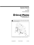
Operator’s Manual
TSF660
Front Fold Boom Sprayer
Manufacturing, Inc.
www.greatplainsmfg.com
!
Read the operator’s manual entirely. When you see this symbol, the subsequent
instructions and warnings are serious - follow without exception. Your life and
the lives of others depend on it!
23113
Cover illustration may show optional equipment not supplied with standard unit.
© Copyright 2009
Printed 08/31/2009
500-644M
Table of Contents
Important Safety Information . . . . . . . . . . . . . . . . 1
Wear Protective Equipment . . . . . . . . . . . . . . . 5
Handle Chemicals Properly . . . . . . . . . . . . . . . 6
Safety Decals . . . . . . . . . . . . . . . . . . . . . . . . . . 8
Introduction . . . . . . . . . . . . . . . . . . . . . . . . . . . . . 13
Description of Unit. . . . . . . . . . . . . . . . . . . . . . 13
Intended Usage . . . . . . . . . . . . . . . . . . . . 13
Models Covered . . . . . . . . . . . . . . . . . . . . 13
Using This Manual . . . . . . . . . . . . . . . . . . . . . 13
Definitions. . . . . . . . . . . . . . . . . . . . . . . . . 13
Owner Assistance . . . . . . . . . . . . . . . . . . . . . . 14
Preparation and Setup . . . . . . . . . . . . . . . . . . . . 15
Before You Start . . . . . . . . . . . . . . . . . . . . . . . 15
Hitching Tractor to Sprayer . . . . . . . . . . . . . . . 15
Hydraulic Pump Setup . . . . . . . . . . . . . . . . . . 17
Hydraulic Hook-Up . . . . . . . . . . . . . . . . . . . . . 18
Axle Wheel Spacing Adjustment. . . . . . . . . . . 19
Quad-Jet Agitators . . . . . . . . . . . . . . . . . . . . . 20
Raven SCS 440 . . . . . . . . . . . . . . . . . . . . . . . 20
Electrical Connections . . . . . . . . . . . . . . . . . . 20
Adjustments Before Going to the Field . . . . . . 21
Hydraulic Driven Pumps . . . . . . . . . . . . . . 21
Field Adjustments . . . . . . . . . . . . . . . . . . . . . . 22
Boom Height. . . . . . . . . . . . . . . . . . . . . . . 22
Agitation Adjustments. . . . . . . . . . . . . . . . 22
Tank Straps. . . . . . . . . . . . . . . . . . . . . . . . 22
Operating Instructions . . . . . . . . . . . . . . . . . . . . 23
Operating Checklist. . . . . . . . . . . . . . . . . . . . . 24
Plumbing Operations . . . . . . . . . . . . . . . . . . . 25
Boom Operations . . . . . . . . . . . . . . . . . . . . . . 27
Boom Folding Procedure . . . . . . . . . . . . . . . . 28
Boom Folding . . . . . . . . . . . . . . . . . . . . . . 28
Boom Unfolding . . . . . . . . . . . . . . . . . . . . 28
Locking System. . . . . . . . . . . . . . . . . . . . . . . . 29
Break Away Spring . . . . . . . . . . . . . . . . . . . . . 29
Leveling Boom . . . . . . . . . . . . . . . . . . . . . . . . 30
Filling Tank Procedures. . . . . . . . . . . . . . . . . . 31
Using Handwash Tank . . . . . . . . . . . . . . . . . . 31
Operating Whirlfilter® . . . . . . . . . . . . . . . . . . . 31
Transporting . . . . . . . . . . . . . . . . . . . . . . . . . . 32
Parking . . . . . . . . . . . . . . . . . . . . . . . . . . . . . . 32
Tank Rinse and Flush System. . . . . . . . . . . . . 34
Inductor (Optional Equipment) . . . . . . . . . . . . 35
Raven G1 Autoboom (Optional Equipment) . . 35
Adjustments. . . . . . . . . . . . . . . . . . . . . . . . . . . . . 37
Boom Height . . . . . . . . . . . . . . . . . . . . . . . . . . .37
Nozzle Pressure . . . . . . . . . . . . . . . . . . . . . . . 37
Tank Straps . . . . . . . . . . . . . . . . . . . . . . . . . . . 37
Manual Pressure Adjustment Valve . . . . . . . . 37
Agitation Adjustment . . . . . . . . . . . . . . . . . . . . 39
Operating Whirlfilter® . . . . . . . . . . . . . . . . . . . 39
Clean-out the solution Whirlfilter® . . . . . . 39
Elevator Slide Adjustment . . . . . . . . . . . . . . . . 40
Troubleshooting. . . . . . . . . . . . . . . . . . . . . . . . . . 41
Maintenance and Lubrication. . . . . . . . . . . . . . . 43
Sprayer/Boom Maintenance . . . . . . . . . . . . . . 43
Equipment Cleanup. . . . . . . . . . . . . . . . . . . . . 43
General Information . . . . . . . . . . . . . . . . . . . . 43
Pump Maintenance and Repair. . . . . . . . . . . . 43
Ace Pumps . . . . . . . . . . . . . . . . . . . . . . . . 43
Ace Hydraulic Pump Seal Replacement. . 44
Shear Bolt Replacement . . . . . . . . . . . . . . . . . 45
Storage . . . . . . . . . . . . . . . . . . . . . . . . . . . . . . 45
Lubrication . . . . . . . . . . . . . . . . . . . . . . . . . . . 46
Options . . . . . . . . . . . . . . . . . . . . . . . . . . . . . . . . . 49
Chemical Inductor . . . . . . . . . . . . . . . . . . . . . . 49
Foam Marker . . . . . . . . . . . . . . . . . . . . . . . . . . 49
Raven G1 Autoboom. . . . . . . . . . . . . . . . . . . . 49
Pumps . . . . . . . . . . . . . . . . . . . . . . . . . . . . . . . 50
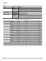
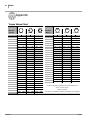
Specifications and Capacities . . . . . . . . . . . . . . 51
Tire Inflation Chart . . . . . . . . . . . . . . . . . . . . . 51
Appendix . . . . . . . . . . . . . . . . . . . . . . . . . . . . . . . 52
Torque Values Chart . . . . . . . . . . . . . . . . . . . . 52
Warranty . . . . . . . . . . . . . . . . . . . . . . . . . . . . . 53
© Copyright 2009 All rights Reserved
Great Plains Manufacturing, Inc. provides this publication “as is” without warranty of any kind, either expressed or implied. While every precaution has been taken in the
preparation of this manual, Great Plains Manufacturing, Inc. assumes no responsibility for errors or omissions. Neither is any liability assumed for damages resulting from
the use of the information contained herein. Great Plains Manufacturing, Inc. reserves the right to revise and improve its products as it sees fit. This publication describes
the state of this product at the time of its publication, and may not reflect the product in the future.
Great Plains Manufacturing, Incorporated Trademarks
The following are trademarks of Great Plains Mfg., Inc.: Application Systems, Ausherman, Land Pride, Great Plains
All other brands and product names are trademarks or registered trademarks of their respective holders.
Printed in the United States of America.
9/1/2009
500-644M
Important Safety Information 1
Important Safety Information
Look for Safety Symbol
The SAFETY ALERT SYMBOL indicates there is
a potential hazard to personal safety involved and
extra safety precaution must be taken. When you
see this symbol, be alert and carefully read the
message that follows it. In addition to design and
configuration of equipment, hazard control and
accident prevention are dependent upon the
awareness, concern, prudence and proper training of personnel involved in the operation,
transport, maintenance and storage of
equipment.
!
Be Aware of Signal Words
Signal words designate a degree or level of hazard seriousness.
DANGER indicates an imminently hazardous situation which, if not avoided, will result in death or
serious injury. This signal word is limited to the
most extreme situations, typically for machine
components that, for functional purposes, cannot
be guarded.
! DANGER
WARNING indicates a potentially hazardous situation which, if not avoided, could result in death or
serious injury, and includes hazards that are exposed when guards are removed. It may also be
used to alert against unsafe practices.
! WARNING
CAUTION indicates a potentially hazardous situation which, if not avoided, may result in minor or
moderate injury. It may also be used to alert
against unsafe practices.
! CAUTION
9/1/2009
500-644M
2
TSF660
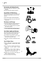
Be Familiar with Safety Decals
▲ Read and understand “Safety Decals,” page 8,
thoroughly.
▲ Read all instructions noted on the decals.
Keep Riders Off Machinery
Riders obstruct the operator’s view. Riders could
be struck by foreign objects or thrown from the
machine.
▲ Never allow children to operate equipment.
▲ Keep all bystanders away from machine dur-
ing operation.
Shutdown and Storage
▲ Fold Front Fold Boom Sprayer, put tractor in
park, turn off engine, and remove the key.
▲ Secure Front Fold Boom Sprayer using blocks
OFF
and supports provided.
▲ Detach and store Front Fold Boom Sprayer in
an area where children normally do not play.
Use Safety Lights and Devices
Slow-moving tractors and towed implements can
create a hazard when driven on public roads.
They are difficult to see, especially at night.
▲ Use flashing warning lights and turn signals
whenever driving on public roads.
▲ Use lights and devices provided with imple-
ment.
Use A Safety Chain
▲ Use a safety chain to help control drawn
machinery should it separate from tractor
drawbar.
▲ Use a chain with a strength rating equal to or
greater than the gross weight of towed
machinery.
▲ Attach chain to tractor drawbar support or
other specified anchor location. Allow only
enough slack in chain to permit turning.
▲ Replace chain if any links or end fittings are
broken, stretched or damaged.
▲ Do not use safety chain for towing.
500-644M
9/1/2009
Important Safety Information 3
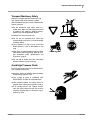
Transport Machinery Safely
Maximum transport speed for implement is 20
mph. Some rough terrains require a slower
speed. Sudden braking can cause a towed load to
swerve and upset.
▲ Do not exceed 20 mph. Never travel at a
speed which does not allow adequate control
of steering and stopping. Reduce speed if
towed load is not equipped with brakes.
▲ Comply with state and local laws.
▲ Do not tow an implement that, when fully
loaded, weighs more than 1.5 times the weight
of towing vehicle.
▲ Carry reflectors or flags to mark Front Fold
Boom Sprayer in case of breakdown on the
road.
▲ Keep clear of overhead power lines and other
obstructions when transporting. Refer to transport dimensions under “Specifications and
Capacities,” page 51.
▲ Do not fold or unfold the Front Fold Boom
Sprayer while the tractor is moving.
Avoid High Pressure Fluids
Escaping fluid under pressure can penetrate the
skin, causing serious injury.
▲ Avoid the hazard by relieving pressure before
disconnecting hydraulic lines.
▲ Use a piece of paper or cardboard, NOT
BODY PARTS, to check for suspected leaks.
▲ Wear protective gloves and safety glasses or
goggles when working with hydraulic systems.
▲ If an accident occurs, see a doctor immedi-
ately. Any fluid injected into the skin must be
surgically removed within a few hours or gangrene may result.
9/1/2009
500-644M
4
TSF660
Practice Safe Maintenance
▲ Understand procedure before doing work. Use
proper tools and equipment. Refer to this manual for additional information.
▲ Work in a clean, dry area.
OFF
▲ Fold the Front Fold Boom Sprayer, put tractor
in park, turn off engine, and remove key before
performing maintenance.
▲ Make sure all moving parts have stopped and
all system pressure is relieved.
▲ Allow Front Fold Boom Sprayer to cool com-
pletely.
▲ Disconnect battery ground cable (-) before
servicing or adjusting electrical systems or
before welding on Front Fold Boom Sprayer.
▲ Inspect all parts. Make sure parts are in good
condition and installed properly.
▲ Remove buildup of grease, oil or debris.
▲ Remove all tools and unused parts from Front
Fold Boom Sprayer before operation.
Prepare for Emergencies
▲ Be prepared if a fire starts.
▲ Keep a first aid kit and fire extinguisher handy.
▲ Keep emergency numbers for doctor, ambu-
lance, hospital and fire department near
phone.
911
Tire Safety
Tire changing can be dangerous and should be
performed by trained personnel using correct
tools and equipment.
▲ When inflating tires, use a clip-on chuck and
extension hose long enough for you to stand
to one side–not in front of or over tire assembly. Use a safety cage if available.
▲ When removing and installing wheels, use
wheel-handling equipment
weight involved.
500-644M
adequate
for
9/1/2009
Important Safety Information 5
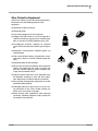
Wear Protective Equipment
Great Plains advises all users of chemical pesticides or
herbicides to use the following personal safety
equipment.
▲ Waterproof, wide-brimmed hat
▲ Waterproof apron.
▲ Face shield, goggles or full face respirator.
▲ Goggles with side shields or a full face respirator is
required if handling or applying dusts, wettable powders, or granules or if being exposed to spray mist.
▲ Cartridge-type respirator approved for pesticide
vapors unless label specifies another type of respirator.
▲ Waterproof, unlined gloves. Neoprene gloves are
recommended.
▲ Cloth coveralls/outer clothing changed daily; water-
proof items if there is a chance of becoming wet with
spray
▲ Waterproof boots or foot coverings
▲ Do not wear contaminated clothing. Wash protective
clothing and equipment with soap and water after
each use. Personal clothing must be laundered separately from household articles.
▲ Clothing contaminated with certain pesticides must
be destroyed according to state and local regulations. Read chemical label for specific instructions.
▲ Wear clothing and equipment appropriate for the job.
Avoid loose-fitting clothing.
▲ Prolonged exposure to loud noise can cause hear-
ing impairment or loss. Wear suitable hearing protection such as earmuffs or earplugs.
▲ Avoid wearing radio headphones while operating
machinery. Operating equipment safely requires the
full attention of the operator.
9/1/2009
500-644M
6
TSF660
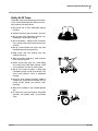
Handle Chemicals Properly
▲ Read and follow chemical manufacturer’s
instructions.
▲ Wear protective clothing.
▲ Handle all chemicals with care.
▲ Spray only with acceptable wind conditions.
Wind speed must be below 5 mph. Make sure
wind drift of chemicals will not affect any surrounding land, people or animals.
▲ Never wash out the sprayer tank within 100
▲ Agricultural chemicals can be dangerous.
feet of any freshwater source or in a car wash.
Improper use can seriously injure persons,
animals, plants, soil and property.
▲ Rinse out the tank. Spray rinse water on last
field sprayed.
▲ Inhaling smoke from any type of chemical fire
is a serious health hazard.
▲ Store or dispose of unused chemicals as
specified by the chemical manufacturer.
▲ Before adding chemical to the tank, make
sure tank is at least half full. Do not pour concentrate into an empty tank.
▲ Never leave fill hose attached to the sprayer
after filling tank. Chemicals in tank can siphon
out of tank and contaminate freshwater
source.
▲ Always keep hand-wash tank filled with clean
water and have soap available in case of an
emergency. Immediately and thoroughly flush
any area of the body that is contaminated by
chemicals.
▲ Do not touch sprayer components with mouth
or lips.
▲ If chemical is swallowed, carefully follow the
chemical manufacturer’s recommendations
and consult with a doctor.
▲ If persons are exposed to a chemical in a way
that could affect their health, consult a doctor
immediately with the chemical label or container in hand. Any delay could cause serious
illness or death.
▲ Dispose of empty chemical containers prop-
erly. By law rinsing of the used chemical container must be repeated three times. Puncture
the container to prevent future use. An alternative is to jet-rinse or pressure rinse the container.
▲ Wash hands and face before eating after
working with chemicals. Shower as soon as
spraying is completed for the day.
500-644M
9/1/2009
Important Safety Information 7
Safety At All Times
Thoroughly read and understand the instructions
in this manual before operation. Read all instructions noted on the safety decals.
▲ Be familiar with all Front Fold Boom Sprayer
functions.
▲ Operate machinery from the driver’s seat only.
▲ Do not leave Front Fold Boom Sprayer unat-
tended with tractor engine running.
▲ Do not dismount a moving tractor. Dismount-
ing a moving tractor could cause serious injury
or death.
▲ Do not stand between the tractor and Front
Fold Boom Sprayer during hitching.
▲ Keep hands, feet and clothing away from
power-driven parts.
▲ Wear snug-fitting clothing to avoid entangle-
ment with moving parts.
▲ Watch out for wires, trees, etc., when folding
and raising Front Fold Boom Sprayer. Make
sure all persons are clear of working area.
▲ Do not turn tractor too tightly, causing Front
Fold Boom Sprayer to ride up on wheels. This
could cause personal injury or equipment
damage.
▲ Use only water without pesticides added to
calibrate the sprayer.Do not exceed the calibrated sprayer speed and pressure when
operating.
▲ Spray with the boom in the unfolded position
only.
▲ The boom has many pinch points during field
operation and folding. Keep all bystanders
away.
9/1/2009
500-644M
8
TSF660
Safety Decals
▲ When ordering new parts or components, also
Your implement comes equipped with all safety
decals in place. They were designed to help you
safely operate your implement.
▲ To install new decals:
request corresponding safety decals.
1.
Clean the area where the decal is to be
placed.
2.
Peel backing from decal. Press firmly on
surface, being careful not to cause air
bubbles under decal.
▲ Read and follow decal directions.
▲ Keep all safety decals clean and legible.
▲ Replace all damaged or missing decals. Order
new decals from your Great Plains dealer.
Refer to this section for proper decal placement.
818-055C
20410
Slow Moving Vehicle Label
Middle rear of center section, one total
838-265C
Amber Reflectors
Front of center section, both ends, two total
20410
500-644M
9/1/2009
Important Safety Information 9
818-188C
13862
Warning! Excessive Speed Hazard
Front of tongue, one total
818-339C
Warning! High Pressure Fluid Hazard
Side of tank frame and rear center of
boom center section, two total
13862
818-265C
Amber Reflector
Front and rear {both sides} four total
9/1/2009
500-644M
10
TSF660
818-323C
Danger! Possible Chemical Hazard
Front of tank frame and rear center
of boom center section, two total
13863
818-324C
Caution! To Avoid Injury or Machine Damage
Front of tank frame, one total
24033
818-548C
13864
500-644M
Warning! To Prevent Serious Injury or Death
On each side of tank frame, two total
9/1/2009
Important Safety Information 11
818-367C
20410
Danger! Electrocution Hazard
Middle rear of center section, one total
818-696C
13863
Warning! Water Contamination Hazard
Side of tank frame, one total
13838
818-365C (SN A1082N-)
848-347C (SN A1083N+)
Caution! Tire inflation & wheel bolt torquing information
(13.6 x 38 or 320/85R38 wheel rims), 0 or 2 total
818-864C
20410
9/1/2009
Danger! Crushing Hazard
Rear center and both ends front side of center section,
three total
500-644M
12
TSF660
818-798C
20278
Warning! Pinch Point
Decals at wing hinge points, front and back of booms, ten
total
818-467C
20278
Warning! Overhead Boom
Left and right wings, two total
818-303C
15763
Warning! Chemical Overflow
On chemical tank, one total
818-019C
20411
500-644M
Warning! Negative Tongue Weight
On tongue, one total
9/1/2009
Introduction 13
Introduction
Great Plains welcomes you to its growing family of
new product owners. This Front Fold Boom Sprayer has been designed with care and built by skilled
workers using quality materials. Proper setup,
maintenance and safe operating practices will
help you get years of satisfactory use from the
machine.
Description of Unit
The TSF660 sprayer is capable of spraying at
60’.The level float boom is fully suspended starting with vertical spring suspension in a 42”
hydraulic elevator which provides a wide range of
boom height adjustment along with gas shocks
that provide side-to-side stability.
Definitions
The following terms are used throughout this
manual.
Right-hand and left-hand as used in this manual
are determined by facing the direction the machine
will travel while in use unless otherwise stated.
IMPORTANT: A crucial point of information related to the preceding topic. For safe and correct operation, read and follow the directions
provided before continuing.
NOTE: Useful information related to the preceding
topic.
Intended Usage
Use these booms as part of a pressurized sprayer
system to apply liquid pesticides, herbicides or
fertilizers to production-agriculture crops only. Do
not modify sprayer for use with attachments other
than those approved by Great Plains.
Models Covered
TSF660
Using This Manual
This manual will familiarize you with safety, assembly, operation, adjustments, troubleshooting
and maintenance. Read this manual and follow
the recommendations to help ensure safe and efficient operation.
The information in this manual is current at printing. Some parts may change to assure top
performance.
9/1/2009
500-644M
14
TSF660
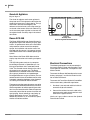
Owner Assistance
If you need customer service or repair parts, contact a Great Plains dealer. They have trained
personnel, repair parts and equipment specially
designed for Front Fold Boom Sprayer products.
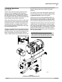
Refer to Figure 1
Your machine’s parts were specially designed and
should only be replaced with Front Fold Boom
Sprayer parts. Always use the serial and model
number when ordering parts from your Great
Plains dealer. The serial-number plate is located
on the front of the tank frame as shown.
Record your drill model and serial number here for
quick reference:
Model Number:__________________________
Serial Number: ___________________________
Figure 1
Serial Number Plate
23312
Your Great Plains dealer wants you to be satisfied
with your new machine. If you do not understand
any part of this manual or are not satisfied with the
service received, please take the following
actions.
1. Discuss the matter with your dealership service manager. Make sure they are aware of
any problems so they can assist you.
2. If you are still unsatisfied, seek out the owner
or general manager of the dealership.
3. For further assistance write to:
Product Support
Great Plains Mfg. Inc., Service Department
PO Box 5060
Salina, KS 67402-5060
500-644M
9/1/2009
Preparation and Setup 15
Preparation and Setup
Before You Start
Read and understand the owners manual for your
sprayer. A basic understanding of how the sprayer
works will aid in the assembly, setup and operation of your sprayer.
Perform these checks before setting up your
cross-fold boom.
1. Read and understand “Important Safety Information,” beginning on page 1.
2. Check that all working parts are moving freely, bolts are tight, and cotter pins are spread.
3. Check that all grease fittings are in place and
lubricated. Refer to “Lubrication,” page 46.
4. Check that all safety decals and reflectors are
correctly located and legible. Replace if damaged. Refer to “Safety Decals,” page 8.
Hitching Tractor to Sprayer
!
DANGER
!
DANGER
You may be severely injured or killed by being crushed
between the tractor and Front Fold Boom Sprayer. Do
not stand or place any part of your body between Front
Fold Boom Sprayer and moving tractor. Stop tractor
engine and set park brake before installing the hitch
pin.
Electrocution hazard. To prevent serious injury or
death from electric shock, keep clear of overhead power lines when transporting, folding or unfolding boom.
Boom is not grounded. Electrocution can occur without direct contact. Refer to transport dimensions under
“Specifications and Capacities”, page 51. Do not fold
or unfold boom while tractor is moving.
9/1/2009
500-644M
16
TSF660
A clevis hitch is used. Park the sprayer in an open,
flat area with the jack in the park position. See figure
2.
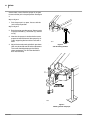
Refer to Figure 2
1. Park the sprayer in an open, flat area with the
jack in the park position.
Refer to Figure 3
2. Back the tractor up to the sprayer. Secure tractor
to sprayer with bolt (1), flat washer (2), and hex
nut (3).
3. Now that the sprayer is attached to the tractor,
prepare to level the frame of the sprayer by securely supporting the front of the frame with a
hoist.
13811
4. Adjust the frame by moving the hitch up or down.
Hitch may be turned over for further adjustment.
The frame should be sloping to the front by
about one degree. This will allow the fluid to
drain into the sump.
Figure 2
Jack In Parking Position
24497
Figure 3
Hitching Tractor to Sprayer
500-644M
9/1/2009
Preparation and Setup 17
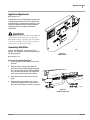
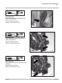
Hydraulic Pump Setup
The hydraulic motor used on all liquid pumps is a 7 gpm
(23 liter/min.) motor. If the tractor used on the sprayer
does not have the capabilities to adjust the remotes down
to this flow, then a Hydraulic Flow Divider Kit must be installed so that flow can be controlled to prevent operating
the pump at excessive speeds. See a Great Plains dealer
for more information.
1. Connect the hydraulic pump to the tractor remotes.
See “Hydraulic Pump Hookup” on page 18 for
details. If no limiter is required, skip to step 7.
DO NOT move the hydraulic lever into the neutral position while the hydraulic pump is running. To do so may
cause damage to the hydraulic pump.
Ace Pump Flow Limiter (Option)
The flow limiter (Great Plains part number 829-125C) is
a hydraulic device designed to shut off the flow of
hydraulic oil when a specified flow is exceeded. On tractors with LOAD SENSING (LS) Closed Center hydraulic
systems, this device limits the flow of oil to the Ace motor
and prevents failures due to misapplication.
Newer Case-IH, John Deere, New Holland, and CAT
tractors, present a great potential to turn the motors
beyond their rated speeds. Flows out of the hydraulic
valves can exceed 20 gpm while the motors are rated at
4-11 gpm. The flow limiter protects the Ace motor by
shutting off when hydraulic flows exceed the motor’s
capacity.
Figure 4
Ace Pump Flow Limiter
23395
Note: If the flow limiter stops the flow of oil to the motor:
6a) Move the hydraulic lever to the “Neutral” position. This removes the oil pressure from the flow
limiter and allows it to reset.
6b) Adjust the flow control to a lower flow position.
6c) Repeat step 5 and step 6.
Setting Pump Rate
7. To determine the correct setting of the flow rate, start
out with the hydraulic flow control valve at minimum
flow for the outlets that operate the pump.
The flow limiter should not be used on OPEN Center or
PRESSURE COMPENSATING Closed Center hydraulic
systems. The flow limiter should not be used with a
restrictor orifice.
8. With water in the sprayer tank and in the pump, place
the hydraulic lever in the float position.
Flow Limiter Installation
2. Install the flow limiter in the inlet port of the Ace
motor.
10. Start the tractor and engage the pump by placing the
hydraulic lever in the down (forward) position.
3. Shut off boom and agitation valves on the sprayer to
deadhead the sprayer pump flow.
4. Adjust the flow control on the tractor to the minimum
flow setting (typically a “turtle” icon).
5. Move the hydraulic lever to the “Lower/Retract” position.
6. Adjust the flow control on the tractor until the sprayer
system deadhead pressure is 80 psi.
9. Open up the sprayer flow control valve to its maximum setting.
11. Once the system builds pressure, close the agitation
valve, shut off the boom section switches, and close
the throttling valves (if applicable).
12. The pump is now at dead head pressure and the
hydraulic control valve must be adjusted so that the
spray pressure reaches 80 PSI maximum on the
nozzle pressure gauge. This process should be done
with the tractor throttle set at normal operating
speed. Mark this setting on the hydraulic control
valve for future reference.
13. Open up the agitation valve.
9/1/2009
500-644M
18
TSF660
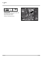
Hydraulic Hookup
The standard TSF660 sprayer has a single hydraulic connection at the hitch. Each cart hydraulic function is served
by an electro-hydraulic control valve at boom center.
If an optional hydraulic pump is installed, there is a second hydraulic connection for the pump, which is located
near the hitch.
Refer to Hose Label
Both hose sets have labels for flow conventions. These labels use cylinder Base/Extend and Rod/Retract icons.
Be sure to connect these to the matching tractor remotes,
so that when remote levers are activated as described in
this manual:
a. booms move in the described directions, and
b. pump flow is forward and not reversed.
Sprayer Control Hydraulic Hookup
If the sprayer has a hydraulic pump, and the tractor has
only one circuit capable of continuous flow or only one capable of adjustable continuous flow, reserve that circuit for
the pump, and use another for the main sprayer functions.
1. Connect the main sprayer hydraulic hoses to suitable
tractor remotes. They are easily identified, as they
pass behind the pump.
Hydraulic Pump Hookup
The hydraulic motor used on all liquid pumps is a 7 gpm
(23 liter/min.) motor. If the tractor used on the sprayer
does not have the capabilities to adjust the remotes down
to this flow, then a Hydraulic Flow Divider Kit must be installed so that flow can be controlled to prevent operating
the pump at excessive speeds. See a Great Plains dealer
for more information.
Hose Label
Outlet Port
Inlet Port
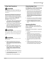
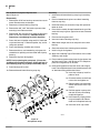
Refer to Ace Pump Connections
2. The pressure hose coming out of the tractor remotes
must be connected to the motor inlet port (“I” on current pumps; “A” on older pumps, Base end on hose
label), and the return line connected to the motor
outlet (“O” on current pumps, “B” on older pumps,
Rod end on hose label).
3. Before operating, place a stop in the neutral position
for the tractor hydraulics so that the hydraulic lever
can only be moved to the float and down positions.
Refer to the tractor’s operator’s manual or tractor
dealer on information for the neutral stop.
27270
Date Code
Motor Model (204N,206N,210N)
Ace Pump Connections
27141
Note: DO NOT move the hydraulic lever into the neutral
position while the hydraulic pump is running. To do
so may cause damage to the hydraulic pump.
4. See page 21 for setting flow rate.
500-644M
9/1/2009
Preparation and Setup 19
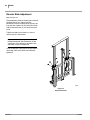
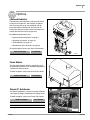
Axle Wheel Spacing Adjustment
!
CAUTION
Axle position must be located correctly to avoid excessive tongue weight or negative tongue weight which
could cause mechanical failure resulting in personal
injury.
Refer to Figure 5
The wheel spacing of the axle can also be adjusted for differing row spacings.
!
CAUTION
Do not adjust the wheel spacing wider than 120". To
do so may cause a falling axle hazard while the sprayer is in service.
24035
Figure 5
Sprayer Axle Assembly
9/1/2009
500-644M
20
TSF660
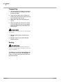
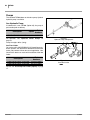
Quad-Jet Agitators
Refer to Figure 6
The Quad-Jet agitators are the two agitators in
the sprayer tank. Each agitator has four holes that
shoot jets of water out at a high velocity. The agitator head is oriented at 45 degrees, with
reference to the tank ends, so that the water jets
are aimed at the corners of the tank. Refer to Figure 22 to ensure proper agitation, make sure that
the agitator heads are always kept in the orientation shown.
Raven SCS 440
Figure 6
Tank Top View
Quad-Jet Agitator Head Orientation
11585
The Raven SCS 440 (Sprayer Control System) is
designed to improve the uniformity of spray applications. Its performance relies on the installation
and preventive maintenance of the complete
sprayer. An installation and service manual are
provided with this sprayer. It is important to read
and understand this manual before operating the
system.
Note: Refer to the Raven SCS 440 manual for
step-by-step instructions for installing and operating.
The SCS 440 system consists of a computerbased Control Console, a Speed Sensor, a turbine type Flow Meter and a motorized Control
Valve. The Console mounts directly in the cab of
the tractor for easy operator use. The Radar
Speed Sensor is mounted to the frame of the tractor or sprayer (wheel drive and speedometer
Drive Speed Sensors are also available.) The motorized Control Valve and Flow Meter mount to the
framework supporting the boom valves. Appropriate cabling is furnished for field installation.
The operator sets the target volume per area to be
sprayed and the SCS 440 automatically maintains
the flow regardless of vehicle speed or gear selection. A manual override switch allows the operator
to manually control flow for system check-out and
spot spraying. Actual volume per area being applied is displayed at all times. The SCS 440
additionally functions as an area monitor, speed
monitor and volume totalizer.
500-644M
Electrical Connections
The following equipment must be connected to
the tractor’s battery: Raven 440 Controller, Fasse
Valve Hydraulic Control Box, and Optional Foam
Marker Control.
To connect the Raven 440 Controller to the tractor
battery, see pages 7 and 8 in the Raven Installation and Service Manual.
To connect the Fasse Valve Hydraulic Control Box
to the tractor battery, follow the steps below.
1. Use the 6 ft, two-wire red and black cable to
connect the hydraulic controls.
2. Connect the red wire from each cable to the
positive terminal and the black wire from each
cable to the negative terminal.
Use the 6 ft gray cable to connect the Optional
Foam Marker Control.
9/1/2009
Preparation and Setup 21
Adjustments Before Going to the
Field
1. Securely hitch the sprayer to the tractor and fasten
the safety chain. Make sure the hitch is adjusted
so that the front of sprayer is 1 1/2” lower than the
rear so that liquid in the tank will drain to the sump.
2. Fill sprayer 1/2 full with water for calibrating purposes.
3. Hook-up the pump to the tractor. Engage the
pump slowly and check for any leaks.
4. Set the deadhead pressure of the pump at 80
P.S.I. depending on how the pump is driven.
Hydraulic Driven Pumps
a. To determine the correct flow rate to the hydraulic motor, start out with the hydraulic control valve set at a minimum flow, and the
hydraulic lever in the float position.
b. Open up the sprayer control valve to its maximum setting. (On the Raven 440 monitor, with
the power switch on, the rate switch must be
placed in the manual position, and the increase/decrease switch must be pushed to increase for 10-12 seconds.)
c. Start the tractor and engage the pump by
placing the hydraulic lever in the down position. Once the system builds pressure on the
nozzle pressure gauge, speed up the tractor
throttle to normal operating speed. Shut off
the boom section switches and close the agitation valve.
d. The pump is now at deadhead pressure and
the hydraulic control valve must be adjusted
up until the spray pressure reaches 80 P.S.I.
maximum on the nozzle pressure gauge.
Mark this setting on the hydraulic control valve
for future reference.
e. Open up the agitation valve.
5. Calibrate sprayer. Sprayer calibration (1) prepares
your sprayer for operation, and (2) diagnoses nozzle wear. This will give you optimum performance
from your nozzles and ensure accuracy from your
sprayer.
Equipment Needed:
• Calibration Container
• Calculator
• Stopwatch or wristwatch with second hand.
9/1/2009
Step 1
Measure off a 200’ course in the area to be
sprayed or in an area with similar surface conditions. Select the engine throttle setting and gear
that will be used when spraying. The starting
post should be far enough away to permit your
tractor/sprayer to reach desired spraying speed.
Hold that speed as you approach the “start”
marker, and check the time required to travel
through the course to the “end” marker. Repeat
the above procedure, and average the times that
were recorded. Use the following equation to determine the exact ground speed.
Speed (MPH) = Distance (ft.) x 60
Time (seconds) x 88
Example: MPH = 200 x 60
27 x 88
MPH = 12000
2376
MPH = 5.05
Step 2
Determine the application rate at which your
chemical should be sprayed. In determining
which spray nozzles to use with your sprayer, you
must know:
a.
b.
c.
d.
Nominal application pressure ____P.S.I.
Target application rate
____GPA
Target speed
____MPH
Nozzle spacing
____W (in)
Using this information, calculate the volume per
minute, per nozzle as follows:
GPM = GPA x MPH x W (nozzle spacing)
5,940
Example:
a. Nominal application pressure 30 P.S.I.
b. Target application rate
20 GPA
c. Target speed
5.0 MPH
d. Nozzle spacing
20 W (in)
GPM = 20 GPA x 5 MPH x 20 W (in) = .34
5,940
Using GPM .34 and pressure 30 P.S.I., you
would select a nozzle from your nozzle chart that
comes closest to providing the desired output.
500-644M
22
TSF660
Step 3
Turn on your sprayer and adjust the pressure. Operate the sprayer at desired pressure and catch the
discharge in the calibration container for one
minute. Divide 128 into the number of ounces
caught to determine gallons per minute (GPM) per
nozzle. 128 fluid ounces equals one gallon.
Example:
OPM (ounces per minute) ÷ 128 = GPM (gallons
per minute)
44 OPM ÷ 128 =.34 GPM
Step 4
Determine your nozzle spacing in inches.
Example: 1 nozzle every 20 inches.
Solution:
GPA (gallons per acre) = 5,940 x GPM(per nozzle)
MPH x W (nozzle spacing)
Example:
GPA = 5,940 x .34
5.05 x 20
GPA = 2020
101
GPA = 20
Field Adjustments
Boom Height
After calibrating the sprayer for the specific nozzle
that will be used at a desired pressure and tractor
speed, the main field adjustment is the boom height.
Depending on which type of nozzle is being used,
set the boom height so that the correct overlap for
that specific nozzle is achieved. If the crop canopy is
taller in some fields than others, adjust the boom
height accordingly. Refer to the Nozzle Charts in the
Application Guide to determine the height of the
boom.
Agitation Adjustments
The agitation valve is used to adjust the pressure to
the agitation nozzles in the tank. Refer to the agitation gauge, and adjust the pressure to a desired rate.
Different chemicals require different agitation pressures to keep the chemical in suspension. (See
chemical label)
Tank Straps
The tank straps that wrap around the sprayer tank
may become loose after the first few hours of operation. This occurs when the tank settles in the saddle.
Polyethylene tanks are especially susceptible to this.
Retighten the tank straps to secure the tank.
The above information will assure you of a check for
accurate application in the event there is an error in the
gauge, nozzle spacing, nozzle height, tractor speed or
nozzle wear. Since all tabulations are based on spraying water, conversion factors must be used when
spraying solutions which are heavier or lighter than
water.
If sprayer is equipped with a Raven 440 Automatic
Rate Controller, this simple calibration procedure will
also work for verifying speed and proper nozzle output.
All Raven 440 Control Systems require either wheel
drive speed sensor magnets or a radar speed sensor.
Calibration procedures for the speed sensor magnets
can be found in the Raven 440 manual. Calculation
procedures for radar speed sensors are included with
each radar unit dependent on make and model. Make
sure to follow initial programming instructions (Step 3)
of the Raven manual to select either SP1-(wheel drive
sensor), or SP2-(radar sensor).
500-644M
9/1/2009
Operating Instructions 23
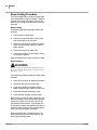
Operating Instructions
Basic Sprayer
Operating Procedures
!
DANGER
Read and follow chemical manufacturer’s instructions. Some chemicals can cause serious burns, lung
damage and even death.
1. Securely hitch the sprayer to the tractor and
fasten the safety chain. Make sure the hitch is
adjusted so that the liquid in the tank will drain
to the sump of the tank. Refer to Tractor/
Sprayer Hook-Up in the “Preparation and
Set-up” section on page 15.
2. Check the tire pressure in each tire. Refer to
the Tire Inflation Chart in the “Appendix”
section on page 51.
3. Lubricate the sprayer as needed. Refer to the
Lubrication portion of the “Maintenance and
Lubrication” section starting on page 46.
4. Hook-Up the pump to the tractor. Refer to
“Preparation and Set-up” on page 15 and
follow the instructions
5. When transporting the sprayer, DO NOT exceed 20 mph and DO NOT transport with
chemical in the tank.
6. NEVER allow anyone to ride on the sprayer.
7. Make sure all tank shut off valves are turned
on.
8. Calibrate sprayer with water only, not chemical and water. Calibrate with the sprayer tank
half full of water. Refer to the calibration procedures in the Application Guide.
9. Adjust the boom height required for the nozzles and spacing to be used. (Refer to nozzle
tables in the Application Guide.)
10. Check and clean, if necessary, pump, nozzles
and Whirlfilter®.
11. Check the sprayer initially and periodically for
loose bolts, pins and hose clamps. Check the
hoses, pumps, valves and fittings for leaks.
12. Make sure that the hand wash tank is full of
clean water.
9/1/2009
Make sure to read the label on the chemical
compound that is to be applied. It is the law.
13. Consider how the chemical will be stored and
how you will dispose of the chemical, according to the chemical label.
14. When calibrating, filling the tank, or working
around chemicals, wear protective clothing
that covers the body. Refer to “Personal Safety Equipment” on page 5. Have soap and
clean water available to wash any exposed areas. Never open a container with your bare
hands.
15. When filling the sprayer, it is better to mix the
chemical in the field where it is to be applied.
Position the sprayer 100 feet from any well or
other water source before mixing the chemical.
16. By law, you must repeat the rinsing of the
chemical container 3 times. The container
should then be punctured to prevent future
use. An alternative is to jet-rinse or pressure
rinse the container.
17. Check the condition of hoses and connections frequently. Release system pressure
before working on the sprayer by shutting off
the pump and flipping the individual boom
section switches on the control box. Always
wear rubber gloves when making repairs or
adjustments.
18. Apply spray when the wind is 5 m.p.h. or less.
Minimize drift by using nozzle tips with the
largest practical openings and by operating
the sprayer boom at the lowest practical
height and lowest practical pressure.
19. Drive at the same speed you used in your calibration. Refer to Application Guide. Keep
your sprayer calibrated.
20. If possible work crosswise to the wind, starting from the downwind side of the field. Do
this so you won’t ever be heading directly into
chemical fumes.
500-644M
24
TSF660
21. Take note of adjoining crops, houses, gardens, people, etc.
22. When you are finished spraying, empty the
tank and flush the sprayer with water, including the pump, the nozzles and the bypass line
from the throttling valves. Properly store the
chemical emptied from the tank or dispose of
it by the recommendations on its label.
23. When turning at the end of a field, make sure
you are correct on the rows so that the boom
will not overlap on crop previously sprayed.
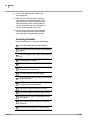
Operating Checklist
Each time the sprayer is used, check the following:
Check tire pressure, wear and overall condition.
Check the tractor’s brakes to make sure they operate
properly.
Make sure all lights and turn signals are working properly.
Lubricate sprayer as needed.
Booms must be locked in place before transporting.
Inspect tank. Make sure the hitch is adjusted so that
the solution drains to the sump.
Use safety equipment as listed on page 5.
Fill with water and calibrate sprayer BEFORE adding
chemical to the tank.
Check the position of the ball valves in the plumbing to
see if they are in the correct position.
Check hoses, pumps and valves for any leaks.
Check nozzle pattern for streaks and non-uniformity.
Check the sprayer initially and periodically for loose
bolts and pins.
Follow “Important Safety Information” on page 4 of
this Manual.
Make sure the handwash tank is full of clean water.
500-644M
9/1/2009
Operating Instructions 25
spective Boom Section and is sprayed out the individual
nozzles. Refer to page 26 for a layout of the boom
plumbing.
Plumbing Operations
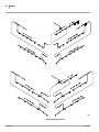
Refer to Figure 7
Figure 6 shows the basic plumbing diagram for the
sprayer. A basic knowledge of how the sprayer is
plumbed will help you to understand how to operate
your Great Plains Sprayer. Throughout this manual,
the components on this diagram will be described with
the terminology labeling these components.
Fluid is drawn out of the sump in the tank and passes
through the pump. From the pump it passes through
the solution whirlfilter® and filters out or grinds up all
undissolved chemical and solid particles. The fluid
then passes through both the Flow Meter and the Bypass Control Butterfly Valve.
The Bypass Control Butterfly Valve controls how much
fluid goes to the boom. This is regulated by the Raven
SCS 440 controller. The fluid passes through the Flow
Meter and proceeds to the 3-Way Boom Manifold
valves. If a Boom Valve is on, the fluid passes to its per-
The agitation can be set by adjusting the agitation pressure valve while the pump is at operating speed. Refer
to Application Guide to adjust the agitation.
There are tank shut off valves everywhere there is an
outlet from the tank so that if there is a leak, the source
can be shut off and the chemical spill reduced. These
valves need to be wide open when the sprayer is in use.
To operate the hydraulic pump, first make sure that the
hydraulic hoses are routed correctly so that the pump
turns in the correct direction. See the “Tractor/Hydraulic
Pump Hook-Up” on page 17, for more details. To run the
pump, push the hydraulic lever in the “down” position.
When you want to stop the pump, push the hydraulic lever in the “float” position.
IMPORTANT: Do not move the hydraulic lever to the
neutral position while the hydraulic pump is running.
To do so may cause damage to the hydraulic pump.
24437
Figure 7
Plumbing Diagrams Polyethylene Tank
9/1/2009
500-644M
26
TSF660
24438
Boom Plumbing Schematic
500-644M
9/1/2009
Operating Instructions 27
Boom Operations
2007+ Sprayer Hydraulics
On newer sprayers, the hydraulics use a “live” system.
The tractor hydraulic pump may be left on during sprayer
operations. This requires 5-to-8 gpm flow.
14
The console toggle switches move up and down from
center off, and are auto-return. They must be held up or
down until an operation is complete.
2006- Sprayer Hydraulics
The tractor circuit is engaged only during the operation,
and the tractor lever determines the direction of cylinder
movement.
The console switches move only up, are detented, and remain in the selected position until moved. The switch may
be operated before or after lever movement.
Refer to Figure 8
The “live” hydraulic controls come standard to operate
with “closed center” tractor hydraulics. To be used with an
“open center” system a conversion kit must be purchased
(part no. 833-427C). To install the conversion kit, remove
the plug from the end of the valve block (#14) located on
the top of the center boom section. Install the conversion
valve and coil into this location. Plug the electrical cable
into the open plug on the valve harness and the conversion is complete.
Figure 8
Fasse Valve Block
29639
Elevator Raising/Lowering
The elevator lifts and lowers the center section of the
boom, which raises and lowers the entire boom.
Refer to Figure 9
Lifting is performed by a hydraulic cylinder controlled by a
solenoid valve, which in turn is controlled by an up-down/
center-stop switch 1 on the boom control panel in the
tractor cab.
The elevator is fully raised for folding.
Lowering is by gravity retraction of the cylinder. When the
switch is toggled down, the hydraulic circuit is put in float.
Lifting and lowering speeds may differ.
Boom Height
After calibrating the sprayer for the specific nozzle to be
used at a desired pressure and tractor speed, the main
field adjustment is the boom height.
Depending on which type of nozzle is being used, set the
boom height so that the correct overlap for that specific
nozzle is achieved. If the crop canopy is taller in some
9/1/2009
1
Figure 9
Elevation Switches
27276
fields than others, adjust the boom height accordingly.
Refer to the Nozzle Charts in the Application Guide to
determine the height of the boom.
In center-off, the elevator stays at the current position. In
normal field operations, the elevator is set to the desired
height, and left there for the field. Typically this is about
20in (51cm) above the crop canopy.
As necessary, wings are raised and lowered at turns by
the operator, and adjusted to accommodate uneven terrain. The optional Autoboom system is useful on irregular
terrain.
500-644M
28
TSF660
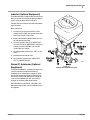
Boom Folding Procedure
The Front Folding Boom is hydraulically operated,
and is controlled by a single valve block. There are
controls for the vertical elevation, left and right
boom tilt, left and right inner fold and left and right
outer fold.
Boom Folding
The following procedure should be used to fold
the boom.
1. Raise elevator to top position.
2. Fold left and right outer booms 180˚. Make
sure outer booms snap into locks.
3. Raise left and right tilt to uppermost position.
Make sure lock plunger moves up, locking
boom in place.
4. Fold left and right inner booms 90˚.
5. Lower left and right tilt so the booms rest on
the transport supports.
Note: Outer booms will not lock if booms are tilted.
Boom Unfolding
!
WARNING
Negative tongue weight. Do Not unfold the booms if
the sprayer is unhooked from tractor with the sprayer
tank empty or low.
The following procedure should be used to unfold
the boom.
1. Raise left and right tilt to uppermost position.
2. Unfold left and right inner booms 90˚.
3. Lower left and right tilt to lowest position.
Make sure lock plunger lowers out of the way.
4. Unfold left and right outer booms 180˚.
5. Lower elevator to proper spraying height.
Normal boom use may shift the outer boom support locks along the inner section. When properly
adjusted, the outer arm plate will snap into the
gap between the lock plates, and the holes line
up. Loosen the U-bolts and reposition brackets as
necessary. Adjust cable tension so the plunger is
out of the way when boom is unfolded.
Make sure outer boom cylinder pressure is released and lock plunger is free to move up and
down before unfolding boom.
500-644M
9/1/2009
Operating Instructions 29
Locking System
Refer to Figure 10
The TSF660 has a locking system for automatic
boom locking during folding and transport. For
proper folding, the boom-lock cable must be tight
enough that the lock arms just clear their stops
when unfolded and rest secure against the stop
when folded.
Lock Arms
21760
Figure 10
Locking System
Refer to Figure 11
To adjust the tension on the boom-lock cable,
loosen jam nut and turn clevis.
21761
Figure 11
Boom-Lock Cable
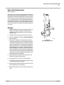
Break Away Spring
Refer to Figure 12
Periodically check that break-away springs are
compressed to 5 1/2 inches. Adjust spring by turning mounting nut under spring.
22952
Figure 12
Break-Away Spring
9/1/2009
500-644M
30
TSF660
Leveling Boom
!
WARNING
Pinch point hazard. Your fingers, hands or arms could
be seriously injured or severed if caught in the folding
boom sections. Shut off tractor and remove key before
adjusting shims.
Note: The boom sections must be level across the
span for even spraying.
Refer to Figure 13
To adjust the inner arm place supports under
boom and loosen bolts holding plate (A) at the top
of the pivot. Add or remove shims as necessary
and retighten bolts.
21762
Figure 13
Shims
500-644M
9/1/2009
Operating Instructions 31
Filling Tank Procedures
!
CAUTION
When filling the sprayer tank, use a check valve or
anti-siphon device to prevent the solution in the tank
from infiltrating into the fresh water source and contaminating it.
Your Great Plains Sprayer fills the tank from the
bottom of the tank and uses a standard 2 inch
Cam-Lock coupler to connect to the freshwater
hose. A 1 1/2 inch Cam-Lock coupler is also available as an accessory. Refer to "Quick Fill
Assembly" in the parts manual.
1.
To fill the tank, hook up the freshwater hose
to the quick-fill Cam-Lock coupler with the
quick-fill ball valve in the closed position.
2. Turn the water on and open the quick-fill ball
valve for the freshwater to enter the tank.
When using a positive displacement pump to
fill the tank, open the quick fill ball valve first
and then pump water into the tank.
!
CAUTION
Do not add the chemical until you are at the field, just
prior to spraying. When you add the chemical, follow
the manufacturer’s instructions for mixing the spray
solution in order to achieve the desired application
rate.
!
CAUTION
Read the manufacturer’s label carefully before handling chemicals.
3. Before you add the chemical to the tank,
make sure the tank is at least one half full.
The concentrate should not be poured into an
empty tank.
Using Handwash Tank
In the event when an accident occurs and chemical is spilled on your skin or in your eyes, use the
Handwash Tank to flush away the chemical.
1. Open the tank valve and use the hose to direct
the clean water on all contaminated areas.
Wash all areas of skin that has been contaminated with soap and water. To flush your
eyes, point the hose and water stream upward
while you lower your eye into the stream of
flowing water.
2. Close the tank valve and refill the handwash
tank with fresh water when you are finished.
3. Periodically refill the handwash tank with
fresh water. Always keep the handwash tank
clean.
Operating Whirlfilter®
There is one Whirlfilter® on your Great Plains
Sprayer. The Whirlfilter® filters the chemical solution being sprayed.
To clean-out the solution Whirlfilter®, proceed with
the following:
1. Fill the sprayer tank with water and turn the
pump on.
2. With the pump running, slowly open the
clean-out valve and allow the grit to flow out
into a bucket. Clean out the solution Whirlfilter® only when the sprayer tank is filled with
water and no chemical has been added.
3. Close the clean-out valve and turn off the
pump.
4. Dispose of the grit and water in the same
manner described on the manufacturer’s label
of the latest chemical used in the sprayer.
4. Keep the spray solution away from all skin.
Wear protective clothing and goggles. If the
solutions comes in contact with the body,
wash off the contaminated area with soap
and water.
5. Keep chemical containers low when pouring.
6. Let the wind blow fumes and dust away from
you while pouring the chemical.
7. Do not smoke while handling chemicals.
9/1/2009
500-644M
32
TSF660
Transporting
1. Park your sprayer in an open area where you
will not hit power lines, buildings, etc. when
the boom is folded.
2. Make sure the safety chain is securely fastened to the tractor draw bar and the retaining
clip is fastened to the hitch pin.
3. Never allow riders when transporting the
sprayer.
4. When transporting your sprayer, be sure to
watch the height clearances of your folded
boom to prevent damage to the boom and
possible injury.
!
DANGER
Contact with electrical power lines can cause death by
electrocution.
5. Do not exceed 20 mph transporting your
sprayer.
6. Do not transport sprayer while filled with
chemical mixture.
Parking
!
WARNING
Negative tongue weight. Do Not unhook the sprayer
from tractor with the sprayer tank empty or low with
the booms unfolded.
The following list should be conducted when you
want to unhitch your sprayer. See “Storage” on
Page 45, for more information on long term storage of your sprayer.
500-644M
9/1/2009
Operating Instructions 33
Refer to Figures 14 and 15
1. Remove the jack from the transport position
and move to the parking position.
2. If the ground is soft, place a board or plate under the jack to widen the ground contact area.
3. Extend the jack until the weight of the tongue
is off the tractor drawbar and is supported by
the jack.
4. Unplug the hydraulic lines from the hydraulic
pump.
5. Remove the hitch pin and safety chain from
the tractor drawbar.
NOTE: Refer to “Hitching Tractor to Sprayer,” on Page 15, when you are preparing to
hitch the sprayer to the tractor.
13811
Figure 14
Jack In Parking Position
NOTE: If the sprayer is being hitched up and
operated for the first time, it is important to follow the safety, set up, adjustment, and operating information in the front of this manual
23316
Figure 15
Jack In Transport Position
9/1/2009
500-644M
34
TSF660
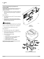
Tank Rinse and Flush System
The Tank Rinse and Flush is a factory installed
feature that compliments the Boom Flush option.The Tank Rinse and Flush feature will use the
fresh water in the 50 gallon flush tank to rinse out
the main sprayer tank in the field.
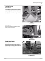
Refer to Figure 16
Before operation make sure the flush tank is filled
with fresh, clean water. To operate the Tank Rinse
and Flush, refer to the following instructions:
1. Completely empty the chemical in the main
sprayer tank by turning the agitation off the
last pass and spraying it out in the field.
2. Make sure all boom valves and pump are
turned off.
3. Turn the agitation valve #1 (in the control panel) to “FLUSH”, and rotate the tank valve #2
from “MAIN TANK” to “FLUSH TANK”.
4. Operate the pump with the sprayer stationary,
and rinse the tank until 1/3 of the flush tank
volume (17 gallons) is consumed and then
stop the pump.
24493
Figure 16
Control Panel
5. With the sprayer pump off, turn the agitation
valve #1 from “FLUSH” to “OFF”.
Refer to Figure 17
6. Rotate the tank valve #2 from “FLUSH TANK”
to “MAIN TANK”.
7. Operate the pump and spray out the full volume of liquid (deposited into the main sprayer
tank from the Flush Tank) in the field just finished.
8. Repeat steps two through seven twice more
until the flush tank is empty and the main
sprayer tank has been rinsed completely
three times.
9. Reset the agitation pressure before filling the
main sprayer tank again.
24494
Figure 17
Control Panel
500-644M
9/1/2009
Operating Instructions 35
Inductor (Optional Equipment)
The Inductor option is used to induct chemical into
the main sprayer tank so that the operator doesn’t
have to climb up the walk-board to do so.
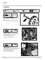
To induct chemical into the tank refer to the following instructions:
Refer to Figure 18
1. Fill the main sprayer tank with the carrier
needed and transport the sprayer to the field
where the sprayer will be used.
2. Make sure the boom section switches are all
off and operate the pump.
3. Turn the agitation valve #1 to “AGITATION”,
the tank valve #2 to “MAIN TANK” and the operation valve #3 to “SPRAY”. Be sure the
valve to the tank is open.
4. Turn the product valve #4 from “OFF” to “INDUCT”.
5. Add chemical to inductor tank.
6. Turn inductor valve #5 from “INDUCTOR
OFF” to “INDUCTOR ON”.
14993
Raven G1 Autoboom (Optional
Equipment)
Figure 18
Product Valve and Inductor Valve
The Raven Autoboom is a system that helps automatically adjust the height of the boom to
changing terrain. Although this option will allow
the sprayer to be driven faster most of the time,
take care to avoid large obstacles and large terraces as the autoboom will only sense terrain
changes at the point of the wheel sensor.
For information on installation, calibration, and
operation of the system, refer to the Raven manuals supplied.
9/1/2009
500-644M
TSF660
36
Tank Fill Using Existing Pump Operations (If
Equipped) (2006-)
The Tank Fill can be used to fill the main sprayer tank using the existing sprayer pump. To do so refer to the
following instructions:
1. Make sure sprayer pump is off and insert supply tank
hose into the main quick-fill coupler. Leave quick-fill
valve off.
Refer to Figure 19
2. Turn agitation valve #1 to “OFF”. Turn tank valve #2 to
“MAIN TANK”.
3. Open supply tank valve making sure that positive
head pressure is maintained at the quick-fill to prevent
back-flow from the sprayer tank.
!
WARNING
Make sure the supply tank is higher than the sprayer tank. Failure to do so can cause back-flow from the sprayer tank causing
sickness, serious injury or death from water contamination.
24494
Figure 19
Control Panel
4. Open quick-fill valve under the main frame.
Refer to Figure 20
5. Turn product valve #4 from “OFF” to “TANK FILL”.
6. Make sure the boom section valve switches are all off,
start the pump and fill the tank.
7. When finished, follow this order:
a. Turn off pump.
b. Rotate product valve #4 from “TANK” to “OFF”.
c. Shut quick fill valve under walkboard.
d. Shut off supply tank valve.
e. Rotate operation valve #3 to “SPRAY”.
NOTE: Make sure there is positive head pressure from
supply tank during this procedure.
14993
Figure 20
Product Valve and Inductor Valve
500-644M
9/1/2009
Adjustments 37
Adjustments
Boom Height
After calibrating your sprayer for the specific nozzle you will use at a desired pressure, and tractor
speed, the main field adjustment is the boom
height. Depending on which type of nozzle you
are using, you need to set your boom height so
that you achieve the correct overlap for that specific nozzle. If the crop canopy is taller in some
fields than others, you will need to adjust the
boom height accordingly. Refer to the nozzle
charts located in this manual to determine the
height of the boom needed. Use the elevator
gauge as a height reference.
EXAMPLE: A 2.5 MeterCone nozzle at 20 inch
spacing is being used. From the nozzle chart {refer to section 4 of this manual or the Application
Guide}, a height of 19 to 21 inches above the top
of the crop is required. If the crop is 6 inches off
the ground, the boom height should be set to 25 to
27 inches off the ground.
Nozzle Pressure
Another area that will need some field adjustments is the nozzle pressure. As your tank level
decreases, you may have to adjust the boom
pressure to keep the pressure at the same magnitude for what the sprayer was calibrated for if
your sprayer is not equipped with a monitor.
Watch your pressure gauge and be aware of
changes in the pressure.
Tank Straps
The tank straps that wrap around the sprayer tank
may become loose after the first few hours of operation. This occurs when the tank settles in the
saddle. Polyethylene tanks are especially susceptible to this. Retighten the tank straps to secure
your tank.
9/1/2009
500-644M
38
TSF660
Manual Pressure Adjustment Valve
Refer to Figure 21
The manual pressure adjustment valve allows the
operator to choke down the amount of fluid flowing to
the boom. When the valve is wide open and the application is at a low rate, a small amount of
adjustment on the butterfly valve makes a large difference in the flow rate. To dampen the sensitivity of
the system, adjust manual pressure adjustment
valve so that the pressure of the system is 20 psi
greater than the maximum flow you want to achieve.
To adjust the manual pressure adjustment valve,
open the butterfly valve until it is completely open.
Operate the pump at the same rpm you would when
spraying, and adjust the manual pressure adjustment valve until the system pressure is reading 20
psi greater than the maximum application pressure.
Butterfly Valve
Manual Pressure
Adjustment Valve
On the Raven Monitor control system, you will have
to adjust the manual pressure adjustment valve with
clean water coming out of the nozzles.Operate the
pump at the same rpm you would when spraying,
and adjust the manual pressure adjustment valve
until the system pressure is reading 20 psi greater
than the maximum application pressure.
22939
A good time to do this would be during calibration of
the sprayer.
!
Figure 21
Manual Pressure Adjustment
CAUTION
If equipped with a boom control valve without a bypass
(Raven Monitor Unit) adjust the boom flow throttle valve
when the sprayer is full of clean water (no chemical added). Never adjust the valve when you would be exposed to
chemical coming out of the boom.
With the manual pressure adjustment valve set correctly, the system pressure will be able to be
adjusted without large fluctuations in the pressure.
NOTE: When the pressure is increased at a later
date, the manual pressure adjustment valve will
need to be opened, and re-calibrated.
500-644M
9/1/2009
Adjustments 39
Agitation Adjustment
Refer to Figure 22
The agitation valve is used to adjust the pressure
to the agitation nozzles in the tank. Refer to the
agitation gauge, and adjust the pressure to a desired rate. Different chemicals require different
agitation pressures to keep the chemical in
suspension.
!
CAUTION
If using liquid fertilizer or any other chemical that will
corrode brass, install a gauge protector under the
brass agitation gauge or plug the gauge hole. Failure
to do so will eventually cause the gauge to fail and
chemical to be expelled from the gauge.
Operating Whirlfilter®
There is one Whirlfilter® on the Great Plains
Sprayer. The Whirlfilter® filters the chemical solution being sprayed.
24495
Figure 22
Control Panel
Refer to Figure 23
Clean-out the solution Whirlfilter®
1. Fill the sprayer tank with water and turn the
pump on.
2. With the pump running, slowly open the
clean-out valve and allow the grit to flow out
into a bucket. Clean out the solution Whirlfilter® only when the sprayer tank is filled with
water and no chemical has been added.
3. Close the clean-out valve and turn off the
pump.
4. Dispose of the grit and water in the same
manner described on the manufacturer’s label of the latest chemical used in the sprayer.
24496
Figure 23
Quick-fill Ball Valve
9/1/2009
500-644M
40
TSF660
Elevator Slide Adjustment
Refer to Figure 24
The polyethylene slides on the elevator can be adjusted to take out any side-to-side play.
Periodically check the slide pads (A) for wear. As
the pads wear, tighten 1/2-inch bolts (B) on both
sides of elevator frame (C) until pads just touch
frame.
Tighten the slides so that there is a minimal
amount of play in the elevator.
Important: When tightening the slides be sure
to keep the elevator slide centered in the elevator mount. If the elevator is adjusted to one
side there can be an interference.
Cycle the elevator a few times to ensure there is
no binding and that the slides are sufficiently
tightened.
17000
Figure 24
Hydraulic Elevator
500-644M
9/1/2009
Troubleshooting 41
Troubleshooting
Problem
Problem Area
Specific Checks
Solutions
Pressure
decreasing
Between gauge
and liquid supply
Pump wearing
Rebuild or replace pump
Plugged suction or pump to pressure head hose
Clean hose and reduce cause of clogging
Plugged Whirlfilter
Clean out Whirlfilter
Plugged gauge
Remove the quick disconnect fitting and
flush gauge protector
Check suction hose & fittings for
air leaks. Air in system is indicated
by buffs of air at nozzles
Remove obstruction from clogged area
Vortex in tank suction
Align agitators properly
Cracked pump housing
Replace pump housing
Nozzle screens clogged
Clean screens
Nozzle orifices plugged
Remove material with soft brush or air
Boom hoses becoming clogged
Remove obstruction from clogged area
Boom hoses pinched
Use cable ties to position hose so it will
not kink
From nozzle charts check liquid
demand against pump capacity
(nozzle requirement + agitation
requirement)
Reduce swath width by nozzle reduction;
install smaller nozzles and drive at a lower
rate of speed
Electric ball valve or gauge not
functional
Replace or repair
Pressure adjust switch faulty
Test switch & replace if faulty
Fuse is out in control box
Replace fuse
Manual pressure adjustment valve
not all the way open
Open the manual pressure valve all the
way and allow the electric ball valve to
govern the pressure
Tank shut-off valves off
Make sure all tank shut-off valves are open
Loose fittings
Tighten fittings so pump can prime
Collapsed suction hose to pump
Replace hose
Pressure
fluctuating
Pressure
increasing
Pressure cannot
increase
No pressure
Between pump
outlet and liquid
Between gauge
and nozzle
Pump or electric
ball valve
Plumbing
Obstruction in suction hose or tank Remove obstruction
No pressure
Pressure cannot
decrease
9/1/2009
Pump
Pump or electric
ball valve
Pump not primed
Turn off valve after Whirlfilter. Turn agitation/flush valve to “flush” or “off”. Turn off
chemical inductor valve. Open valve under
tank sump. Turn main valve to “main tank”.
Open Whirlfilter clean-out valve to prime
pump. When water comes out of valve,
pump is prime.
Hydraulic pump running in the
wrong direction
Switch hydraulic hoses in the tractor outlet
PTO pump coupler loose
Tighten PTO coupler
Tank agitation restricted
Check that the agitator valve is open and
that the liquid is being agitated
500-644M
42
TSF660
Problem
Problem Area
Solutions
Liquid will not induct
Chemical
Inductor
Make sure the valve below the inductor tank is open
Make sure the pump is in operation and has prime
Make sure the venturi bypass valve is open
Inductor overflow
Chemical
Inductor
Close valve below inductor tank until pump is running, has pressure
and venturi valve is open
Boom will not fold
Hydraulic block
assembly
Check electrical connections
Check for leakage at the valve and at the cylinders
Check solenoid valves at the block
Firing Diagram for Fasse 700-0807-4208 Great Plains 833-423C
Switch No.
Boot Color
Switch Position
Left Foam (stat)
Center (off)
Right Foam (stat)
Hot Wires
Red & Wht 4 Cond
--------Red & Grn 4 Cond
Pin Out Location
D-4WP, A-4WP
--------D-4WP, C-4WP
Pressure Ports
Tank Ports
1 Long
White
---------
---------
2 Long
Red
Up (mom)
Center (off)
Down (mom)
Red/Blk & Grn
--------Red/Blk & Grn & Blk/Wht
5-12P, 10-12P
--------5-12P, 10-12P, 9-12P
C5
---------
3 Long
White
Up (mom)
Center (off)
Down (mom)
Org/Blk & Grn
--------Org/Blk & Grn & Blk/Wht
6-12P, 10-12P
--------6-12P, 10-12P, 9-12P
C4
---------
4 Long
Blue
Up (mom)
Center (off)
Down (mom)
Wht/Blk & Grn
--------Wht/Blk & Grn & Blk/Wht
7-12P, 10-12P
--------7-12P, 10-12P, 9-12P
C3
---------
5 Short
Green
Up (mom)
Center (off)
Down (mom)
Grn/Wht & Blu/Wht & Grn
--------Grn/Wht & Blu/Wht & Grn & Blk/Wht
A-3P, B-3P, 10-12P
--------A-3P, B-3P, 10-12P, 9-12P
6 Short
Yellow
Up (mom)
Center (off)
Down (mom)
Grn/Blk & Red/Wht & Grn
12-12P, C-3P, 10-12P
----------------Grn/Blk & Red/Wht & Grn & Blk/Wht 12-12P, C-3P, 10-12P, 9-12P
7 Short
Grey
Up (mom)
Center (off)
Down (mom)
Wht & Blu & Grn
--------Wht & Blu & Grn & Blk/Wht
8 Short
Red
Up (mom)
Center (off)
Down (mom)
---------------------------------
---------------------------------
---------------------------------
Function
Left Foam Marker
Off
Right Foam Marker
--------C5
Left Tilt Up
Off
Left Tilt Down
--------C4
Center Up
Off
Center Down
--------C3
Right Tilt Up
Off
Right Tilt Down
C7
--------C14
C14
--------C7
Left Outer Fold
Off
Left Outer Unfold
C6
--------C13
C13
--------C6
Left Inner Fold
Off
Left Inner Unfold
3-12P, 8-12P, 10-12P
--------3-12P, 8-12P, 10-12P, 9-12P
C2
--------C9
C9
--------C2
Right Inner Fold
Off
Right Inner Unfold
Red & Org & Grn
--------Red & Org & Grn & Blk/Wht
1-12P, 2-12P, 10-12P
--------1-12P, 2-12P, 10-12P, 9-12P
C1
--------C8
C8
--------C1
Right Outer Fold
Off
Right Outer Unfold
Blk (zip)
Blk
Blu/Blk
Blk
--------11-12P
4-12P
B-4WP
---------------------------------
---------------------------------
Ground
Ground
Ground
Ground
29641
500-644M
9/1/2009
Maintenance and Lubrication 43
Maintenance and Lubrication
Proper servicing and adjustment is the key to the long
life of any farm implement. With careful and systematic inspection, you can avoid costly maintenance,
time and repair.
Sprayer/Boom Maintenance
Proper servicing and maintenance is the key to the
long life of all farm equipment. With careful and systematic inspection of your sprayer, you can avoid
costly maintenance, downtime and repair.
1. After several hours of operation, check sprayer
for loose bolts, pins and hose clamps.
2. Check hoses, pumps, valves and fittings for
leaks. Always wear rubber gloves when making
repairs and adjustments.
3. Clean nozzles with an air hose with less than 30
P.S.I. Periodically replace nozzles.
4. Keep elevator slide pads properly adjusted. Lubricating slide pads with grease may cause dirt
accumulation that jams elevator. If necessary,
use silicone spray on slide pads.
last used in the sprayer. Rinse out the tank and spray
the rinse water on the last field that was sprayed.
Flush the sprayer with fresh water and spray the water in the field that was last sprayed. While the sprayer
is being flushed at the field, turn the boom section
switches "on" to flush the nozzles, then turn them "off"
to flush out the throttling valves and bypass lines {if
equipped}. Repeat this procedure several times.
General Information
If equipment is to be used in freezing or near freezing
conditions, protect pump and plumbing system by
thoroughly draining liquid and pumping antifreeze
{Great Plains strongly recommends the use of recreational vehicle antifreeze} solution through the
plumbing system.
Before working on, servicing or making adjustments
on sprayer, always disengage power, shut off tractor
engine, make sure all moving parts have stopped,
and all pressure in the system is relieved.
6. Check for proper air pressure in the sprayer tires.
22 P.S.I. is recommended for the 13.6 x 38 tires.
Check the conditions of hoses and connections frequently. Release the system pressure before
working on the sprayer. To release the pressure flip
the boom section switches on and off without the
pump running. Always wear rubber gloves when
making repairs or adjustments. Make sure all “Personal Safety Equipment” {gloves, goggles, etc.}
listed on Page 5, are stored in an easily accessible
place but protected from potential contamination from
dust or chemicals.
7. Wash sprayer and boom daily using a safe solvent, or soap and water.
Check the sprayer for any loose bolts, pins, and hose
clamps.
8. If equipped with a foam marker, clean the air filter
on the air pump no less than once a week, even
more often in extreme conditions.
Check the hoses, pumps, valves, and fittings for any
leaks.
5. For lubrication points and intervals refer to “Lubrication” on Page 46.
9. Once a season lubricate multiple nozzle bodies
with silicone spray. Remove nozzle and spray
into opening to lubricate nozzle body so it will
turn. DO NOT use petroleum based lubricant as
this will cause the seals to swell and make it impossible to rotate the nozzle body.
Equipment Cleanup
Nozzles should be cleaned with a low pressure {less
than 30 psi} air hose, and periodically replaced. Haul
a supply tank of water so you can clean the spray
tank and applicator out in the field. Never wash tank
out in the yard or at a car wash.
Dispose of leftover chemical in the same manner described on the manufacturer’s label of the chemical
9/1/2009
Inspect all parts of the sprayer for wear and rust. Repair and paint parts as necessary.
Pump Maintenance and Repair
Ace Pumps
The centrifugal pump is designed for long life and service. Through the years, there may be a need to replace the mechanical seal or service some
component of the pump. A mechanical seal may
weep slightly, but if it starts to drip, the pump will have
to be disassembled. Before disassembling the pump,
be sure to wash it out with fresh water.
If the pump is leaking, before removing it from the
sprayer, run the pump with adequate water in the tank
to diagnose the actual pump problem.
500-644M
44
TSF660
Ace Hydraulic Pump Seal Replacement
Refer to Figure 25
Disassembly
1. Remove four 5/16” hex head cap screws from rear of
motor. Remove motor and coupler.
2. Remove rear internal bearing snap ring.
3. Remove four 3/8” x 3/4” hex head cap screws from
mounting frame. Remove volute.
Assembly
1. Install forward internal bearing snap ring in mounting
frame.
2. Press in forward bearing from rear side of mounting
frame to snap ring.
3. Install two external shaft retainer rings with spacer between on shaft.
4. Press shaft assembly through forward bearing until forward shaft snap ring rests against inner face of forward
4. Remove 3/8” lock nut from shaft. Insert flat file into imbearing.
peller vane to hold stationary. CAUTION: Excess
5. Press rear bearing over shaft.
torque may cause damage to plastic impellers.
5. Press shaft out of impeller using one 5/16” hex head 6. Insert rear internal bearing snap ring.
cap screw from step 1. Remove impeller, key, and ro- 7. Slide rubber slinger over shaft and push back to front
tating seal member.
bearing.
6. Press shaft/bearing assembly out of frame.
8. Clean old sealant from mounting frame seal bore.
7. Remove stationary seal member by prying out with
screwdriver or pressing out from motor end of pump
housing.
9. Install o-ring in shaft groove.
8. Remove o-ring from shaft groove.
NOTE: If only replacing the pump seal: 1) Press the
shaft/bearing assembly into frame. 2) Reinstall rear internal bearing snap ring. 3) Skip to Assembly step 8.
9. Press bearings off of shaft.
10. Remove forward internal bearing snap ring.
10. Apply non-hardening Type 2 Permatex or similar under
stationary seal flange.
11. Place stationary portion of seal over shaft and press into
seal bore cavity. Use 1-3/8” ID pipe or PTO adapter to
press seal flange evenly on all sides.
12. Install rotating portion of seal over shaft and o-ring by
hand. The two polished seal faces should face each other. Avoid contacting polished seal faces.
13. Insert key in keyway. Install impeller on shaft.
14. Place lock washer and 3/8” lock
nut on shaft and tighten nut.
15. Replace volute o-ring or gasket,
volute, and four 3/8” x 3/4” cap
screws.
16. Position coupler in pump shaft
slot and fill cavity surrounding
coupler with grease.
17. Install motor by aligning motor
tang and coupler slot. Rotate
motor until nameplate faces up.
18. Install four 5/16” cap screws.
23373
Figure 25
Ace Hydraulic Pump
500-644M
9/1/2009
Maintenance and Lubrication 45
Shear Bolt Replacement
Refer to Figure 26
Your Great Plains sprayer is equipped with shear bolts to
help prevent excessive damage to the booms. These are
located at the inner boom pivot posts at the ends of the
center section. If the shear bolts breaks replace it with a
1/2” x 3” grade 5 bolt (1). Using a different grade bolt will
cause premature failure. It is recommended to replace
these bolts at the start of the spraying season every year
to insure the bolts have not been weakened through use
or rusting.
Storage
1. Empty solution from the tank, clean the chemical inductor {if included}, and store or dispose of the
chemical as recommended by the manufacturer’s
chemical label.
2. Flush the entire sprayer system with clean water.
3. Clean out Whirlfilter®. Refer to “Operating Whirlfilter®“on Page 31.
4. Circulate 3 - 5 gallons of antifreeze {Great Plains
strongly recommends the use of recreational vehicle
antifreeze} through the system including the pump,
hoses and nozzles. Drain the sprayer and properly
dispose of antifreeze. It is advisable to remove the
pump and store it in a warm, dry environment during
the winter.Regular antifreeze is harmful or fatal to
animals and humans. Use carefully according to the
label’s instructions. We strongly recommend the use
of recreational vehicle antifreeze which does not exhibit these harmful side effects.
22940
Figure 26
Shear Bolt Replacement
5. Remove nozzles, disconnect the control box, and
place them indoors with the pump.
6. Change filters in the tractor cab after finished.
7. Wash off the exterior of the sprayer thoroughly using
a safe solvent or soap and water.
8. Inspect all parts of the sprayer for wear and rust. Repair and paint parts as necessary.
9. Store the sprayer in a dry area away from direct sunlight.
9/1/2009
500-644M
46
TSF660
Lubrication
Multipurpose
spray lube
Multipurpose
oil lube
Multipurpose
grease lube
50
Intervals at which
lubrication is required
Seasonally
Two Wheel Bearings
Repack and check the seals every 500 hours of
use.
Type of Lubrication: Wheel bearing grease.
13854
10
Lubrication Point
Swing arm weldment top and bottom, both sides
of the center section, four zerks total
Type of Lubrication: Grease
Quantity = Until resistance is felt
20417
30
Lubrication Point
Top and bottom of inner pivot tube weldment, both
ends of the center section, four zerks total
Type of Lubrication: Grease
Quantity = Until resistance is felt
20418
500-644M
9/1/2009
Maintenance and Lubrication 47
30
Lubrication Point
Base pivot inner fold section weldment, both
booms, two zerks total
Type of Lubrication: Grease
Quantity = Until resistance is felt
20419
30
Lubrication Point
Base pivot outer fold section weldment, both
booms, four zerks total
Type of Lubrication: Grease
Quantity = Until resistance is felt
20420
30
Lubrication Point
Base pivot boom breakaway, both booms, four
zerks total
Type of Lubrication: Grease
Quantity = Until resistance is felt
20420
9/1/2009
500-644M
48
TSF660
30
Lubrication Point
End wing weldment and breakaway boom, both
ends of boom, four zerks total
Type of Lubrication: Grease
Quantity = Until resistance is felt
20421
500-644M
9/1/2009
Options 49
Options
Chemical Inductor
The chemical inductor provides a safe and easy way to
put chemical into the tank, which keeps an operator
from having to climb up on the walkboard and dispense the chemical into the tank from the tank lid.
Placing the chemical into the inductor tank allows it to
transfer the chemical into the sprayer tank.
For additional information refer to:
• “Important Safety Information” on page 1.
• “Operating Instructions” on page 23.
• “Troubleshooting” on page 41.
• “Maintenance and Lubrication” on page 43
To order the option, contact your Great Plains dealer.
Option Packages
Part Number
Chemical Inductor Assembly
502-158A
16142
Foam Marker
The High Volume Foam Marker is specifically for extreme residue conditions. It can be adjusted to produce
a continuous stream of foam.
To order the option, contact your Great Plains dealer.
Option Packages
Part Number
Foam Marker Kit 90 ft.
502-147A
22675
Raven G1 Autoboom
The Raven Autoboom is a system that helps automatically adjust the height of the boom to changing terrain.
To order the option, contact your Great Plains dealer.
Option Packages
Part Number
G1 Autoboom
833-421C
G1 Autoboom with Cylinders (2006-)
510-038A
Open Center Conversion Kit
833-422C
9/1/2009
25024
500-644M
50
TSF660
Pumps
The standard TSF660 does not include a pump. Optional
hydraulic pump is available.
Ace Hydraulic Pump
If ordered with a new TSF660 (Option 35), the pump is
pre-installed prior to delivery.
Description
Option
Part
Numbers
PUMP - TS HIGH VOL HYD
35
507-106A
For operation, see “Hydraulic Driven Pumps” on
page 21.
Figure 27
Hydraulic Pump Components
27301
Figure 28
Ace Flow Limiter
23395
Pump kit weight: 40 lbs (18 kg)
Ace Flow Limiter
On tractors with LOAD SENSING (LS) Closed Center hydraulic systems, this device limits the flow of oil to the Ace
motor and prevents failures due to misapplication. Your
Great Plains dealer can assist with installation of the flow
limiter.
Description
Part
Numbers
FLOW LIMITER VALVE - ACE PUMP
FLOW LIMITER VALVE - ACE PUMP
829-125C (2006-)
829-131C (2007+)
For use, see “Ace Pump Flow Limiter (Option)” on page
17.
500-644M
9/1/2009
Specifications and Capacities 51
Specifications and Capacities
Model
TSF660
Boom Width
60’
Tank Capacity
650 gal.
Nozzle Spacing
Number Of Nozzles
20” or 30”
36 (20” spacing)
25(30” spacing)
Approx. Empty Weight
6,950 lbs.
Approx. Full Weight (Max)
12,400 lbs.
Working Width
Transport Width
63’
108” with wheels in
Transport Height
135” with wheels out
12’
Length
19’ 10”
Wheel/Tire Size
320/85R 38 Radial
Wheel Spacing
60” - 120”
Tire Inflation Chart
Tire Size
Inflation
PSI
13.6 x 38 6 ply Tractor Tread
22
320/85R 38 Radial
52
NOTE: All tires are warranted by the original manufacturer of the tire. Tire warranty information can be found
in the brochures included with your Operator’s and Parts Manuals or online at the manufacturer’s websites.
For service assistance or information, contact your nearest Authorized Farm Tire Retailer.
Manufacturer
Titan
Goodyear
Firestone
9/1/2009
Website
www.titan-intl.com
www.goodyearag.com
www.firestoneag.com
500-644M
52
TSF660
Appendix
Torque Values Chart
Bolt Head Identification
Bolt Head Identification
Bolt Size
(Inches)
Grade 2
Grade 5
in-tpi1
N · m2
ft-lb3
N·m
1/4" - 20
7.4
5.6
1/4" - 28
8.5
6
Grade 8
Bolt Size
(Metric)
5.8
8.8
Class 5.8
10.9
Class 8.8
Class 10.9
ft-lb
N·m
ft-lb
mm x pitch 4
N·m
ft-lb
11
8
16
12
M 5 X 0.8
4
3
6
5
9
7
13
10
18
14
M6X1
7
5
11
8
15
11
N·m
ft-lb
N·m
ft-lb
5/16 - 18
15
11
24
17
33
25
M 8 X 1.25
17
12
26
19
36
27
5/16" - 24
17
13
26
19
37
27
M8X1
18
13
28
21
39
29
3/8" - 16
27
20
42
31
59
44
M10 X 1.5
33
24
52
39
72
53
3/8" - 24
31
22
47
35
67
49
M10 X 0.75
39
29
61
45
85
62
7/16" - 14
43
32
67
49
95
70
M12 X 1.75
58
42
91
67
125
93
7/16" - 20
49
36
75
55
105
78
M12 X 1.5
60
44
95
70
130
97
1/2" - 13
66
49
105
76
145
105
M12 X 1
90
66
105
77
145
105
1/2" - 20
75
55
115
85
165
120
M14 X 2
92
68
145
105
200
150
9/16" - 12
95
70
150
110
210
155
M14 X 1.5
99
73
155
115
215
160
9/16" - 18
105
79
165
120
235
170
M16 X 2
145
105
225
165
315
230
5/8" - 11
130
97
205
150
285
210
M16 X 1.5
155
115
240
180
335
245
5/8" - 18
150
110
230
170
325
240
M18 X 2.5
195
145
310
230
405
300
3/4" - 10
235
170
360
265
510
375
M18 X 1.5
220
165
350
260
485
355
3/4" - 16
260
190
405
295
570
420
M20 X 2.5
280
205
440
325
610
450
7/8" - 9
225
165
585
430
820
605
M20 X 1.5
310
230
650
480
900
665
7/8" - 14
250
185
640
475
905
670
M24 X 3
480
355
760
560
1050
780
1" - 8
340
250
875
645
1230
910
M24 X 2
525
390
830
610
1150
845
1" - 12
370
275
955
705
1350
995
M30 X 3.5
960
705
1510
1120
2100
1550
1-1/8" - 7
480
355
1080
795
1750
1290
M30 X 2
1060
785
1680
1240
2320
1710
1 1/8" - 12
540
395
1210
890
1960
1440
M36 X 3.5
1730
1270
2650
1950
3660
2700
1 1/4" - 7
680
500
1520
1120
2460
1820
M36 X 2
1880
1380
2960
2190
4100
3220
1 1/4" - 12
750
555
1680
1240
2730
2010
1 3/8" - 6
890
655
1990
1470
3230
2380
1 3/8" - 12
1010
745
2270
1670
3680
2710
1 1/2" - 6
1180
870
2640
1950
4290
3160
1 1/2" - 12
1330
980
2970
2190
4820
3560
1
in-tpi = nominal thread diameter in inches-threads per inch
2
N· m = newton-meters
3
4 mm
ft-lb= foot pounds
x pitch = nominal thread diameter in millimeters x thread pitch
Torque tolerance + 0%, -15% of torquing values. Unless otherwise specified use torque values listed above.
500-644M
9/1/2009
Appendix 53
Warranty
Great Plains Manufacturing, Incorporated warrants to the original purchaser that this spraying equipment will be free from defects in material
and workmanship for a period of one year from the date of original purchase when used as intended and under normal service and conditions
for personal use; 90 days for commercial or rental purposes. This Warranty is limited to the replacement of any defective part by Great Plains
Manufacturing, Incorporated and the installation by the dealer of any
such replacement part. Great Plains reserves the right to inspect any
equipment or part which are claimed to have been defective in material
or workmanship.
This Warranty does not apply to any part or product which in Great
Plains’ judgement shall have been misused or damaged by accident or
lack of normal maintenance or care, or which has been repaired or altered in a way which adversely affects its performance or reliability, or
which has been used for a purpose for which the product is not designed. This Warranty shall not apply if the product is towed at a speed
in excess of 20 miles per hour.
Claims under this Warranty must be made to the dealer which originally
sold the product and all warranty adjustments must by made through
such dealer. Great Plains reserves the right to make changes in materials or design of the product at any time without notice.
This Warranty shall not be interpreted to render Great Plains liable for
damages of any kind, direct, consequential, or contingent, to property.
Furthermore, Great Plains shall not be liable for damages resulting from
any cause beyond its reasonable control. This Warranty does not extend to loss of crops, losses caused by harvest delays or any expense
or loss for labor, supplies, rental machinery or for any other reason.
No other warranty of any kind whatsoever, express or implied, is
made with respect to this sale; and all implied warranties of merchantability and fitness for a particular purpose which exceed
the obligations set forth in this written warranty are hereby disclaimed and excluded from this sale.
This Warranty is not valid unless registered with Great Plains Manufacturing, Incorporated within 10 days from the date of original purchase.
9/1/2009
500-644M
Great Plains Manufacturing, Inc.
Corporate Office: P.O. Box 5060
Salina, Kansas 67402-5060 USA