1
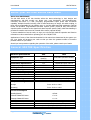
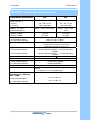
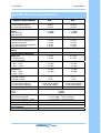
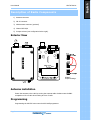
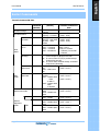
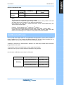
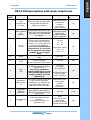
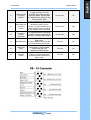
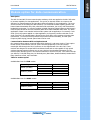
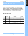
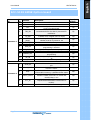
SD170E Series
Safety Information
WARNING
¾
NEVER connect the transceiver to an AC outlet. This may pose a fire hazard or result in an
electric shock.
¾
NEVER operate the radio transmitter without a suitable artificial load or antenna connected
¾ DO NOT allows children to operate transmitter-equipped radio equipment.
CAUTION
¾ DO NOT operates the transceiver near unshielded electrical blasting caps or in an explosive
atmosphere unless it is a type especially designed and qualified for such use.
¾ NEVER modify a transceiver or accessory except as instructed in the service manual,
engineering bulletins or formal communication as this may invalidate any warranty, guarantee
or type approval.
¾ NEVER use the transceiver in an aircraft.
¾ NEVER use the transceiver near to sensitive medical equipment or in areas where instructed
not to do so, e.g. Petrol filling stations.
¾
NEVER mount the transceiver unit on or near the Airbag or Airbag activation device.
¾
NEVER use an accessory not recommended or supplied by Maxon may cause damage to
equipment or injury to personnel, and will invalidate warranty.
¾
DO NOT use or place the transceiver in areas with temperatures below -30°C or above
+60°C, In areas subject to direct sunlight, such as the dashboard.
¾
AVOID placing the transceiver in excessively dusty environments.
¾
DO NOT fit the transceiver in such a manner that the antenna is next to, or touching,
exposed parts of the body, especially the face or eyes, while transmitting.
¾
ALWAYS Install the SD170E using a suitable heat sinking surface.
¾
NEVER operate the radio transmitter without a suitable artificial load or antenna connected.
¾
ALWAYS Secure locking nuts on DB09 connector and always disconnect power supply before
removing D-type connector.
For service or repair always return your radio to an authorised Maxon Dealer or warranty
conditions will be invalid.
Page 2
English
User Manual
SD170E Series
Table of Contents
Safety Information ................................................................................................................2
Table of Contents .................................................................................................................2
About your SD170E Series data radio......................................................................................4
About Your SD170E Radio .............................................................................................4
General SD170E Specification.................................................................................................4
SD170E Transmitter Specification ...........................................................................................5
SD170E Receiver Specification ...............................................................................................6
Unpacking Information ..........................................................................................................7
SD170E Features ..................................................................................................................7
Description of Radio Components ...........................................................................................8
SD-170E Series Operation ......................................................................................................9
Channel dip switch chart...................................................................................................... 11
Serial Command ................................................................................................................. 11
Data Protocol...................................................................................................................... 12
Serial Commands ................................................................................................................ 13
Audible alert tones .............................................................................................................. 14
Modem option for data commmunication .............................................................................. 17
ACC-515E GPS Option board ................................................................................................ 18
ACC-514E FFSK Option board ............................................................................................... 19
ACC-513E GMSK Option board ............................................................................................. 20
User Statement ................................................................................................................... 21
Page 3
English
User Manual
SD170E Series
About your SD170E Series data radio
About Your SD170 Radio
The SD-170E Series of RF Link Modules utilize the latest technology in their designs and
manufacturing. SD-170E models are Phase Lock Loop Synthesizer (PLL)/microprocessor
controlled, and offers 1/ 5 watt (Low/High) programmable output power with 16-channel
capability. Multiple functions including 1200 to 9600 baud rates, AC and/or DC audio coupling, in
these fully programmable RF Link Module units, to use FSK GMSK and FFSK modulation optional
boards are provided. Programmable sub-audio squelch system (CTCSS & DCS) and two-tone
squelch system are added to the signal level detect squelch system (RSSI). GPS Data handling is
provided to interface and control an internal GPS receiver (optional board).
To assure satisfaction from the radio, we urge you to thoroughly read the operation and function
information in this manual before operating your SD-171E/SD-174E.
Applications of some of the functions described in this manual are determined by the system you
use. Your dealer will program your radio so that you have the greatest number of functions
possible relative to your needs.
Should you have questions regarding the operation of the radio, please consult your Dealer.
General SD170E Specification
General specification
Equipment Type
Model Series
Performance Specifications
Frequency Range
RF Output
Channel Spacing
Modulation Type
Intermediate Frequency
Number of Channels
Frequency Source
Operation Rating
Power Supply
Temperature Range
VHF
UHF
Data radio (Wireless
Data radio (Wireless Modem)
Modem)
SD-171E
SD-174E
TIA/EIA-603 /ETS 300TIA/EIA-603 /ETS 300-113
113
146-174MHz
450-490MHz
1-5W
1-5W
12.5KHz, 25KHz Programmable
F3D, F3E
45.1MHz & 455KHz
16
Synthesizer
Intermittent 90 : 5 : 5 (Standby : RX : TX)
Ext. Power Supply (12 VDC Nominal)
Storage
From -40°C to +80°C
Operating
From -30°C to +60°C
Current Consumption
Standby(Muted)
< 65mA
Transmit 5Watts RF Power
< 2.0 A
Transmit 2Watts RF Power
Lock Time :
TX to RX attack time
RX to TX attack time
Dimensions
Weight
< 1.0 A
< 10ms
< 20ms (No Power Saving)
< 20ms
(118mm)W X (63mm)H X (35mm)D
266.5grams
Page 4
English
User Manual
User Manual
SD170E Series
SD170E Transmitter Specification
Transmitter specification
Carrier Power
(Nom. Max. Min.)
Hi Power
Low Power
Sustained Transmission
Time 5 10 30Sec
(Nominal Conditions)
Frequency Error
Nominal condition
Extreme condition
Frequency Deviation
25 KHz Channel Spacing
12.5 KHz Channel Spacing
Audio Frequency Response
Adjacent Channel Power
25 KHz Channel Spacing
12.5 KHz Channel Spacing
Conducted Spurious Emission
Modulation Sensitivity
Hum & Noise :
25 KHz Channel Spacing
12.5 KHz Channel Spacing
Modulation Symmetry
Load Stability
Peak Deviation Range
Adjustment @ 1 KHz, Nom
Dev + 20dB
25 KHz Channel Spacing
12.5 KHz Channel Spacing
Page 5
VHF
UHF
5W < 6W > 4.5W
1W<1.5W>0.8W
5W < 6W > 4.5W
1W<1.5W>0.8W
Power : >90% >85% >80%
Power : >90% >85%
>80%
< 0.5 KHz
±2.5 ppm
< 0.75 KHz
±2.5 ppm
Peak ±5.0, Min. ±3.8KHz
Peak ±2.5, Min. ±1.9KHz
Within +1/-3dB of 6dB octave
@ 300 Hz to 2.55 kHz for 12.5 kHz C.S.
@ 300 Hz to 3.0 kHz for 25 kHz C.S.
< 70 dBc @ Nominal Condition , < 65 dBc @ Extreme
Condition
< 60 dBc @ Nominal Condition , < 55 dBc @ Extreme
Condition
< -36 dBm
< -36 dBm
100mV RMS @ 60% Peak Dev.
> 40 dB (without PSOPH)
> 40 dB (with PSOPH)
< 10% Peak Dev @ 1KHz input for nominal dev. + 20dB
No osc at ≥ 10:1 VSWR all phase angles and suitable
antenna
No destroy at ≥ 20:1 all phase angle
Min. 3.5, Max. 6.0
Min. 1.5, Max. 4.0
User Manual
SD170E Series
SD170E Receiver Specification
Receiver Specification
Sensitivity (@ 12dB SINAD)
25 KHz Channel Spacing
12.5 KHz Channel Spacing
Sensitivity ( 1/100 Error
Rate)
With ACC-513
With ACC-514
Amplitude Characteristic
Adjacent Channel Selectivity
25 KHz Channel Spacing(Nom.)
(Extreme Condition)
12.5 KHz Channel Spacing(Nom.)
(Extreme Condition)
Spurious Rejection(100KHz ~
4GHz)
Image / Half IF Rejection
Intermodulation Response
Rejection
±25 kHz/ 50 kHz
±50 kHz/ 100 kHz
Conducted Spurious Emission
9 KHz - 1 GHz
1 GHz – 4 GHz
RX Spurious Emissions
(Radiated)
9 KHz - 1 GHz
1 GHz – 4 GHz
AF Distortion
Nominal condition
Extreme condition
RX Hum & Noise (only audio)
25 KHz Channel Spacing
12.5 KHz Channel Spacing
Receiver Response Time :
Squelch (factory pre-set)
Open
Close
Squelch Attack Time
RF Level at Threshold
RF Level at Threshold + 20dB
Squelch Decay Time
Antenna Socket Input Match
Temperature Stability for
L.O. Frequency
L.O. Frequency Aging Rate
Page 6
VHF
UHF
< 0.28uV
< 0.30uV
< 0.28uV
< 0.30uV
< -113dBm
< -110dBm
< -113dBm
< -110dBm
> -3dB , < +3dB
> -3dB , < +3dB
>
>
>
>
>
70
60
65
50
70
dB
dB
dB
dB
dB
>
>
>
>
>
70
60
65
50
70
dB
dB
dB
dB
dB
> 70 dB
> 70 dB
> 70 dB
> 70 dB
> 70 dB
> 70 dB
< -57 dBm
< -47 dBm
< -57 dBm
< -47 dBm
< -57 dBm
< -47 dBm
< -57 dBm
< -47 dBm
< 3%
< 10%
< 3%
< 10%
< 40 dB without PSOPH
< 40 dB with PSOPH
< 16 ms
< 40 dB without PSOPH
< 40 dB with PSOPH
< 16 ms
-113dBm
-116dBm
< 20 ms (RSSI), < 40 ms (Analog)
< 10 ms (RSSI), < 30 ms (Analog)
5 ms Min., 20ms Max.
> 10 dB Return Loss
1st < 5 ppm, 2nd < 15 ppm from -30° to + 60° C
±2 ppm/ year
SD170E Series
Unpacking Information
Remove and carefully inspect the contents of your package(s) for the following items:
1. Radio
2. User Manual
* If any items are missing or damaged please contact your Dealer or Maxon
Compatible accessory list (sold
separate)
ACC-513E
9600 baud GMSK modem
ACC-514E
4800 baud FFSK modem
ACC – FSK2
1200 Baud FSK modem
ACC-515E
GPS optional board
ACC-516
PCB Interface - used to separate
digital and RF board for alignment
ACC-916E
Personality programming software
ACC-2016E
Individual USB programming cable
SD170E Features
Synthesized Operation with 16 channel capability
1 / 5 Watt programmable output power
Programmable 12.5 / 25 KHz channel spacing
Channel scan
Busy channel lockout
16 channel
RSSI Level check
TX Time-out timer
Power Save
Marked Idle
TX Delay
Dumb mode
Data transmission and reception through FSK modem (Optional Board)
Data transmission and reception through GMSK modem (Optional Board)
Data transmission and reception through FFSK modem (Optional Board)
Support transmission of global position data using GPS receiver board (Optional Board)
Page 7
English
User Manual
SD170E Series
Description of Radio Components
1) Antenna connector
2) DB-15 connector
3) GPS Antenna connector (optional)
4) Channel DIP-S/W
5) Jumper selector (see configuration below right).
Exterior View
CON407
Jumper Settings.
Antenna installation
Fasten the antenna to the radio by turning the antenna cable clockwise onto the BNC
receptacle on left of radio when looking at front of radio.
Programming
Programming the SD170E series uses the ACC-916E programmer.
Page 8
English
User Manual
SD170E Series
SD-170E Series Operation
Channel select / SCAN
Your radio’s channel can be selected by inner DIP-S/W or serial command inputted from external
control system. To change channel by inner DIP-S/W (4), you should open the upper cover and
then look for the DIP-S/W (4) on the digital board of the bottom cover. Once located change the
DIP-S/W to select wanted channel according to channel dip switch chart (see channel chart on
page 11).
To use a serial command for channel selection, it should be inputted by external equipment or
device (ex. Personal computer or PLC) through Pin 8 of DB-15 connector. See the message
format for serial command for full details.
If your radio has been programmed the channel scan, you must enter the scan mode by serial
command.
Transmit
The transmission will be made by various inputs such as PTT signal (Pin 3 of DB-15 connector),
TX serial command and Serial data input (Pin 10 of DB-15 connector: This input is only available
when a modem option board is installed). TTL level is used as PTT signal and is active low. If
you installed an option modem board, you can use RS-232 level as a PTT signal instead of TTL
level. To maintain transmission, continuous PTT signal input is required. If you use TX serial
command for transmission, normally, it’s released by Rx serial command. If RF activity is present;
it will not be illuminated if the radio indicates a “clear” channel. When the channel is “clear”, input
the PTT signal or TX serial command and transmit data or audio. Remove the PTT signal or input
Rx serial command when you have finished transmission.
CAUTION: Operation of the transmitter without a proper antenna installed may result in
permanent damage to the radio.
Receive
When you have finished transmission, remove the PTT signal or input Rx serial command. You
will receive data from another radio or hear another person talking from the connected external
speaker.
Page 9
English
User Manual
SD170E Series
Scan modes
Scanning is a dealer programmable feature that allows you to monitor a number of channels.
Your dealer will help you define a scanning mode and your channel “scan list”
Channel scan
Once the scan list has been established, initiate scan by serial commands. If a conversation is
detected on any of the channels in the scan list, the radio will stop on that channel and you will
be able to hear the conversation. At that time, busy channel data is sent to external equipment or
device through serial command. So, you can identify busy channel data as decoding of received
serial command from your radio in the external equipment or device.
Normally, if you try to transmit during scanning, the transmission will be made on the channel
that the call was received during the programmable scan delay time. The scan delay time is the
amount of time the radio will stay on that channel once activity has ceased. Dealer programming
of 4 ~ 7 seconds is typical). The radio will resume scanning once the scan delay time has expired,
and will continue to scan until the serial command for scan stop is inputted by external
equipment. After the scan resumes, if a transmission is made, the radio will transmit on the
selected priority channel. This feature is similar to priority scan TX except for selection of priority
channel. You can assign a priority channel by inner dip switch only.
Scan channel delete
To temporarily delete a channel from the scan list, simply input the serial command for scan
deletion to the radio while scanning and stopped on the channel to be deleted. This will
temporarily remove that channel from the scan list until the scan is closed or the radio’s power is
reset.
CTCSS / DCS Scanning
To help to block out unwanted calls to your radio, the SD-170E series can be programmed by
your dealer to scan for tones.
Page 10
English
User Manual
SD170E Series
Channel dip switch chart
Serial Command
Serial RX/TX Data Format
(1)
(2)
(3)
(4)
(5)
Asynchronous Serial Data Transfer
Baud Rate : 4,800 bit/sec
Data Bit : 8bit , Non Parity
Stop Bit : 1bit
MSB first transmission
Each serial command is consist of 3 bytes.
1st byte is command and 2nd is data required by command and 3rd is check sum to decide validity
of total contents.
Byte0
ST
1st Byte (Command)
SP
Byte1
ST
2nd Byte (Data)
SP
Byte2
ST
3rd Byte (Check Sum)
SP
Page 11
English
User Manual
SD170E Series
Data Protocol
Protocol for input Serial command
Protocol of data transmission from external equipment or device (: PC) to radio:
External equipment or device
Radio
Input serial command
Response
Receive response
Protocol for output data
Protocol of data transmission from radio to external equipment or device (: PC)
External equipment or device
Radio
Output Data
Receive Data
(with command)
Output Data
Receive Data
Page 12
(with command)
English
User Manual
SD170E Series
Serial Commands
Transmit Command & data
Mode
Channel Change
RTX Mode Send.
Transmit
Command
(BYTE0)
0x64
0x61
From PC
To Radio
0x62
From Radio
To Pc
0x66
Error
Message
0x65
Control of
GPS Power
0x6a
Control of
GPS Data
0x63
Scan
Mode
GPS
mode
0x75
Modem test mode
GMSK
Modem
alignment
mode
Page 13
0x7a
0x7c
FFSK
0x7e
Transmit data
(BYTE1)
0x?? :Current
channel
R(0x72) : Rx mode
T(0x74) : TX mode
F(0x46) : Scan Stop
S(0x73) : Scan Start
O(0x4F) : Scan
Delete
0x00 : 1 Channel
0x01 : 2 Channel
0x02 : 3 Channel
0x0f : 16 Channel
Check sum (BYTE2)
Transmit Command +
data
( 0x64 + Channel )
(
(
(
(
(
0x61+0x72 )
0x61+ 0x74 )
0x62+ 0x46 )
0x62+ 0x73 )
0x62+ 0x4F )
0x66 + 0x00
0x66 + 0x01
*Only for Unmute
Channel, Correct Call
Channel
z It occurs when Scan Delete command
comes except for Busy/Correct Call
z It occurs when PTT key is pushed except
for Busy/Correct Call.
z It occurrs when channel change command
exists during Scanning.
0x00 : GPS Power
( 0x6a + 0x00 )
Off
( 0x6a + 0x01 )
0x01 : GPS Power
On
0x00 : GPS Data
( 0x63 + 0x00 )
Disable
( 0x63 + 0x01 )
0x01 : Release GPS
Data
( 0x63 + 0x02 )
to DB-15
0x02 : Release GPS
Data
to Modem
0x78 : Enable test
( 0x75 + 0x78 )
data
( 0x75 + 0x79 )
0x79 : Disable test
data
0x00 : Disable
( 0x7a + 0x00 )
0x01 : Enable
( 0x7a + 0x01 )
0x00 : Disable
( 0x7c + 0x00 )
0x01 : Enable Mark
( 0x7c + 0x01 )
data
0x00 : Disable
( 0x7e + 0x00 )
0x01 : Enable Space ( 0x7e + 0x01 )
data
English
User Manual
SD170E Series
Receive Command & data
Mode
Process
Complete
Commands
Transmit
Command
(BYTE0)
0xaa
0x55
Transmit data
( BYTE1 )
Check sum( BYTE2 )
: Transmit Command
+ data
ACK
NACK
Note)
This command is return signal for receiving command.
If Byte2 and sum of Byte0 and Byte1 among received data are same, Radio would send
ACK data and execute command. If not, Radio sends Nack data.
User would go into next step if receives ACK data. If user receives Nack data, user
should send command again.
Example: If user changes from 1st Channel to 2nd Channel,
User should send Channel Change Command (0x64, 0x02, (0x64 + 0x2)) to Radio.
If Byte2 and sum of Byte0 and Byte1 among received data are same, Radio sends ACK
data to user and changes to 2nd channel. If not, Radio would send Nack data.
Audible alert tones
Your SD-170E series data radio has a sophisticated microprocessor control which provides a
range of audible tone. If you connect the Speaker filtered OUT (Pin 9 of DB-15 connector) to an
external speaker, you can hear audible tones at the following conditions:
• Attempt to transmit on a channel that is already in use when busy channel lockout has been
programmed into the radio
• Transmission time has exceeded time-out timer programmed length
• When the other group or people finished transmission using repeater
See the status audible alert tones chart for full details.
Status
Warning
Page 14
Description
Audible tone
Busy Channel lockout
Single Beep Tone
Before 5S T-O-T
Single Beep Tone
Transmit Hang on time
Single Beep Tone
English
User Manual
SD170E Series
DB 15 PIN descriptions with input/output level
D-Type
Pin No.
Function
Description
1
Data
modulation IN
(TX Mod)
Signal is directly injected to MOD
through data low pass filter
without pre-emphasis.
2
Data unfiltered
OUT
(RX disc)
Discriminator audio from the SD170E. This is the unprocessed AF
signal prior to tone filtering and
de-emphasis.
3
PTT In
(TX Key)
4
Power
5
Serial Data Out
(TXD)
Busy
(CD)
6
Signal from the ‘external device’
to key the SD-170E transmitter.
This line has an internal pull up
resistor to +5V. Pulling the line to
0V turns on the transmitter.
Note: If you installed option
modem board, you can select
RS-232 signal level by Jumper
(CON407, r) on the digital
board.
Power connection to Out of the
radio.
Serial data output for radio
control or program.
It uses asynchronous data format.
Logic level output from SD-170E
to indicate whether a carrier is
present or not
Note: If you installed an
option modem board, you can
select RS-232 signal level by
Jumper (CON407, r) on the
digital board.
Signal Type
Analog signal
1KHz audio at 60%
peak system
deviation
input level =
100 to 120mVrms
Analog signal
1KHz audio at 60%
peak system
deviation produces
200 to 300mVrms
Input/Outp
ut
I/P
O/P
TTL level
0V = TX
o/c = RX
RS-232 level (option)
+12V = TX
-12V = RX
I/P
DC +12V
TTL level
TTL level
0V = carrier
5V = no carrier
O/P
O/P
RS-232 level (option)
+12V = carrier
-12V = no carrier
Audio
1KHz audio at 60%
peak system
deviation
input level =
6 to 8mV rms
I/P
7
Microphone
filtered audio
IN
This signal is injected to the MOD
at the point through audioamplification, pre-emphasis and
high pass filtering where subaudio tone is mixed with audio.
8
Serial data
IN/OUT
(RXD/TXD)
Serial command or data input and
data output for radio control or
program. It uses asynchronous
data format.
TTL level
I/O/P
Speaker filtered
OUT
Audio output from the audio
amplifier.
It’s filtered by tone-filter, deemphasis circuit.
Audio
1KHz audio at 60%
peak system
deviation produces
Nominal 1Vrms @ 8Ω
O/P
9
Page 15
English
User Manual
10
Serial data IN
for option
modem
11
Serial data Out
for option
modem
12
Serial data busy
for option
modem
(reserved)
13
GPS data input
14
DGPS data
input
15
GPS data
output
Page 16
SD170E Series
The Serial data to be transmitted
is input to this pin. It’s only
available when option modem
board is installed. Inputted data
are modulated by modem IC and
then injected to MOD.
It uses asynchronous data format.
The recovered asynchronous
serial data output from the
receiver. It’s only available when
option modem board is installed.
It uses asynchronous data format.
To eliminate data loss according
to buffer overrun of slave MCU’s
memory, it indicates buffer status.
Data input for initial setting of
GPS module.
It follows NMEA 0183 format and
uses asynchronous data format.
Data input for DGPS Correction of
GPS module. It follows NMEA
0183 format and uses
asynchronous data format.
Position data output from the GPS
module. It follows NMEA 0183
format and uses asynchronous
data format.
RS-232 level
I/P
RS-232 level
O/P
RS-232 level
O/P
TTL level
I/P
TTL level
I/P
TTL level
O/P
English
User Manual
SD170E Series
Modem option for data commmunication
Description
The ACC-513 and ACC-514 are internal option-modems, which are applied to the SD-170E series
to increase capability for data applications. The goal of an internal modem is to improve the
efficiency for data transmission and provide maximum flexibility for user applications. The most
obvious method of increasing the data efficiency is to maximize the data signaling speed in the
limited channel bandwidth. But, FSK, called direct FM modulation, has a very wide transmission
bandwidth requirement. To solve this problem a GMSK (Gaussian Filtered Minimum Shift Keying)
internal option-board can be used. Generally data has a wider bandwidth than audio. So, direct
application of data is not matched with an audio system and its application. For instance, if subaudio (Tone) SQ system applied to a data application, its frequency conflicts with that of subaudio. Moreover, the inputted data is filtered by the audio filter circuit resulting in broken data
transmission. To overcome these problems and provide maximum flexibility, an FFSK (Fast
Frequency Shift Keying) internal option-board can be used.
Communication between DTE and Option-Board
Our internal modem options consist of Slave MCU, Modem IC, and extra circuitry. These optionboards directly communicate with DTE (Data Terminal Equipment) to send and receive
meaningful data through the DB-15 connector on the digital board of the SD-170E. These
modems are designed to accept RS232 serial data format and are also capable of high speed
wireless data-transmission between two or more devices. More detailed information for the
modem option boards is given in the technical manual for the ACC-513/514. Your dealer will help
you define a TX On/Off delay time, RX On delay time, Baud Rate, Modem Enabled, Modem Baud
Rate, Data flow control, and Test Mode.
Table for modem speed
Available Baud rate for FFSK modem
Channel Space
Narrow (12.5KHz)
Standard (25KHz)
DTE Baud Rate
1200
2400
1200
2400
4800
Modem Baud Rate
1200
2400
1200
2400
4800
DTE Baud Rate
4800
4800
9600
Modem Baud Rate
4800
4800
9600
Available Baud rate for GMSK modem
Channel Space
Narrow (12.5KHz)
Standard (25KHz)
Page 17
English
User Manual
SD170E Series
ACC-515E GPS Option board
Transmission GPS Data through Modem
The SD-170E supports GPS data handling. That may help your implementation for a system
related to GPS. If it is not enough for your application, received position data from the GPS
module placed in an SD-170E can be reprocessed by your own application. The ACC-515E is a
GPS module for the SD-170E, which releases 11 different output data according to the NMEA0183 format, which can be selected by you, the available data should be processed by your
application. Received data from the ACC-515E will be released via the DB-15 connector of the SD170E and/or transmitted to another system through an installed modem. More detailed
information for the GPS option board is given in the technical manual for the ACC-515E.
GPS Option board pin-outs
Pin
No.
Function
Description
Input/
Output
1
VCC
6V to 12V Power Input
I/P
2
VBAT
Backup Power Input (3.3V)
I/P
3
ENABLE
GPS Data Out Enable
I/P
4
PSAVE
GPS Power Enable (& Power save input for GPS)
I/P
5
GND
Ground
6
GPS_OUT
Position Data Output
O/P
7
DGPS_IN
DGPS Correction Data Input
I/P
8
GPS_IN
Initial Setting Data Input
I/P
9
+5V
5V Power Input
I/P
Page 18
English
User Manual
SD170E Series
ACC-514E FFSK Option board
Connector
No.
Pin
Function
No.
1
VCC
2
GND
3
PTT
4
TXD_EN
5
TX_END
7
8
MUTE
(Busy)
MODEM_EN
POWER_SAVE
9
CMD_EN
10
11
CMD_IN/OUT
CMD_CLK
12
MODEM_SEL
13
RX_IN
14
TX_OUT
1
Serial_IN
2
Serial_OUT
3
Busy
4
Carrier_Detect
5
PTT_IN
6
PROGRAM
6
Connector 1
Connector 2
Page 19
Description
6V to 12V Power Input
Ground
Signal from the digital board to transmit data key
the SD-170 transmitter
It ensures that the radio has stabilized in
transmission before the data is processed for
modulation.
To finish transmission, it indicates memory buffer
of Master MCU of digital board is empty.
Logic level input from digital board to indicate
whether a carrier is present or not
Modem Enable input
Power save input for modem board.
It indicates that command for Modem
programming is effective.
Data Input and Output for Modem programming.
Clock Input for Modem programming.
It Indicates modem type to Master MCU for
programming.
The FFSK/MSK signal input for the receiver of
modem IC.
The FFSK/MSK signal output when the transmitter
is enabled.
The Serial data to be transmitted is input to this
pin.
The recovered asynchronous serial data output
from the receiver.
To eliminate data loss according to buffer overrun
of slave MCU’s memory, it indicates buffer status.
Handshake signal for RTS control mode. It
indicates whether Slave MCU of modem has
decoded data or not.
Handshake signal for RTS control mode. It
requests data transmission to Slave MCU of
modem.
It’s reserved input for firmware upgrade.
Input/
Output
I/P
I/P
I/P
O/P
I/P
I/P
I/P
I/P
I/P, O/P
I/P
O/P
I/P
O/P
I/P
O/P
O/P
O/P
I/P
I/P
English
User Manual
SD170E Series
ACC-513E GMSK Option board
Connector
No.
Pin
Function
No.
1
VCC
2
GND
3
PTT
4
TXD_EN
5
TX_END
7
8
MUTE
(Busy)
MODEM_EN
POWER_SAVE
9
CMD_EN
10
11
CMD_IN/OUT
CMD_CLK
12
MODEM_SEL
13
RX_IN
14
TX_OUT
1
Serial_IN
2
Serial_OUT
3
Busy
4
Carrier_Detect
5
PTT_IN
6
PROGRAM
6
Connector 1
Connector 2
Page 20
Description
6V to 12V Power Input
Ground
Signal from the digital board to enable transmitter
circuit of modem board.
It ensures that the radio has stabilized in
transmission before the data is processed for
modulation.
To finish transmission, it indicates memory buffer
of Master MCU of digital board is empty.
Logic level input from digital board to indicate
whether a carrier is present or not
Modem Enable input
Power save input for modem board.
It indicates that command for Modem
programming is effective.
Data Input and Output for Modem programming.
Clock Input for Modem programming.
It Indicates modem type to Master MCU for
programming.
The GMSK signal input for the receiver of modem
IC.
The GMSK filtered TX output signal.
The Serial data to be transmitted is input to this
pin.
The recovered asynchronous serial data output
from the receiver.
To eliminate data loss according to buffer overrun
of slave MCU’s memory, it indicates buffer status.
Handshake signal for RTS control mode. It
indicates whether Slave MCU of modem has
decoded data or not.
Handshake signal for RTS control mode. It
requests data transmission to Slave MCU of
modem.
It’s reserved input for firmware upgrade.
Input/
Output
I/P
I/P
I/P
O/P
I/P
I/P
I/P
I/P
I/P, O/P
I/P
O/P
I/P
O/P
I/P
O/P
O/P
O/P
I/P
I/P
English
User Manual
SD170E Series
User Statement
SD170E Series
This product is marked with
Declaration of Comformity
In accordance with the Class II product requirement specified in the R&TTE Directive 1999/5/EC.
This equipment is intended for use in:Austria, Belgium, Bulgaria, Cyprus, Czech Republic, Denmark, Estonia, Finland, France, Germany,
Greece, Hungary, Iceland, Ireland, Italy, Latvia, Liechtenstein, Lithuania, Luxembourg, Malta,
Netherlands, Norway, Poland, Portugal, Romania, Slovakia, Slovenia, Spain, Sweden, Switzerland
& United Kingdom
and requires authorisation (individual licence) for use.
We hereby declare that the above named product is in conformity to all the essential
requirements of Directive 1999/5/EC.
Con la presente si dichiara che il prodotto sopra menzionato è conforme ai requisiti essenziali
della Direttiva 1999/5/CE.
Declaramos que el producto mencionado más arriba cumple todos los requisitos esenciales de la
Directiva 1999/5/CE.
Wir möchten hiermit bekanntgeben, daß das oben genannte Produkt in Übereinstimmung mit
allen erforderlichen Bedürfnissen der 1999/5/EC Direktive seht
Nous déclarons que le produit référencé ci-dessus satisfait aux exigences
R&TTE 1999/5/EC qui lui sont applicables.
If you wish to see the whole Declaration of Conformity, please email
[email protected]
Page 21
English
User Manual
User Manual
SD170E Series
Maxon House,
Cleveland Road,
Hemel Hempstead,
Hertfordshire,
United Kingdom,
HP2 7EY
Tel: + 44 (0) 1442 267 777
Fax: + 44 (0) 1442 215 515
[email protected]
www.maxoncic.co.uk
Page 1