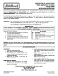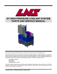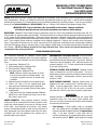
1
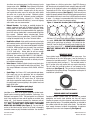
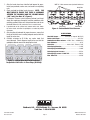
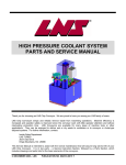
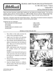
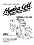
EDELBROCK E-STREET CYLINDER HEADS
For Small-Block Chevrolet V8 Engines
Part #5073 & 5089
INSTALLATION INSTRUCTIONS
®
PLEASE study these instructions carefully before beginning this installation. Most installations can be accomplished with common
tools and procedures. However, you should be familiar with and comfortable working on your vehicle. If you do not feel comfortable
performing this installation, it is recommended to have the installation completed by a qualified mechanic. If you have any questions,
please call our Technical Hotline at: 1-800-416-8628, 7:00 am - 5:00 pm, Pacific Standard Time, Monday through Friday.
IMPORTANT NOTE: Proper installation is the responsibility of the installer. Improper installation
will void your warranty and may result in poor performance and engine or vehicle damage.
DESCRIPTION: Edelbrock E-Street Cylinder Heads are designed for street use, and are interchangeable with 1986 & earlier 302, 327,
350, and 400 c.i.d. Chevrolet engines (not centerbolt). These heads do not have an exhaust crossover passage and therefore do not have
an E.O. number for EGR equipped applications. Check local laws for requirements. Edelbrock cylinder heads have been designed for
maximum flow velocity when matched with Edelbrock intake manifolds, camshafts, carburetors, or additional recommended performance
parts. These complete cylinder heads are assembled with the following components: Stainless steel, one-piece intake and exhaust
valves; 2-ring positive-oil-control seals; 3/8” rocker arm studs and 5/16” guide plates; hardened steel valve spring locators; Edelbrock
Sure-Seat Valve Springs, retainers, and valve keepers. These complete cylinder heads are assembled and prepared for installation right
out of the box. P/N 5073 & 5089 are designed for Flat Tappet Camshafts Only. Please consult your camshaft manufacturer for
recommended valve spring specifications.
BEFORE BEGINNING INSTALLATION
For a successful installation, the Edelbrock E-Street Cylinder
Heads require some components other than original equipment
parts. To complete your installation, you will need the following
items:
q
q
q
q
q
q
q
q
Head gaskets; Edelbrock #7310
Intake manifold gaskets; Edelbrock #7201
Exhaust gaskets; Edelbrock #7204
Valve Cover gaskets; Edelbrock #7549
NOTE: Edelbrock Cylinder Head Gasket Set #7361
may also be used in place of individual gaskets. This
set contains all gaskets necessary for cylinder head
installation.
Edelbrock head bolt kit #8550 (see instructions below)
14mm x 3/4” reach x 5/8” hex, gasketed spark plugs
(heat range to be determined by specific application)
Adjustable rocker arm assembly (Premium roller rockers
recommended)
+.100” longer-than-stock hardened pushrods; Edelbrock
#9629 (For use with stamped steel rocker arms or with
64cc heads in some cases)
PISTON-TO-CYLINDER HEAD CLEARANCE: Edelbrock cylinder
heads are designed for use with flat-top pistons. The use of
domed pistons requires that piston-to-head clearance be checked
before installation. Recommended minimum piston-to-head
clearance is .050”.
VALVE-TO-BORE CLEARANCE: Edelbrock cylinder heads are
designed to be used on engines with a minimum bore size of
4.000”. If used on engines with a bore size less than 4.000”
(307, 305, 283, 267, 265, & 262 c.i.d.), do not use a camshaft
with more than .450” lift or the valves may hit the cylinder bores.
ACCESSORIES
ROCKER GEOMETRY: Rocker geometry should be checked,
making sure that the contact point of the roller (or pad on a stock
rocker arm) remains properly on the valve tip and does not roll
off the edge. Visual inspection of the rockers, valve springs,
retainers, and pushrods should be made to ensure that none of
these components come into improper contact with each other.
If problems with valve train geometry occur, changes such as
pushrod length may be required.
Part #5073 & 5089
Rev. 8/5/15 QT
CHECKING VALVE-TO-PISTON CLEARANCE: Prior to installation,
it is highly recommended that valve-to-piston clearances are
checked and corrected to minimum specs, if necessary. Minimum
intake valve clearance should be .100”. Minimum exhaust valve
clearance should be .110”. E-Street cylinder heads are designed
for use with flat-top pistons.
Although Edelbrock E-Street cylinder heads will accept OEM
components (rocker arms, valve covers, intake manifold, head
bolts, etc.), we highly recommend that premium quality hardware
be used with your new heads.
• Valve Springs: E-Street cylinder heads are assembled
with valve springs that are compatible with both Edelbrock
Performer and stock flat tappet camshafts (See Specifications
table). If any other camshaft is used, check with the
camshaft manufacturer for recommended spring pressures
and maximum valve lift. NOTE: If valve springs are changed
Page 1
©2015 Edelbrock LLC
Brochure #63-5073
to achieve more spring pressures it will be necessary to also
change rocker studs. CAUTION: Some Chevrolet V8 cylinder
heads are factory equipped with “self-aligning” rocker arms.
These rocker arms have a stamped recess on the valve tip
end to guide the rocker arm on the valve stem which allows
the rocker arm to guide the pushrod. Edelbrock cylinder
heads are equipped with hardened pushrod guideplates.
Therefore, non-self-aligning, stamped (i.e., Sealed Power
#R-865R, Pioneer-Barnes #818001 etc.), or non-self-aligning
roller rocker arms are recommended.
lacquer thinner on a lint-free rag to clean. Apply RTV silicone or
ARP thread sealer to head bolt threads, and apply engine oil or ARP
lubricant to the head bolt washers and underside of bolt heads.
Torque bolts to 65 ft./lbs. in three steps (40-55-65), following the
factory tightening sequence (See Figure 3). Check to make sure
engine has proper grounds to chassis. When pouring coolant back
in the radiator make sure to use at least a 50/50 mixture of coolant
to water. A re-torque is recommended after initial start-up and
cool-down (allow 2-3 hours for adequate cooling).
Figure 1 - Steam Hole Locations (400 C.I.D. Engines ONLY)
• Exhaust Headers: Any header or manifold designed for
original equipment heads will fit Edelbrock Cylinder Heads.
Exhaust ports are CNC profiled to match Edelbrock #7204
exhaust gaskets which are recommended for this application.
Use of anti-seize on header bolts is recommended to facilitate
later removal. Edelbrock makes emissions-legal Tubular
Exhaust Systems for many applications. Check the Edelbrock
catalog for complete listing, or call our Technical Hotline.
• Head Bolts or Studs: High quality head studs or head bolts
with hardened washers must be used to prevent galling of the
aluminum bolt bosses. We recommend Edelbrock Head Bolt
Kit #8550. OEM head bolts may be used if they meet these
specs for length: 1-3/4” (short bolts); 3” (medium bolts);
3-13/16” (long bolts). Shorter bolts do not have enough
thread engagement for use with hardened washers. With
OEM bolts, use hardened GM #10051155, ARP #200-8511,
or equivalent washers. Bolt threads, underside of bolt heads,
and washers should be lubricated with an oil/moly mix prior
to installation and torquing.
• Valve Covers: Edelbrock cylinder heads accept stock valve
covers for the year and model for which they are listed. They
also accept Edelbrock valve covers #4449, #4649, #4249 or
#4248.
• Spark Plugs: Use 14mm x 3/4” reach gasketed spark plugs.
Heat range may vary by application, but we recommend
Champion RC-12YC (or equivalent) for most applications.
Champion RC-12YC are 1/4” shorter than “N” series plugs
and may be required for header clearance. Use anti-seize on
the plug threads to prevent galling in the cylinder head, and
torque to 10 ft./lbs.
NOTE: Do not overtighten spark plugs!
Drill three .125” holes in each head using 400 c.i.d. head gasket
as a guide. DRILL ONLY THE THREE LOWER STEAM HOLES
(closest to the spark plugs) as indicated. Drill straight into the
head (90° from the deck) until the drill breaks through into the
water jacket (about 9/16”). COOLANT HOLES ABSOLUTELY
MUST NOT OVERLAP INTO THE HEAD GASKET SEALING
RING AREA!
IMPORTANT NOTICE
These cylinder heads are equipped with valve spring cups. Due
to the diameter of the valve spring cups, it may be necessary to
clearance the head bolt washer #1. The #1 head bolt is called out
in your instruction sheet (see figure 1). The head bolt washer in
the #1 location is the only washer that may require clearancing.
This will allow the head bolt washers to seat properly to the
cylinder head (See Figure 2). This can also be accomplished by
removing the valve spring and cup. Then position washer prior to
installation of cylinder head.
Figure 2 - #1 Head Bolt Washer
INSTALLATION PROCEDURE
Installation is the same as for original equipment cylinder heads.
Consult service manual for specific procedures, if necessary. Use
Edelbrock head gasket #7310. This head gasket has a flattened
steel O-ring around each bore and will provide an excellent, long
lasting seal. It will however compress the aluminum and you
must use #7310 for subsequent gasket changes to get a good
seal. NOTE: YOU MUST DRILL “STEAM HOLES” IN CYLINDER
HEADS FOR 400 ENGINES (See Figure 1). Be sure that the
surface of the block and the surface of the head is thoroughly
cleaned to remove any oily film before installation. Use alcohol or
Part #5073 & 5089
Rev. 8/5/15 QT
PUSHROD GUIDE PLATE ALIGNMENT
Complete Edelbrock cylinder heads are sold with the pushrod
guideplates and rocker studs installed, but they will require
checking for proper valve train alignment and pushrod clearance
before operating engine. The pushrod guideplates are attached to
the cylinder heads with two (each) rocker studs. The stud holes
have enough clearance to adjust the guideplates for optimum
alignment of your valve train components (See Figure 4).
Page 2
©2015 Edelbrock LLC
Brochure #63-5073
1. After the heads have been installed and torqued to specs,
install your pushrods, rocker arms, and rocker arm adjusting
nuts.
2. Check pushrod-to-cylinder head clearance. NOTE: YOU
MUST CHECK TO ENSURE THAT THERE IS CLEARANCE
BETWEEN THE PUSHRODS AND THE CYLINDER HEADS
(.005” min.) (See Note “A”, Figure 4).
3. If adequate clearance exists between pushrod and head,
slowly turn engine over through at least two revolutions while
watching pushrod. Make sure that pushrod does not rub on
the head either at full lift or when the valve is seated closed.
NOTE "A": Most common areas of pushrod interference
Guide Plate
4. If pushrod rubs on the cylinder head, remove rocker arms, loosen
the rocker studs and move the guideplate as needed to provide
clearance.
5. After checking all pushrods for proper clearance, ensure that
the tip of the rocker arm is making adequate contact with the
top of the valve stem.
6. Carefully re-torque to 45 ft./lbs. any rocker studs that
were loosened. Check alignment again to be sure that the
guideplates did not move while torquing the studs.
Valve Stems
Rocker Studs
Figure 4 - Pushrod Guide Plate Clearance
SPECIFICATIONS
Head bolt torque:..................... 65 ft./lbs. (in steps of 40-55-65)
Rocker stud torque:....................................................45 ft./lbs.
Combustion chamber volume:.....#5073: 70cc......#5089: 64cc
Deck thickness:.................................................................9/16”
Valve Size:.................................... Intake- 2.02”, Exhaust- 1.60”
Valve Spring Diameter:...................................................1.460”
Valve Spring Installed Height:........................................1.800”
Valve Spring Seat Pressure:......................................... 125 lbs.
Valve Spring Pressure @ .500” Lift:........................... 320 lbs.
Max. Valve Lift:................................................................0.550”
Figure 3 - Cylinder Head Bolt Torque Sequence
Torque Bolts to 65 ft./lbs. in Three Steps (40-55-65)
®
Edelbrock, LLC • 2700 California St. • Torrance, CA 90503
Tech-Line: 1-800-416-8628
Part #5073 & 5089
Rev. 8/5/15 QT
Page 3
©2015 Edelbrock LLC
Brochure #63-5073