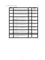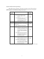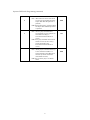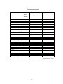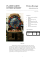
1
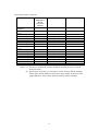
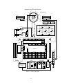
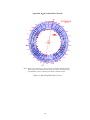
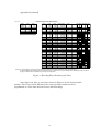
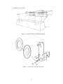
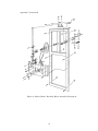
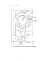
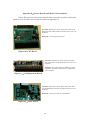
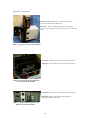
PLANET EARTH ENTERTAINMENT Pirates Revenge OPERATION MANUAL _____________________________________________________________ _ 18 August 1997 Features: • • • • • Bright attention grabbing graphics Hot looking neon ring lighting Exciting Super Fast Skill Stop and Double-down play features Oversized high reliability buttons Operator programmable Specifications: Parameter Voltage Frequency Weight Value 115 60 200 Overview Pirates Revenge consists of a lighted clock face with motorized spinning sword, a player console with large buttons and numeric display for game play, speakers for sound effects, two coin acceptors, and a ticket dispenser. The objective is to skillfully stop the sword so that it points to a desirable position to maximize the number of points won. Especially noteworthy is a double-down feature which at times gives the player the opportunity to risk winnings to double their score. 1 Units VAC Hz Pounds Game Play Pirates Revenge offers very fast and interesting play and many different strategies for maximizing points won. 1) Insert coin(s) to ready the game for play. 2) Push the start button to begin the sword spinning. 3) There are several seconds in which to influence where the sword will stop by skillfully pushing the Stop and Super Fast Skill Stop buttons. 4) Points are awarded and displayed in addition to any accumulated points already won. 5) Depending upon the number of points won, the option to double-down and spin again may be given. If the double-down option is declined, points may be traded for tickets or additional coins may be inserted to play again. 6) When doubling down, either red or blue is selected and the sword spun again. • If the sword lands on the chosen color, the points are doubled. Otherwise the points risked are lost. • This process of choosing whether or not to double-down is continued until one of three events occur: (1) either red or blue is incorrectly chosen and the points risked are lost; (2) the maximum number of times allowed to double-down is reached and points won is added to the accumulated points; or, (3) the option to double-down is declined by the player and the points won so far are added to the accumulated points. 7) The total accumulated points may be traded for credits or tickets. Sound effects play throughout game play apprising player of double-down options and acknowledging wins and loses. 2 Programming Pirates revenge is controlled by a CPU board having several operator controllable options which are programmed by entering data through a four button operator keypad and by setting DIP switches. Both the four button keypad and the DIP switches are located on the CPU board. Operator Keypad Programming: Press the Mode button on the CPU board to begin keypad programming. The numeric display on the player console will show the mode number on the left with its value on the right. To change the mode’s value, press the Up or Dn buttons on the CPU board to cycle through each of the allowable values. When the desired value is displayed, the Mode button may be pressed repeatedly to select other modes to modify. When all the modes have their values set as desired, press the Reset button to end the keypad programming mode and return the game to its normal playing mode. All the mode values may be returned to their factory default settings by powering up the game while holding down the reset button on the CPU board. The reset button must remain held down for about ten seconds until the game begins running. Mode Number 1 2 3 4 5 6 Description Units Total Coins In Counter—This number increments every time a coin is played and displays the total number of coins taken in. Maximum Number Of Times To Doubledown—The maximum number of times a player may double-down. This value is ignored if the Double-down Enable DIP Switch 8 is OFF, in which case the player is not allowed to double-down. RPM Update Rate—Update rate for the RPM readout on the numeric display Attract On—The length of time audio is played during the continuous ON/OFF sequencing of attraction audio. This value is ignored if the Attract Audio Disable DIP Switch 1 is ON, in which case no attraction audio is played. Attract Off—The length of time audio is off during the ON/OFF sequencing of the attraction audio. Set this value to 0 for continuous attraction audio. Coins Per Credit—The number of coins required to give player one credit. Factory Default Value n/a 3 Button=0 7 Button=3 mSec (÷20) 25 (0.5 Sec) Seconds 30 Seconds 150 1 (continued on next page) 3 Programming Modes (continued) Mode Number 7 8 9 10 11 12 13 14 15 Description Units Motor At Speed—The minimum length of time from when the player pushes the Start button until the game will respond to the Stop or Super Fast Skill Stop buttons. This prevents the player from pushing the Super Fast Skill Stop button before or immediately after pushing the Start button. This value is ignored if the Motor At Speed Enable DIP Switch 4 is OFF, in which case the game will respond if the player immediately pushes either of the stop buttons. Stop Buttons Maximum Wait Time—The maximum length of time in which the game will respond to the player pushing the Stop or Super Fast Skill Stop buttons after having pushed the Start button. This prevents the player from waiting until the sword has slowed way down before pushing the Super Fast Skill Stop button. Jewel Lamp Timer—The length of time the jewel lamps are lit when the player doubles down. Minimum Points to Allow Double-down— The minimum number of points required to allow the player to double-down. Maximum Ticket Score For Dispense— The maximum number of tickets that can be won. Ticket Motor Off Time—The amount of time the ticket dispenser is off between tickets. This controls how fast tickets are dispensed (caution, setting this value too low may cause ticket dispenser to malfunction). Dead Zone Value—The number of points awarded the player when stopped in the dead zone. Super Fast Skill Stop Time Limit—If the player does not push the Super Fast Skill Stop button within this amount of time, the sword will automatically coast to a stop. On Line Consolation Points—The number of points that are awarded when the sword stops on the line. Factory Default Value mSec (÷20) 80 mSec (÷20) 400 (8 Sec) Seconds 8 Points 100 Points 999 mSec (÷20) 22 Points 0 mSec (÷20) 200 (4 Sec) Points 1 This value is over ridden when the On Line Free Play Disable DIP Switch 7 is OFF, in which case the player is given a free spin in lieu of consolation points. (continued on next page) 4 Programming Modes (continued) Mode Number 16 17 18 19 20 21 22 23 24 25 26 27 28 29 30 31 32 33 34 35 36 37 38 Description Points Per Ticket—The number of points that are required for the player to receive one ticket. Target Location 0—The number of points for stopping on this location (See Figure 2). Target Location 1— The number of points for stopping on this location (See Figure 2). Target Location 2— The number of points for stopping on this location (See Figure 2). Target Location 3— The number of points for stopping on this location (See Figure 2). Target Location 4— The number of points for stopping on this location (See Figure 2). Target Location 5— The number of points for stopping on this location (See Figure 2). Target Location 6— The number of points for stopping on this location (See Figure 2). Target Location 7— The number of points for stopping on this location (See Figure 2). Target Location 8— The number of points for stopping on this location (See Figure 2). Target Location 9— The number of points for stopping on this location (See Figure 2). Target Location 10— The number of points for stopping on this location (See Figure 2). Target Location 11— The number of points for stopping on this location (See Figure 2). Target Location 12— The number of points for stopping on this location (See Figure 2). Target Location 13— The number of points for stopping on this location (See Figure 2). Target Location 14— The number of points for stopping on this location (See Figure 2). Target Location 15— The number of points for stopping on this location (See Figure 2). Target Location 16— The number of points for stopping on this location (See Figure 2). Target Location 17— The number of points for stopping on this location (See Figure 2). Target Location 18— The number of points for stopping on this location (See Figure 2). Target Location 19— The number of points for stopping on this location (See Figure 2). Target Location 20— The number of points for stopping on this location (See Figure 2). Target Location 21— The number of points for stopping on this location (See Figure 2). Units Factory Default Value Points 1 Points 200 Points 0 Points 15 Points 0 Points 25 Points 0 Points 10 Points 0 Points 10 Points 0 Points 25 Points 0 Points 40 Points 0 Points 50 Points 10 Points 15 Points 0 Points 10 Points 0 Points 40 Points 0 (continued on next page) 5 Programming Modes (continued) Mode Number 39 40 41 42 43 44 45 46 47 48 49 50 51 52 53 54 55 Description Units Target Location 22— The number of points for stopping on this location (See Figure 2). Target Location 23— The number of points for stopping on this location (See Figure 2). Target Location 24— The number of points for stopping on this location (See Figure 2). Target Location 25— The number of points for stopping on this location (See Figure 2). Target Location 26— The number of points for stopping on this location (See Figure 2). Target Location 27— The number of points for stopping on this location (See Figure 2). Target Location 28— The number of points for stopping on this location (See Figure 2). Target Location 29— The number of points for stopping on this location (See Figure 2). Invalid Location—This is not a valid target location. Invalid Location—This is not a valid target location. Jewel Type 1—The type of jewel on the game clock face. As viewed from the front, jewels are numbered counter clockwise with number 1 at top. Jewel Type 2—The type of jewel on the game clock face. Jewels are numbered counter clockwise with number 1 at top when viewed from the front. Jewel Type 3—The type of jewel on the game clock face. As viewed from the front, jewels are numbered counter clockwise with number 1 at top. Jewel Type 4—The type of jewel on the game clock face. As viewed from the front, jewels are numbered counter clockwise with number 1 at top. Jewel Type 5—The type of jewel on the game clock face. As viewed from the front, jewels are numbered counter clockwise with number 1 at top. Jewel Type 6—The type of jewel on the game clock face. As viewed from the front, jewels are numbered counter clockwise with number 1 at top. Jewel Type 7—The type of jewel on the game clock face. As viewed from the front, jewels are numbered counter clockwise with number 1 at top. Points Factory Default Value 15 Points 0 Points 50 Points 0 Points 25 Points 0 Points 5 Points 0 points MUST BE 0 Points MUST BE 0 Cross Bone = 0 Red = 1 Blue = 2 Cross Bone = 0 Red = 1 Blue = 2 Cross Bone = 0 Red = 1 Blue = 2 Cross Bone = 0 Red = 1 Blue = 2 Cross Bone = 0 Red = 1 Blue = 2 Cross Bone = 0 Red = 1 Blue = 2 Cross Bone = 0 Red = 1 Blue = 2 0 (Crossbone) 2 (Blue) 1 (Red) 2 (Blue) 1 (Red) 2 (Blue) 1 (Red) (continued on next page) 6 Programming Modes (continued) Mode Number 56 57 58 59 60 61 62 63 192 Description Units Jewel Type 8—The type of jewel on the game clock face. As viewed from the front, jewels are numbered counter clockwise with number 1 at top. Jewel Type 9—The type of jewel on the game clock face. As viewed from the front, jewels are numbered counter clockwise with number 1 at top. Jewel Type 10—The type of jewel on the game clock face. As viewed from the front, jewels are numbered counter clockwise with number 1 at top. Jewel Type 11—The type of jewel on the game clock face. As viewed from the front, jewels are numbered counter clockwise with number 1 at top. Jewel Type 12—The type of jewel on the game clock face. As viewed from the front, jewels are numbered counter clockwise with number 1 at top. Jewel Type 13—The type of jewel on the game clock face. As viewed from the front, jewels are numbered counter clockwise with number 1 at top. Jewel Type 14—The type of jewel on the game clock face. As viewed from the front, jewels are numbered counter clockwise with number 1 at top. DebugFor factory use only Clock Face DiagnosticThe number of points awarded for the sword's current position is displayed on the numeric display on the player console. 7 Cross Bone = 0 Red = 1 Blue = 2 Cross Bone = 0 Red = 1 Blue = 2 Cross Bone = 0 Red = 1 Blue = 2 Cross Bone = 0 Red = 1 Blue = 2 Cross Bone = 0 Red = 1 Blue = 2 Cross Bone = 0 Red = 1 Blue = 2 Cross Bone = 0 Red = 1 Blue = 2 n/a Points Factory Default Value 0 (Crossbone) 2 (Blue) 1 (Red) 2 (Blue) 1 (Red) 2 (Blue) 1 (Red) n/a n/a Operator DIP Switch Programming: Eight DIP switches numbered 1 through 8 are located on the CPU board. These switches control various aspects of game play. The CPU board must be turned off and back on again for new DIP Switch settings to take effect. DIP Switch Number 1 2 3 4 5 Description of DIP Switch Function Attract Audio Disable ON = No attract audio is played (Attract On Mode 4 value is ignored) OFF =Attract mode audio is sequenced on and off according to the timing parameters specified by the Attract On Mode 4 and the Attract Off Mode 5 values (not used) Instruction Audio Disable (Note, the Instruction Audio feature is not presently implemented) ON = No instruction audio is played OFF = Instruction audio is played Motor At-Speed Enable ON = The amount of time specified by the Motor At Speed Mode 7 value must elapse before the game will respond to the player pushing the Stop or Super Fast Skill Stop buttons OFF =Game will not wait the amount of time specified by the Motor At Speed Mode 7 value before responding to the Stop or Super Fast Skill Stop buttons Super Fast Skill Stop Mode ON = Brake is activated by the Super Fast Skill Stop button as long as button is pushed or pulsed OFF =Brake is activated and locked on by the Super Fast Skill Stop button the first time it is pushed (this prevents pulsing the Super Fast Skill Stop button) Factory Default Setting OFF ON ON ON OFF (continued on next page) 8 Operator DIP Switch Programming (continued) 6 7 8 Brake Disable ON = The brake will not be activated at any time (including when the Super Fast Skill Stop button is pushed) OFF =The brake will be activated when the Super Fast Skill Stop button is pushed On Line Free Play Disable ON = No free play awarded when sword lands on a line (points are awarded according to Consolation Points Mode 15 value) OFF =Free play awarded when sword lands on a line (in lieu of any points specified by the Consolation Points Mode 15 value) Double-down Enable ON = Allow player to double-down (up to the maximum number of times allowed by the Maximum Number of Times To Doubledown Mode 2 value) OFF =Do not allow player to doubledown 9 OFF ON OFF Input/Output Signals Description Target Inputs Sensor F Sensor E Sensor D Sensor C Sensor B Sensor A (not used) Super Fast Skill Stop Button Coin 1 Coin 2 Start Button Stop Button Take Chance Button Take Tickets Button Go Blue Button Go Red Button Main Vend Outputs Start Lamp Stop Lamp Take Chance Lamp Take Tickets Lamp Go Blue Lamp Go Red Lamp Super Fast Skill Stop Lamp Call Attendant Lamp (not used) (not used) Brake On Relay Motor On Relay Signal Source Signal Destination 1 2 3 4 5 6 7 8 Shaft Encoder Board Shaft Encoder Board Shaft Encoder Board Shaft Encoder Board Shaft Encoder Board Shaft Encoder Board CPU Board CPU Board CPU Board CPU Board CPU Board CPU Board Player Console CPU Board 9 10 11 12 13 14 15 16 Coin Acceptor Coin Acceptor Player Console Player Console Player Console Player Console Player Console Player Console CPU Board CPU Board CPU Board CPU Board CPU Board CPU Board CPU Board CPU Board 1 2 3 4 5 6 7 CPU Board CPU Board CPU Board CPU Board CPU Board CPU Board CPU Board Player Console Player Console Player Console Player Console Player Console Player Console Player Console 8 9 10 11 12 CPU Board CPU Board CPU Board CPU Board CPU Board LED on Ticket Dispenser CPU or Vend Expansion Board Connector Number Speed/Brake Control Speed/Brake Control (continued on next page) 10 Input/Output Singals (continued) Description Vend Expansion Outputs Jewel 1 Lamp (Cross bone) Jewel 2 Lamp (Blue) Jewel 3 Lamp (Red) Jewel 4 Lamp (Blue) Jewel 5 Lamp (Red) Jewel 6 Lamp (Blue) Jewel 7 Lamp (Red) Jewel 8 Lamp (Cross bone) Jewel 9 Lamp (Blue) Jewel 10 Lamp (Red) Jewel 11 Lamp (Blue) Jewel 12 Lamp (Red) Jewel 13 Lamp (Blue) Jewel 14 Lamp (Red) (not used) (not used) Signal Source Signal Destination 1 Vend Expansion Board Clock Face 2 3 4 5 6 7 8 Vend Expansion Board Vend Expansion Board Vend Expansion Board Vend Expansion Board Vend Expansion Board Vend Expansion Board Vend Expansion Board Clock Face Clock Face Clock Face Clock Face Clock Face Clock Face Clock Face 9 10 11 12 13 14 15 16 Vend Expansion Board Vend Expansion Board Vend Expansion Board Vend Expansion Board Vend Expansion Board Vend Expansion Board Clock Face Clock Face Clock Face Clock Face Clock Face Clock Face CPU or Vend Expansion Board Connector Number Notes: (1) Jewels are numbered counter clockwise starting at top (as viewed from the front). (2) Jewel types (red, blue, or cross bone) are the factory default settings. These types will be different if the jewel type modes 49-62 have been programmed to values other than the factory default settings. 11 Technical Assistance Most distributors provide technical assistance for the products they sell. If your distributor cannot solve your problem, assistance can be obtained through Planet Earth Entertainment. Call (818) 773-6056 between the hours of 8:00 AM and 4:00 PM pacific time, Monday through Friday and ask for the service department. Please have the following information available: 1. 2. 3. 4. Type of Game Serial Number Distributor’s Name Description of Problem The service technician may ask you to perform some tests on your machine, so it is preferable to call from the game’s location if possible. Planet Earth Entertainment 8835 Shirley Northridge, CA 91424 12 Appendix AWiring Diagram Blue Red E14 E1 E2 Pirates Revenge Red E3 Blue On/Off Shaft Encoder E4 Flourescent Lamp FI15T8CW v Neon Ring E5 Red Red E12 On/Off Flourescent Lamp E11 E6 120 VAC 4/1/97 Blue E13 Brake Shoe F15T8CW Blue E10 Red Blue E7 6 KV E8 Skull & Crossbone Red 120 VAC To CPU Board T1-T6 E9 Blue Display Board Last Coin Score/RPM Credits 888 Total Score 88 888 Player Console Go Blue GND V5 Motor Speed T15 Pilot Relay HI 6 OHM +12V Start GND V2 GND V1 +12V Fast Stop GND V7 +12V T11 T12 Brake Strength DC Motor Take Tickets GND V4 T13 LOW +12V T8 Take Chance GND V3 +12V Pilot Relay HI V6 T16 Stop Belt 12 Volt Solenoid LOW GND V11 Go Red GND +12V +12V T14 6 OHM GND 12V V12 12V 12V Right Speaker E 14 E 13 E 12 Left Speaker E 11 E 10 E 9 E 8 E 7 E 6 E 5 E 4 E 3 Vend Expansion Board V 12 V 11 V 8 Push Buttons V 7 V 6 V 5 V 4 V 3 E 2 E 1 GND +12 V 2 V 1 Vend Outputs Ribbon Cable 31 CPU Board Down 8 Target Inputs +12 ON/OFF 15 Amp Circuit Breaker T 16 T 15 T 14 T 13 T 12 T 11 T 10 T 9 T 8 T 6 T 5 T 4 T 3 T 2 GND +12 GND Right Trim Neon Light DIP Switch 1 Up DISP Reset Audio Board Left Trim Neon Light Front Trim Neon Light Mode T 1 6 KV 6 KV +12V 6 KV Tickets 6 KV V8 High Voltage Neon Transformer CAUTION Low Tickets No Tickets 9 Call Attendant 31 Ticket Dispenser 25c +12V Coin Acceptor 2 10 GND +12V 25c GND Ticket Counter Figure 1Wiring Diagram 13 ON/OFF Coin Acceptors Coin Acceptor 1 +12V GND Coin Counter 13.8 V DC Power Supply 10-15 A 120 VAC 60 Hz Appendix BEncoding Wheel Details Note: Jewel types (red, blue, or cross bone) are the factory default settings. These types will be different if the jewel type modes 49-62 have been programmed to values other than the factory default settings. Figure 2Encoding Wheel (Rear View) 14 Appendix B (continued) Pirates Revenge Encoder Wheel Geometry 4/10/97 10:08 Ring # Smallest 1 2 3 4 5 Largest 6 Inner Radius 4.16 4.56 4.96 5.36 5.76 6.16 Outer Radius 4.28 4.68 5.08 5.48 5.88 6.28 Target Location 27 28 29 0 1 2 3 4 5 6 7 8 9 10 11 12 13 14 15 16 17 18 19 20 21 22 23 24 25 26 Small Angle 334.3 348.0 0.0 11.0 14.0 25.7 35.5 51.4 67.5 77.1 95.5 102.9 122.5 128.6 142.0 154.3 160.0 180.0 188.5 197.0 205.7 215.5 231.4 242.0 257.1 267.0 282.9 301.5 308.6 317.5 Large Jewel Location Angle 348.0 Blue Lose 0.0 Blue Win 11.0 Crossbone 14.0 Win 25.7 Crossbone 35.5 Red Win 51.4 Red Lose 67.5 Blue Win 77.1 Blue Lose 95.5 Red Win 102.9 Red Lose 122.5 Blue Win 128.6 Blue Lose 142.0 Red Win 154.3 Red Lose 160.0 Blue Win 180.0 Blue Lose 188.5 Win 2X 197.0 Win 2X 205.7 Win 2X 215.5 Red Lose 231.4 Red Win 242.0 Blue Lose 257.1 Blue Win 267.0 Red Lose 282.9 Red Win 301.5 Blue Lose 308.6 Blue Win 317.5 Red Lose 334.3 Red Win Points Won Ring Ring Ring Ring Ring 1 2 3 4 5 5 200 15 25 10 10 25 40 50 10 15 10 40 50 15 25 NOTES: (1) Target locations on encoding wheel are numbered clockwise from 0 at top as viewed from rear of game (See Figure 2) (2) Encoding wheel small and large angles are measured clockwise as viewed from rear of game starting with the line between positions 0 and 29. (3) Rings 1-5 blacked out areas indicate cut-out portions of encoding wheel Figure 3Encoding Wheel Geometry and Codes Jewel types (red, blue, or cross bone) shown in Figure 3 are the factory default settings. These types will be different if the jewel type modes 49-62 have been programmed to values other than the factory default settings. 15 Appendix CAssembly Drawings Figure 4Top Assembly Drawing Figure 5Player Console Assembly Drawing 16 Appendix C (continued) Figure 6Numeric Display Assembly Drawing Figure 7Clock Face Assembly Drawing 17 Appendix C (continued) Figure 8Motor, Brake, Encoding Wheel Assembly Drawing #1 18 Appendix C (continued) Figure 9Motor, Brake, Encoding Wheel Assembly Drawing #2 19 Appendix DCircuit Boards and Major Sub-Assemblies Pirates Revenge has several circuit boards that control the operation of the game (pictures of each of the circuit boards are shown in Appendix A): LocationMounted on sheet metal panel (with Vend Expansion and Audio boards) attached to floor near rear of cabinet FunctionControls game operation Figure 10CPU Board LocationMounted on sheet metal panel (with CPU and Audio boards) attached to floor near rear of cabinet FunctionProvides outputs in addition to those supplied by the CPU board which are required for game operation Figure 11Vend Expansion Board LocationMounted on sheet metal panel (with CPU and Vend Expansion boards) attached to floor near rear of cabinet FunctionGenerates audio for sound effects Figure 12Audio Board 20 Appendix D (continued) LocationMounted on rear of cabinet with shaft encoding disk FunctionSense position of sword encoder disk Figure 13Shaft Position Sensor Board LocationMounted to front of cabinet below player console to left of Coin Acceptors FunctionStoring and dispensing tickets Figure 14Ticket Dispenser Subassembly 21 Appendix D (continued) LocationMounted to front of cabinet below player console to right of Ticket Dispenser FunctionTwo coin slots with returns for accepting player's coins and operator accessible coin bin for collecting coins Figure 15Coin Acceptors Subassembly LocationMounted to right side of cabinet near floor FunctionProvide DC power for the game electronics Figure 16Low Voltage Regulated DC Power Supply Subassembly LocationMounted to rear of cabinet below clock face FunctionPower and operator adjustments for spinning and braking of sword Figure 17Sword Motor, Speed, and Brake Control Subassembly 22 Appendix D (continued) LocationFront of game below clock face FunctionProvides buttons and numeric display for game play Figure 18Player Console Subassembly (Top) LocationFront of game below clock face FunctionProvides buttons and numeric display for game play Figure 19Player Console Subassembly (Bottom) LocationFront of game below clock face on player console FunctionProvides digital readout of numeric information Figure 20Numeric Display Subassembly LocationBehind clock face, accessible behind protective cover from rear of cabinet FunctionSense position of sword Figure 21Sword Encoding Disk Subassembly 23