1
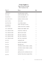
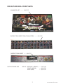
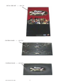
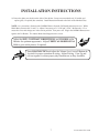
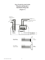
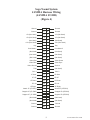
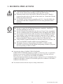
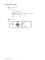
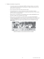
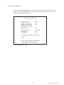
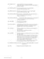
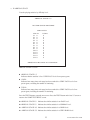
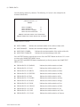
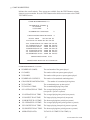
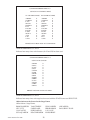
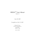
www.seuservice.com
1ST PRINTING SEPT 01
Universal Kit
Kit Installation Instructions
& Service Manual
Switchable FROM High Resolution 31K
TO Standard (Low) Resolution 15.75K.
1 - 2 PLAYER GAME
SEGA ENTERPRISES, INC. USA
MANUAL NO. 999-1310
VISIT OUR WEBSITE!
Virtua Fighter 4
Sega Naomi System
Kit Contains List
Part #
Desc
Qty
400-5397-01
NAOMI POWER SUPPLY
1
838-13616
AUDIO POWER AMP 2 CH
1
560-5407-UL
AUDIO XFORMER 120V
1
838-13683-93CV1
JAMMA I/O BD (NAOMI)
1
600-7141-200
USB CABLE
1
600-7009-2500
VGA VIDEO CABLE
1
840-0080D-01
ASSY CASE NAT VF4 USA
1
600-7247-500
CABLE SCSI TYPE 2 500MM
1
LOC. PURCHASE
SERVICE SWT BRKT ASSY
1
LOC. PURCH. HAPP
JOYSTICK, COMP. GR
2
LOC. PURCH. HAPP
SWITCH, PB LARGE
2
LOC. PURCH. HAPP
BUTTON, COMP. GR
2
LOC. PURCH. HAPP
BUTTON, COMP. BLU
2
LOC. PURCH. HAPP
BUTTON, COMP. RED
2
999-1312
MARQUEE ART
1
999-1313
INSTRUCTION SHEET
1
999-1314
SIDE DECALS
2
999-1315
CONTROL PANEL OVERLAY (DED)
1
999-1316
CONTROL PANEL OVERLAY (GEN)
1
999-1310
VF4 MANUAL
1
999-1317
(METALPLATE) CONTROL PNL VS3
1
999-1319
INSTRUCTION FOR CHARACTERS
1
1
www.seuservice.com
Virtua Fighter 4
Sega Naomi System
Kit Contains List
Part #
Desc
Qty
999-1320
DECAL FOR DEFENSE (GREEN)
2
999-1321
DECAL FOR PUNCH (BLUE)
2
999-1322
DECAL FOR KICK (RED)
www.seuservice.com
2
2
DESIGNED RELATED PARTS
MARQUEE ART -----
999-1312
INSTRUCTION SHEET FOR CHARACTERS ----- 999-1319
INSTRUCITON SHEET ---- 999-1313
NOT PICTURED ARE
DECAL DEFENSE (GREEN) ---- 999-1320
PUNCH (BLUE)
---- 999-1321
KICK (RED)
---- 999-1322
3
www.seuservice.com
DECAL SIDE ART ---- 999-1314
CONTROL PANEL ---- 999-1315
CONTROL PANEL ---- 999-1316
www.seuservice.com
4
Feb 9. 2000
120
SERVICE BULLETIN
SEGA Service Department
45133 Industrial Drive
Fremont, Ca. 94538
http://www.seuservice.com
Phone: 415.701.6580
Fax: 415.701.6594
SPECIAL NOTICE FOR
ALL SEGA NAOMI KITS
PROBLEM:
The SEGA Naomi Game kits are actually ‘JAMMA Dependent’. What this means exactly is they will only
install into existing JAMMA Cabinets. If an operator tries to install these kits into a Non-JAMMA cabinet,
they will first have to bring the wiring up to JAMMA Standards.
SOLUTION:
°
°
Step 1 Disconnect the games original DC Power Supply. You may only use the power supply provided
with your kit. Be sure to set the voltages going to your Game BD to 5.1 and 3.3 volts DC to assure proper
operation ( Measure on Square Connector at Game BD. Yellow = 5vdc / Brown = 3.3vdc / White = Gnd )
Step 2 You MUST USE THE COIN METER SUPPLIED WITH YOUR KIT to assure proper Coin
acceptance. A minimum 18 Gauge wire should be used from the Coin Meter 1 output line on your
JAMMA Harness. The 5vdc ( Yellow ) wire found in the wiring bag of your kit MUST BE USED for the
supply voltage to the meter.
Not following the directions provided herein may cause your game to malfunction.
All electrical work should be performed by the site’s Serviceman or Technician.
In order to prevent an electric shock and short circuit, be sure to turn power off before performing
work or touching the interior parts of the product.
Be careful so as not to damage wirings. Damaged wiring can cause an electric shock or short circuit
accident.
Do not touch places other than those specified. Touching places not specified can cause an electric
shock or short circuit accident.
If you have any questions please contact the SEGA Service Department at the numbers given above.
5
www.seuservice.com
INSTALLATION INSTRUCTIONS
1) First. Remove all access panels from the game. Locate the original game Logic PCB’s & Power
Supply and remove from the Cabinet by first disconnecting all harnesses from the boards. (You need
only to splice in the Main Power (110v AC) into the 3-Pin Connector (GRN/WHT/BLK).)
2) Remove all existing game harnesses (we suggest using New Jamma Harnesses (NOT contained in the
kit) to ensure reliability).
3) Locate the most convenient and open area of the cabinet to mount the Virtua Fighter 4 Naomi
System Assembly. Make sure this area is free and clear of all cable harnesses and grounds, cable
clamps, etc.
Vacuum out or clean bottom of cabinet of dirt & miscellaneous parts (e.g.
screws, loose coins / tokens, etc.).
Remove all exterior decals and repair any cabinet damage. Repaint
cabinet if necessary. Remove the Monitor Plexi or if your game plexi has
Silk-screened artwork, you will need to strip it off.
4) Connect the JAMMA Harnesses to the JVS-JAMMA Interface Boards. Separate the wires from each
other (i.e. Control Panel, Video, Speaker, Power Supply). Run the various harnesses to the part of the
cabinet they go to ensuring they are dressed properly & secured to the cabinet. Locate the Volume/
Speaker/Coin Meter Cable and connect to your existing Switch Bracket or use the new one included
with the kit. Note: If you are using a VGA Compatible Monitor you can run your VGA Cable directly
to the monitor or connect it to your JVS JAMMA Interface for RGB Conversion to your JAMMA
Cables.
5) Remove Marquee from cabinet and cut to fit the new Virtua Fighter 4 Marquee in place.
REPLACE old Joysticks & Buttons with the NEW ones supplied in Kit.
6) First remove all Joystick and Button assemblies from the Control Panel. Remove Lexan and Control
Panel Overlay. Proceed to clean surface of the Control Panel by removing all adhesive and dirt. Fill
in or plug up existing button holes to set up a blank work area for your new controls.
7) Install the new Control Panel Overlay by carefully peeling off the paper backing and laying down on
the panel. Smooth it out, starting in the center and working your way to the edges (removing all of
the trapped air pockets). If necessary, cut the edges of the overlay excess and fold under panel.
8) Cut out the button and Joystick Holes. Install Joystick and buttons from kit into the Control Panel
and tighten down. Connect all game harness wires to switches and buttons.
www.seuservice.com
6
INSTALLATION INSTRUCTIONS
9) Proceed to place new decals on the sides of the cabinet. Locate a new monitor bezel, if needed, and
replace glass, if required (due scratches). Install Instruction Placard to the back of the Monitor Glass.
NOTE: As a precaution, disconnect the JAMMA Harness from the I/O Boards and turn power on. With a
Multi-Meter, measure the 5v and 3.3v. Adjust if necessary to 5.15v DCand 3.3vDC. Measure the +12 to
ensure the wires and voltages are in the correct position. Turn power off. Plug in the JAMMA Harness once
again to the I/O Boards. The Attract Mode should appear on the screen.
Adjust the SIZE, CONTRAST, BRIGHTNESS, and COLORS on the
Monitor for optimum appearance. Adjust VERTICAL/HORIZONTAL
Hold to get a stable picture, if required.
Enter DIAGNOSTICS and adjust the Volume Level, test all Buttons &
Joystick for proper operation & wiring. Adjust Pricing. Coin-Up and
test out a game to ensure proper play functions are as they should be.
7
www.seuservice.com
Sega Naomi System Switch
Bracket and Speaker
Installation Diagrams
(Figure 3)
To CN1 of
Amplifier Board
JAMMA Pin 8
Pin 1
Yellow Wire from Extra
Harness (+5v)
Pin 4
Pin 5
WHT/RED
GRN/RED
YEL/RED
_
+
Coin Meter
Service
Test
JAMMA Pin
JAMMA Pin
JAMMA Pin
Volume
GRY/RED
From CN2 of
Amplifier Board
From CN4 of
Amplifier Board
www.seuservice.com
ORG/RED
GRY/BLUE
ORG/BLUE
8
R
1
15
Left
Speaker
Right
Speaker
Sega Naomi System
JAMMA Harness Wiring
(JAMMA I/O BD)
(Figure 4)
Ground
1
A
Ground
Ground
2
B
Ground
+5v (Not Used)
3
C
+5v (Not Used)
+5v (Not Used)
4
D
+5v (Not Used)
(Not Used)
5
E
(Not Used)
+12v (Not Used)
6
F
+12v (Not Used)
Key
7
H
Key
Coin Meter 1
8
J
Coin Meter 2
(Not Used)
9
K
(Not Used)
(Not Used)
10
L
(Not Used)
(Not Used)
11
M
(Not Used)
Video Red
12
N
Video Green
Video Blue
13
P
Video Sync
Video Ground
14
R
Service
Test
15
S
(Not Used)
Coin 1
16
T
Coin 2
1P Start
17
U
2P Start
1P UP
18
V
2P UP
1P Down
19
W
2P Down
1P Left
20
X
2P Left
21
Y
2P Right
Attack 1P (1P SW1)
22
Z
Attack 2P (2P SW1)
Grapple 1P (1P SW2)
23
a
Grapple 2P (2P SW2)
Support 1P (1P SW3)
24
b
Support 2P (2P SW3)
(Not Used)
25
c
(Not Used)
(Not Used)
26
d
(Not Used)
Ground
27
e
Ground
Ground
4
28
f
Ground
1P Right
9
www.seuservice.com
Sega Naomi System
Filter Board Information
Connector Description etc.
PSW2 PSW1
Service
Switch
DIPSW1
CN4
CN3
CN2
CN1
Test
Switch
Preamp Level
Audio Out
1
2
3
VGA Level
Video Out
4
Setting for High
Resolution 31KHZ
1 -4 off
1
2
3
Setting for Standard
Resolution 15KHZ
1 on 2-4 off.
www.seuservice.com
10
Power Connectors
1. HANDLING PRECAUTIONS
To prevent electric shock or IC Board malfunctioning, be sure to turn off the
power for the cabinet when installing or removing the IC Board.
Extraneous matter such as dust on the IC Board can cause the IC Board to
generate heat and result in a fire due to short circuit, etc. Ensure the IC Board
surfaces are always kept clean.
Use NAOMI 2 for the cabinets compatible with JVS. Using NAOMI for the
cabinet other than those compatible with JVS can cause generation of heat
and a fire.
STOP
IMPORTANT
Be sure to connect the IC Board and connectors completely. Insufficient
insertion can damage IC Board, etc.
For the IC Board circuit inspection, only the use of Logic Tester is permitted.
The use of ordinary testers is not permitted as these can damage the IC Board.
Do not subject the IC Board to static electricity when installing the IC Board
in the cabinet or when connecting wire harness connectors to the IC Board.
When soldering buttons, etc. to the wire harnesses, be sure to remove the wire
harnesses from the IC Board so as not to subject the IC Board to heat.
Using NAOMI 2 without the Shield Case can cause electric wave trouble. Be
sure to use NAOMI 2 together with the accessory Shield Case.
The monitor frequency corresponding to NAOMI 2 is 15kHz or 31kHz.
NAOMI 2 can not be used for the cabinet incorporating a monitor or projector
not corresponding to 15kHz or 31kHz.
Concerning the display of JAMMA VIDEO STANDARD:
JAMMA VIDEO STANDARD adopted by NAOMI 2 is referred to as JVS. As against this
Standard, the conventional JAMMA STANDARD which employs 56P Edge Connectors
adopted by ST-V, etc. is displayed as Old JAMMA STANDARD.
The specific Manual attached to each game sometimes displays JVS as JV STANDARD, New
JAMMA STANDARD, or JAMMA 2 STANDARD against OLD JAMMA STANDARD as
JAMMA STANDARD, JS, etc.
The contents herein described are subject to change without notice.
11
www.seuservice.com
2. SPECIFICATIONS
1 ON-SCREEN DISPLAY
Monitor Position
HORIZONTAL
Horizontal Synchronous Frequency
31 / 15 kHz
2 CONTROL PANEL
8WAYS
START
KICK
PUNCH
DEFENSE (GUARD)
www.seuservice.com
12
3. CONTENTS OF GAME
3 -1 OUTLINE OF THE GAME
• You, as a martial art fighter, play in a tournament.
• You operate a playing character to fight against an opponent computer-operated character
(CPU).
• The playing characters covers 13 selectable regular characters and 1 boss character.
3 - 2 PLAYING PROCEDURE
1 Total 13 characters are available. Out of them you select one character to start the game.
2 At each stage you play a match against a computer-operated character.
3 Winning a match
• Each match consists of multiple rounds. You win a match when the number of your gained
rounds reaches a preset value.
• When you win a match at any stage, you can proceed to a next stage and play a match
against a new computer-operated character.
4 Gaining a round
You can gain a round when either of the following events occurs.
• You successfully reduce the opponent's energy to 0 (zero).
• Your energy remains much more than the opponent's energy when the limit time has become
0 (zero).
• You turn the opponent out of the ring.
When you and the opponent have drawn (that is, at the end of a round, both have a same level of
energy or have knocked each other at the same time), both can gain the round exceptionally.
When you and the opponent have drawn under a sudden death state (that is, the number of the
gained rounds is equal to each other and either can win the match by obtaining one more round),
either with more energy becomes a winner of the match.
5 When the GAME becomes OVER
The game is over when either of the following events occurs.
• You lose a match against a computer-operated character.
• You finish all the 14 stages: 13 stages, each with a regular computer-operated character, and
1 stage with a boss computer-operated character.
6 Continuing the game
You can continue the game as follows.
• When you lose a match, the CONTINUE screen appears.
• Insert the credit coins before the limit time is counted down to 0 (zero) on the CONTINUE
screen, and press the start button. Then, you can continue the game (or resume the first round
of the stage where you lost a match).
13
www.seuservice.com
3 - 3 CHARACTER SELECT SCREEN
You select one out of the 13 available characters.
Each character indicates its difficulty level: novice, intermediate, or expert.
Place the lever in an upper, lower, left, or right position to migrate from character to
character, and press either of the punch, kick, and defense buttons to select a character.
Hold down the start button and press either of the punch, kick, and defense buttons to toggle
between 1P character's color and 2P character's color.
3 - 4 GAME-PLAYING SCREEN
Limited Time of the Round The round ends when the
time is counted down to 0.
1P Energy Gauge Reduced when damaged.
The round ends when the gauge reads 0.
2P Energy Gauge
Obtained Rounds of 1P
1P Character
2P Character
Obtained Rounds of 2PYou win
if you obtain all the rounds.
www.seuservice.com
14
3 - 5 BASIC OPERATIONS OF THE CONTROLS
The following explains the operation for a 1P character. For a 2P character, read right and left
reverse.
The following abbreviations are used herein.
P: Punch button
K: Kick button
G: Defense (Guard) button
+: Operating the two or more controls at the same time
• P:
Punching attack
• K:
Kicking attack
• G:
Defending upper and middle parts
• Lever in a lower position + G: Defending lower part
(Note: The opponent may attack you at your upper, middle, or lower part. You must defend
your upper, middle, or lower part accordingly.)
• Lever in a right position: Moving forwards
• Lever in a left position: Moving backwards
• Lever in an upper position: Dodging away from you
• Lever in a lower position instantly: Dodging toward you
• P or K + lever in an upper position: Jumping upwards
• P or K + lever in an upper right position: Jumping diagonally forwards
• P or K + lever in an upper left position: Jumping diagonally backwards
• Lever in a right position two times quickly: Dashing forwards
• Lever in a left position two times quickly: Dashing backwards
• Lever in a lower right position two times quickly: Crouching and dashing forwards
• Lever in a lower left position: two times quickly: Crouching and dashing backwards
• Lever held in a lower position: Crouching
• P + G when you are close to the opponent: Throwing
• P + G when the opponent is throwing you: Escaping the throw (slipping)
• Lever in an upper position + P for the downed opponent: Jumping and attacking the downed
opponent
• Repeated G when you are downed: Standing up quickly
• Repeated K when you are downed: Kicking attack immediately after quickly standing up
• Lever in a left position when you are downed: Rolling backwards and standing up
• Continuously operated lever when you are faltering: Unfaltering quickly
15
www.seuservice.com
3 - 6 SPECIAL OPERATIONS OF THE CONTROLS
Dodging/Attacking
Immediately after surely dodging by a lever operation, you attack an opponent. Thus you can
use the combination of dodging/attacking skills.
Lever in an upper position + P + K + G: Dodging away from you and attacking
Lever in a lower position instantly + P + K + G: Dodging toward you and attacking
Ukemi (safe ways of falling down)
The ukemi enables you to regain your balance just when landing and to immediately attack an
opponent. This skill lessens damage to you. Thus you can escape from the crunch and rather
earn a chance to counterattack. You may be just downed or use the ukemi, whichever is
tactically desirable in each situation.
P + K + G immediately before you are downed: Ukemi
Attacking with the accumulated energy
Using the energy accumulated for a little time, you can destroy an opponent's defenses. This
high-risk, high-return skill enhances your tactical capabilities. Special commands, one each with
a character, are available to activate this function.
Fighting by the walls
• You may damage and destroy the walls. Thereby you can change the state of the ring as
tactically required.
• The opponent may falter when you throw him/her against the walls. This enables you to use
the combination (Combo) skills.
www.seuservice.com
16
3 - 7 PERSON-VS-PERSON (VS) MATCHS
• A new player may join you in playing the GAME or selecting a character. As a result the
system suspends the current one-person match against a computer-operated character and
starts a person-vs-person match.
• The new player must insert the credit coins before joining.
• After playing the person-vs-person match only the winner can continue to play the
suspended match: one-person match against a computer-operated character. He/she resumes
the first round of the suspended match.
• When you have set the STAGE item to RANDOM on the GAME ASSIGNMENTS screen,
the built-in computer (CPU) randomly selects a stage.
• When you have set the STAGE item to SELECTIVE on the GAME ASSIGNMENTS
screen, the newly joined player selects a stage. (For more information see the chapter 4, B, b.
"GAME ASSIGNMENTS.") To select, he/she places the lever in an upper, lower, left, or
right position to migrate from stage to stage, and presses either of the punch, kick, and
defense buttons.
PERSON-VS-PERSON (VS) MATCHS•STAGE SELECT SCREEN
17
www.seuservice.com
4. TEST MODE
A. SYSTEM MENU
When settings are changed in SYSTEM ASSIGNMENTS, COIN
ASSIGNMENTS, and GAME ASSIGNMENTS of GAME TEST MODE, be sure
to exit from the test mode of SYSTEM MENU screen. The contents of setting
changes are stored in the IC on the BOARD when exiting from the Test Mode. If
the power is turned off in the Test Mode (before exiting), the contents of setting
changes are ineffective. In this case, the settings remain unchanged.
STOP
IMPORTANT
This test mode mainly allows the IC Board to be checked for accurate functioning, monitor
color to be adjusted as well as COIN ASSIGNMENTS and GAME ASSIGNMENTS to be
adjusted.
1) Connect the power, and press the TEST Button. Then the following SYSTEM MENU screen
appears.
1 4 4 4 2 4 4 4 3
For the COIN ASSIGNMENTS, set as follows:
COIN CHUTE TYPE: INDIVIDUAL
COIN/CREDIT SETTING: at discretion
SEQUENCE: at discretion
1 2 3
RAM TEST
JVS TEST
SOUND TEST
C.R.T. TEST
SYSTEM ASSIGNMENTS
COIN ASSIGNMENTS
BOOKKEEPING
BACKUP DATA CLEAR
CLOCK SETTING
1 4 2 3
SYSTEM MENU
For the SYSTEM ASSIGNMENTS, do not
change the following default settings:
CABINET TYPE: 2 PLAYER(S)
MONITOR TYPE: HORIZONTAL
SERVICE TYPE: COMMON
BOOKKEEPING 2/2 means as follows:
P1 SEQ 1: Play frequency of Player 1
P2 SEQ 2: Frequency of CONTINUE by Player 1
P3 SEQ 3 ~ 8: Not Used
ROM BOARD TEST
GAME TEST MODE
[X X X X X X X X X ]
-> EXIT
SELECT WITH SERVICE BUTTON
AND
PRESS TEST BUTTON
www.seuservice.com
Out of the COIN ASSIGNMENTS items, the SEQUENCE # items means as
follows:
SEQUENCE 1: The number of credits required for starting the game
SEQUENCE 2: The number of credits required for continuing the game
SEQUENCE 3 to 8: Not Used
18
2) Press the SERVICE Button to move the -> mark to any desired item, and press the TEST
Button.
3) Press the SERVICE Button to move the -> mark to GAME TEST MODE item, and press the
TEST Button. Then the GAME TEST MENU screen appears that enables to test the items
specific to this game. For the details, see the following pages.
4) After testing, select the EXIT and press the TEST Button. The game advertising screen
reappears.
NOTE: For more information about the SYSTEM MENU screen, see the NAOMI 2 Service
Manual.
B. GAME TEST MODE
Press the SERVICE Button to move the arrow mark to the GAME TEST MODE item on the
SYSTEM MENU screen, and press the TEST Button. The GAME TEST MENU screen,
specific for this game, opens.
Press the SERVICE Button to move the arrow mark to a desired test item on the GAME TEST
MENU screen, and press the TEST Button to open the related screen.
After testing, move the arrow mark to the EXIT item and press the TEST Button. The SYSTEM
MENU screen reappears
VF4 GAME TEST MENU
-> INPUT TEST
GAME ASSIGNMENTS
1P ARRIVAL STAGE
CHARA DATA
TOTAL DATA
VS DIAGRAM
GAME BOOKKEEPING
BACKUP DATA CLEAR
EXIT
SELECT WITH SERVICE BUTTON
AND PRESS TEST BUTTON
GAME TEST MENU Screen
19
www.seuservice.com
a. INPUT TEST
This test displays the state of each switch and button.
If the switch goes ON when the switch/button is pressed, it is satisfactory.
Press SERVICE Button and TEST Button simultaneously to have the MENU return on
to the screen.
INPUT TEST
PLAYER
1P
2P
START
UP
DOWN
LEFT
RIGHT
OFF
OFF
OFF
OFF
OFF
OFF
OFF
OFF
OFF
OFF
GUARD
PUNCH
KICK
OFF
OFF
OFF
OFF
OFF
OFF
TEST
OFF
SERVICE OFF
PRESS SERVICE+TEST BUTTON TO EXIT
INPUT TEST Screen
START
KICK
UP
PUNCH
RIGHT
DEFENSE (GUARD)
LEFT
DOWN
CONTROL PANEL
www.seuservice.com
20
b. GAME ASSIGNMENTS
Allows game difficulty adjustments, time setting, etc. to be changed. Move the arrow to the
desired item by SERVICE Button and press the TEST Button to change the setting. Select
EXIT to return to the MENU screen.
GAME ASSIGNMENTS
ENEMY LEVEL
ENERGY MAX(1P)
ENERGY MAX(VS)
MATCH COUNT(1P)
MATCH COUNT(VS)
TIME LIMIT
EASY
200
200
2
2
30
STAGE SELECT
CONTINUE
VS FINISH
RANDOM
ON
OFF
RETURN TO DEFAULT SETTING
-> EXIT
SELECT WITH SERVICE BUTTON
AND PRESS TEST BUTTON
GAME ASSIGNMENTS Screen
21
www.seuservice.com
ENEMY LEVEL:
ENERGY MAX (1P): Sets the energy (initial value) in a one-person game.
180 g200 g220 g240 (Default: 200)
ENERGY MAX (VS): Sets the energy (initial value) in a person-vs-person game.
180 g200 g220 g240 (Default: 200)
MATCH COUNT (1P):Sets the number of the rounds that a player aims to gain for winning the related match in a one-person game.
2 g3 g4 g5 (Default: 2)
MATCH COUNT (VS):
Sets the number of the rounds that a player aims to gain for
winning the related match in a person-vs-person game.
2 g3 g4 g5 (Default: 2)
TIME LIMIT:
Sets the limit time of a match.
30 g45 g60 (Default: 30)
STAGE SELECT:
Sets the method of selecting a stage in a person-vs-person game.
RANDOM indicates an automatic selection by the computer.
RANDOM gSELECTIVE (Default: RANDOM)
CONTINUE:
Determines whether you can continue to play the lost match in a
one-person game.
ON indicates that you can play the lost match.
ON gOFF (Default: ON)
VS FINISH:
Determines whether to finish the game after you have successfully
played the matches.
The *WIN settings indicate that the game is finished for both the
players after you have won consecutively * times (Note that the *
mark is equal to 1 up to 10 or the number of winning matches as
below). These settings are prepared for some competitions or
events. Usually, therefore, set this item to OFF.
OFF g1 WIN g2 WIN g3 WIN g4 WIN g5 WIN g6 WIN
g7 WIN g8 WIN g9 WIN g10 WIN (Default: OFF)
RETURN TO DEFAULT SETTING: Resets all the GAME ASSIGNMENTS items to the
default values.
EXIT:
www.seuservice.com
Sets the difficulty level of the one-person match.
VERY EASY gEASY gNORMAL gHARD gVERY HARD
(Default: NORMAL)
Returns to the GAME TEST MENU screen.
22
c. 1P ARRIVAL STAGE
Lists the playing statistics by difficulty level.
ARRIVAL STAGE 1/5
1P GAME STAGE RECORDS
VERY EASY
TOTAL
#1 0
#2 0
#3 0
#4 0
#5 0
#6 0
#7 0
#8 0
#9 0
#10 0
#11 0
#12 0
#13 0
#14 0
1COIN
0
0
0
0
0
0
0
0
0
0
0
0
0
0
PRESS TEST BUTTON TO CONTINUE
ARRIVAL STAGE 1/5 Screen
ARRIVAL STAGE 1/5:
Indicates that the statistics is for a VERY EASY level of one-person game.
1COIN:
Indicates how many times each stage has been reached in a VERY EASY level of oneperson game, excluding the number of continuing.
TOTAL:
Indicates how many times each stage has been reached in a VERY EASY level of oneperson game, including the number of continuing.
Press the TEST Button to open the next screen. Press the TEST Button on the last 5/5 screen to
return to the GAME TEST MENU screen.
ARRIVAL STAGE 2/5: Indicates the similar statistics in an EASY level.
ARRIVAL STAGE 3/5: Indicates the similar statistics in a NORMAL level.
ARRIVAL STAGE 4/5: Indicates the similar statistics in a HARD level.
ARRIVAL STAGE 5/5: Indicates the similar statistics in a VERY HARD level.
23
www.seuservice.com
d. CHARA DATA
Lists the playing statistics by character. The following 1/13 screen is the example for the
character named Akira.
CHARA DATA 1/13
AKIRA
MAX COMBO
MAX DAMAGE
MAX WALL COMBO
MAX WALL DAMAGE
0
0
0
0
PRESS TEST BUTTON TO CONTINUE
PRESS SERVICE+TEST BUTTON TO EXIT
CHARA DATA 1/13 Screen
MAX COMBO:
Indicates the maximum number of the combos without walls.
MAX DAMAGE:
Indicates the maximum damages without walls.
MAX WALL COMBO:
Indicates the maximum number of the combos with walls.
MAX WALL DAMAGE:
Indicates the maximum damages with walls.
Press the TEST Button to open the next screen. Press the TEST Button on the last 13/13 screen
to return to the GAME TEST MENU screen.
Press the TEST and SERVICE Buttons simultaneously to directly return to the GAME TEST
MENU screen.
CHARA DATA 2/13 SARAH:
Indicates the similar statistics on Sarah.
CHARA DATA 3/13 LAU:
Indicates the similar statistics on Lau.
CHARA DATA 4/13 SHUN:
Indicates the similar statistics on Shun.
CHARA DATA 5/13 JEFFRY:
Indicates the similar statistics on Jeffry.
CHARA DATA 6/13 PAI:
Indicates the similar statistics on Pai.
CHARA DATA 7/13 JACKY:
Indicates the similar statistics on Jacky.
CHARA DATA 8/13 KAGE:
Indicates the similar statistics on Kage.
CHARA DATA 9/13 LION:
Indicates the similar statistics on Lion.
CHARA DATA 10/13 WOLF:
Indicates the similar statistics on Wolf.
CHARA DATA 11/13 AOI:
Indicates the similar statistics on Aoi.
CHARA DATA 12/13 LEI:
Indicates the similar statistics on Lei Fei.
CHARA DATA 13/13 VAN:
Indicates the similar statistics on Vanessa.
www.seuservice.com
24
e. TOTAL DATA
Lists the entire statistics by character.
TOTAL DATA
SERIES OF WINS
WINS OF CHARA
1ST
2ND
3RD
4TH
5TH
6TH
7TH
8TH
9TH
10TH
AKIRA
SARAH
LAU
SHUN
JEFFRY
PAI
JACKY
KAGE
LION
WOLF
AOI
LEI
VAN
20
20
20
20
19
19
19
18
18
18
AKIRA
SARAH
LAU
SHUN
JEFFRY
PAI
JACKY
KAGE
LEI
AOI
0
0
0
0
0
0
0
0
0
0
0
0
0
PRESS TEST BUTTON TO EXIT
TOTAL DATA Screen
SERIES OF WINS: Indicates the number of the consecutive winnings for each character.
WINS OF CHARA: Indicates the accumulated number of the winnings for each character.
Press the TEST Button to return to the GAME TEST MENU screen.
25
www.seuservice.com
f. VS DIAGRAM
Illustrates a matching diagram.
VS DIAGRAM
-------------------------------------------------------|AKI|SAR|LAU|SHN|JEF|PAI|JAK|KAG|LIO|WOL|AOI|LEI|VAN|
---+---+---+---+---+---+---+---+---+---+---+---+---+---AKI| | | | | | | | | | | | | | 0.00( 1
---+---+---+---+---+---+---+---+---+---+---+---+---+---SAR| | | | | | | | | | | | | | 0.00( 1
---+---+---+---+---+---+---+---+---+---+---+---+---+---LAU| | | | | | | | | | | | | | 0.00( 1
---+---+---+---+---+---+---+---+---+---+---+---+---+---SHN| | | | | | | | | | | | | | 0.00( 1
---+---+---+---+---+---+---+---+---+---+---+---+---+---JEF| | | | | | | | | | | | | | 0.00( 1
---+---+---+---+---+---+---+---+---+---+---+---+---+---PAI| | | | | | | | | | | | | | 0.00( 1
---+---+---+---+---+---+---+---+---+---+---+---+---+---JAK| | | | | | | | | | | | | | 0.00( 1
---+---+---+---+---+---+---+---+---+---+---+---+---+---KAG| | | | | | | | | | | | | | 0.00( 1
---+---+---+---+---+---+---+---+---+---+---+---+---+---LIO| | | | | | | | | | | | | | 0.00( 1
---+---+---+---+---+---+---+---+---+---+---+---+---+---WOL| | | | | | | | | | | | | | 0.00( 1
---+---+---+---+---+---+---+---+---+---+---+---+---+---AOI| | | | | | | | | | | | | | 0.00( 1
---+---+---+---+---+---+---+---+---+---+---+---+---+---LEI| | | | | | | | | | | | | | 0.00( 1
---+---+---+---+---+---+---+---+---+---+---+---+---+---VAN| | | | | | | | | | | | | | 0.00( 1
-------------------------------------------------------PRESS TEST BUTTON TO EXIT
VS DIAGRAM Screen
The percentage of wins is indicated on the second rightmost column of the screen. The order of
wins percentage is indicated on the rightmost column of the screen.
Press the TEST Button to return to the GAME TEST MENU screen.
Abbreviations on the Screen for the Character Names
Abbreviations: Character Names
AKI:
AKIRA
SAR:
SARAH
LAU:
LAU
SHN:
SHUN
JEF:
JEFFRY
PAI:
PAI
JAK:
JACKY
KAG:
KAGE
LIO:
LION
WOL:
WOLF
AOI:
AOI
LEI:
LEI FEI
VAN:
VANESSA
www.seuservice.com
26
g. GAME BOOKKEEPING
Indicates the overall statistics. Three screens are available. Press the TEST Button to migrate
from one screen to another. Press the TEST Button on the third screen to return to the GAME
TEST MENU screen.
GAME BOOKKEEPING 1/3
NUMBER OF GAMES 0
1P GAMES
0
VS GAMES
0
NUMBER OF CONTINUE
0
CHALLENGE/PARTICIPATION
0
TOTAL TIME
0D 0H 0M 0S
TOTAL PLAY TIME 0D 0H 0M 0S
ALL AVERAGE PLAY
1P AVERAGE PLAY
1P LONGEST PLAY
1P SHORTEST PLAY
VS AVERAGE PLAY
VS LONGEST PLAY
VS SHORTEST PLAY
TIME
TIME
TIME
TIME
TIME
TIME
TIME
0H
0H
0H
0H
0H
0H
0H
0M
0M
0M
0M
0M
0M
0M
0S
0S
0S
0S
0S
0S
0S
OPERATING RATIO 0.0%
PRESS TEST BUTTON TO CONTINUE
GAME BOOKKEEPING (1/3) Screen
NUMBER OF GAMES:
The total number of the games played
1P GAMES:
The number of the one-person games played
VS GAMES:
The number of the person-vs-person games played
NUMBER OF CONTINUE:
The number of accumulated continuing-times
CHALLENGE/PARTICIPATION:
The number of accumulated joining-times
TOTAL TIME:
The accumulated power-up time period
TOTAL PLAY TIME:
The accumulated playing time period
ALL AVERAGE PLAY TIME: The averaged playing time period
(one-person + person-vs-person)
1P AVERAGE PLAY TIME:
The averaged playing time period (one-person)
1P LONGEST PLAY TIME:
The longest playing time period (one-person)
1P SHORTEST PLAY TIME:
The shortest playing time period (one-person)
VS AVERAGE PLAY TIME:
The averaged playing time period (person-vs-person)
VS LONGEST PLAY TIME:
The longest playing time period (person-vs-person)
VS SHORTEST PLAY TIME:
The shortest playing time period (person-vs-person)
OPERATING RATIO:
TOTAL PLAY TIME/TOTAL TIME (%)
27
www.seuservice.com
GAME BOOKKEEPING 2/3
USAGE OF CHARACTERS
1P CHARACTERS 2P CHARACTERS
AKIRA
SARAH
LAU
SHUN
JEFFRY
PAI
JACKY
KAGE
LION
WOLF
AOI
LEI
VAN
0
0
0
0
0
0
0
0
0
0
0
0
0
AKIRA
SARAH
LAU
SHUN
JEFFRY
PAI
JACKY
KAGE
LION
WOLF
AOI
LEI
VAN
0
0
0
0
0
0
0
0
0
0
0
0
0
PRESS TEST BUTTON TO CONTINUE
GAME BOOKKEEPING (2/3) Screen
Indicates how many times each character (for 1P and 2P) has been used.
GAME BOOKKEEPING 3/3
USAGE OF STAGE
#ROM
#NYC
#CAS
#SUI
#YAM
#UMI
#DUR
#DJO
#GDN
#HBR
#CAV
#NOH
#ARE
#BAN
0
0
0
0
0
0
0
0
0
0
0
0
0
0
PRESS TEST BUTTON TO EXIT
GAME BOOKKEEPING (3/3) Screen
Indicates how many times each stage has been used with the STAGE item set to SELECTIVE.
Abbreviations on the Screen for the Stage Names
Abbreviations: Stage Names
ROM:COLOSSEUM
NYC:CITY
CAS:CASTLE
SUI:AQUARIUM
www.seuservice.com
YAM:TEMPLE
UMI:ISLAND
DUR:HANGAR
DJO:GYMNASIUM
28
GDN:GARDEN
HBR:HARBOR
CAV:CAVE
NOH:SHRINE
ARE:ARENA
BAN:GREAT WALL
h. BACKUP DATA CLEAR
Clears the backup data from the screen.
BACKUP DATA CLEAR
YES
-> NO(CANCEL)
SELECT WITH SERVICE BUTTON
AND PRESS TEST BUTTON
YES:
Opens the BACKUP DATA CLEAR - COMPLETED screen for clearing the
following data. (The other data are not cleared.)
1P ARRIVAL STAGE
CHARA DATA
TOTAL DATA
VS DIAGRAM
GAME BOOKKEEPING
NO:
Returns to the GAME TEST MENU screen.
BACKUP DATA CLEAR
COMPLETED
PRESS TEST BUTTON TO EXIT
After clearing the backup data, the COMPLETED message appears.
Press the TEST Button to return to the GAME TEST MENU screen.
29
www.seuservice.com
5. GAME BOARD
Do not expose the Game Board so as to avoid causing an accident or
malfunctioning.
Static electricity discharge can damage electronic parts on the IC Board.
Before starting work by opening the Shield Case Lid, be sure to touch
grounded metallic surfaces to discharge physically charged static electricity.
When replacing the Game Board, refer to the CVT Manual and Instruction
Manual.
ASSY CASE ( 1 +
2 )
1 ASSY CASE NAOMI 2
MAIN BOARD
2 ROM CASE
www.seuservice.com
PART NO.
DESCRIPTION
840-0080D-01
840-0080D-02
840-0080D-03
840-0080D-04
ASSY CASE NAT VF4 USA
ASSY CASE NAT VF4 EXP
ASSY CASE NAT VF4 KOR
ASSY CASE NAT VF4 AUS
840-0046A-01
840-0046A-02
840-0046A-03
840-0046A-04
ASSY CASE NAOMI 2 MAIN BD USA
ASSY CASE NAOMI 2 MAIN BD EXP
ASSY CASE NAOMI 2 MAIN BD KOR
ASSY CASE NAOMI 2 MAIN BD AUS
840-0080C
ROM CASE NAT VF4
30
:
:
:
:
USA
OTHERS
KOREA
AUSTRALIA
TRANSFORMER
50
838-13616
17V
0V
0V
17V
120V
560-5407
AUDIO POWER AMP 2CH
JST VH 4P
P C
1 2 3 4 5 6
31
50
50
41
51
50
5k pot
71
50
10
30
50
50
10
30
[Extra] [GD ROM DRIVE]
72
92
120 Vac Input
0V
80
91
1
2
3
WHITE(U/P)
P C
3
1
Phono
plugs
2
JST VL
COIN COUNTER
To Extra
Yellow Wire
6
838-13683-91
1
31
To PIN 8
of Jamma
CN6
50 50 10 10 30 30
SW REGU FOR JVS
GND
GND
P C
400-5397
+3.3V
+5V
GND
GND
GND
+3.3V
+5V
+12V
P C
JST VL
SPEAKER OUTPUTS
www.seuservice.com
600-7141-050
10
20
30
40
50
60
70
80
A
B
C
D
E
JAMMA CONNECTIONS USED ARE:
° VIDEO OUT
° SWITCH INPUTS
° SWITCH GROUND RETURNS
° COIN COUNTER OUTPUT
600-7155
600-6743-050
NOTE: THERE ARE TO BE NO
CONNECTIONS MADE TO THE
JAMMA INTERFACE OTHER THAN
THE ABOVE FOREMENTIONED.
NAOMI KIT UNIVERSAL
WIRING DIAGRAM (1/1)
Warranty
Your new Sega Product is covered for a period of 90 days from the date of shipment. This certifies
that the Printed Circuit Boards, Power Supplies and Monitor are to be free of defects in workmanship or materials under normal operating conditions. This also certifies that all Interactive Control
Assemblies are to be free from defects in workmanship and materials under normal operating conditions. No other product in this machine is hereby covered.
Sellers sole liability in the event a warranted part described above fails shall be, at its option, to
replace or repair the defective part during the warranty period. For Warranty claims, contact your
Sega Distributor.
Should the Seller determine, by inspection that the product was caused by Accident, Misuse, Neglect, Alteration, Improper Repair, Installation or Testing, the warranty offered will be null and void.
Under no circumstances is the Seller responsible for any loss of profits, loss of use, or other damages.
This shall be the exclusive written Warranty of the original purchaser expressed in lieu of all other
warranties expressed or implied. Under no circumstance shall it extend beyond the period of time
listed above.