1
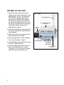
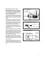
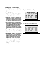
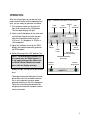
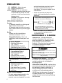
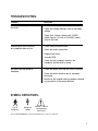
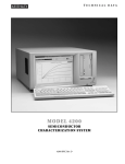
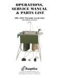
OPERATION AND MAINTENANCE
INSTRUCTION MANUAL
AEU-707A & AEU-707AV2 Implant / Surgery Systems
TABLE OF CONTENTS:
Introduction . . . . . . . . . . . . . . . . . . . . . . . . .1
Package Contents . . . . . . . . . . . . . . . . . . . .1
Setting Up the Unit . . . . . . . . . . . . . . . . . . .2
Operation Functions . . . . . . . . . . . . . . . . . .4
Speed Ranges . . . . . . . . . . . . . . . . . . . . . . .4
Operation . . . . . . . . . . . . . . . . . . . . . . . . . . .5
Sterilization and Maintenance . . . . . . . . . . .6
P.O. Box 1548 • Woodinville, WA 98072
8333 216 th Street S.E. • Woodinville, WA 98072
(425) 487-3157 • (800) 426-5913
www.aseptico.com • [email protected]
To prevent injury to people and damage to
property, please heed relevant warnings
and remarks. They are marked as follows:
Troubleshooting . . . . . . . . . . . . . . . . . . . . . .7
Symbol Definitions . . . . . . . . . . . . . . . . . . . .7
Warranty . . . . . . . . . . . . . . . . . . .Back Cover
SPECIFICATIONS:
Console Size:
WARNING: Serious injury or death may
result if ignored.
CAUTION: Damage to property or the
environment may result if
ignored.
NOTE:
Important additional
information and hints.
8.125” x 7.25” x 3.25”
(20.6375 cm x 18.415 cm
x 8.255 cm)
Console Weight: 3.75 lbs (1.6875 kg)
Power Source:
110V/120V 60Hz or
220V/250V 50Hz
Fuses:
1A/110V
0.5A/220V
Slo Blo Type
CLASSIFICATIONS:
• Internally Powered Equipment
• Type B Equipment
• Ordinary Equipment - degree of protection
against ingress of water
• Not suitable for use in the presence of a flammable anesthetic mixture with air or with oxygen or nitrous oxide.
WARNING: This device has been tested and found
to comply with the emissions requirements of IEC
60601-1-2:2001-09. These requirements provide
reasonable protection against harmful electromagnetic interference in a typical medical installation.
However, high levels of radio-frequency (RF) emissions from electrical devices, such as cellular
phones, may disrupt the performance of this device.
To mitigate disruptive electromagnetic interference,
position this device away from RF transmitters and
other sources of electromagnetic energy.
Your new Aseptico AEU-707A or AEU-707AV2 Implant / Surgery System is one
of the finest units available to the medical profession. The system features a
high torque brushless motor with digital RPM readout and self-contained irrigation pump. These features combine to make the perfect surgical motor and irrigation system for implant and other bone surgeries.
Congratulations!
This system is engineered to provide many years of reliable service. Please
read the instructions provided in this manual to receive the best and longest
service from your Aseptico equipment.
Separate manuals may be provided to cover the operation and maintenance of
hand-held pieces or other accessories for your unit.
PACKAGE CONTENTS:
• Electronic Control Console
• AE-4B-30 Autoclavable Brushless Micro Motor
• Autoclavable Motor Holder
• AE-7P On/Off Foot Control (Optional AE-18A variable speed foot control
available)
• AE-20 Autoclavable Irrigation Tubing Set
• 1/16 (AEU-707A) or 1/20 (AEU-707AV2) Reduction
Contra Angle Handpiece(s) (purchased separately)
• Irrigation Bag Hanger Rod
• Remote Power Cord
1
SETTING UP THE UNIT:
1. Unpack the console and check that the
voltage selector switch on the back is in the
proper position. Use the 110V position for
110-120V 60Hz voltages, and the 220V
position for the 220-250V 50Hz voltages.
For alternative voltages (220V-250V), confirm that the type of plug cap is correct for
the country of usage and carries the proper
certification markings. Correct cord is
shipped with the console.
2. Attach the remote power cord to the back of
the console and plug into a grounded electrical receptacle.
Fig.1 - Setup
BAG HANGER ROD
ELECTRONIC CONTROL
CONSOLE
FOOT
CONTROL
3. Connect the motor to the receptacle on the
lower front panel of the console.
4. Attach the appropriate "E-Type" handpiece
to the motor as shown in Figure 3.
5. Insert bag hanger rod into holder on the top
of the unit. Thread into place.
6. Attach the supplied foot control to the connector on the back of the unit marked
"Footswitch". An On / Off type or a variable
speed type foot control may be used.
2
MOTOR HOLDER
BRUSHLESS
MICRO MOTOR
MOTOR RECEPTACLE
7. Install irrigation tubing set in pump.
CAUTION: Never connect or disconnect
the bag spike to the irrigation bag over
the console. Waste spilled onto the console can damage the unit.
a. Thread tubing through pump following the
diagram in Figure 4. First remove the clear
pump cover by unscrewing the thumbscrew
on top.
b. Grasp the metal connector and tubing,
stretching the tubing slightly. Insert into the
slot on the top of the pump block, making
sure to position the metal connector on the
outside edge of the block as shown.
Fig.2 - Console Back
VOLTAGE
SELECTOR SWITCH
POWER
CORD IN
FOOT
SWITCH IN
Fig. 3 - Handpiece/Motor Connection
c. Guide the tubing around the rollers with
slight tension and insert into bottom slot on
the pump block.
d. While maintaining tension on the tubing,
check that tubing is centered on the rollers
and is completely tucked into slots on pump
block. Then replace clear pump cover by
sliding into position from front to back and
securing with the thumbscrew.
Fig.4 Irrigation Tubing Set
e. Route the remaining length of tubing to
the handpiece and connect to the irrigation
clip. Secure the tubing to the motor cord with
clip set provided.
f. Remove the protective cover from the irrigation bag and insert the bag spike into the
I.V. port. Hang the bag from the bag hanger
rod.
3
OPERATION FUNCTIONS:
1. Power Switch - Controls power On / Off to
console. When turned on, console should
light up.
2. Pump On / Off - Activates irrigation pump.
When turned on, the flow display will light
and the pump will activate when either
motor A or B is turned on.
3. Pump Flow - Increases or decreases the
irrigation flow. Push the Up/Down arrow to
increase flow or decrease flow. A visual display shows the approximate volume level.
4. RPM - Controls speed of motor and handpiece. Push the Up arrow to increase speed
and the Down arrow to decrease speed. A
visual display shows actual RPM. Ratio
selector must match exactly the ratio of the
hand piece being used for complete accuracy.
5. Forward / Reverse - Determines the rotation
of the motor and handpiece. A red LED light
displays the reverse rotation.
6. Ratio Selector - Calibrates the RPM display
to read accurately for up to four different
handpiece ratios. Push the ratio Up / Down
arrow until the indicator lights match the
handpiece ratio you are using. Different
handpiece ratios are required to obtain high
torque, low speeds used in surgery. The
speed ranges with a 30K motor are shown
in Figures 5a (AEU-707A) and 5b (AEU707AV2).
4
Fig. 5a - AEU-707A Speed Ranges
SPEED RANGES
1/1
1/16
1/64
1/256
4,000 - 30,000
300 - 1,900
50 - 470
10 - 120
RPM
RPM
RPM
RPM
Fig. 5b - AEU-707AV2 Speed Ranges
SPEED RANGES
1/1
1/16
1/20
1/256
4,000 - 30,000
300 - 1,900
200 - 1,500
10 - 120
RPM
RPM
RPM
RPM
OPERATION:
After the unit has been set up and you have
made yourself familiar with the operation functions, you are ready for operation as follows:
1. Turn the power switch on the lower left
front of the console to the 'ON' position.
The front panel display will light.
Fig.6 - Console Front (AEU-707AV2 shown)
FLOW
DISPLAY
RPM
DECREASE
RPM
DISPLAY
RPM
INCREASE
2. Attach a sterile handpiece to the motor and
set the Ratio Selector to match the gear
ratio of the hand piece being used (i.e.
1/16 for a 1:16 handpiece, or 1/20 for a
1:20 handpiece).
3. Adjust the Up/Down arrows on the RPM
display to the desired operating speed on
the RPM readout.
PUMP
ON/OFF
PUMP
FLOW
4. Switch the pump to the “ON” position. The
NOTE: The RPM display indicates true
bur speed when the Ratio Selector is
in the appropriate position. Make sure
the Ratio Selector Matches the handpiece ratio for display accuracy.
HANDPIECE
RATIO
SELECTOR
HANDPIECE
RATIO INDICATOR
FORWARD/REVERSE
SELECTOR
POWER
SWITCH
MOTOR
RECEPTACLE
display will light. Set the flow to the desired
level.
Thorough cleaning and lubrication of handpieces after each use and before sterilization is very important to ensure proper
operation and service life of the handpiece.
Follow the instructions provided with the
handpiece purchased for complete maintenance instructions.
5
STERILIZATION:
and install autoclaving plugs into the end of
the motor and motor cord connector as
shown below. The plugs are supplied with the
motor and cord.
WARNING - Sterilize the motor
between each patient use.
WARNING - Use of a sterilization
method or temperatures other than what
are prescribed may damage the motor
or present a risk of cross-contamination
between patients.
CAUTION - Do not soak or submerge
the motor in any liquid.
•
Loosely coil the motor cord when autoclaving. Avoid sharply bending the cord when
autoclaving.
• Always install the autoclaving plugs into motor
and motor connector before autoclaving.
STERILIZATION PROCEDURE:
Pre-clean
1) Thoroughly brush off any visible signs of
debris from the motor and cord.
2) Thoroughly clean the device with a moist
cloth or towel to remove any remaining signs
of debris.
Sterilize
3) Select one of the three following
sterilization methods (A. B. or C.):
Wrapped Sterilization – Place in an
appropriately sized sterilization pouch and
seal it.
A. Gravity Wrapped:
• Minimum Temperature:
132° C (270° F)
• Full Cycle Time: 20 minutes
• Minimum Dry time: 30 minutes
B. Prevacuum Wrapped:
• Preconditioning Pulses: 3
• Minimum Temperature:
132° C (270° F)
• Full Cycle Time: 4 minutes
• Minimum Dry time: 40 minutes
Flash Sterilization – For immediate use
only.
C. Gravity Unwrapped:
• Minimum Temperature:
132° C (270° F)
• Full Cycle Time: 10 minutes
No dry time is required for flash
sterilization.
MOTOR & CORD ASSEMBLY:
•
6
The entire motor and cord assembly is fully
autoclavable. Before autoclaving the
assembly, remove any handpiece from motor
Turn black connector ring only
• If the autoclaving plug for the motor becomes
difficult to remove or install, apply silicone grease
or similar lubricant to the O-rings.
NOTE: Call Aseptico, Inc. at 1-800-426-5913
for any questions or clarifications on this
sterilization procedure.
MAINTENANCE & CLEANING:
HANDPIECES - Thorough cleaning and
lubrication of handpieces after each use and
before sterilization is very important to ensure
proper operation and service life of the
handpiece. Follow the instructions provided with
the handpiece purchased for complete
maintenance instructions.
WARNING
• Do not attempt to disassemble the motor or motor connector.
• Do not oil or lubricate the motor.
• Do not attach a handpiece to the motor while motor is running.
• Do not bend motor cord sharply.
Failure to comply with any of the above instructions may
void your warranty
CONSOLE MAINTENANCE - The exterior of
the console may be cleaned by wiping with a
soft cloth moistened with mild detergent or
disinfecting solution.
IRRIGATION TUBING SETS - Irrigation tubing
sets can be removed from the pump and may
be sterilized by autoclave, chemclave, or
ethylene oxide gas processes. Follow the
manufacturer’s recommended procedure.
NEVER store the tubing sets in the pump for
extended periods of time. The tubing may
collapse and stick to itself creating a blockage
for future uses.
TROUBLESHOOTING:
Problem:
Correction:
Console does not light when
turned on:
• Check console to power connection.
• Check that Voltage Selector is set for the proper
voltage.
• Check fuse. If blown, replace with 1A/250V
slo-blo fuse for 110 volts, & 0.5A/250V slo-blo
fuse for 220 volts.
Console lights when turned on,
but handpiece does not turn:
• Check motor plug connection.
• Check foot switch connection.
• Depress foot switch.
• Increase RPM.
• Check that bur is properly seated in the
handpiece and the collet is closed.
No Water flow from pump to
handpiece:
• Check that pump is on and flow level is sufficient.
• Check that water container seal is completely
punctured.
• Make sure the irrigation tubing is properly installed
in pump and is in the correct direction.
SYMBOL DEFINITIONS:
Type B
Equipment
Dangerous
Voltage
Attention - Consult
Accompanying
Documents
The UL 2601 Standard Duty Cycle for Intermittent Use is 1 min. on / 5 min. off.
7
NOTES:
8
NOTES:
WARRANTY
Aseptico warrants its products against defects in material or workmanship for a period of
two (2) years, from date of original invoice. Some handpieces are warranted for one year
under the same conditions. Other handpieces and expendable components, such as air
turbines and light bulbs, are covered by shorter warranty periods, or have no warranty.
Aseptico's sole obligation under product warranty is (at its sole option and discretion) to
repair or replace any defective component or product in part or whole. Aseptico shall be
the sole arbiter of such action.
In the event of alleged defect under warranty, the purchaser is to notify Aseptico's
Customer Service Department promptly. Customer Service will provide instructions,
usually directing that the product be returned for service. Shipment to Aseptico and the
cost thereof is always the responsibility of the purchaser.
Accidental misuse, inappropriate installation, or failure to perform directed maintenance
voids the warranty. Deliberately defacing, modifying, or removing the serial number voids
the warranty.
Aseptico does not assume, under this warranty, any risks or liabilities arising from the
clinical use of its products, whether or not such use involves coincidental utilization of
products manufactured by others.
P/N: 420187
Rev. D, ECO 13447
Software 880082-01 (AEU-707A)
Software 880082-18 (AEU-707AV2)
09/2014
P.O. Box 1548 • Woodinville, WA 98072
8333 216 th Street S.E. • Woodinville, WA 98072
(425) 487-3157 • (800) 426-5913
www.aseptico.com • [email protected]
PRINTED IN THE USA