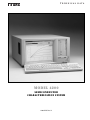
1
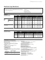
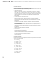
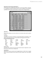
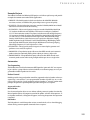
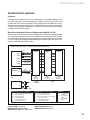
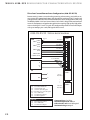
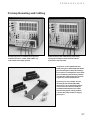
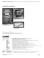
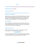
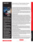
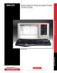
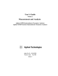
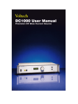
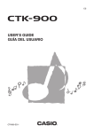
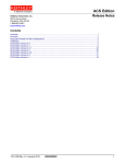
TECHNICAL DATA
MODEL 4200
SEMICONDUCTOR
CHAR ACTERIZ ATION SYSTEM
4200-SPEC Rev. D
M O D E L 4 2 0 0 - S C S S E M I C O N D U C T O R C H A R A C T E R I Z AT I O N S Y S T E M
Table of Contents
2
Introduction
3
Configuration Options
5
Hardware Specifications
7
KTE Interactive Software Tools
7 Microsoft Windows NT
8 The Keithley Interactive Test
Environment (KITE)
14 User Libraries (KULT)
17 System Configuration and Diagnostics
(KCON)
17 Keithley External Control Interface
(KXCI)
18
Accessories Supplied
18 Optional Instrumentation
18
Support Options
18 Calibration Options
19 Repair Options
19 Instrumentation Upgrades
19
Embedded PC Policy
20
Optional Accessories
20 Computer Options
20 Remote PreAmp Mounting Accessories
20 Other Accessories
20
C-V Options
21
Switch Matrix Options
21 Ultra-Low Current/Local Sense
Configuration (4200-UL-LS-XX)
22 Ultra-Low Current/Remote Sense
Configuration (4200-UL-RS-XX)
23 Low Current/Remote Sense
Configuration (4200-LC-RS-XX)
24 General-Purpose Remote Sense
Configuration (4200-GP-RS-XX)
25
Cabinets and Mounting Accessories
25
Additional Cables and Connectors
26
Front and Rear Panel Photographs
27
PreAmp Mounting and Cabling
28
4200-SCS Accessories
2
Introduction
The Model 4200-SCS provides a total system solution for DC characterization of semiconductor devices and test structures. This advanced
parameter analyzer provides intuitive and sophisticated capabilities for
semiconductor device characterization. The 4200-SCS combines
unprecedented measurement speed and accuracy with an embedded
Windows NT-based PC and the Keithley Interactive Test Environment
(KITE) to provide a powerful single-box solution.
The Keithley Interactive Test Environment allows users to gain familiarity quickly with tasks such as managing tests and results and generating reports. Sophisticated and simple test sequencing and external
instrument drivers simplify performing automated device and wafer
testing with combined I-V and C-V measurements.
The 4200-SCS is modular and configurable. The system supports up to
eight Source-Measure Units, including up to four high-power SMUs
with 1A/20W capability. An optional Remote PreAmp extends the resolution of any Source-Measure Unit from 100fA to 0.1fA.
TECHNICAL DATA
Configuration Options
The 4200-SCS supports many instrument configurations. The standard configuration
includes two medium-power Source-Measure Units (SMUs) and a Ground Unit.
Standard 4200-SCS Models
4200-SCS/F
Chassis
12.1˝ flat panel display
Two (2) Model 4200-SMU medium-power SMUs
One (1) Remote Sense Ground Unit
LAN, GPIB, RS-232, parallel port, hard disk, floppy disk drive, CD-ROM
4200-SCS/C
Chassis
Composite Front Bezel (CRT sold separately, Model 4200-CRT)
Two (2) Model 4200-SMU medium-power SMUs
One (1) Remote Sense Ground Unit
LAN, GPIB, RS-232, parallel port, hard disk, floppy disk drive, CD-ROM
Source-Measure Units
Each system can be configured with up to six additional SMUs, for a total of eight SMUs.
Two different SMU models are available: a medium-power (100mA, 2W) version (Model
4200-SMU) and a high-power (1A, 20W) version (Model 4210-SMU). The system can support up to four high-power SMUs. Optional SMUs are installed beginning with the
medium-power version first, then the high-power version.
4200-SCS Source-Measure Units
Maximum
Voltage
Maximum
Current
Maximum
Power
4200-SMU (medium-power)
210V
100mA
2W
4210-SMU (high-power)
210V
1A
20W
Remote PreAmp
The low current measurement capabilities of any SMU can be extended by adding an
optional Remote PreAmp (Model 4200-PA). The 4200-PA provides 0.1fA resolution by
effectively adding five current ranges to either SMU model. The PreAmp module is fully
integrated with the system; to the user, the SMU simply appears to have additional measurement resolution available. The Remote PreAmp is shipped installed on the back panel
of the 4200-SCS for local operation. This installation allows for standard cabling to a
prober, test fixture, or switch matrix. Users can remove the PreAmp from the back panel
and place it in a remote location (such as in a light-tight enclosure or on the prober platen)
to eliminate measurement problems due to long cables. Platen mounts and triax panel
mount accessories are available. Remote PreAmps are installed at the factory in numerical order, i.e., SMU1, SMU2, SMU3... up to the number of PreAmps specified. Note: All
medium power SMU’s must have PreAmps installed before PreAmps can be installed on
high-power SMUs.
3
M O D E L 4 2 0 0 - S C S S E M I C O N D U C T O R C H A R A C T E R I Z AT I O N S Y S T E M
Configuration Examples
The 4200-SCS’s plug-in chassis design offers exceptional configuration flexibility, as these
examples illustrate. Any of these configurations can be specified without a flat panel display by substituting the 4200-SCS/C for the 4200-SCS/F. However, an external SVGA monitor is required to operate the 4200-SCS/C.
Base Configuration with Ultra-Low Current
Configuration:
One (1) Model 4200-SCS/F
One (1) Model 4200-PA Remote PreAmp module
Description:
Includes 4200-SCS with flat panel display, two 4200-SMU medium-power
SMUs, one 4200-PA remote PreAmp factory installed on SMU1 and a ground
unit. Provides 3-terminal device characterization using the built-in ground
unit with 0.1fA sensitivity on SMU1.
General-Purpose Configuration (comparable to HP 4155)
Configuration:
One (1) Model 4200-SCS/F
Two (2) Model 4200-SMUs
Description:
Includes 4200-SCS with flat panel display, four 4200-SMU medium-power
SMUs and a ground unit.
Ultra-Low Current Configuration (comparable to HP 4156)
Configuration:
One (1) Model 4200-SCS/F
Two (2) Model 4200-SMUs
Four (4) Model 4200-PA Remote PreAmp modules
Description:
Includes four medium-power SMUs, four Remote PreAmps factory installed on
SMUs1-4, and a ground unit. This system provides 0.1fA sensitivity on all four
SMUs. An excellent configuration for standard parameter analysis plus ultralow current measurement of MOSFET off current or dielectric leakage currents.
Ultra-Low Current, High-Power Configuration
Configuration:
One (1) Model 4200-SCS/F
Two (2) Model 4200-SMUs
One (1) Model 4210-SMU
Five (5) Model 4200-PA Remote PreAmp modules
Description:
Includes four medium-power SMUs, one high-power SMU, five Remote
PreAmps factory installed on SMUs 1-5, and a ground unit. Provides a five
SMU system with 0.1fA sensitivity on all SMUs and 1A capability on SMU5.
Maximum Configuration
4
Configuration:
One (1) Model 4200-SCS/F
Two (2) Model 4200-SMUs
Four (4) Model 4210-SMUs
Eight (8) Model 4200-PA Remote PreAmp modules
Description:
Includes four medium-power SMUs, four high-power SMUs, eight Remote
PreAmps factory installed on SMUs 1-8 and a ground unit. Provides an eight
SMU system with 0.1fA sensitivity on all eight SMUs and 1A capability on four
channels.
TECHNICAL DATA
Hardware Specifications
Specification Conditions
• 23°C ±5°C, within 1 year of calibration, RH between 5% and 60%, after 30 minutes
of warm-up.
• Speed set to NORMAL.
• Guarded Kelvin connection.
• ±1°C and 24 hours from ACAL.
Specifications are the performance standards against which the 4200-SMU, 4210SMU, and 4200-PA are tested. The measurement and source accuracy are specified at
the termination of the supplied cables.
CURRENT
SPECIFICATIONS
CURRENT
RANGE1
MAX.
VOLTAGE
MEASURE
RESOLUTION3
4210-SMU2
High
Power
SMU
4200-SMU2
Medium
Power
SMU
4200-SMU and 4210-SMU with optional
4200-PA PreAmp
1 A
100 mA
100 mA
10 mA
1 mA
100 µA
10 µA
1 µA
100 nA
10 nA
1 nA
100 pA
10 pA
1 pA
21 V
210 V
21 V
210 V
210 V
210 V
210 V
210 V
210 V
210 V
210 V
210 V
210 V
210 V
1
100
100
10
1
100
10
1
100
10
3
1
0.3
100
µA
nA
nA
nA
nA
pA
pA
pA
fA
fA
fA
fA
fA
aA
SOURCE
ACCURACY
±(% rdg + amps)
0.100 %
0.045 %
0.045 %
0.037 %
0.035 %
0.033 %
0.050%
0.050%
0.050%
0.050 %
0.050 %
0.100 %
0.500%
1.000%
+ 200 µA
+ 3 µA
+ 3 µA
+ 300 nA
+ 30 nA
+ 3 nA
+ 600 pA
+ 100 pA
+ 30 pA
+ 1 pA
+ 100 fA
+ 30 fA
+ 15 fA
+ 10 fA
RESOLUTION3
50
5
5
500
50
5
500
50
5
500
50
15
5
1.5
µA
µA
µA
nA
nA
nA
pA
pA
pA
fA
fA
fA
fA
fA
ACCURACY
±(% rdg + amps)
0.100 %
0.050%
0.050 %
0.042 %
0.040 %
0.038 %
0.060%
0.060%
0.060%
0.060 %
0.060 %
0.100 %
0.500%
1.000%
+
+
+
+
+
+
+
+
+
+
+
+
+
+
350 µA
15 µA
15 µA
1.5 µA
150 nA
15 nA
1.5 nA
200 pA
30 pA
3 pA
300 fA
80 fA
50 fA
40 fA
VOLTAGE COMPLIANCE: Bipolar limits set with a single value between full scale and 10% of selected voltage range.
VOLTAGE
SPECIFICATIONS
VOLTAGE
RANGE1
MAX.
CURRENT
4200-SMU
200 V 4
20 V
2 V
200 mV
10.5
105
105
105
mA
mA
mA
mA
4210-SMU
105 mA
1.05 A
1.05 A
1.05 A
MEASURE
RESOLUTION3
200 µV
20 µV
2 µV
1 µV
SOURCE
ACCURACY
±(% rdg + volts)
0.015
0.01
0.012
0.012
% + 3 mV
% + 1 mV
% + 150 µV
% + 100 µV
RESOLUTION3
5mV
500 µV
50 µV
5 µV
ACCURACY
±(% rdg + volts)
0.02% +
0.02% +
0.02% +
0.02% +
15 mV
1.5 mV
300 µV
150 µV
CURRENT COMPLIANCE: Bipolar limits set with a single value between full scale and 10% of selected current range.
SUPPLEMENTAL INFORMATION
Supplemental information is not warranted, but provides useful information about the 4200-SMU, 4210-SMU, and 4200-PA.
COMPLIANCE ACCURACY:
Voltage compliance equals the voltage source specifications.
Current compliance equals the current source specifications.
OVERSHOOT: <0.1% typical.
Voltage: Full scale step, resistive load, and 10mA range.
Current: 1mA step, RL = 10kΩ, 20V range.
RANGE CHANGE TRANSIENT:
Voltage Ranging: <200mV.
Current Ranging: <200mV.
ACCURACY SPECIFICATIONS: Accuracy specifications are multiplied by
one of the following factors, depending upon the ambient temperature
and humidity.
% RELATIVE HUMIDITY
TEMPERATURE
5–60
60–80
10°–18°C
×3
×3
18°–28°C
×1
×3
28°–40°C
×3
×5
REMOTE SENSE:
<10Ω in series with FORCE terminal not to exceed a 5V difference
between FORCE and SENSE terminals.
±30V maximum between COMMON and SENSE LO.
MAXIMUM LOAD CAPACITANCE: 10nF.
MAXIMUM GUARD OFFSET VOLTAGE: 3mV from FORCE.
GUARD OUTPUT IMPEDANCE: 100kΩ.
MAXIMUM GUARD CAPACITANCE: 1500pF.
MAXIMUM SHIELD CAPACITANCE: 3300pF.
4200-SMU and 4210-SMU SHUNT RESISTANCE (FORCE to COMMON):
>1012Ω (100nA–1µA ranges).
4200-PA SHUNT RESISTANCE (FORCE to COMMON): >1016Ω (1pA and
10pA ranges), >1013Ω (100pA–100nA ranges).
OUTPUT TERMINAL CONNECTION: Dual triaxial connectors for 4200PA, dual mini-triaxial connectors for 4200-SMU and 4210-SMU.
NOISE CHARACTERISTICS (typical):
Voltage Source (rms): 0.01% of output range.
Current Source (rms): 0.1% of output range.
Voltage Measure (p-p): 0.02% of measurement range.
Current Measure (p-p): 0.2% of measurement range.
MAXIMUM SLEW RATE: 0.2V/µs.
5
M O D E L 4 2 0 0 - S C S S E M I C O N D U C T O R C H A R A C T E R I Z AT I O N S Y S T E M
GENERAL
ADDITIONAL SPECIFICATIONS
TEMPERATURE RANGE
Operating: +10° to +40°C.
Storage: –15° to +60°C.
HUMIDITY RANGE
Operating: 5% to 80% RH, non-condensing.
Storage: 5% to 90% RH, non-condensing.
ALTITUDE
Operating: 0 to 2000m.
Storage: 0 to 4600m.
POWER REQUIREMENTS: 100V to 240V, 50 to 60Hz.
MAXIMUM VA: 500VA.
REGULATORY COMPLIANCE:
Safety: Low Voltage Directive 73/23/EEC.
EMC: Directive 89/336/EEC.
DIMENSIONS: 43.6cm wide × 22.3cm high × 56.5cm deep (175⁄32 in ×
83⁄4 in × 221⁄4 in).
WEIGHT (approx.): 29.7kg (65.5 lbs) for typical configuration of four
SMUs.
I/O PORTS: SVGA, Printer, RS-232, GPIB, Ethernet, Mouse, Keyboard.
ACCESSORIES SUPPLIED:
4200-MTRX-2 Ultra Low Noise SMU Triax Cable (2 supplied for
each SMU), 2m (6.6 ft). Not included with SMUs
configured with a 4200-PA PreAmp.
4200-TRX-2
Ultra Low Noise PreAmp Triax Cables, 2m (6.6 ft).
2 supplied for Ground Unit. 2 supplied in
replacement of 4200-MTRX-2 cables for each SMU
configured with a 4200-PA.
4200-RPC-2
Remote PreAmp Cable (1 supplied for each
PreAmp), 2m (6.6 ft).
236-ILC-3
Interlock Cable, 3m (10 ft)
Line Cord
NEMA 5-15P for 100–115VAC.
CEE 7/7 (Continental European) for 240VAC.
Keyboard and Pointing Device
User Manual
MAX. OUTPUT POWER: 22 watts for 4210-SMU and 2.2 watts for 4200SMU (both are four-quadrant source/sink operation).
DC FLOATING VOLTAGE: COMMON can be floated ±32 volts from chassis ground.
VOLTAGE MONITOR (SMU in VMU mode):
VOLTAGE
RANGE
200 V
20 V
2 V
200 mV
MEASURE
RESOLUTION
200 µV
20 µV
2 µV
1 µV
MEASURE
ACCURACY
±(%rdg + volts)
0.015% + 3 mV
0.01% + 1 mV
0.012% + 110 µV
0.012% + 80 µV
INPUT IMPEDANCE: >1013Ω.
INPUT LEAKAGE CURRENT: <30pA.
MEASUREMENT NOISE: 0.02% of measurement range (rms).
DIFFERENTIAL VOLTAGE MONITOR:
Differential Voltage Monitor is available by measuring with two SMUs in
VMU mode, or by using the low sense terminal provided with each SMU.
GROUND UNIT
Voltage error when using the ground unit is included in the 4200-SMU,
4210-SMU, and 4200-PA specifications. No additional errors are introduced when using the ground unit.
OUTPUT TERMINAL CONNECTION: Dual triaxial, 5-way binding post.
MAXIMUM CURRENT: 2.6A using dual triaxial connection; 4.4A using
5-way binding posts.
LOAD CAPACITANCE: No limit.
CABLE RESISTANCE: FORCE ≤1Ω, SENSE ≤10Ω.
NOTES
All ranges extend to 105% of full scale.
Specifications apply on these ranges with or without a 4200-PA.
3 Specified resolution is limited by fundamental noise limits. Measured
resolution is 61⁄2 digits on each range. Source resolution is 41⁄2 digits on
each range.
4 Interlock must be engaged to use the 200V range.
1
2
6
TECHNICAL DATA
KTE Interactive Software Tools
KTE Interactive includes four software tools for operating and maintaining the 4200-SCS
in addition to the Windows NT operating system:
• Keithley Interactive Test Environment (KITE)—The 4200-SCS device characterization
application
• Keithley User Library Tool (KULT)—Allows test engineers to integrate custom
algorithms into KITE using 4200-SCS or external instruments.
• Keithley Configuration Utility (KCON)—Allows test engineers to define the
configuration of GPIB instruments, switch matrices, and analytical probers connected
to the 4200-SCS. It also provides system diagnostics functions.
• Keithley External Control Interface (KXCI)—The 4200-SCS application for controlling
the 4200-SCS from an external computer via the GPIB bus.
Microsoft Windows NT
Windows NT Operating System
The operating system is a standard distribution of Microsoft Windows NT. Contact the
Keithley factory for supported versions and service packs.
Security and Administration Management
A third-party administration package is installed and configured on each system. This
package provides lab supervisors a simple interface for managing system security. The
4200-SCS is factory configured with two accounts. The administrator account allows
access to all system resources without limitation. The administrator account has complete
access to the security settings of the user account, which is designed for day-to-day use.
Data Storage
Fixed disk
Internal high capacity fixed disk drive stores the operating system, application programs,
and data files.
1.44MB Flexible Diskette Drive
Standard 3.5 inch, 1.44MB flexible diskette drive.
Connectivity
The 4200-SCS includes a 3COM® 10baseT Ethernet Card with software drivers installed.
7
M O D E L 4 2 0 0 - S C S S E M I C O N D U C T O R C H A R A C T E R I Z AT I O N S Y S T E M
The Keithley Interactive Test Environment (KITE)
The Keithley Interactive Test Environment (KITE) is the Model 4200-SCS Windows device
characterization application. It provides advanced test definition, parameter analysis
and graphing, and automation capabilities required for modern semiconductor
characterization.
KITE Projects
A project is a collection of related tests, organized in a hierarchy that parallels the physical layout of the devices on a wafer. KITE operates on projects using an interface called the
project navigator. The project navigator simplifies organizing test files, test execution, and
test sequencing.
The project navigator organizes tests into a logical hierarchy presented in a browser style
format. This structure allows users to define projects around wafer testing:
The project level organizes subsites and controls wafer looping execution.
The subsite level organizes devices and controls subsite test sequencing.
The device level organizes test modules, manages test module libraries and controls
device test sequencing.
The test module level performs tests, analyzes data, and plots results.
Test Modules
Within KITE, two types of test modules are provided to capture the test input parameters,
data analysis, and plot setting for data. “Interactive Test Modules” provide a point-andclick interface for defining test input parameters and controlling the 4200-SCS SMUs.
“User Test Modules” provide a fill-in-the-blank interface to either factory-provided or
user-written C language subroutines. These subroutines can control internal 4200-SCS
instruments and/or external instruments and systems through the RS-232 or GPIB interface. This dual approach provides an extendable test environment that gives the users the
same capabilities for data analysis, plotting, and output and automation, whether the
instrument used is part of the base system or an external instrument. It also offers users
the flexibility to write complex test algorithms for control of either internal or external
instruments.
Definition Tab—Interactive Test Module
The definition tab of an ITM provides a point-and-click interface for setting test input
parameters that control the 4200-SCS SMUs and defining parameter extractions. Two
modes are available:
Sweep Mode
Forcing
Functions:
Common,Voltage Bias, Current Bias (VMU), Voltage Sweep, Current
Sweep, Voltage Step, Current Step, Voltage List Sweep, Current List
Sweep.
Measuring
Functions:
Measure Current or Programmed Current, Measure Voltage or
Programmed Voltage.
Fast, Normal, Quiet, and Custom Integration Times
Measure voltage, current or both on each sweep point, regardless of
forcing function.
8
TECHNICAL DATA
Sampling Mode
Linear sampling of up to 4096 points. Sampling period is programmable from 1ms to
1000s. Additional hold delay before first sample of up to 1000s.
Interactive Test Modules (ITM) are built
from three different major functions:
Definition, Sheet and Graph.The
Definition Tab allows the operator to
define a sweep or sampling mode test
using a graphical approach.The Sheet
Tab stores acquired data and provides
an Excel®-like workbook for viewing and
analyzing test results.The Graph Tab
provides a full-featured data plotting
tool capable of producing report-ready
graphs.The Status Tab reports any errors
that would interfere with test execution.
Definition Tab—User Test Module
The definition tab of a UTM presents users a tabular fill-in-the-blank interface for entering input parameters to call a C language subroutine. UTMs provide the ability to control
internal SMUs and GPIB and RS-232 devices. This screen allows the user to select a user
library, a subroutine module, and then enter the desired input parameters. Test results are
returned to the Sheet Tab for viewing and analysis.
Two methods of parameter extraction are available. The Formulator provides automated
line fits and parameter extraction. A spreadsheet offers standard spreadsheet analysis
tools.
The User Test Module (UTM) has
virtually identical functionality as the
ITM. However, users enter input
parameters for subroutine calls in a
tabular interface in the UTM’s Definition
9
M O D E L 4 2 0 0 - S C S S E M I C O N D U C T O R C H A R A C T E R I Z AT I O N S Y S T E M
Formulator functions
The Formulator performs data transformations for performing parameter analysis and
line fits. The Formulator supports the following functions:
• Mathematical Functions
Addition (+), subtraction (-), division (/), multiplication (*), exponent (^), absolute
value (ABS), value at an index position (AT), Average (AVG), moving average (MAVG),
conditional computation (COND), derivative (DELTA), differential coefficient (DIFF),
exponential (EXP), square root (SQRT), natural logarithm (LN), logarithm (LOG),
integral (INTG)
• Line Fits and Parameter Extraction Functions
Exponential line fit (EXPFIT), coefficient a (EXPFITA), coefficient b (EXPFITB)
Linear Fit (LINFIT), linear slope (LINFITSLP), x intercept (LINFITXINT), y intercept
(LINFITYINT)
Logarithmic line fit (LOGFIT), coefficient a (LOGFITA), coefficient b (LOGFITB)
Linear Regression line fit (REGFIT), slope (REGFITSLP), x intercept (REGFITXINT), y
intercept (REGFITYINT)
Tangent line fit (TANFIT), slope (TANFITSLP), x intercept (TANFITXINT), y intercept
(TANFITYINT)
Maximum value (MAX), minimum value (MIN)
• Search Functions
Find Down (FINDD), Find Up (FINDU)
Maximum position (MAXPOS), minimum position (MINPOS)
First Position (FIRSTPOS), Last Position (LASTPOS)
Sub Array (subarray)
Formulator Constants
The Formulator supports user-supplied constants for use in parameter extractions. These
constants are factory installed:
PI = 3.14159 rad
K = 1.38065 × 10⁻²³ J/K
Q = 1.60218 × 10⁻¹⁹ C
M 0 = 9.10938 × 10 –31 kg
EV = 1.60218 × 10⁻¹⁹ J
2
U0 = 1.25664 × 10⁻⁶ N/A
E0 = 8.85419 × 10 –12 F/m
H = 6.62607 × 10 –34 J-s
C = 2.99792 × 10 +8 m/s
KT/Q = 0.02568 V
10
TECHNICAL DATA
Sheet Tab—Data Viewing and Analysis
The Sheet Tab of a test module captures data from a test execution and allows calculations
in a spreadsheet. The Sheet Tab operates like an Excel workbook with the following
spreadsheets: the Data sheet, the Calc sheet, the Settings sheet, and Append sheets.
Data Sheet
The Data sheet displays test results in real time. It is read-only so that results cannot be
modified.
Calc Sheet
A spreadsheet that operates much like a standard Microsoft Excel® spreadsheet is available for computation with each test. The spreadsheet tool supports these functions:
Functions in the KITE Calc sheet
ABS
ACOS
ACOSH
ASIN
ASINH
ATAN
ATAN2
ATANH
AVERAGE
COS COSH
EXP
FIXED
IF
LN
LOG
LOG10
LOOKUP
MATCH
MAX
MIN
NOW
PI
PRODUCT
ROUND
SIGN
SIN
SINH
SQRT
STDEVP
SUM
SUMSQ
TAN
TANH
VARP
Settings Sheet
The settings sheet stores the test setup so that when the sheet tab is exported as a workbook, users can refer to the test configuration.
Append Sheet
Append sheets store test results when the Append button is clicked. Data in Append
sheets is automatically plotted on the graph. Test modules support up to twenty Append
sheets.
11
M O D E L 4 2 0 0 - S C S S E M I C O N D U C T O R C H A R A C T E R I Z AT I O N S Y S T E M
Graph Tab—Plotting
The Graph Tab is a full-featured plotting tool for creating report-ready graphs. It allows
real-time X-Y plotting of acquired and extracted data with one or two Y axes.
• Linear, Semilog, and Log/Log graphs.
• Real-time auto scaling, end of test auto scaling, or manual scaling.
• Six cursors with X-Y readout.
• Graphical line fitting.
• Plot overlay of multiple test executions.
• Four data variable readouts.
• User-formatted comment box, title, and axis labels.
Output
Files
• Sheet tab test results can be saved as a Microsoft Excel Workbook or delimited ASCII
text file.
• Plots can be saved as bit map image (.bmp) files.
Display
• Flat Panel: 800 by 600 resolution.
• External SVGA: 1024 by 768 or 800 by 600 resolution.
Printers
• A generic printer driver is factory installed using standard Windows NT printer
support.
12
TECHNICAL DATA
Example Projects
The 4200-SCS includes the following KITE projects to facilitate rapid startup and provide
examples for common semiconductor lab applications.
1. DEFAULT—The default project includes standard tests for MOSFETs, BIPOLAR
transistors, resistors, and diodes. This project helps users to get started quickly.
2. IVSWITCH—The ivswitch project integrates control of a Keithley Model 707 or Model
708 external switch matrix with device testing.
3. IVCVSWITCH—The ivcvswitch project integrates control of the Keithley Model 590
C-V Analyzer, the HP 4284 and a Keithley switch matrix to configure a combined
I-V/C-V characterization station. This project includes extractions of High Frequency
C-V parameters for both the Agilent 4284 and Keithley 590 including High Frequency
C-V and G or R vs. V with extraction of Oxide Capacitance, Effective Oxide Charge
Density, Oxide Thickness, Series Resistance and capacitance adjustment, Doping
Profile, Depletion Length, Flatband C and V, Threshold Voltage, Bulk Doping, MetalSemiconductor Work Function, Debye Length, Bulk Potential and Average Doping;
Pulsed High-Frequency C-V and Capacitance vs. Time.
4. IVPGSWITCH—The ivpgswitch project integrates an external pulse generator and
performs a stress-measure sequence.
5. PROBESITES—The probesites project illustrates how KITE controls semi-automatic
probe stations for automated probing of one subsite per site on a single wafer.
6. PROBESUBSITES—The probesubsites project illustrates how KITE controls semiautomatic probe stations when testing multiple subsites per site on a single wafer.
Automation
Test Sequencing
The Keithley Interactive Test Environment (KITE) provides “point and click” test sequencing on a device, a group of devices (subsite, module, or test element group), or a user-programmable number of probe sites on a wafer.
Prober Control
Keithley provides integrated prober control for supported analytical probers when test
sequencing is executed on a user-programmable number of probe sites on a wafer.
Contact the factory for a list of supported analytical probers. A “manual” prober mode
prompts the operator to perform prober operations during the test sequence.
Supported Probers
Manual Prober
Use the manual prober driver to test without utilizing automatic prober functionality.
Manual prober replaces all computer control of the prober with that of the operator. At
each prober command, a dialog box will appear, instructing the operator what operation
is required.
Fake Prober
The Fake prober is useful when prober actions are not desired, such as when debugging,
without having to remove prober commands from a sequence.
13
M O D E L 4 2 0 0 - S C S S E M I C O N D U C T O R C H A R A C T E R I Z AT I O N S Y S T E M
Cascade Microtech Summit™ 12K Series, verified with Nucleus UI Version 2.0
Karl Suss Model PA-200, verified with Wafermap for ProberBench NT Version 3.1,
NI-GPIB Driver for ProberBench NT Version 3.10, PBRS232 Interface for ProberBench
NT Version 3.00, Navigator for ProberBench NT Version 3.1, Remote Communicator for
ProberBench NT Version 3.00
MicroManipulator 8860 Prober, verified with pcBridge Version 2.0.2, pcLaunch Version
2.0.9, pcIndie Version 2.0.7, pcWafer Version 2.0.8, pcNav Version 2.0.8, pcRouter Version
2.0.9
Keithley User Library Tool (KULT)
The Keithley User Library Tool supports creating and integrating C-language subroutine
libraries with the test environment. User library modules are accessed in KITE through
User Test Modules. Factory supplied libraries provide up and running capability for supported instruments. Users can edit and compile subroutines, then integrate libraries of
subroutines with KITE, allowing the 4200-SCS to control an entire test rack from a single
user interface. KULT is derived from the Keithley S600 and S400 Series Parametric Test
Systems. This simplifies migration of test libraries between the 4200-SCS and Keithley
parametric test systems.
Standard User Libraries
The 4200-SCS includes the following useful subroutine libraries, which provide “out of the
box” integration and control of Keithley switch matrix systems and other common device
characterization equipment. Users access these libraries using the UTM definition tab
described on page 9.
matrixulib
The matrixulib user library connects instrument terminals to output pins using a Keithley
707 or 708 switch system when configured as a general-purpose (Model 4200-GP-RS-XX),
low current (Model 4200-LC-LS-XX) or ultra-low current matrix (Model 4200-UL-RS-XX or
Model 4200-UL-LS-XX).
ki590ulib
The ki590ulib user library performs 100kHz or 1MHz capacitance measurements, C-V
sweeps, C-V pulse sweeps, C-t sweeps, and cable compensation for the Keithley Model
590 C-V Analyzer.
hp4284ulib
The hp4284ulib user library performs capacitance measurements and C-V sweeps using
the Hewlett-Packard 4284 LCR meter.
hp8110ulib
The hp8110ulib performs initialization, setup, and triggering for the Hewlett-Packard
HP8110 (or 81110) pulse generator.
ki42xxulib
The ki42xxulib user library provides an example subroutine for performing a MOSFET ON
resistance (RON) test routine using the 4200-SCS LPTLIB interface. (See below for more
information on the LPTLIB interface.)
14
TECHNICAL DATA
PRBGEN
The PRBGEN user library provides test modules to initialize the prober driver, move to the
next site or subsite in the prober’s wafer map, make or break contact between the probes
and the wafer, and obtain the X position and Y position of the prober. Contact the factory
for supported probers.
winulib
The winulib user library provides user interface routines for operator prompting and
input.
C language
Microsoft Visual C++ Standard Edition provides the compiler for the Keithley User Library
Tool. Users can develop test subroutine libraries using the full capabilities of C-language
programming.
LPTLIB Control
The LPTLIB provides an application programming interface for developing C-language
test routines that control 4200-SMUs and supported external instruments and switches.
This simple connect/source/measure approach eliminates the need for low-level programming and allows the user to focus on creating new test routines quickly. The 4200SCS LPTLIB is derived from the Keithley S600 series and S400 series parametric test
systems to simplify migration of test routines between the 4200-SCS and Keithley parametric test systems.
Table 1 lists 4200-SCS LPTLIB functions.
Table 1. 4200-SCS LPTLIB functions
GROUP
FUNCTION CALL
Instrument
devclr
devint
(Device clear)
(Device initialize)
Matrix
addcon
clrcon
conpin
conpth
delcon
(Add connection)
(Clear connection)
(Connect pin)
(Connect path)
(Delete connection)
Ranging
lorangeX
rangeX
setauto
(Define lowest range. X = i, v)
(Set active range. X = i, v)
(Re-enable autorange. RangeX automatically disables
autorange)
Sourcing
forceX
limitX
mpulse
pulseX
(Force i or v)
(Set the i or v limit/compliance)
(Generate voltage pulse and measure the current)
(Generate a pulse. X = i, v)
Measuring
avgX
(Make multiple measurements and average them.
Return the result. X = i, v)
(Make a block of measurements and return the results.
X = i, v)
(Measure the timer immediately)
(Integrate. Measure i or v over a integer number of power
line cycles.)
(Measure. X = i, v, t)
bmeasX
imeast
intgX
measX
15
M O D E L 4 2 0 0 - S C S S E M I C O N D U C T O R C H A R A C T E R I Z AT I O N S Y S T E M
Table 1. 4200-SCS LPTLIB functions (continued)
Combination asweepX
bsweepX
clrscn
clrtrg
rtfary
savgX
scnmeas
searchX
sintgX
smeasX
sweepX
trigXg
trigXl
(Array sweep. X = i, v)
(Linear breakdown sweep. X = i, v)
(Clear the scan table)
(Clear the active trigger condition)
(Return the FORCE array)
(Average measurements for each point in a sweep. X = i, v)
(Make measurements simultaneously on multiple
instruments)
(Binary search measurement. X = i, v)
(Sweep integrate. X = i, v)
(Sweep measure. X = i, v, t)
(Linear sweep. X = i, v)
(Trigger if measurement ≥ value. X = i, v, t)
(Trigger if measurement ≤ value. X = i, v, t)
Timing
adelay
delay
disable
enable
rdelay
(Array delay)
(Delay)
(Disable timer)
(Enable timer)
(Realtime delay)
GPIB
kibcmd
kibdefclr
kibdefdelete
kibdefint
kibrcv
kibsnd
kibspl
kibsplw
(Send low level GPIB command to instrument)
(Define string to clear GPIB instrument on devclr)
(Delete GPIB definition strings for devclr and devint)
(Define string to clear GPIB instrument on devint)
(Read device dependent string)
(Send device dependent command)
(Serial poll an instrument)
(Synchronous serial poll)
RS-232
kspcfg
(Configure the port)
kspsnd
(Read device dependent string)
ksprcv
(Send device dependent command string)
kspdefclr
(Define string to clear RS-232 instrument on devclr)
kspdefdelete (Delete RS-232 definition strings for devclr and devint)
kspdefint
(Define string to clear RS-232 instrument on devint)
General
getstatus
setmode
tstdsl
tstsel
(Read system and instrument status information)
(Set operating mode)
(Test station deselect)
(Test station select)
Execution*
execut
inshld
(Executes Devint)
(Executes No operation)
Arithmetic*
kfpabs
kfpadd
kfpdiv
kfpexp
kfplog
kfpmul
kfpneg
kfppwr
kfpsqrt
kfpsub
(Floating point absolute value)
(Floating point add)
(Floating point divide)
(Floating point raise e to a power)
(Floating point logarithm)
(Floating point multiply)
(Floating point negative value)
(Floating point raise a number to a power)
(Floating point square root)
(Floating point subtract)
*Provided for compatibility to other platform versions of LPTLIB.
16
TECHNICAL DATA
System Configuration and Diagnostics (KCON)
The Keithley Configuration Utility (KCON) simplifies programming and maintaining a
fully integrated test station. KCON provides a single interface for configuring external
instruments, switch matrices, and analytical probers, and for executing system
diagnostics.
External Instrument Configuration
KCON allows lab managers to integrate external instruments with the 4200-SCS and a
supported switch matrix. After the user configures the GPIB addresses for supported
instruments Keithley-supplied libraries will function and test modules can be transferred
between 4200-SCS systems without any user modification. In addition to the standard
supported instruments, the General Purpose Instrument allows users to develop subroutines and control switches for a generic two-terminal or four-terminal instrument. For the
widest possible system extensibility, users can develop their own test libraries for general
purpose instruments.
Switch Matrix Configuration
Users define the connection of 4200-SCS instruments and external instruments to device
under test (DUT) pins through a supported switch matrix configuration. (See Switch
Matrix Support and Standard Configurations). Once connections are defined, users need
only enter instrument terminal name and pin number to establish connections. The 4200SCS applications and standard user libraries manage the routing of test signals between
instrument terminals and DUT pins. The user doesn’t need to remember and program
row and column closures. Test modules can transfer between 4200-SCS systems without
re-entering connection information.
4200-SCS Instrument Diagnostics
Users can confirm system integrity of SMUs and Remote PreAmps by running a system
self-test. For more complex problems, the system’s configuration analysis tool can generate reports that assist Keithley’s Technical Support staff in diagnosing problems.
Keithley External Control Interface (KXCI)
Keithley External Control Interface provides external GPIB control of the 4200-SCS using
a command interface designed for basic compatibility with the 4145B command set of the
Hewlett-Packard HP4155/56. The following commands are supported.
• System Mode Commands
DE, CH, VS, VM
SS, VR, IR, VP, IP, VC, IC, SC, HT, DT
SM, WT, IN, NR, DM, XN, YA, YB, XT
MD, ME
SV, GT, DO
RG (defines lowest current range when autoranging, including ranges below 1nA)
• User Mode Commands
US, DV, DI, DS, TV, TI
• Common Mode Commands
IT, DR, BC, ID
RS (defines resolution of returned data up to 6 digits)
MP (allows mapping an SMU to a VS or VM and back to an SMU)
17
M O D E L 4 2 0 0 - S C S S E M I C O N D U C T O R C H A R A C T E R I Z AT I O N S Y S T E M
Accessories Supplied
4200-MTRX-2
Ultra Low Noise SMU Triax Cable (Two supplied for each SMU), 2m
(6.6ft). Not included with SMUs configured with a 4200-PA Remote
PreAmp.
4200-TRX-2
Ultra Low Noise PreAmp Triax Cable, 2m (6.6 ft). Two supplied for
Ground Unit. Two supplied in replacement of 4200-MTRX-2 cables
for each SMU configured with a 4200-PA.
4200-RPC-2
Remote PreAmp Cable (One supplied for each PreAmp), 2m (6.6 ft).
236-ILC-3
Interlock Cable, 3m (10ft).
Line Cord
NEMA 5-15P for 100-115VAC or CEE 7/7 (Continental European) for
240VAC.
User Manual
Printed User Manual. User Manual and Reference Manual are also
supplied on the 4200-SCS Complete Reference CD-ROM.
Optional Instrumentation
4200-SMU
Medium-Power Source-Measure Unit for 4200-SCS. 100mA to 100fA,
200V to 1µV, 2 Watt
4210-SMU
High-Power Source-Measure Unit for 4200-SCS. 1A to 100fA, 200V to
1µV, 20Watt
4200-PA
Remote PreAmp Option for 4200-SMU and 4210-SMU, extends SMU
to 0.1fA resolution
Support Options
Calibration Options
Return to factory calibration services provide calibration back to factory specifications.
18
4200-CAL
4200-SCS Return Calibration Service
This is a single event return to factory calibration service. Includes calibration back to factory specifications, before and after data reports
compliant with ANSI/NCSL Z540-1 and ISO 17025 report requirements. Does not include shipping.
4200-3Y-CAL
4200-SCS 3 Year Return Calibration Service
This service provides 3 years of calibrated operation of the 4200-SCS.
Includes two calibrations back to factory specifications, before and
after data reports compliant with ANSI/NCSL Z540-1 and ISO 17025
report requirements. Does not include shipping.
4200-5Y-CAL
4200-SCS 5 Year Return Calibration Service
This service provides 5 years of calibrated operation of the 4200-SCS.
Includes four calibrations back to factory specifications, before and
after data reports compliant with ANSI/NCSL Z540-1 and ISO 17025
report requirements. Does not include shipping.
TECHNICAL DATA
Repair Options
4200-REPAIR
4200-SCS Repair Service
Contact the factory for repair estimates.
4200-3Y-REPAIR 4200-SCS 3 Year Hardware Warranty Extension
This service includes 3 years of return to factory repairs from date of
shipment (including the standard product warranty) and return shipping. If an instrument proves defective in parts or workmanship,
Keithley will repair and calibrate or replace the 4200-SCS and return it,
shipping prepaid. Must be ordered at the same time as the 4200-SCS.
(Rush shipping available with additional charges.)
4200-5Y-REPAIR 4200-SCS 5 Year Hardware Warranty Extension
This service includes 5 years of return to factory repairs from date of
shipment (including the standard product warranty) and return shipping. If an instrument proves defective in parts or workmanship,
Keithley will repair and calibrate or replace the 4200-SCS and return it,
shipping prepaid. Must be ordered at the same time as the 4200-SCS.
(Rush shipping available with additional charges.)
Instrumentation Upgrades
4200-UPGRADE 4200-SCS Hardware Upgrade Service
Includes installation of new instruments, calibration and verification.
This item must be included, in addition to the price of any instruments
purchased, when a system is returned to the factory for an instrumentation upgrade (adding SMUs or PreAmps). This fee is charged only
once for an upgrade event. The customer may add any quantity or type
of instrument to their system for the upgrade fee. The service fee
includes a system burn-in and calibration. This service fee does not
apply to software upgrades. Does not include shipping.
Embedded PC Policy
Keithley Instruments warrants the performance of the 4200-SCS only with factory
approved Operating System and application software installed. Systems that have been
modified by the addition of third-party application software (unless the software is explicitly approved and supported by Keithley Instruments) are not covered under the product
warranty. Model 4200-SCS units with unapproved software may need to be restored to factory approved condition before any warranty service can be performed (e.g., calibration,
repair, upgrade, technical support). Services provided by Keithley Instruments to restore
units to factory approved condition will be treated as out-of-warranty service with time
and material charges.
Approved Third-Party
Software:
Adobe Acrobat Reader 4.0
Diskeeper 5.0
Excel 2000
Word 2000
Full Armor 5.5
Internet Explorer 5.0
Internet Explorer 5.5
Norton Antivirus 2000 (6.0)
PC-cillin 2000
Visual C++ 6.0 (Service Pack 3 or higher)
WinZip 8.0
Print Screen Deluxe 4.0
19
M O D E L 4 2 0 0 - S C S S E M I C O N D U C T O R C H A R A C T E R I Z AT I O N S Y S T E M
Optional Accessories
Computer Options
4200-CRT
17˝ SVGA Color Monitor
4200-MOUSE
Microsoft Ambidextrous 2 Button Mouse (note: a pointing device is
integrated with the 4200 keyboard)
Remote PreAmp Mounting Accessories
4200-MAG-BASE Magnetic base for mounting 4200-PA on a prober platen
4200-VAC-BASE
Vacuum base for mounting 4200-PA on a prober platen
4200-TMB
Triaxial mounting bracket for mounting 4200-PA on a triaxial mounting panel
Other Accessories
4200-MAN
Printed Manual set for 4200-SCS (Manual on CD-ROM is included in
Base Unit)
4200-CART
Roll-around cart for 4200-SCS
Model 8006
Component Test Fixture
Model 8007
Semiconductor Test Fixture
C-V Options
20
4200-590
Model 590/100k/1M C-V Analyzer with IEEE-488 Interface, 1m IEEE
cable, 2ea BNC-Triaxial Adapters
Model 5909
Calibration Sources for Model 590 C-V Analyzer
TECHNICAL DATA
Switch Matrix Options
Overview
A number of useful standard switch matrix configurations are available for 4200-SCS. Each
standard configuration includes all components, cabling, and instructions for the user to
assemble the switch matrix and add the matrix configuration to the 4200-SCS test environment. Once a supported configuration is added to the test environment, the 4200-SCS
standard user library (matrixulib) connects instrument terminals to output pins through
a simple “fill-in-the-blank” interface.
Ultra-Low Current/Local Sense Configuration (4200-UL-LS-XX)
The Ultra-Low Current/Local Sense switch configuration is built using the Keithley Model
7174A Low Current Matrix Card, which is designed for semiconductor research, development and production applications requiring high quality, high performance switching of
I-V and C-V signals. This configuration provides eight instrument inputs with up to 72 output pins at only 10fA typical offset current.
4200-UL-LS-XX
4200
SMU1
SMU2
SMU3
SMU4
GNDU
TYPICAL BLOCK DIAGRAM
4200-PA
4200-TRX-2
4200-TRX-2
4200-MTRX-2
4200-MTRX-2
4200-TRX-2
7174A
Card 1
7174A
Card 2
7174A
Card 6
Pins 1–12
4200-TRX-3
Pins 13–24
4200-TRX-3
Pins 61–72
4200-TRX-3
A
B
C
D
E
F
590
C-V Meter
IN
OUT
7051-5
G
7051-5
H
7078-TRX-BNC
OR
HP4284
HP
HI
G
LP
LI
H
708A
(or 707A)
707A
Coax tees not included
4200-UL-LS-12 (or -12/707A)
4200-UL-LS-24, -36, -48, -60, -72
4200-590
1 ea.
1 ea.
12 ea.
1 ea.
2 ea.
1 ea.
1 ea.
1 ea.
12 ea.
1 ea.
2 ea.
1 ea.
1 ea. 590/100k/1M
C-V Meter
2 ea. 7078-TRX-BNC
Adapter
1 ea. 7007-1 IEEE
Cable
708A (or 707A) Switch Mainframe
7174A Switch Card
4200-TRX-3 Cable
7007-1 IEEE Cable
7078-TRX-BNC Adapter
7078-PEN Light Pen
Connector Type: 3-lug Triax
Maximum Signal Level: 200V, 2A
Offset Current: 100fA max, 10fA typical
707A Switch Mainframe
7174A for each 12 pins
4200-TRX-3 Cable for each 12 pins
7007-1 IEEE Cable
7078-TRX-BNC Adapter
7078-PEN Light Pen
Maximum Leakage: 0.01pA/V
3dB Bandwidth: 30MHz typical
21
M O D E L 4 2 0 0 - S C S S E M I C O N D U C T O R C H A R A C T E R I Z AT I O N S Y S T E M
Ultra-Low Current/Remote Sense Configuration (4200-UL-RS-XX)
Remote sensing is more accurate for voltage sourcing and measuring, particularly at currents greater than approximately 10mA, but degrades the performance of C-V meters and
pulse generators. The Ultra-Low Current/Remote Sense switch configuration is built using
the Keithley Model 7174A Low Current Matrix Card, which is designed for semiconductor
research, development and production applications requiring high quality, high performance switching of I-V and C-V signals. The configuration provides six instrument inputs
with up to 30 output pins at only 10fA typical offset current.
4200-UL-RS-XX
TYPICAL BLOCK DIAGRAM
4200-PA
4200
SMU1
SMU2
SMU3
FORCE
SENSE
FORCE
SENSE
FORCE
SENSE
SMU4 FORCE
or GNDU SENSE
4200-TRX-2
1
4200-TRX-2
2
4200-MTRX-2
3
4200-MTRX-2
4
4200-MTRX-2
5
4200-MTRX-2
6
4200-MTRX-2
7
4200-MTRX-2
8
7174A
Card 1
(4) 7078-TRX-BNC
HP4284
9
HP
10
HI
11
LP
12
LI
OR
7174A
Card 2
590
IN
OUT
9
Pins 1-6
4200-TRX-3
10
7174A
Card 6
4200-UL-RS-6, -12, -18, -24, -30
1 ea.
1 ea.
1 ea.
12 ea.
1 ea.
4 ea.
1 ea.
707A Switch Mainframe
7174A for input card
7174A for each 6 DUT pins
4200-TRX-3 for each 6 DUT pins
7007-1 IEEE Cable
7078-TRX-BNC Adapter
7078-PEN Light Pen
4200-590
1 ea. 590/100k/1M C-V Meter
1 ea. 7007-1 IEEE Cable
2 ea. 7078-TRX-BNC Adapter
22
Pins 24-30
4200-TRX-3
707A
Connector Type: 3-lug Triax
Maximum Signal Level: 200V, 2A
Offset Current: 100fA max, 10fA typical
Maximum Leakage: 0.01pA/V
TECHNICAL DATA
Low Current/Local Sense Configuration (4200-LC-LS-XX)
The Low Current/Local Sense switch configuration is built using the Keithley Model 7072
Semiconductor Matrix Card, which is designed for semiconductor applications requiring
good quality of I-V and C-V signals. The configuration provides eight instrument inputs
with up to 72 output pins with less than 1pA offset current.
4200-LC-LS-XX
4200
SMU1
SMU2
SMU3
SMU4
GNDU
TYPICAL BLOCK DIAGRAM
4200-PA
4200-TRX-2
4200-TRX-2
4200-MTRX-2
4200-MTRX-2
4200-TRX-2
7072
Card 1
7072
Card 2
7072
Card 6
Pins 1–12
4200-TRX-3
Pins 13–24
4200-TRX-3
Pins 61–72
4200-TRX-3
A
B
C
D
E
F
590
C-V Meter
IN
OUT
7051-5
G
7051-5
H
7078-TRX-BNC
OR
HP4284
HP
HI
G
LP
LI
H
708A
(or 707A)
707A
Coax tees not included
4200-LC-LS-12 (or -12/707A)
4200-LC-LS-24, -36, -48, -60, -72
1 ea.
1 ea.
12 ea.
1 ea.
2 ea.
1 ea.
1 ea.
1 ea.
12 ea.
1 ea.
2 ea.
1 ea.
708A (or 707A) Switch Mainframe
7072 Matrix Switch Card
4200-TRX-3 Cable
7007-1 IEEE Cable
7078-TRX-BNC Adapter
7078-PEN Light Pen
707A Switch Mainframe
7072 for each 12 pins
4200-TRX-3 Cable for each 12 pins
7007-1 IEEE Cable
7078-TRX-BNC Adapter
7078-PEN Light Pen
Connector Type: 3-lug triax
Maximum Signal Level: 200V, 1A
Offset Current: <1pA (Rows A - B)
Maximum Leakage: 0.1pA/V
3dB Bandwidth: 5MHz typical (Rows G - H)
23
M O D E L 4 2 0 0 - S C S S E M I C O N D U C T O R C H A R A C T E R I Z AT I O N S Y S T E M
General-Purpose/Remote Sense Configuration (4200-GP-RS-XX)
The General-Purpose/Remote Sense switch configuration is built using the Keithley
Model 7071 General-Purpose Matrix Card, which is designed for applications requiring
cost-effective switching of I-V and C-V signals. Remote sensing is more accurate for voltage sourcing and measuring, particularly at currents greater than approximately 10mA.
The configuration provides eight instrument inputs with up to 72 output pins with less
than 100pA offset current. Each crosspoint provides HI, LO, and GUARD signal switching.
4200-GP-RS-XX
4200
SMU1
SMU2
SMU3
SMU4
GNDU
FORCE
SENSE
FORCE
SENSE
FORCE
SENSE
FORCE
SENSE
FORCE
SENSE
590
C-V Meter
IN
OUT
TYPICAL BLOCK DIAGRAM
4200-MTRX-2
4200-MTRX-2
4200-MTRX-2
4200-MTRX-2
4200-MTRX-2
4200-MTRX-2
4200-MTRX-2
4200-MTRX-2
4200-MTRX-2
4200-MTRX-2
7051-5
7051-5
OR
7071
Card 1
HP
HI
G
G
LP
LI
H
H
7071
Card 6
Pins 13–24
7078-MTC-20
Pins 61–72
7078-MTC-20
A
A
B
B Screw
Terminals
C Strip
& Tin
C
D
D
E
E
F
F
G
G
H
H
Pins 1–12
7078-MTC-20
HP4284
7071
Card 2
708A
(or 707A)
707A
4200-GP-RS-12 (or -12/707A)
4200-GP-RS-24, -36, -48, -60, -72
1 ea.
1 ea.
1 ea.
1 ea.
1 ea.
1 ea.
1 ea.
1 ea.
1 ea.
1 ea.
708A (or 707A) Switch Mainframe
7071 Switch Card
7078-MTC-20 Cable
7007-1 IEEE Cable
7078-PEN Light Pen
707A Switch Mainframe
7071 for each 12 pins
7078-MTC-20 Cable for each 12 pins
7007-1 IEEE Cable
7078-PEN Light Pen
Maximum Signal Level: 200V, 1A
Offset Current: <100pA
Maximum Leakage: 100pA/V
3dB Bandwidth: 5MHz typical
Connector Type: Quick disconnect using 38-pin connectors or screw terminals.
24
TECHNICAL DATA
Cabinets and Mounting Accessories
4200-CAB-20UX 20U Cabinet (35 in.)
4200-CAB-25UX 25U Cabinet (44 in.)
4200-CAB-34UX 34U Cabinet (60 in.)
4200-RM
Slide Rack Mounting Kit for 4200-SCS/F and 4200-SCS/C
4200-CRT-RM
Fixed Rack Mounting Kit for 4200-CRT
4200-KEY-RM
Slide Rack Mounting Kit for standard keyboard and pointing device
Model 2288-1G
Model 590 Rack Mount Kit
Additional Cables and Connectors1
4200-RPC-0.3
Remote PreAmp Cable, 0.3m (for use inside prober shield)
4200-RPC-2
Remote PreAmp Cable, 2m (for remote location of 4200-PA, one
included with each 4200-PA)
4200-RPC-3
Remote PreAmp Cable, 3m (for remote location of 4200-PA)
4200-RPC-6
Remote PreAmp Cable, 6m (for remote location of 4200-PA)
4200-TRX-0.3
Ultra Low Noise PreAmp Triax Cable, 0.3m, (Triax-Triax, connects
4200-PA to a test fixture, recommended for remote location of the
4200-PA)
4200-TRX-1
Ultra Low Noise PreAmp Triax Cable, 1m, (Triax-Triax, connects
4200-PA to a test fixture)
4200-TRX-2
Ultra Low Noise PreAmp Triax Cable, 2m, (Triax-Triax, connects
4200-PA to a test fixture, two included with each 4200-PA)
4200-TRX-3
Ultra Low Noise PreAmp Triax Cable, 3m, (Triax-Triax, connects
4200-PA to a test fixture)
4200-MTRX-1
Ultra Low Noise SMU Triax Cable, 1m (Mini Triax-Triax, connects
4200 SMUs to a test fixture)
4200-MTRX-2
Ultra Low Noise SMU Triax Cable, 2m (Mini Triax-Triax, connects
4200 SMUs to a test fixture, two included with each 4200 SMU that is
not configured with a Remote PreAmp )
4200-MTRX-3
Ultra Low Noise SMU Triax Cable, 3m (Mini Triax-Triax, connects
4200 SMUs to a test fixture)
236-ILC-3
Interlock Cable, 3m (one included with each 4200-SCS)
7007-1
Shielded IEEE-488 Cable (1m)
7007-2
Shielded IEEE-488 Cable (2m)
7078-TRX-BNC
Coaxial connector for connecting coax instruments to a triax matrix
1
All 4200-SCS systems and instrument options are supplied with required cables
(2m length).
25
M O D E L 4 2 0 0 - S C S S E M I C O N D U C T O R C H A R A C T E R I Z AT I O N S Y S T E M
Front and Rear Panel Photographs
The 4200-SCS is designed for rack mounting. It has the same dimensions and occupies the same rack
space as semiconducor parametric analyzers that may already be in use. The 4200-SCS/C (Composite
Front Bezel) eliminates the flat panel display for users planning to use an external CRT exclusively .
RS-232 port
Standard parallel printer port
Low-noise ground unit with remote sense
Configurable
from 2 to
8 SMUs
10BASE-T LAN port
SVGA monitor port
26
GPIB interface controls external instruments or allows external control
of the 4200-SCS using an HP 4145 style command language.
TECHNICAL DATA
PreAmp Mounting and Cabling
PreAmps ship factory installed for local operation
in numerical order, i.e., SMU1, SMU2, SMU3…up
to the number of PreAmps specified.
Remote PreAmp Cables (4200-RPC) provide analog
signal paths and digital control when the 4200-PA
is placed in a remote location.
An optional vacuum (Model 4200-VACBASE) or magnetic (Model 4200-MAG-BASE)
platen mounting base allows the PreAmp to
be located next to manipulators on the chuck
platen, eliminating measurement problems
caused by long cable lengths when performing ultra-low current measurements.
If platen space is not available, the triax
mounting bracket (Model 4200-TMB)
allows users to locate the PreAmp on dual
triaxial connectors that may already be
installed for HP4156 Kelvin triax cables.
This mounting option reduces problems
caused by long cables without occupying
platen space.
27
M O D E L 4 2 0 0 - S C S S E M I C O N D U C T O R C H A R A C T E R I Z AT I O N S Y S T E M
4200-SCS Accessories
Model 4200-CRT-RM
The CRT rack mount accepts up to 17 inch
monitors.
Model 4200-CART
Roll-Around Cart for 4200-SCS
Model 4200-KEY-RM
Keyboard Rack Mount
Specifications are subject to change without notice.
All Keithley trademarks and trade names are the property of Keithley Instruments, Inc.
All other trademarks and trade names are the property of their respective companies.
Keithley Instruments, Inc.
28775 Aurora Road • Cleveland, Ohio 44139 • 440-248-0400 • Fax: 440-248-6168
1-888-KEITHLEY (534-8453) • www.keithley.com
Sales Offices:
Bergensesteenweg 709 • B-1600 Sint-Pieters-Leeuw • 02-363 00 40 • Fax: 02/363 00 64
Yuan Chen Xin Building, Room 705 • 12 Yumin Road, Dewai, Madian • Beijing 100029 • 8610-6202-2886 • Fax: 8610-6202-2892
Tietäjäntie 2 • 02130 Espoo • Phone: 09-54 75 08 10 • Fax: 09-25 10 51 00
3, allée des Garays • 91127 Palaiseau Cédex • 01-64 53 20 20 • Fax: 01-60 11 77 26
Landsberger Strasse 65 • 82110 Germering • 089/84 93 07-40 • Fax: 089/84 93 07-34
Unit 2 Commerce Park, Brunel Road • Theale • Berkshire RG7 4AB • 0118 929 7500 • Fax: 0118 929 7519
Flat 2B, WILLOCRISSA • 14, Rest House Crescent • Bangalore 560 001 • 91-80-509-1320/21 • Fax: 91-80-509-1322
Viale San Gimignano, 38 • 20146 Milano • 02-48 39 16 01 • Fax: 02-48 30 22 74
New Pier Takeshiba North Tower 13F • 11-1, Kaigan 1-chome • Minato-ku, Tokyo 105-0022 • 81-3-5733-7555 • Fax: 81-3-5733-7556
2FL., URI Building • 2-14 Yangjae-Dong • Seocho-Gu, Seoul 137-130 • 82-2-574-7778 • Fax: 82-2-574-7838
Postbus 559 • 4200 AN Gorinchem • 0183-635333 • Fax: 0183-630821
c/o Regus Business Centre • Frosundaviks Allé 15, 4tr • 169 70 Solna • 08-509 04 679 • Fax: 08-655 26 10
Kriesbachstrasse 4 • 8600 Dübendorf • 01-821 94 44 • Fax: 01-820 30 81
1FL., 85 Po Ai Street • Hsinchu, Taiwan, R.O.C. • 886-3-572-9077• Fax: 886-3-572-9031
BELGIUM:
CHINA:
FINLAND:
FRANCE:
GERMANY:
GREAT BRITAIN:
INDIA:
ITALY:
JAPAN:
KOREA:
NETHERLANDS:
SWEDEN:
SWITZERLAND:
TAIWAN:
Pacific Basin representatives:
Japan
Kan Electronics Co., Ltd. Hirokoji Bldg. 1-17-6, Ueno • Taito-Ku, Tokyo 110-0005 • Tel: 81-3-3836-2800 • Fax: 81-3-3836-2266
Sinapore
Caltron (Pte) Ltd.
© Copyright 2002 Keithley Instruments, Inc.
Printed in the U.S.A.
9 Kallang Place, Unit 01-09 • Singapore 339154 • Tel: 65-295-2323 • Fax: 65-298-2333
No. 2199
202500IK