1
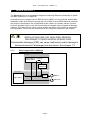
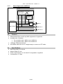
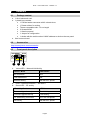
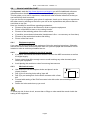
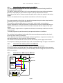
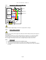
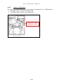
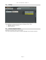
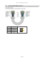
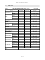
ALeX – User’s manual © - Revision 1.7 ALeX - User’s manual This symbol is intended to alert the user of important operating and maintenance (servicing) instructions in the literature provided with the equipment. This symbol is intended to alert the user of the presence of uninsulated dangerous voltage within the product’s enclosure that may present a risk of electric shock. 1 Caution Read Instruction: Read and understand all of the safety and operating instructions before using this equipment. Retain Instructions: The safety instructions should be kept for future reference. Follow Warnings: Follow all warnings and instructions marked on the equipment or in the user manual. Avoid Attachments: Do not use tools or attachments that are not recommended by Alyseum Company because they may be hazardous. ● ● ● Installation: Choose the installation location of your unit carefully. Avoid placing it in direct sunlight or close to a source of heat. Also avoid locations subject to vibrations and excessive dust, heat, cold or moisture. Power Source: This equipment should only be operated from the power source indicated on the product. When removing the wall-power plug from the wall outlet, never yank the cord. Servicing: Refer all servicing to qualified service personnel. There are no user-serviceable parts inside. To prevent the risk of shock, do not attempt to service this equipment yourself because opening or removing covers may expose you to dangerous voltage or other hazards. WARNING: TO PREVENT FIRE OR ELECTRIC SHOCK HAZARD, DO NOT EXPOSE THIS APPLIANCE TO RAIN OR MOISTURE. Page 1 ALeX – User’s manual © - Revision 1.7 2 1 2 3 4 5 6 7 Contents Caution .............................................................................................................................1 Contents ...........................................................................................................................2 What’s the ALeX ?............................................................................................................3 3.1.1 Block diagram with 1 MIDI Out .............................................................................3 3.1.2 Block diagram with 2 MIDI Out .............................................................................4 3.2 Features ...................................................................................................................4 3.3 Specifications ...........................................................................................................4 Hardware ..........................................................................................................................5 4.1 Package content.......................................................................................................5 4.2 Accessories ..............................................................................................................5 4.3 Front panel description .............................................................................................5 4.4 How to install the ALeX? ..........................................................................................6 4.4.1 Equipment opening...............................................................................................6 4.4.2 Choosing a location for the ALeX module ............................................................6 4.4.3 Mechanical works .................................................................................................6 4.4.4 How to find the solder points for the MIDI In.........................................................7 4.4.5 How to find the solder points for the MIDI Out......................................................7 4.4.6 Schematic for 1 MIDI In and 1 MIDI Out...............................................................7 4.4.7 Schematic for 1 MIDI In and 2 MIDI Outs .............................................................8 4.4.8 Power supply connection......................................................................................8 4.4.9 Powering up..........................................................................................................8 4.4.10 Jumper configuration ............................................................................................9 Software .........................................................................................................................10 5.1 CopperLan Manager...............................................................................................10 5.2 Merging function .....................................................................................................10 5.3 Establish connections .............................................................................................10 5.4 Settings...................................................................................................................11 5.5 Firmware Upgrade software ...................................................................................11 About ..............................................................................................................................12 6.1 Ethernet ..................................................................................................................12 6.1.1 Note about Wi-Fi use ..........................................................................................12 6.1.2 Tips for a efficient Ethernet Network...................................................................12 6.2 CopperLan..............................................................................................................12 Miscelleanous.................................................................................................................13 7.1 Disclaimer...............................................................................................................13 7.2 Maintenance ...........................................................................................................13 7.3 Static Electricity, ESD .............................................................................................13 7.3.1 Standard symbols for ESD advertising ...............................................................13 7.3.2 Some tips and precautions for ESD sensitive environment................................13 7.4 How to wiring the Ethernet cable ? .........................................................................14 7.5 Statement and Agency Compliance .......................................................................15 7.5.1 WEEE (for EU countries) ...................................................................................15 7.5.2 RoHS Compliance (for EU countries) ................................................................15 7.5.3 CE (for EU countries).........................................................................................15 7.6 Warranty and repair ................................................................................................15 7.7 MIDI Chart ..............................................................................................................16 Page 2 ALeX – User’s manual © - Revision 1.7 3 What’s the ALeX ? The Alyseum ALeX is an embedded computer board using Ethernet connectivity to retrofit any MIDI equipment to CopperLan. ALeX allows you to integrate up to 2 MIDI Out and 1 MIDI In for any products support MIDI Installation of the ALeX does not change the use of MIDI in the modified machine, although the module is interposed in the original MIDI stream, thanks to a hidden soft-thru function. ALeX are supplied ready to use, the actual linking is managed via the CopperLan Manager software. This freeware tool is also used to monitor the status of all CopperLan computers and equipment. The box can be controlled from any computer anywhere in the network. INSTALLATION ONLY BY QUALIFIED PERSON. DISCONNECT POWER DURING OPERATIONS. Electrostatic discharge (ESD) can cause malfunction and/or damage to electronic devices if discharged into the device. See chapter 7.3 3.1.1 Block diagram with 1 MIDI Out ALeX board Root Device MIDI Hybrid Locked link Invisible sub-device Host main board Opto MIDI In App. UART MIDI Out Page 3 ALeX – User’s manual © - Revision 1.7 3.1.2 Block diagram with 2 MIDI Out ALeX board Root Device MIDI Hybrid Locked link Invisible sub-device Host main board Opto App. UARTs MIDI In MIDI Out 1 MIDI Out 2 3.2 ● ● ● ● 3.3 ● ● ● ● Features Miniaturized PCB to retrofit any MIDI equipment to CopperLan . Available with 2 firmware. o For a machine with 1 MIDI In and 1 MIDI Out. o For a machine with 1 MIDI In and 2 MIDI Out. 100 Base-T Ethernet interface. Auto-MDIX allows the use of straight-trough or cross-over UTP cable. Specifications Size front panel: 23 x 36 mm Module Depth: 53 mm Power requirements: 5 to 18 Volts DC unregulated or regulated Consumption: 0,7 Watt Page 4 ALeX – User’s manual © - Revision 1.7 4 Hardware 4.1 Package content ● ● 1 ALeX electronic card 1 plastic bag contents : o 1 Female header connector with 6 colored wires o 1 Pattern sticker for cutting o Thermo retractable tube - 10 cm length o 2 Screws M3X8 o 1 Aluminum panel o 1 Jumper for configuration o 1 sticker with the serial number & MAC address to stick on the rear panel User’s manual card ● 4.2 Accessories http://www.alyseum.com/accessories 4.3 Front panel description ALYSEUM ALeX LK/ACT 1 1. 2 3 Yellow LED – Network Link/Activity LK/ACT Mode LED Pattern No connection OFF LINK established ON Network activity ON with OFF pulses 2. RJ45 – Ethernet connector – 100 Base-T 3. Green LED – CP activity CP activity Mode LED Pattern Firmware Upgrade ready Slow blinking Firmware Upgrade activity Fast blinking CP establishing connection OFF with ON pulses CP Activity ON with OFF pulses Page 5 ALeX – User’s manual © - Revision 1.7 4.4 How to install the ALeX? On Alyseum’s web site http://www.alyseum.com/support you will find additional reference information about installing the module as well as a list of equipment already upgraded. This list points you to user’s experience, manuals and other technical reference so that you can benefit from their know-how. If you are the first to upgrade a given piece of equipment, thank you to share your experience with other users by sending us the link to your site or the explanations and pictures that we could host on our site. Here is a checklist for an efficient upgrading explanation: ● Pictures of the screws to be removed in order to open the equipment ● Picture of the MIDI-in trace or wire cutting location ● Pictures of the soldering points of the various wires ● If possible, some related schematics (hand drawn is fine – we can carry on from there) ● Pictures of the mechanical location and drilling ● Picture of the final result 4.4.1 Equipment opening If you own the service manual of the equipment, follow the opening instructions. Otherwise, remove the screws with caution and place them on a piece of paper with annotation of their location in order to avoid any mistakes later on. 4.4.2 ● ● ● 4.4.3 ● ● ● ● ● Choosing a location for the ALeX module If possible, ensure that the location chosen is close to the MIDI connectors as well as the digital supply . Select a place that offers enough room to avoid touching any other electronic parts inside your equipment Avoid placing the module too close from strong heat sources Mechanical works TOP Use scissors to cut the template sticker and place it at the chosen location Drill (X) the 2 securing holes with a 3mm drill Drill (X) a pre-sawing hole for the RJ45 connector with a 3mm drill Proceed with sawing of the RJ45 connector hole with a wire saw according to the template Deburr the holes and clean up you work To avoid any risk of short circuit, ensure that no filings or other metal bits remain inside the casing of the equipment. Page 6 ALeX – User’s manual © - Revision 1.7 4.4.4 How to find the solder points for the MIDI In The MIDI standard mandates the use of an opto-isolator. This eases finding the MIDI-in signal that the ALeX requires. The MIDI-in signal going to the ALeX is to be connected to the output of the opto-isolator. Moreover, the majority of opto-isolators require a pull-up resistor at their output. Depending of the ease of access connect the green wire to either the output or the pull-up resistor. Refer to the datasheet of the opto-isolator manufacturer to find the output pin. For proper operation of the ALeX, the signal flow between the opto-isolator output and the processing unit of your equipment MUST be cut. This requires cutting a copper trace or, more rarely, a wire inside your equipment. Using a Ohmmeter to check the continuity, locate where a cut can be made that does not interfere with the pull-up resistor that must remain connected with the output of the optoisolator. When cutting a copper trace on a printed circuit board, be extremely careful as to not cut nearby traces. Proceed progressively until the continuity test proves that the cut is effective. The red wire is to be soldered on the side of the trace now disconnected from the circuit where the green cable is connected. This is likely the most delicate soldering job as there might be no components to solder the red cable besides the micro controller of the equipment. It is therefore recommended to connect the red wire directly to the copper on the board. This requires scratching the insulation layer until a reasonable length of copper is accessible. 4.4.5 How to find the solder points for the MIDI Out The best place is the resistor that leads to the pin 5 of the DIN connector. Connect the yellow wire to the side of the resistor opposed the one going to the connector. In installations with two MIDI outputs, proceed similarly with the orange wire and the second MIDI out connector. 4.4.6 Schematic for 1 MIDI In and 1 MIDI Out R App. UART App. Power ALYSEUM Opto MIDI In MIDI Out 5V to 18V GND or 0V ALeX LK/ACT Page 7 ALeX – User’s manual © - Revision 1.7 4.4.7 Schematic for 1 MIDI In and 2 MIDI Outs R Opto App. UARTs MIDI In MIDI Out 1 MIDI Out 2 App. Power ALYSEUM 5V to 18V GND or 0V ALeX LK/ACT Input & Output voltage ratings: 3.3V to 5V (1 logic) and 0V (0 logic) 4.4.8 Power supply connection Mistakes in the wiring of the supply may destroy the ALeX module and the power supply of your equipment Check with a Voltmeter the supply voltage inside the equipment. Try to locate the Digital positive between 5V minimum and 18 V DC maximum, and connect it the blue wire. Do not forget connecting the brown wire to a Digital 0V/ground point on the PCB. 4.4.9 ● ● ● Powering up Reread and check carefully all the installation steps. The LED should flash briefly as you switch on the supply of your equipment. Connecting an active network cable should make the Network LED blink according to the traffic. Page 8 ALeX – User’s manual © - Revision 1.7 4.4.10 Jumper configuration The jumper JP1 defines whether the Alex module is configured for 1 or 2 MIDI outputs. ● One MIDI output: no jumper at location JP4 ● Two MIDI outputs: jumper set at location JP4 1 MIDI Out= Open 2 MIDI Out= Short Page 9 ALeX – User’s manual © - Revision 1.7 5 Software 5.1 CopperLan Manager The CopperLan Manager is part of the CopperLan Package available cost free from the CopperLan website http://www.copperlan.org This application software provides 4 differents tabs for the management of a CopperLan network: 1. An Overview tab, displaying all machines and their current connections. 2. A Connect tab, to add/remove connections between device’s outputs and inputs. 3. An Edit tab, providing a universal way to edit parameters. 4. A Snapshot tab, to store network configuration and settings. 5.2 Merging function Connecting two or more sources to the same destination, realizes a merging functions. Beware that MIDI does not allow merging every type of message at any time. Merging two sysex messages may lead to unpredictable results. More informations on our application note: http://www.alyseum.com/download. 5.3 Establish connections It is possible to connect any source to any destination, as a whole virtual cable or according to message type. Establishing connections is done from the connection tab of the CopperLan Manager software application. To connect a whole virtual cable, select the appropriate source device and click on the MIDI connector icon. You complete the operation by selecting a destination. All messages appearing at the source will be transferred to the destination without any filtering or remapping. Instead of connecting a whole cable content, it is allowed to connect individually one or more message types according to the following split: 1. Note and Controller messages on a channel basis – these are channel messages Any of the 16 MIDI channels content can be linked separately 2. Clock messages (incl. clock control and song position messages) Any clock from any source can be connected to any destination. Note that MIDI destinations can only accept a single clock whereas CopperLan destinations can accept many. 3. Other messages (Sys) This selection covers all messages to the exception of messages in categories 1 and 2 here above. This linking is essentially used for SYS EX and MTC messages. It is meaningful to only connect sources and destinations of adequate messages type (e.g. Sys to Sys). However, it is allowed to connect any source channel to any destination channel, effectively realizing a channel remapping. More information on our application note: http://www.alyseum.com/downloads Page 10 ALeX – User’s manual © - Revision 1.7 5.4 Settings Three settings are accessed via the CopperLan Manager (Editor Tabs) 1. Restore originals connections. 2. Save destinations. 5.5 Firmware Upgrade software Upgrading the firmware is done via the network. This is done automatically through the CopperLan Manager via an internet connection. Page 11 ALeX – User’s manual © - Revision 1.7 6 6.1 About Ethernet Alyseum products rely on Ethernet to transport data; compared to other solutions (USB, IEEE1394, ...) Ethernet offers many advantages: ● Available on all computer platforms ● No real limit in cable length and node connections. ● Full Duplex. ● Very high bandwidth. ● Very low Latency. ● Frees the computer of the MIDI flow handling of USB/Firewire interfaces ● Embedded devices can work without any computer in the network ● Peer to peer capability. ● Full electrical isolation between machines, preventing audio hum due to ground loops. ● Low cost, ubiquitous, mature and reliable infrastructure. 6.1.1 Note about Wi-Fi use Using these products via Wi-Fi is possible but not guaranteed. Wireless transmissions are subject to perturbations that require data resending which implies unavoidable delays which are inconvenient for real-time musical purposes. This is why Alyseum only guarantees good performance when using wired network. 6.1.2 Tips for a efficient Ethernet Network The performance of an Ethernet network is always related to the weakest link. ● Use the WI-FI only for the web, Email, ... and the wired network of your computer for the CopperLan and audio streaming ● For large installations, use an additional network card in your computer to create a network dedicated only for CopperLan and audio streaming ● For large installations , preferably use Gbit Ethernet switches to guarantee a better data exchange ● Avoid Ethernet HUB as these create collisions in messages that could hamper the overall network performance 6.2 CopperLan CopperLan offers many advantages: ● Connectivity guaranteed with any hardware/Software supporting CopperLan. ● No IP addresses, thanks to an address abstraction layer. ● Protocol and networking system for command & control + streaming management. ● Self configuring & Plug and Play. ● Decentralized work distribution and storage – every CopperLan equipment incorporates its own server. CopperLan manages MIDI in a more powerful and flexible than any other technology available. The benefit of having its own dedicated protocol surpasses the afterthought solutions relying on TCP/UDP-IP in terms of speed and user-friendliness. Page 12 ALeX – User’s manual © - Revision 1.7 7 Miscelleanous 7.1 Disclaimer All rights reserved. Reproduction in whole or part of this document is prohibited without the express permission of Alyseum. © 2011 - 2015 Alyseum. The information and specifications described in this manual are subject to change without notice. Other products or brand names mentioned herein are trademarks of registered trademarks of their respective holders. 7.2 Maintenance Switch Off the power before maintenance. Do not attempt to clean the unit with chemical solvents (thinner, benzine or alcohol) as this might damage the finish. Use only a clean, dry cloth. 7.3 Static Electricity, ESD Electrostatic discharge (ESD) can cause malfunction and/or damage to electronic devices if discharged into the device. Even Alyseum products have built-in protections, ESD exists and might built up at levels that could harm your equipment. 7.3.1 Standard symbols for ESD advertising 7.3.2 Some tips and precautions for ESD sensitive environment ● ● ● ● ● ● ● Make sure to discharge any built-up static electricity from yourself and your device before touching or connecting one device to another Ground yourself by touching a earth grounded metal surface before handling your device and other equipments. For fixed installations, put the device in a grounded metallic rack. Ensure air relative humidity is minimum 60%. Install ESD specific prevention items, such as grounding mats. Reduce movement speed on handling or (dis)connecting devices Avoid carpet or other synthetic flooring. Page 13 ALeX – User’s manual © - Revision 1.7 7.4 How to wiring the Ethernet cable ? If you want to build your own Ethernet cable, dont worry, use CAT5 cable, RJ45 connectors and a crimping clamp. The maximum lenght for a single cables are 120 meters Pin Function 1 TX+ 2 TX- 3 RX- 6 RX+ 1 8 Page 14 ALeX – User’s manual © - Revision 1.7 7.5 7.5.1 Statement and Agency Compliance WEEE (for EU countries) Waste Electrical and Electronic Equipment (Directive 2002/96/EC) (applicable for E.U. Customers or others countries with separate collection systems) 1. This marking shown on the product or its literature, indicates that it should not be disposed with other household wastes at the end of its working life. 2. To prevent possible harm to the environment or human health from uncontrolled waste disposal, please separate this from other types of wastes and recycle it responsibly to promote the sustainable reuse of material resources. 3. Household users should contact either the retailer where they purchased this product, or their local government office, for details of where and how they can take this item for environmentally safe recycling. 7.5.2 RoHS Compliance (for EU countries) Alyseum products complies with the European Union restriction of the use of certain hazardous substances in electronics equipment, (RoHS directive 2002/95/EC) The RoHS directive prohibits the sale of certain electronic equipment containing some hazardous substances such as Mercury, Lead, Cadmium, Hexavalent chromium and certain Flame-retardants (PBB & PBDE) in the European Union. http://eur-lex.europa.eu/LexUriServ/LexUriServ.do?uri=CELEX:32002L0095:EN:HTML 7.5.3 CE (for EU countries) Alyseum products complies with the requirements of European Directive 89/336/EC. 7.6 Warranty and repair Alyseum warrants to you, the original purchaser, that each of its products will be free from defects in materials and workmanship for a period of two years from the date of purchase. This warranty does not apply to any products which have been repaired or altered by other than repair personnel authorized by Alyseum, or which have been subject to ESD, moisture, abuse, accident or improper installation and using. Alyseum assumes no liability as a consequence of such events under the terms of this Warranty. Please consult your shop for more details. Page 15 ALeX – User’s manual © - Revision 1.7 7.7 MIDI Chart ALeX MIDI IMPLEMENTATION CHART ver.1.0. Function 2011-03-30 Transmitted Recognized Remarks 1-16 1-16 pass-through Changed -- -- via network mapping Default -- -- not applicable Messages X X pass-through Altered -- -- not applicable 0-127 0-127 pass-through X X pass-through Keys X X pass-through Channels X X pass-through Ptch Bend X X pass-through Control Change X X pass-through Prog. Change True# X X pass-through System exclusive X X pass-through Song Position X X pass-through Song Select X X pass-through Tune Request X X pass-through Clock X X pass-through Commands X X pass-through Local On/Off X X pass-through All Notes Off X X pass-through Active Sensing O X Via CopperLan System Reset O O Default Basic Channel Mode Note Number Velocity After Touch System Common System Realtime Aux Messages Notes Page 16