1
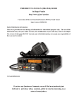
19-07-1998
Tandy HF HTX-100 review
Thank you for your interest. The Tandy HTX-100 Amateur Radio Transceiver is a close
cousin of the Uniden HR-2510 (Listed as the Amateur Radio Model HR-2510 (UT550B). HTX for Ham Tranceiver, HR for Ham Radio, UT for Uniden Transceiver. We
can assume the A suffix for the HTX-100.)
My first HF radio as a Novice was a HTX-100, so there was always a lingering question
as if the Tandy model was capable of similar capabilities. I had spent many hours
examining the mini-schematic diagram at the end of the manual.
This information was derived from the buying of a HR-2510 service manual at the local
hamfest. When I examined the PLL schematic, I realized that I was looking at a prior
generation of the same PLL circuit. It helped to complete the purchase.
The Uniden HR-2510 microcontroller u1201 is a 46 pin Dual Inline Package. On the
diagnostic voltage table for the microcontroller , there are two pins labeled
(34)AMATEUR and (35)GND aside of each other. They are pulled to GROUND. #34
will open TX/RX from 26.000 Mhz to 28.000 Mhz,#35 will open 29.7 to 30 Mhz.
On the schematic for the HTX-100, there are similar pins 28 and 29 on U1208 pulled up
by a resistor pack to Vcc.
The Tandy model microcontroller is a surface-mount device and the pins on the chips
don't bend: they SNAP. The steel used on the pins are quite different. Do not attempt to
physically pull on the pins of the package.
(This does not stop the fact that one HTX-100 bit the Big One under the Knife under the
hands of a Electronics Technician. This is one heck of a way to learn about how to not
handle Surface Mounted Technology.)
Percy KF2AT wrote the mods for the HTX-100. Sorry for the week's delay but I had jury
duty. Use common sense, a grounded soldering iron, and enjoy the mods.
19-07-1998
Extended Frequency Coverage from 26.000 Mhz to 30.000 Mhz
Remove bottom cover. With the radio upside down and display facing you remove the
synthesizer board with the four screws, this is near the front of the radio. This gives
access to the small board underneath with the surface mount components on it. Locate the
processor chip IC401 (UC-1208).Locate pins 28 and 29 which are on the right hand side
of the chip and are 4th and 5th from the top. Note they are bridged with solder.
CAREFULLY cut the copper track NEXT to the pins. DO NOT attempt to unsolder the
two pins form the board and use a GROUNDED soldering iron. Locate the two rows of
connector pins above the chip.
On the bottom row locate the last pin on the right. Verify with a VOM that this pin has +
five volts. Solder a 10k (1/4 w) resistor between this pin and pins 28 and 29 on IC401.
The synthesizer will now tune from 26.00 Mhz to 30 Mhz.
19-07-1998
Simple RF Wattage Enhancement to HTX-100 of 35 Watts
With the radio in the same position as before, locate VR5 in the top left hand corner. This
is the RF high power preset.
Lift and bend the wiper so that is is permanently disconnected form the track. Solder a
47k resistor (1/4 watt) between the wiper and the left hand side of the track.
This should increase the RF power output to around 35 watts but you will now not be
able to trim the power output. The Low power trim will function as before.
* Simple RF Wattage Enhancement to 35 Watts
* Enhancement of Microphone Frequency Response
19-07-1998
Enhancement of Microphone Frequency Response
1. To increase average depth of modulation
Remove top cover of the radio and with the display facing you and the radio upright
locate IC3 (NJM4558S/JRC9A31) near the bottom right hand corner of the main large
board.
Just to the right of this IC locate c75 (56 pf) and remove it. This will increase the gain of
the microphone Preamp considerably but without overmodulation. If you find the
compression excessive(i.e. background noise) open the microphone and insert a 470 ohm
resistor between the hot side of the mic insert and the input (white lead).
This is reduce the gain somewhat but will still give you much increased "talk power"
(percy's words, not mine. Adam).
2. To increase audio response in the high mids
This simple mod will recrease the audio response in TX in the 2 to 2.7 khz region giving
higher articulation and move intelligibility under weak signal conditions.
Locate IC3 as before on the large main board and the radio positioned as before. Locate a
5.6k and a 4.7k resistor just below IC3.
Solder a 0.015 mf (16v) capacitor between the left side of the 4.7k to the right side of the
5.6k resistor.
These two mods work together to give improved readability on SSB under DX
conditions.
23-08-1998
HTX-100 error in the Enhancement
From: "The Poustie's" [email protected]
I recently have been working on a htx100 with the aim of enhancing it's abilities. I have
two points for you today. First there is an error in the "Enhancement of frequency
response" text. The capacitor described as c75 is a 560 pf, not 56 pf as published.
Secondly, I would like to contribute a new mod for this radio.
Conversion to lower sideband.
* Remove power, antenna, and microphone.
* Remove upper and lower covers.
* Remove PLL board.
* Locate L12. Beside L12 is a 12 pf capacitor, replace this with a 47 pf.
* Adjust L12 for best clarification on known signal source.
* Reassemble radio.
You now have lower sideband and cw.
28-03-1999
Unlock the RIT on the HTX-100 XIT-IT
I've had a lot of fun working DX from my car with this rig. It is one of the easiest to
modify, if you want to unlock the RIT. One of the major drawbacks with a rig of this
class (HR-2510,HR-2600, HTX-100) is the tuning. There are usually 4 step sizes used
when tuning to the desired frequency. (500 kHz, 10 kHz, 1 kHz and 100 cycles). The 500
kHz step is rarely used. Its main purpose is to move you from one part of 10 meters to
another. For example, if you are in the CW portion of the band and want to move to the
SSB end, this switch is handy.
The 10 kHz step tuning can be used when looking for contacts but you skip over most of
the band. The 1 kHz step isn't too bad, but if the other station is 1/2 kHz off frequency,
you'll have to switch over to the 1 hundred cycle tuning. Even then, the station may be 50
cycles off from you. I always found myself using the 10kHz step to find a section of the
band with activity, then switching to the 1kHz step to pick out a 'loud one' then switching
again to the 100 cycle tuning to fine tune the person in. Often times I still could not get
the station in just right, and there just isn't any other way to get any closer to their
frequency! Sure, you can use the rig's RIT contol to tune your receiver right on, but then
your transmit frequency is still off a bit since it doesn't move with the RIT control!
What's the answer? A simple modification to allow the transmit frequency to move in
sync with the receiver frequency when using the RIT control. This mod takes only a few
minutes, is reversable (in case you change your mind later) and really makes the radio a
pleasure to use afterwards.
Parts:
There are only 2 parts to this conversion. You'll need a 6 inch piece of wire and a 10k
variable resistor. Any 10k pot should work fine.
Preparing The Radio:
To begin the conversion, first place the radio on a flat SOFT surface (the cases of these
rigs seem to scratch easily) with the speaker side down, and place the rig so the front is
facing you. Remove the top 4 cover screws and the top cover. Locate the radio's lamp
light, and follow the white leads down to the green circuit board. Notice that one of the
lamp's leads is connected to a point on the board marked as +8. Now look on the circuit
board to the right of the +8 point. You should see a white jumper plug. In front of this
and slightly to the left is a printed circuit board trace line. It is a straight line with a solder
point on each end. If you have a volt meter take a voltage reading from this trace against
the chassis ground. It should read near 7 volts. Mark down this number.
The Conversion:
Next, disconnect the power from the radio. Take the 10k variable resistor and solder the
center tap lead of the resistor to the board at the +8 solder point. Next take the 6 inch wire
and solder it to either of the two remaining leads of the variable resistor. Use a sharp tool
to break the straight line trace that you had just found. Cut it in the middle of the line if
possible. Then solder the free end of the 6 inch wire to the end of the trace closest to the
front of the radio. The existing end solder point works nicely for this. This trace line
originally provided voltage only during receive. Since the 8 volt source that we are now
tapped into is there during both receive and transmit, the control will change frequency in
both cases now.
Testing Your Work:
Connect the antenna and power but do not replace the cover yet. Now you have to reset
the radio back on frequency. To do this, you can use a frequency counter, or a local ham.
Set the RIT (now RIT/XIT) to the center OFF position and adjust the 10k resistor to set
the radio on the correct frequency. Have your ham friend transmit on a pre-determined
frequency while you set the resistor to tune them in. Another method would be to use the
voltage reading that you took earlier, you can just check the center tap of the resistor now
and set the pot to the original voltage and you will be close to the correct frequency. Once
back on frequency replace the cover, screws, antenna and power. At this point, let me
inject a word of warning, your frequency display WILL NOT CHANGE as you use this
new RIT/XIT. So be careful around the band edges, don't get too close or you may
actually be out of band!
Now You're ready to see how much easier the rig is to operate. With the RIT unlocked, I
generally just leave the step size set to the 1kHz position, tune close to a "loud one'" and
then just use the RIT/XIT for the final touch up. You get about 1 1/2 kHzs on each side of
the control's center. It's great! Have fun and I'll see you on 10 meters!
25-01-2000
Uniden/Realistic HTX 100 Selectable Sideband Mod.
Conversion of the HTX-100 to USB/LSB.
Here is a cheap and easy conversion to selectable sideband operation. With this mod, the
CW function is lost, but with a few more parts (1coil can approx 10 mh, 1 22pf cap, 1
470 mh choke) on a small board it could easily be restored if it is wanted. The basic
theory of this modification is that the CW portion of the carrier oscillator tuning circuit is
padded and rerouted into the USB circuit via a small switch, to provide LSB.
Solder a 27 to 35 pf ceramic capacitor across the pins of C120, the tiny 22 pf ceramic that
is next to the cw coil can L13(do this from the bottom of the board) Now lift the switch
side ends of r81 and r115, and connect them with some fine wire them to a spdt switch.(I
use the rx/tx switch, after jumpering it to the rx position and cutting the traces.), You
want the ends of the resistors that connect to the transistors Q14 and Q19, not the ends
that connect to the chokes L11 and L9.
Take the center lead from the switch back to the point on the board where the USB
resistor R81 was lifted from.
So the rx/tx switch is now your sideband select switch. You must manually offset the
reference oscillator (VFO) by the if filter bandwidth (-2.5 khz), so if you want to be on cb
channel 38 lsb, then you tune to 27.3825. Tune in a known good signal on the lower
sideband, (xx.xx25 not xx.xx50!) and align the rig's LSB carrier oscillator circuit by
adjusting L13. Gently! The core is fragile. If you crack it you can save it by removing the
can from the board and unscrewing the core from the bottom. Invert and reinstall core,
reinstall can. (Try to avoid this)
Revision B: replace L13 with a 10 mh fixed inductor, and C120 with a 35 p or 50 pf
variable. Tune using the variable capacitor. This method is better for those of us who
crack inductor cores.
Lastly, if operation below 27.5 MHz is desired, some further adjustment is in order, as
this rig's power output falls off rapidly below that point. The broadbanding adjustment
commonly used on the HR2510 will not work on this radio, but this does. With top cover
off, observe the two filters marked DO NOT ADJ. The right hand one controls the input
to the final amplifier. Remove the sticker, and adjust the rearmost screw anticlockwise
about 1 turn.
Check power output at 26.0 MHz before and after. You will see the power output go up
from about 5 watts to 25 or 35 quite quickly. Note that now the rig will now have poor
power from 29.00 MHz and up.
Note that this filter adjustment may increase harmonic or out of band emissions; I have
not checked this, but have not experienced any TVI or performance problems with the
rigs I have converted to date.
In the event of an alignment problem, have it tuned up as if it were an SSB only Uniden
HR2510, which is what it basically is. Enjoy, use at own risk. Note that transmissions out
of band may be illegal in your area. :-)