1
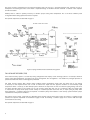
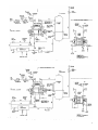
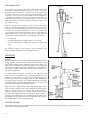
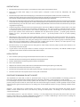
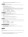
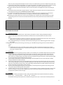
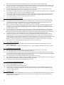
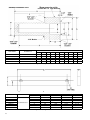
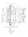
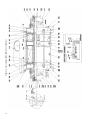
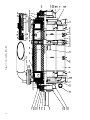
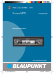
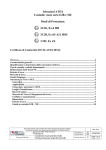
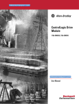
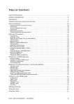
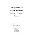
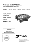
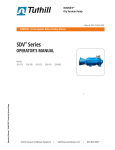
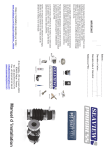
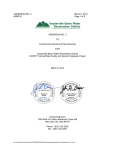
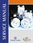
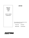
Manual 4804-2
KINNEY® KLRC™ SERIES
Liquid Ring Vacuum Pumps
Models
KLRC-40
KLRC-75
KLRC-100
KLRC-300
KLRC-525
KLRC-526
KLRC-125
KLRC-950
KLRC-200
KLRC-951
INSTALLATION
OPERATION
MAINTENANCE
REPAIR
MANUAL
WARNING
DO NOT OPERATE
BEFORE READING MANUAL
08/2012
4840 West Kearney Street, P. O. Box 2877
Springfield, Missouri USA 65801-2877
Tel 417 865-8715 800 825-6937 Fax 417 865-2950
www.tuthillvacuumblower.com
WARNING
CAUTION
DO NOT VALVE OR RESTRICT PUMP
DISCHARGE OPENING.
USE OIL MIST ELIMINATOR WHEN
OPERATING PUMP, ENSURE ADEQUATE
VENTILATION WHEN DISCHARGING INDOORS
DO NOT OPERATE
WITHOUT BELT
GUARD
REFER TO MANUAL SAFETY INSTRUCTIONS.
NOTICE
The above safety instruction tags were permanently affixed to your pump prior to shipment.
Do not remove, paint over or obscure in any manner.
Failure to heed these warnings could result in serious bodily injury
to the personnel operating and maintaining this equipment.
SAFETY PRECAUTIONS FOR LIQUID RING PUMPS
Please read the following safety information on this page before operating your vacuum pump.
•
Please read the following safety information on this page before operating your vacuum pump.
•
Do not operate the pump without the coupling or belt guard properly attached. Disconnect the pump motor from the electrical
supply at the main disconnect before removing the coupling or belt guard . Replace the coupling or belt guard before
reconnecting the power supply to the pump motor. Operating the pump without the coupling or belt guard properly installed
exposes personnel in the vicinity of the pump to risk from rotating drive components.
•
CAUTION: Do not operate the pump with oxygen-enriched gas in the suction line, unless the pump has been properly
cleaned, inspected and certified to be free of hydrocarbon presence and prepared with an inert fluid suitable for the
application.
•
Oxygen-enriched gas is defined as gas of which the constituents include by volume (mol. %) an amount of oxygen greater than
that of standard atmospheric air (typically 20-21% by volume).
•
If the oxygen content in the gas stream exceeds the proportions found in standard atmospheric air, then it is considered an
oxygen-enriched gas and standard mineral oil, synthetic hydrocarbon oil or other non-inert fluids should not be used.
•
WARNING: Pumping oxygen-enriched gases with mineral oil, synthetic hydrocarbon oil or other non-inert fluids can
cause fire or explosion in the pump, resulting in damage or serious bodily injury or death.
•
Take precautions to avoid prolonged or excessive exposure to oil mist or process materials emanating from the discharge of
the pump.
•
Do not allow the pump to discharge into a closed, or inadequately ventilated room. Laws and ordinances may pertain to
your local area regarding discharge of vapor to atmosphere. Check local laws and ordinances prior to operation of the pump
with discharge to outside atmosphere. Venting of the discharge of an oil mist eliminator to outside atmosphere is highly
recommended.
•
Do not restrict the pump discharge in any way, or place valves in the discharge line. The vacuum pump is a compressor and
will generate high pressures without stalling the motor when operated at low suction pressures. Excessive pressure could
cause pump damage or serious bodily injury.
•
Disconnect the pump motor from the electrical supply at the main disconnect before disassembling or servicing the pump.
Make sure pump is completely reassembled, the coupling or belt guard is properly installed, and that all fill and drain valves are
installed and closed before reconnecting the power supply. Accidental starting or operation of the pump while maintenance
is in progress could cause pump damage or serious bodily injury.
•
Lift pump only by strapping the crossover pipe. DO NOT lift equipment attached to pump by the pump lifting lugs.
•
Do not touch hot surfaces on the pump. In normal operation at low pressures, surface temperatures will not normally exceed
180° F (82° C). Prolonged operation at 200 Torr (267 mbar a) may cause surface temperatures as high as 220° F (104° C)
2
TABLE OF CONTENTS
SECTION
INTRODUCTION
PAGE
4
MODELS COVERED BY THIS MANUAL
4
NAMEPLATE DATA
4
SUITABLE APPLICATIONS
4
AVOID DAMAGE TO THE PUMP
4
SPECIFICATION TABLE (TABLE 1)
5
THEORY OF OPERATION
5
PROPERTIES OF SEALANTS
5
SEALANT TEMPERATURE
6
INSTALLATION
6
GENERAL
6
DIRECT COUPLED DRIVE
6
V-BELT DRIVE
6
SEALANT RECOVERY SYSTEMS
7
ONCE-THROUGH RECOVERY
7
PARTIAL SEALANT RECOVERY (PSR)
8
SEALANT PIPING
10
SEALANT FLOW CONTROL
10
COOLING PIPING FOR MECHANICAL SEALS
10
MANIFOLD PIPING
11
ELECTRICAL CONNECTIONS
11
SYSTEM COMPONENTS
11
INLET AIR EJECTORS
12
OPERATION
12
STARTING THE PUMP
12
PRESTART CHECKS
13
INITIAL START UP
13
PROCEDURE FOR MINIMUM SEALANT FLOW RATE
13
STOPPING THE PUMP
14
MAINTENANCE
14
GENERAL
14
SHAFT BEARINGS
14
SCALE OR RUST ACCUMULATION
15
MECHANICAL SHAFT SEALS
15
PREPARATION FOR STORAGE
15
SPARE PARTS
15
DISASSEMBLY
15
GENERAL
15
DISASSEMBLY PROCEDURE
15
REASSEMBLY
16
GENERAL
16
REASSEMBLY PROCEDURE
ASSEMBLY DRAWINGS & PARTS LISTS
WARRANTY – VACUUM PRODUCTS
17
23-31
32
3
INTRODUCTION
CONGRATULATIONS on your purchase of a new KINNEY® KLRC™ Liquid Ring Vacuum Pump from Tuthill Vacuum & Blower
Systems. Please examine the pump for shipping damage, and if any damage is found, report it immediately to the carrier. If the
pump is to be installed at a later date make sure it is stored in a clean, dry location and rotated regularly. Make sure covers are kept
on all openings. If the pump is stored outdoors be sure to protect it from weather and corrosion.
KINNEY KLRC vacuum pumps are built to exacting standards and if properly installed and maintained will provide many years of
reliable service. We urge you to take time to read and follow every step of these instructions when installing and maintaining your
pump. We have tried to make these instructions as straightforward as possible. We realize getting any new piece of equipment up
and running in as little time as possible is imperative to production.
WARNING: Serious injury can result from operating or repairing this machine without first reading the service manual and
taking adequate safety precautions.
IMPORTANT: Record the pump model and serial numbers in the OPERATING DATA form on the last page of this manual. You
will save time and expense by including this reference identification on any replacement part orders, or if you require service
or application assistance.
MODELS COVERED BY THIS MANUAL
This manual contains installation, operation, and maintenance procedures for KLRC-40K to KLRC-951K. The nameplate on the
pumps provides a letter coding for pump material and shaft seal type in the suffix following the KLRC model number.
NAMEPLATE DATA
The first letter designates the standard materials of construction:
B Cast Iron casing, bronze impellers, 316 stainless steel shaft and steel trim
F Cast iron casing with stainless steel 316L impellers and 316 Shaft and steel trim
C All stainless steel 316L pump, except for the outboard ball bearings, bearing end caps, and steel trim
The second suffix letter designates the standard type of shaft seal:
A John Crane Type 21 seal — Carbon/Ceramic/Viton
D Flow Serve RO Dura Seal — Carbon/Durchrome/Viton
L PTFE encapsulated Viton O-Rings
DD Flow Serve Double RO Dura Seal
Consult factory for alternate seal configurations. When the nameplate model designation is followed by the letters -HT the pump
has an operating temperature limit of 220°F. Inquiries should be referred to Tuthill Vacuum & Blower Systems, referencing model
and serial number of the pump.
SUITABLE APPLICATIONS
Kinney Liquid Ring Vacuum Pumps (KLRC) are reliable non-pulsating pumps. KLRC pumps are two stage configuration, suitable
for operation down to 30 Torr absolute (approximately 29 inches Hg. vacuum reference 30 inch barometer), when sealed with 60°F
water.
Standard pumps with stainless steel impellers (designated with material codes F or C) are suitable for operation with sealant
temperatures up to 160° F. Bronze impeller pumps (designated with material code B) and pumps with HT following the Model
designation on the nameplate are suitable for operation with sealant temperatures up to 220°F. Consult Tuthill Vacuum & Blower
Systems for applications requiring operations above 220°F.
AVOID DAMAGE TO THE PUMP
•
Unpack the pump carefully and handle only by methods that will not damage or misalign the pump.
•
Do not run the pump dry. Make sure sealant is piped to both seals; see Figures 2 through 5.
•
Do not allow sealant in the pump to freeze.
•
Do not place any valves or restrictions in the discharge line.
•
If the pump and motor are mounted on a base, the unit should only be lifted from the base or by attaching to the base. Lifting
the unit by attaching to the pump or motor could disturb the alignment. The crossover manifolding on the KLRC-series pumps
should never be used as an attaching area for lifting.
4
SPECIFICATION TABLE (TABLE 1)
UNIT
KLRC
40
KLRC
75
KLRC
100
KLRC
125
KLRC
200
KLRC
300
KLRC
525
KLRC
526
KLRC
950
KLRC
951
Speed
RPM
1750
1750
1750
1750
1750
1750
1750
1450
1150
860
Drive
Type
Direct
Direct
Direct
Direct
Direct
Direct
Direct
Belt
Direct
Belt
Standard motor
HP
kW
GPM
L/min
5
3.8
5
19
5
3.8
5
19
7.5
5.6
6
23
10
7.6
7
26
15
11.4
8
30
25
19
12
45
50
38
18
70
40
30.4
18
70
100
74.6
26
98
75
55.9
26
98
GPM
L/min
3
11
3
11
4
15
4
15
4
23
6
30
9
45
9
45
13
49
13
49
US Gal
Liters
4.6
18
5
19
6
23
6.3
24
7.5
28
9
34
24
91
24
91
—
—
GPM
L/min
5
19
5
19
7
27
10
28
15
57
25
95
50
190
50
190
52
197
52
197
NPT
1/2”
1/2”
3/4”
3/4”
1”
1”
1 1/4”
1 1/4”
1 1/2”
1 1/2”
1 1/2”
1 1/2”
1 1/2”
1 1/2”
2”
2”
3”
3”
4”
4”
22.6
573
12.6
321
11.9
302
6.5
165
155
70
24.1
613
12.6
321
11.9
302
6.5
165
200
91
25.8
654
16
406
12.8
324
6.9
175
230
104
28.1
713
16
406
12.8
324
6.9
175
255
116
29.7
754
19.1
486
16.9
429
8.3
210
360
163
33.6
852
19.1
486
16.9
429
8.3
210
405
184
41
1041
23.5
597
18.9
479
9.8
249
800
363
41
1041
23.5
597
18.9
479
9.8
249
800
363
56.5
1435
30.56
776
25.32
643
12.59
320
1590
721
56.5
1435
30.56
776
25.32
643
12.59
320
1590
721
Sealant liquid required
(at 60° F w/ no sealant recovery)
Sealant liquid required
(at 60° F w/ partial sealant recovery)
Liquid required to fill a
Full Sealant Recovery (FSR) System
Cooling fluid at 60° F
required for HX*
Sealant Liquid Connections
**ANSI
150
Class
in
mm
in
mm
in
mm
in
mm
Lbs.
kg
Inlet/Outlet Flange
Overall Length
Overall Height
Width
Shaft Height
Weight, Net Pump only
* The HX cooling fluid flow rates are based on sealant fluid entering the HX at 80° F and exiting at 65°F. Cooler or warmer fluid than 60° will effect the flow
rate.
** (ANSI) American National Standards Institute
THEORY OF OPERATION
When the pump is in operation, a continuous flow of sealant liquid is entering the pump and forms a seal between the impeller
and casing (see Figure 1). The impeller is off-set above center of the
pump casing and as the impeller rotates, pumping action begins in the
space between the impeller and casing by filling and emptying similar to
a reciprocating compressor (engine). Gas inlet and discharge ports are
Gas Inlet
Liquid & Gas Out
positioned so as to draw gas into the cavity inside the liquid sealed ring
during the expansion segment, and discharge gas along with some liquid
during the compression segment.
The discharged liquid can be recovered and recirculated through the use
of a gas/liquid separator.
An attenuation valve is provided to drain sealant from the pump before
starting and to bleed air into the purnp to prevent cavitation, which occurs,
when the pressure is low and the airflow is minimal. To additionally protect
against cavitation an optional air bleed valve and/or vacuum relief valve can
be installed in the suction line.
Water is normally used as a liquid seal, but may be unsuitable for some
pump applications, Tuthill Vacuum & Blower Systems should be consulted
before changing to a different liquid in the pump.
Impeller
Casing
Liquid
Ring
Gas Entering
Cavity within
Liquid Ring
Gas Leaving
Cavity within
Liquid Ring
Seal Liquid Inlet
Figure 1. Cross Section Liquid Ring Pump
PROPERTIES OF SEALANTS
Water is the most commonly used sealant in liquid ring vacuum pumps. Other fluids may be used to obtain process compatibility.
In these applications special consideration should be given to the properties of the sealant, which may affect pump performance.
Some of the properties of sealant which should be considered, are:
• Specific Gravity
• Specific Heat
• Viscosity
• Vapor Pressure
5
Additionally the solubility of process gas in the sealant can be of significance and should be
evaluated especially if the partial or full recovery system is used. When water is the sealant its
chemical content should be evaluated since certain conditions will affect the service life of the
pump. Generally if water is suitable to drink it is suitable for pump use. Hardness greater than
500 PPM will result in internal plating and fouling of pump parts. Service with hardness of less
than 500 PPM depends upon operating temperature and the nature of the mineral deposit.
Naturally occurring well water with organic acid of pH-5 or higher is generally suitable, however
pH of 7 or higher is preferred. Chemically treated water with sulfur content requires pH-7 or
more. Water, which has a pH less than 5 should be treated or the pump should have special
materials of construction. If internal scaling affects performance, a water treatment specialist
should be consulted. Tuthill Vacuum & Blower Systems recommends that sealants and sealant
systems be carefully evaluated and we invite you to discuss them with your Tuthill Vacuum &
Blower Systems Sales Professional or our Application Engineers.
SEALANT TEMPERATURE
The rated capacity (ACFM) of a pump is based upon the use of incoming seal water at 60c F.
Seal water temperature affects the pump capacity. Table 2 provides data which when applied
to the below formula will give the pumping capacity on dry air at water temperature other than
60 °F. To calculate pumping capacity (ACFM) or to approximate the capacity when using water
at other than 60 ° F the following formulas apply.
Sa= S60 × ( P1 - Pc ) / ( P1 - 13.3 )
Where: Sa = S60 =
P1 =
Pc =
VAPOR PRESSURE
OF WATER (Table 2)
WATER
SEALANT
TEMPERATURE °F
VAPOR
PRESSURE
TORR
50
52
54
56
58
60
62
64
66
68
70
72
74
76
78
80
9.2
9.9
10.7
11.5
12.3
13.3
14.2
15.3
16.4
17.5
18.8
20.1
21.5
22.9
24.5
26.2
Actual capacity in ACFM, at P1
Pump capacity with 60°F sealant at P1 (This data is shown on Data Sheet 4703.)
Inlet pressure in. Torr
Vapor pressure of sealant at actual sealant temperature
INSTALLATION
GENERAL
Pumps are partially filled with a water-soluble rust inhibitor prior to shipment. This solution should be drained or flushed from the
pump. Drain pump by removing drain plugs.
Liquid ring pump units with pump and motor on a common base, can be located on any flat and level flooring suitable for their
weight. The pumps are almost vibration free and foundation bolting is not normally required. Using elastomer machine mounting
pads (Vibration Controls) is helpful to eliminate minor floor vibrations. When the base must be bolted to the floor, it should be
shimmed as necessary to avoid any base distortion.
DIRECT COUPLED DRIVE
Pumps shipped with the pump and motor directly coupled and mounted on a common base have been aligned prior to shipment
and normally no further alignment is necessary. However, alignment should be checked and adjustments made if necessary prior to
starting unit. Generally, when installing flexible couplings, the two shafts must be aligned to within .020 of an inch (maximum), and
the coupling halves must be positioned on the shafts to be parallel to each other within .030 of an inch (maximum) when measured
around the periphery of the coupling halves.
V-BELT DRIVE
Before attempting to tension any V-belt drive it is imperative that the sheaves be properly aligned. V-belts should be replaced in sets
and the sheaves should be positioned so as to allow the belts to be placed in the grooves without rolling them onto the sheaves.
The following tensioning steps can be safely followed for all belt types:
1.
2.
3.
With belts properly in their grooves, adjust the sheaves until all slack has been taken up.
Start the drive and continue to tension the V-belt(s) until only a slight bow on the slack side of the drive appears while operating
under load conditions.
After 24 to 48 hours of operation the belts will seat themselves in the sheave grooves. Further tensioning may be necessary as
described in Step 2.
Slipping (squealing) at start up is often evidence of insufficient tensioning. Belt dressing should not be used on V-belts. Sheaves
6
and V- belts should remain free of oil and grease. Tension should be removed from belts if the drive is to be inactive for an extended
period of time.
WARNING: The belt guard or coupling guard must be properly secured in place at all times while the pump is running.
SEALANT RECOVERY SYSTEMS
Figures 2 through 5 illustrate sealant configurations:
•
Once-Through (Fig. 2)
•
Partial Recovery (Fig. 3)
•
Full Recovery with Circulating Pump (Fig. 4)
•
Full Recovery without Circulating (Fig. 5).
CAUTION: Do not run the pump dry
ONCE-THROUGH RECOVERY
This arrangement takes water directly from the water supply, through the pump and discharges it directly through a gas/liquid
separator tank to an approved drain. This arrangement is most common on small pumps, in installations where water conservation
is not a factor, or where contamination of sealant is not a factor. Optional valving arrangement is designed to conserve sealant flow
and power and when pump is operating at high pressure (low vacuum).
The optional components are described on page 17.
KLRC 100 TO 950
KLRC 40 AND 75 ONLY
Figure 2. Piping Schematic Once - Through Recovery System
PARTIAL SEALANT RECOVERY (PSR)
7
The partial recovery arrangement has the pump discharging water and gas into a gas/liquid separator tank, releasing the gas to
atmosphere and retaining the water. Some water is disposed through an overflow and the remainder is retained in the separator
tank for recirculation.
Makeup water is added in quantity necessary to maintain proper sealing water temperature. This is the most commonly used
arrangement where sealing liquid conservation is required.
The optional components are described on page 11.
KLRC 100 TO 950
KLRC 40 AND 75 ONLY
Figure 3. Piping Schematic Partial Sealant Recovery System
FULL SEALANT RECOVERY (FSR)
A full sealant recovery system is a closed loop sealing configuration that employs a heat exchanger, (water or air-cooled) to maintain
proper sealing fluid temperature. See Figure 4 for piping arrangement. This arrangement is not suitable for prolonged operation at
pressure above 400 Torr unless a circulating pump is installed.
Full liquid recovery systems often operate under conditions where condensation would cause the liquid level to rise making
it necessary to drain liquid from the unit in order to maintain the liquid level. The opposite condition can exist whereby liquid
evaporation makes it necessary to add makeup liquid to maintain the liquid level. If there are extensive piping fittings and valves
and other restrictive devices in the sealant line on a full recovery system that does not use a circulation pump, the sealant liquid
is induced into the pump under pump suction entirely. For sustained operation above 400 Torr, on rapid cycling of pump down
from atmosphere, a circulation pump may be required. A circulation pump, when added to a full recovery system maintains proper
sealant flow at all inlet pressure conditions.
The pressure on the sealant gauge will vary depending upon the inlet pressure, from several inches of vacuum to a slightly positive
pressure. The optional components are described on pages 14 and 15. Normally, a common supply line is used for both seal liquid
and mechanical seal cooling.
The optional components are described on page 11.
8
KLRC 100 TO 950
KLRC 40 AND 75 ONLY
Figure 4. Piping Schematic Full Sealant Recovery System with Circulating Pump
KLRC 100 TO 525
KLRC 40 AND 75 ONLY
SEALANT PIPING
Figure 5. Piping Schematic Full Sealant Recovery System, Without Circulating Pump
9
See the Specification Table on page 5 for size of connections. Figures 2, 3, 4, and 5 show the connection locations for suction and
discharge gas, sealant water and shaft seal cooling water of different pump models. Note that connections are different for KLRC-40
and -75 compared to the KLRC-I00 to -950. Also shown are the valves and gauges as they should generally be located for any of the
piping arrangements. Piping must be no smaller than the pump connection and must be aligned, and may have to be supported,
so as not to place a strain on the pump.
Normally it is not necessary to drain a pump to shaft level prior to starting, provided that the incoming sealant flow was stopped
simultaneously with stopping the pump during the last shutdown. An automatic solenoid valve (normally closed) is convenient for
this use. The pump may be manually drained to shaft level by use of the attenuation valve.
As the pump creates its own vacuum it will draw in the required amount of sealant, so that the sealant need not be under pressure
when pumping below 400 Torr. From 400 to 760 Torr, if the pump should operate for an extended period of time, a minimum of 7
PSI pressurized sealant would be required. The Specification Table on Page 5 provides the flow rates of water at 60 °F required for
standard pumps at standard conditions. Recommended flow rates should provide an overall temperature rise of 10° F in a watersealed pump.
Sealant flow rates and temperatures represent important considerations because of their effect on the heat balance of the pump. If
the pump must operate over a broad vacuum range, flow rates are especially important. With too little water the unit will not pump
at full capacity at higher vacuums, and with too much water the horsepower requirement will be excessive in the low vacuum range.
Acceptable variations in flow rates shown in the Specification Table on Page 5 are on the order of +10% with no sealant recover,
system, to +25% to -50% with partial sealant recovery systems. Full recovery systems have an optional sealant circulating pump
that may be necessary if sustained operation above 400 Torr is anticipated.
SEALANT FLOW CONTROL
The types of devices used to control the sealant flow depend upon
the sealant arrangement used, the size of the pump, and individual
preference. A low cost constant flow control device is generally used
for no recovery systems and for the supply branch of partial recovery
systems. Another method is to install an upstream adjusting valve and
an intermediate pressure gauge. The valve can then be adjusted to
obtain a specified pressure thus producing the desired sealing flow rate
and gas inlet pressure. The latter procedure generally provides the most
economical sealing flow rate. To achieve greater water conservation,
the partial recovery system can be used with optional water miser and
the fresh water flow adjusted for the highest operating temperature
compatible with the process.
MODEL
Sealant flow
(orifice) controller “A”
Shaft Seal flow
(orifice) controller “B”
NPT
GPM / L/min
NPT
GPM / L/min
KLRC-40
3/4”
5 / 19
3/8”
1/4 / 1
KLRC-75
3/4”
5 / 19
3/8”
1/4 / 1
KLRC-100
3/4”
6 / 23
3/8”
1/4 / 1
KLRC-125
3/4”
7 / 27
3/8”
1/4 / 1
KLRC-200
1”
8 / 30
3/8”
1/4 / 1
KLRC-300
1”
12 / 46
3/8”
1/4 / 1
KLRC-525
1”
20 / 76
3/8”
1/2 / 2
KLRC-950
1 1/4”
25 / 95
3/8”
1/2 / 2
Table 3. Recommended Flow Controllers
With a partial recovery system an optional sealant flow control valve
actuated by sealant discharge temperature may be used to automatically reduce fresh sealant flow when water temperatures are
low. This will reduce sealant consumption below normal partial recovery flow rates. Fresh sealant flow may also be increased to
achieve desired cooling and improve pump performance. In order to reduce sealant water consumption in once-through and partial
recovery systems, a solenoid valve may be fitted to the sealant supply line. This valve will be integral with pump start/stop operation,
thereby opening the sealant supply line during pump start up.
An automatic sealant make up valve and level switch will allow make up water to be added to maintain a predetermined level in the
discharge separator. Conversely, if the system has a large amount of condensables and is adding liquid to the gas/liquid discharge
separator, the above valve and switch can be used to activate a drain valve to lower the liquid level in the discharge gas/liquid
separator.
When sustained operation is required above 400 Torr, or with rapid cycling on small volumes, an optional circulating pump is
recommended. This will also apply for long roughing cycles. Also, if the pump RPM is below standard (1750 RPM), the use of a
circulating pump should be considered. High sealant viscosity, and low specific heat and density, may require a greater sealant
recirculation rate and the use of a circulating pump.
COOLING PIPING FOR MECHANICAL SEALS
Sealant must be piped to the mechanical seals in order to keep the seal faces cooled and lubricated. The seals will fail if a suitable
flow of sealant is not supplied. The sealant must be clean and free of particulates, dirt or grit will cause the seal faces to wear and fail
prematurely. Connect the sealant piping to the seals as shown in Figures 2 to 5; Note that the connections to the pump are different
for KLRC-40 and -75 compared to the KLRC-100 to -950.
MANIFOLD PIPING
10
The suction and discharge ports are distinguishable by arrows on the pump, and are also shown in Figures 2 to 5. Note that the
discharge port on the KLRC-40 and KLRC-75 are at the shaft drive end whereas on the KLRC-100 to KLRC-950 the discharge port
is at the non-drive end. The discharge leg should not have more than 24 inches of elevation from the pump discharge flange. Too
much elevation in this line would cause a build-up of back pressure, overload the motor and reduce the efficiency of the pump.
During initial operation a screen should be installed across the incoming port of the suction end casing to prevent abrasive particles
from entering the pump. The accumulation in the screen should be removed often enough to prevent restriction of gas flow, and the
screen can be removed when particulate accumulation no longer occurs.
CAUTION: Newly installed manifolding must be clean, leak-free, and free of any weld slag. When the process produces
particulates. which could damage the pump, a suitable suction line filter must be used.
CAUTION: The pump liquid sealant must not be allowed to freeze, in the piping or pump.
ELECTRICAL CONNECTIONS
Standard electrical motors supplied with Kinney Liquid Ring Pumps are three phase 230/460 volts 60 Hz, across the line operation.
Pump starting loads are low, as null load is developed at maximum RPM. Reduced voltage when starting is not required unless
the power use is restricted by the plant power supply. Connect the pump motor and all applicable electrical accessories to a
motor controller that has over-current protection (heaters or fuses) based on the full load current multiplied by the service factor as
stamped on the nameplate. There should also be a suitable disconnect switch between the controller and the power supply.
After the motor starter and disconnect switch have been installed, turn the pump by hand to determine that the impeller(s) is free to
rotate. Check the rotation by jogging the motor. An arrow on the drive end casing indicates the direction that the pump must rotate.
If after wiring the motor the pump turns in the wrong direction, reverse any two of the power leads to the motor.
SYSTEM COMPONENTS
The following are some of the components available for installation either when the pump is ordered, or later to be installed in the
field. Accessories such as solenoid valves and flow switches can be added to meet particular needs. The air/liquid separator tank
can be either the design that is mounted to the floor or the type that is suspended by the pump manifolding, depending upon the
application.
INLET ELBOW: Used to adapt vertical pump inlet to horizontal for mounting inlet check valve etc. A similar elbow may be used to
connect pump discharge separator tank.
INLET VACUUM GAUGE: Used to measure pump inlet vacuum. Standard 3” W dial gauge has brass bourdon tube and reads 0-30”
Hg. The gauge is mounted at the pump suction. Stainless is available at an additional cost.
INLET VACUUM RELIEF VALVE: Used to control pump inlet vacuum. If pump capacity exceeds the system requirements at a preset
vacuum, then the valve will open and admit ambient air or connected gas. Valve selection is dependent upon desired vacuum
setting and pump size.
INLET CHECK VALVE: Used to automatically isolate pump from process chamber when the vacuum pump is shut down, by
blocking the back flow of air and sealant. Valve must be installed in a horizontal position.
FLEXIBLE CONNECTOR: Used to accommodate some motion and misalignment between pump and system.
Vacuum Connectors with steel flanges and stainless steel bellows are recommended.
Kinney Flexible
INLET SHUT-OFF VALVE: Used to positively isolate pump from process chamber. Ball valves are supplied up to 2” NPT.
valves are supplied for connections larger than 2” NPT.
Butterfly
SEALANT SOLENOID VALVE: Used to establish sealant flow (open) when motor is energized, and return to closed position when
motor is de-energized.
FLOW CONTROLLERS: Used to establish the sealant flow rate to the vacuum pump, and shaft seals. Recommended flow controllers
are shown on page 10.
SEALANT CIRCULATING PUMP: Used to circulate recovered sealant. Required for use when operation at high-pressure such as
frequent cycling, or when operating for prolonged periods above 400 Torr.
STRAINER: Used to filter solid particles from the sealant.
HEAT EXCHANGER: Used to cool circulated sealant.
11
INLET AIR EJECTORS
An air ejector may be added to the inlet of a liquid ring vacuum pump
to provide an additional pumping stage. The air ejector can achieve
significantly lower pressure than is possible with the compound liquid
ring pump alone, with no increase in horsepower. The operation of the
air ejector is similar to that of a water eductor except that ambient air
or recirculated discharge gas is used to provide the motive force for
compressing the process gas from system pressure, to the liquid ring
pump inlet pressure. The liquid ring pump handles both the process
gas and the motive gas.
With an air ejector, a suction pressure as low as 3 Torr can be achieved.
Using an air ejector, the pumping capacity between cut-in and 10 Torr is
about 60% of the pumping capacity at 100 Torr: without the air ejector.
To increase the pumping capacity above 30 Torr, an air shutoff valve
may be added. To achieve the full pumping capacity- of the liquid ring
pump above 30 Torr, a valved by-pass may also be added. Thus, the
inlet air ejector can be combined with a liquid ring pump in three ways:
•
Air ejector only.
•
Air ejector with motive air shutoff valve (manual or solenoid).
•
Air ejector with motive air shutoff valve and bypass manifold with
valve.
The standard air ejector is cast iron with a series 300 stainless steel
nozzle. All stainless steel ejectors are available upon request.
OPERATION
CAUTION:
Standard pumps with stainless steel impellers (designated with material
codes F or C) are suitable for operation with sealant temperatures up to
160°F. Bronze impeller pumps (designated with material code B) and
pumps with “HT” following the model designation on the nameplate
are suitable for operation with sealant temperatures to 220°F. Operation
with sealant at higher temperatures reduces internal clearances and
will cause the pump to fail.
Figure 6. Air Ejector
The pump performance curves are shown on the KLRC-series data
sheets, which can be viewed at our site: http://vacuum.tuthill.com. The
temperature of the sealant is a major factor in determining the base
pressure, and influences the pumping speed. At lower temperatures
the pump capacity increases, and at higher temperatures the pump
capacity decreases. The temperature/efficiency ratio is not linear and
the most pronounced effect is at low pump pressures.
When the pump is supplied with sealant water directly from a water
main the water regulating valve must be adjusted so that the water
enters the pump casing in the order of zero gauge pressure. If,
however, the pump operates at a holding pressure above 400 Torr
the sealant water pressure should be increased to about 7 PSIG. It is
generally not recommended to run a liquid pump with the suction open
to atmosphere for any period of time, as the pump will heat up due to
the inability to draw in sealant to dissipate the heat.
Figure 7. Air Ejector Installation
STARTING THE PUMP
If the pump has been idle for an extended period of time, it is advisable to turn the pump by hand prior to energizing the motor to
determine that the impeller is free to turn.
12
PRESTART CHECKS
1.
Check that the proper electrical power is connected to the control panel via the fusible disconnect.
2.
Check that the sealant water supply to the vacuum system is adequate in terms of flow rate, temperature, and supply
temperature.
3.
Check that the proper sized inlet and outlet piping is connected to the vacuum system. Flexible connectors should be used
between the pumps and piping to prevent external stresses from being applied to the equipment. On large diameter piping,
pipe supports should be used to prevent the weight of the piping from stressing the equipment.
4.
Fill the separator tank (if applicable) of the liquid ring pump with the correct sealant liquid to the level which corresponds appropriately
to the shaft level of the liquid ring pump. At no time should the liquid level be allowed to drop below the sealant outlet connection
which would allow gas to enter the suction of the circulation pump. Maximum sealant level would coincide with the top of liquid
ring pump bearing housing.
5.
A liquid level gauge is installed to allow visual monitoring of the sealant level. NOTE: The limitations on what sealant can be used
in the liquid ring pump are based upon the following considerations: (a) The sealant should be compatible with the materials
of construction and the process stream so that corrosion, polymerization, or some adverse chemical reaction does not occur.
(b) The vapor pressure of the sealant must be compatible with the desired process pressure. (c) Specific gravity should be
between 0.5 and 2. (d) Specific heat should be between 0.3 and 1.
(e) Viscosity should be <45 cst at sealant operating
temperature.
6.
After filling the liquid ring pump and recovery system with sealant to the proper level, position the manual valves for start-up.
(a) Check that the globe valve located in the sealant line between the heat exchanger and the liquid sealant. (b) Check that the
two small valves located in the seal cooling lines leading to the mechanical seals on the liquid ring pump are both fully opened.
These valves may be throttled down to halfway open later if slightly higher vacuum is desired, or if sealant pressure is high.
Under no circumstances should the valves be closed more than one-half way.
7.
On initial start-up, or if the pumps have been sitting idle for several weeks; rotate the pumps by hand several rotations to be
sure that they are mechanically free.
8.
Jog the motor to check the proper direction of rotation. Facing the drive shaft of each pump: The KLRC-40 & KLRC-75 liquid
ring pumps rotate counter-clockwise. All other models rotate clockwise.
INITIAL START UP
1.
Turn on the main power by closing the external fusible disconnect switch or circuit breaker.
2.
Check that all isolation and discharge valves (if fitted) are in the proper position.
3.
Push the “START” button: The liquid ring pump should start immediately.
4.
Turn on the sealant water.
5.
Adjust the anti-cavitation valve to obtain best vacuum level without cavitating the liquid ring vacuum pump.
6.
Check that the sealant flow to the mechanical seals is adequate.
7.
Check that the cooling water flow to the liquid ring heat exchanger is adequate by checking the sealant temperature.
8.
Check the sealant level in the separator tank. If necessary add or remove fluid.
PROCEDURE FOR MINIMUM SEALANT FLOW RATE
The requirements for sealant flow, as shown in Specification Table on Page 5, are the maximum GPM for once-through, partial, and
full recovery systems. To determine the minimum quantity of sealant flow: required for a specific application, proceed as follows:
For once-through and partial sealant recovery systems, with the pump on a system and operating at the desired operating inlet
pressure, slowly decrease the flow of sealant liquid until the inlet pressure begins to fluctuate, and then gradually increase the flow
until the pressure again becomes steady. This is the setting to be used for minimum seal flow as long as operating conditions remain
constant.
Cavitation occurs when there is localized boiling of the sealant. This boiling action causes the formation and collapse of vapor
bubbles, and the resultant shock forces cause erosion by tearing out metal particles. The damage can be especially severe in
corrosive environments.
A loud rumbling sound is a sign that cavitation is occurring. It is easily suppressed by raising the inlet pressure above the vapor
pressure of the sealant at its operating temperature by bleeding air or another comparable gas into the suction if opening the
attentuation valce cannot be used or does not bleed in enough air.
13
When cavitation occurs, the pump sounds as though it has gravel in it. This noise will commonly occur when the pressure is low
and the air or non-condensable gas flow is slight. Cavitation should be reduced or eliminated by bleeding air into the pump through
the attenuation valve. If enough air can not be bled into the pump to satisfactorily quiet the pump, an air bleed valve should be
installed. Non condensable gas may be recirculated by adding a return line from the discharge separator tank to the pump inlet
bleed valve.
STOPPING THE PUMP
1.
Isolate the pump from the process chamber.
2.
Shut off sealant liquid supply. (See Starting the Pump)
3.
Shut off cooling sealant to the mechanical shaft seals.
4.
Stop pump.
TROUBLESHOOTING
CONDITION
Seals Leaking
Reduced capacity
Excessive noise
CAUSE
Seal incorrectly installed
Seal worn or damaged
Rotational speed too low
Vacuum leak
High sealant temperature
Incorrect sealant flow rate
Defective bearing
Too much sealant liquid
Coupling misaligned
Cavitation (defined on pg 13)
Overheating
Excessive vibration
Motor overloaded
Abnormal bearing wear
Impeller binding or will not turn
Mechanical Seals squeal
Defective bearing
High sealant temperature
Suction open to atmosphere
Coupling misaligned
Pump not properly anchored
See excessive noise
Excessive back pressure
Too much sealant liquid
Misalignment
Defective bearing
Misaligned pump assembly
Accumulation of rust or scale
Foreign object in pump
Insufficient cooling liquid
REMEDY
Re-install seal
Replace seal
Check supply voltage
Locate and repair
Check coolant flow and temperature
Check heat exchanger cleanliness
See “Sealant flow rate”
Replace
Decrease flow rate
Align
Open attenuating valve or reset vacuum relief valve to
increase flow
Replace
Check coolant flow and temperature
Adjust isolation valve
Align
Anchor
Check inlet pressure and gas flow
Reduce height of pump discharge
See table for proper flow rate
Realign motor and pump
Replace bearing
See “Operation” and “Maintenance”
Dismantle pump and remove foreign object
Increase coolant flow to seal, check compatibility of sealant
MAINTENANCE
GENERAL
WARNING:
DISCONNECT PUMP FROM ELECTRICAL POWER SOURCE PRIOR TO MAKING REPAIRS OR ADJUSTMENTS
TO ANY ELECTRIC COMPONENTS OF THE UNIT.
Elementary rules of cleanliness, periodic inspections, and a preventative
maintenance policy of the pump will produce optimum performance and prolong the life of the pump.
SHAFT BEARINGS
The two shaft bearings should be lubricated every 1500 hours of operation or every two months. A high temperature grease with
an extreme pressure (EP) additive is recommended. Grease should be added through the grease fitting while the shaft is turning.
The temperature of the bearings should not exceed 140°F (hot to touch), unless special grease is being used after consulting Tuthill
Vacuum & Blower Systems.
14
SCALE OR RUST ACCUMULATION
If scale or rust accumulates and hampers the efficiency of the pump, remove the scale or rust by circulating an inhibitor selected
according to the nature of the buildup.
MECHANICAL SHAFT SEALS
If the mechanical seals are leaking they should be replaced or reconditioned. Some mechanical shaft seal manufacturers have a
seal reconditioning program, which we recommend where available.
When replacing the mechanical seal, clean the shaft thoroughly where the previous seal may have bonded to the shaft. Figures 9,
10, 11 & 12 show the mechanical shaft seals that are commonly used on Kinney liquid ring pumps. The seal faces must be protected
during installation from particles that may scratch the surfaces. Before installing the elastomers, the shaft and elastomers should be
lubricated with a lubricant compatible with the pumping process for ease in installing and better positioning on the shaft.
CAUTION: Do not run the mechanical seal without coolant.
PREPARATION FOR STORAGE
If the pump is to be idle for an extended period of time it should
NDE Shaft seal replacement
be preserved internally to prevent rust, if the sealant liquid is water
NDE Stage only
or water soluble liquids. The pump can be preserved temporarily
(2 to 3 months) by adding a water-soluble rust inhibitor into the DE Shaft seal replacement
pump. For longer periods of preservation, drain the pump by DE Stage only
removing the drain plugs. When the draining is completed and all Total Disassembly
drain plugs have been replaced, fill the pump to 1/3 to 1/4 full using
Shell Oil Company, VSI, SAE-25 (SAE-33 or SAE-37 can be used) or
Antifreeze. Rotate the pump by hand to coat the interior of the pump with oil.
DISASSEMBLY
ASSEMBLY
1
1+2
3
3+4
7
6+7
4
2+3
1-5
1-8
SPARE PARTS
Figures 11, 12, 13 and 14 are cross section views of the pumps represented in this manual. A set of recommended spare parts for
each pump model operating should be available as initial spare parts. When ordering parts, the pump nameplate information must
accompany the order along with the part reference number and name.
DISASSEMBLY
GENERAL
KLRC liquid ring pumps incorporate two sets of tie-rods, which fasten either stages, or ends of the pump, to the center housing. This
allows independent work on each stage. The stages are referred to as drive end (DE) and non-drive end (NDE). For models 100
through 525 the suction flange and the longer first stage are located at the drive end, and the discharge flange and shorter second
stage are located at the non-drive end. For models 40 and 75, which do not have a crossover pipe, the suction flange and first stage
are located at the non-drive end, and the discharge flange and second stage are located at the drive end.
Repair on the pump is most easily accomplished with the pump axis in a vertical position. Adequate support is provided by pump
stands as shown in Figure 8. Disassemble a pump only to the extent necessary for repair. Applicable disassembly and
assembly steps are as follows:
DISASSEMBLY PROCEDURE
Remove pump from installation and drive coupling with drive key from pump shaft. Drain sealant fluid from pump by removing all
1/4” NPT drain plugs.
1 1.1
1.2
1.3
1.4
1.5
NDE SHAFTSEAL
Position pump vertically on support stand, NDE up.
Remove NDE bearing housing cap.
Remove bearing housing flange screws and use two in threaded holes to push-off bearing housing.
Remove the loose elastomer flinger, the shaft seal seat, and the ball bearing
from the bearing housing.
Remove the shaft seal head from the shaft. Because various shaft seal types with different length can be used in the seal
cavity, some seals require the use of seal spacer washers between seal head and impeller locknut. For identical
seal replacement these spacers must be reused.
15
Note:
(a) For NDE shaftseal replacement only continue with Reassembly Step 7.
(b) For disassembly of the NDE stage only or cornplete disassembly, continue with Disassembly Step 2.0.
2 NDE STAGE
2.1 Remove the crossover pipe at connecting flanges.
2.2 Remove NDE tie rod nuts and lift off the NDE end casing. Remove the endplate from the end casing only if it needs to be replaced.
2.3 Remove the impeller housing.
Note: Verify that further disassembly is necessary if:
(a) The impeller nut and locknut are not secure.
(b) The impeller has to be replaced, or requires a major cleaning.
(c) If the center housing has to be replaced, it can be removed by following steps 2.4-2.6. However, if a complete pump disassembly is required, temporarily reassemble the impeller housing and end casing with three or four tie rod nuts, then invert the pump and continue with step 3.
2.4 Loosen and remove the impeller lock nut; then loosen and remove the impeller nut (thin nut). Note the threading:
KLRC-40 & 75: Left Hand Thread CW to loosen
KLRC-100 - 950: Right Hand Thread CCW to loosen
2.5 Lift off the impeller and note the direction of the blade for reassembly.
2.6 Remove center housing by disassembling tie rod nuts at the DE end casing.
3 DE SHAFTSEAL
3.1 Position pump vertically on support stand, DE up.
3.2 Remove DE bearing housing cap and bearing lock nut with a spanner wrench.
3.3 Remove DE bearing housing (with nameplate). Same as Step 1.3.
3.4 Remove the loose elastomer flinger, the shaft seal seat, the double row ball bearing and bearing spacer from the bearing housing.
3.5 Remove shaft seal same as step 1.5.
Note:
(a) For DE shaft seal replacement only continue with Reassembly Step 4.0.
(b) For disassembly of DE stage or complete disassembly continue with the next step.
4 DE STAGE
4.1 Remove the crossover pipe at connecting flanges (if not already removed).
4.2 Remove the DE tie rod nuts and lift off the DE end casing. Remove the endplate from the end casing only if it needs to be replaced.
4.3 Remove the impeller housing .
4.4 Remove shaft lock nut and impeller nut. Same as Step 2.4 except note that nut threading is in the opposite direction on this end of the respective pump models:
KLRC-40 & 75: Left Hand Thread CW to loosen
KLRC-100 - 950: Right Hand Thread CCW to loosen
4.5 Remove impeller and note direction of blade for reassembly.
5 5.1
5.2
5.3
5.4
CENTER HOUSING AND NDE STAGE
Remove NDE tie rod nuts and lift off the center housing with both sets of tie rods.
Lift off the NDE impeller housing.
Lift the shaft with NDE impeller attached from the NDE end casing.
Disassemble the shaft/impeller only if the impeller locknut is not securely fastened and indicates fuller inspection, or if either part needs to be replaced.
REASSEMBLY
GENERAL
All pans must be clean. Clean off old sealant film at housing interfaces, and removed with an effective solvent. All joint and impeller
faces must be free of any nicks.
Note:
(a) Standard cast-iron construction FA and BA pump housing joints are sealed with Loctite Corp./Permatex Aviation Form - A - gasket liquid sealant 3H, thinning solvent Denatured Alcohol.
(b) Stainless steel pumps CD3 are assembled with PTFE glass filled gaskets in lieu of sealant
16
Note: Iron pumps designated for Hot Operation (220°F Limit) are assembled with paper shims and Gasket liquid sealant 3H.
(c) Sealant (when used) must be applied lightly on one surface of joint with a small stiff brush. The sealant can must be capped when not used to avoid solvent evaporation. If needed use listed thinner to maintain original fluid consistency.
(d) Assembly should proceed without interruption until tie rods for the pump are half tightened to prevent early setting of sealant.
(e) The following torque values (ft-lbs.) apply for fasteners. Always replace the end plate screws; use new stainless steel cap screws with nylon locking inserts. DO NOT REUSE THE OLD SCREWS.
(f ) For installation with multiple pumps and in-house repair, it is helpful to have cast-iron dummy bearings with outside diameter .001” smaller than, inside diameter .001” larger than, and width equal to the NDE ball bearing.
(g) Ball bearings for pump models -HT (as shown on the nameplate), prior to August 1998 are lubricated with special high
temperature grease and are etched on the outside diameter “Spec. lube.” They should not be replaced with standard bearings.
PUMP MODEL
END PL* SCREWS
TIE-ROD NUTS
BRG HSG SCREWS
40/75
20-25
40-45
25-30
100/125
15-20
40-45
25-30
200/300
20-25
40-45
30-35
525
25-30
60-65
40-45
950
25-30
70-75
40-45
REASSEMBLY PROCEDURE
1 NDE IMPELLER/SHAFT
1.1 If the NDE impeller was removed from shaft - install drive key and impeller on shaft - looking at the NDE of shaft, the curvature of the impeller blades must be: Clockwise on models 40/75 and counterclockwise on models 100-525.
Note:
(a) Install and wrench tighten the impeller nut and when seated, apply one hammer blow to the wrench. Then install the impeller lock nut and again when seated apply one hammer blow to the wrench.
(b) If a dummy NDE bearing is not available, assure that the ball bearing fits on the shaft bearing journal with a very light tap or slip fit.
1.2 Temporarily install a dummy or ball bearing, and a bearing cap in the NDE bearing housing, then attach it to the NDE end casing.
Note:
(a) To differentiate end casings, note the DE casing, for models 300-525K, has the fluid sealant supply port centrally
located under the bearing housing. In models 40/75K the supply port is located on the outside periphery of the NDE end casing at centerline height.
2 2.1
2.2
2.3
2.4
2.5
NDE STAGE
Position the NDE end casing/bearing housing assembly on the assembly stand. If the NDE endplate (with shaped suction port for models 40/75, and smaller discharge port for models 100-525) was removed, apply sealing compound to the counter bored sealing face. Note: for stainless steel models use the PTFE glass filled gasket in lieu of sealant. Install the plate - full face up - slightly rotating it to distribute sealant (if used), while lining up the bolt holes. Fasten with Nylon pellet or patch screws torque per the Specification Table on Page 5.
Insert the NDE of shaft/impeller assembly into the bearing, so that the impeller face rests on the end plate. A dummy bearing is helpful for an easy fit at this step.
Apply sealing compound to the male end of the NDE impeller housing, (for 40/75 models with two male ends, check the cross sectional drawing for correct end), and install it aligning the cast-in index marks on top of housing and end casing. Tap it with a soft hammer for proper searing. Then apply sealing compound to the top end face. Note: for stainless steel models use the PTFE glass filled gasket in lieu of sealant.
Place the center housing with tie rods, drain holes at bottom, onto the impeller housing with tie rods entering the end casing holes. Align the indexing marks and tap it down.
Assemble washers and nuts to tie rods and tighten in a crisscross pattern in several incremental steps with a clicker torque wrench. For example: 30, 40-ft Ibs. The assembly position does not allow easy reading of a dial torque wrench. Finally, torque per the Specification Table on Page 5.
3 DE STAGE
3.1 Install impeller drive key and impeller on shaft - looking at the DE of shaft end, the impeller blades must be pointing:
KLRC-40 & 75: Counterclockwise KLRC-100 - 950: Clockwise
Proceed with retaining washer, impeller nut, and washer locking bend as at step 1.1 Shaft rotation should be prevented 17
3.2
3.3
3.4
3.5
3.6
with a spanner wrench at the drive end keyway. (This washer is found on the old style KLRC pump only)
Apply sealing compound to the matching end of the DE impeller housing (for 100-525 models with two male ends, align tooling tabs with those on the NDE impeller housing), and install it aligning the top index marks on. the center housing.
Note: for stainless steel models use PTFE glass filled gaskets in lieu of sealant.
If the DE endplate (with shaped suction and discharge ports for models 100-525, and one discharge port for models 40/75) was removed from the DE end casing, follow Step 2.1 for its assembly.
Place the DE end casing/plate assembly on top of the impeller housing with tie rods entering the bolt holes and align index marks. Assemble washers and nuts to tie rods and lightly tighten them.
To assure correct alignment of the feet of both end casings, an alignment bar as shown in Figure 14 can be bolted to the end casing feet to get correct radial alignment. Then loosen one bolt lightly and tighten the tie rod nuts as in Step 2.5
The sealant fluid supply pipe elbow must be installed if it was removed.
4 DE SHAFT SEAL AND BEARING HOUSING
4.1 If the lip (oil) seal has been damaged during the disassembly process, replace it at this time using the proper tooling.
4.2 Install shaft seal spacer washer on the shaft against the impeller nut for use with the John Crane shaft seal, standard in
cast-iron pumps (Kinney version FA and BA). No spacer is used with Flowserve shaft seal, standard in stainless steel pumps (Kinney version CD) or optionally in cast-iron pumps, for example FD2 models.
4.3 Remove carbon from seal head, Kinney style “A” only (John Crane Type 21) and push seal elastomers boot onto a very lightly greased (vacuum grease) shaft against the washer, then re-install carbon with proper notch alignment. When
installing Kinney style “D” (Flowserve type RO) assure that the drive dowel pin is aligned with, and enters the clearance hole in the impeller locknut.
4.4 Install the shaftseal seat, with lightly greased (vacuum grease) seal element and lapped surface facing out, into the DE
bearing housing (with attached pump narneplate). Place O-ring into bearing housing flange groove. Insert flinger into housing gap, and install both on shaft and against end housing, assure proper seating - the shaftseal spring compression will give some resistance - and install bolts with lockwashers torque per the Specification Table on Page 5.
4.5 Install bearing spacer washer on shaft. Washer thickness is stamped on front of DE bearing housing - for example 57 would indicate .057” thick bearing washer. Install the double row ball bearing on shaft and into housing using proper tooling. Install bearing locknut with spanner wrench, while holding shaft with another spanner wrench in the drive keyway, until hand tight, then hammer tap until solid resistance is felt. Install DE bearing cap with lock washers and screws. NOTE: On a typical KLRC repair the factory shim setting should be reused. In the event that the shim is damaged a shim of the same size can be ordered from the factory of that exact size. (see Section 9.0)
5 NDE ASSEMBLY PREPARATION
5.1 Invert the pump assembly on the assembly stand. Remove the temporarily installed bearing housing, bearing cap. and dummy or ball bearing.
Note: If continuing with a complete reassembly skip to Step 7; if only reassembling the NDE side go to Step 6.0 below.
6 6.1
6.2
6.3
6.4
6.5
6.6
CENTER HOUSING AND NDE STAGE
If the center housing and DE impeller housing were removed, follow assembly steps 3.2 - 3.5 to reinstall.
If the NDE impeller was removed from shaft - reassemble as in Step 1.1.
Position the NDE impeller housing for correct match with center housing and DE impeller housing, then apply sealing
compound to the matching end and install with a slight rotating movement while aligning the cast-in index marks. Note: if the unit is stainless steel use PTFE glass filled gaskets in lieu of sealant.
If the NDE endplate was removed from the NDE end casing reassemble it as in Step 2.1.
Place the NDE end casing/plate assembly on top of the impeller housing with tie rods entering the bolt holes and align the index marks. Assemble washers and nuts to tie rods and lightly tighten them.
For alignment of feet and tie rod torque nuts follow Steps 2.5 and 3.5.
7 7.1
7.2
7.3
7.4
NDE SHAFTSEAL AND BEARING HOUSING
Shaft seal spacer washers follow Step 4.2.
For seal head assembly follow Step 4.3.
For NDE bearing housing assembly follow step 4.4.
Install the single row ball bearing on shaft and seat into bearing housing. To avoid relative displacement of inner and
outer bearing races with slight interference fit use a bearing driver as shown in Figure 13. Then install NDE bearing cap
with lock washers and screws.
8 8.1
CROSSOVER PIPE
Assemble crossover pipe with gaskets to both end casings -facing the drive end to the left DE end casing flange, and the
diagonal NDE end casing flange. Within the available play of the studs in the flange holes, match the flange outside diameters as best as possible.
18
9 CLEARANCE CHECK AND ADJUSTMENT
If replacement of casings or housings (end, center or bearing) occur during the repair of a KLRC pump shim thickness will need
to be re-checked. Included in the KLRC repair kits is one shim of the largest size, this can be ground to the dimension to achieve
the same result. Dummy bearings will be required to accomplish this task. The dummy bearings should be made based on
the dimensions of the bearings supplied for the pump model less .002” in OD and increased by .002” in ID. Mild steel or an
equivalent material is acceptable for this. It may be advantageous to provide threaded holes to aid in removal of the dummy
bearing. NOTE: If a shim change is required on a “hot pump” or stainless steel pump please contact the factory for further
information.
The required shim dimension can be found as follows:
1. Move the shaft of the assembled pump fully towards the NDE of the pump.
2. With the bearing cap removed, using a depth micrometer measure to the dummy bearing from the bearing housing surface
Record the reading.
With the assistance of a gear puller, push the shaft completely towards the DE of the pump.
3. Using a depth micrometer measure to the dummy bearing and record the reading.
4. Subtract the smaller reading from the larger; this number is the total clearance of the pump.
5. The shim size is one half of the total clearance within the pump.
B
KLRC-40
through
KLRC-525
SLOT(S) CUTOUT(S)
1 ¼” Wide × 1 ½” Deep
Slot TYP.4 Places
B/2
30°
7” SCH 40
Pipe
12” SCH 40
Pipe
3” wide × 1 ¼” Deep
Slot
ITEM #2
ITEM #1
25°
22°
40°
8” SCH 40
Pipe
1 3 8 ” Wide × 2” Deep
Slot TYP.2 Places
4 ½” Wide × 8” Deep
Slot
R 0.375”
D
RAD
TYP 2-Places
3 ¼” Wide × 2” Deep
Slot TYP.2 Places
1 ½” Wide × 1 ¼” Deep Slot TYP.2 Places
Cut or burn
slot(s) on this
end of the pipe
A
4” Wide × 2” Deep
Slot TYP.2 Places
3” wide × 5” Deep
Slot
0.5”
Stitch Weld
(1” long weld)
all around pipe
A
B
C
D
MATERIAL ITEM #1
MATERIAL ITEM #2, BASE
14
12
1/4
1
7” SCHEDULE 40 PIPE STEEL
HRS, LOW CARBON PLATE
14
12
3/8
1
8” SCHEDULE 40 PIPE STEEL
HRS, LOW CARBON PLATE
16
16
1/2
1
12” SCHEDULE 40 PIPE STEEL
HRS, LOW CARBON PLATE
11.50
2X .75
KLRC-950
NOTES: UNLESS OTHERWISE SPECIFIED
1.
2. WELDED CONSTRUCTION.
REMOVE BURRS AND SHARP EDGES.
4X .50
2X .50
4X1.50
12.18 ±.02
20.00
6.09 ± .03
Ø6.00 THRU
6.75
10.00
6.50
MATERIAL
CS - HOT ROLLED, LOW CARBON
L ANGLE - STRUCTURAL 3 × 3 × 1/4
C CHANNEL - STRUCTURAL C 8 × 11.5 FT LB
20.00
11.18
2X 3.00
2X 1.00
×
3.00
12.00
.25
9.00
20.25
8.00
.50
2.75
.75
.50
3.75
.50
8.25
19.50
1.75
5.59
.25
FRAME
2X 1.00
4X .50
4X 2.00
23.00
3.00
2.26
19.50
36.00
Figure 8. Recommended Assembly Stands
19
PUMP MODEL
BEARING SIZE
40 & 75
100/125
200/300
525
950
205 — 25 × 52 mm
206 — 30 × 62 mm
207 — 35 × 72 mm
310 — 50 × 110 mm
1314 — 70 × 150 mm
A
2.027
2.42
2.814
4.31
5.885
B
1.87
2.272
2.608
3.937
5.25
C
1.233
1.423
1.67
2.375
3.5
D
1.03
1.226
1.423
2.01
2.8
INCHES
E
F
0.88
1 3/8
0.942 1 1/2
1.255 1 1/2
1.755
2
2.255
2.75
G
5/8
1 3/16
11/16
11/16
1 1/8
H
5
5
5
5
11
J
3.25
3.25
3.25
3.25
9.25
K
4.5
4.5
4.5
4.5
10
Figure 9. Bearing Driver Tool
PUMP SIZE
MATERIAL
KLRC-40
KLRC-75/100
KLRC-125
KLRC-200
KLRC-300
KLRC-525
KLRC-950
Cold Rolled Steel
A
14
16
18
18
21
28
37 3/8
B
1/2
1/2
1/2
3/4
3/4
3/4
1
Figure 10. Foot Alignment Tool
20
INCHES
C
1
1 1/4
1
1 5/8
1 3/16
1 3/8
1 3/16
D
12
13 9/16
15 15/16
14 11/16
18 5/8
25 1/4
35
E
3/8 × 16
3/8 × 16
3/8 × 16
3/8 × 16
3/8 × 16
1/2 × 13
5/8 × 11
NOTES: 21
22
Figure 11. Cross Section KLRC-40 & KLRC-75
CAST IRON 40/75 KLRC ASSEMBLY PARTS LIST
ITEM
#
10
DESCRIPTION
QTY
END CASING NDE
1
20
END CASING DE
1
30
END PLATE DE
1
40
END PLATE NDE
1
50
CTR HOUSING
1
60
IMPELLER DE
1
70
IMPELLER NDE
1
80
IMPELLER HSG DE
1
90
IMPELLER HSG NDE
1
100
SHAFT
1
110
120**
BEARING HOUSING
2
OIL SEAL
2
130**
GREASE FITTING
2
140
CAP, BRG HSG DE
1
150
CAP, BRG HSG NDE
1
160
TIE ROD DE
4
170
TIE ROD NDE
4
180
DE IMPELLER NUT (LH)
1
185
DE IMPELLER LOCK NUT (LH)
1
190
NDE IMPELLER NUT (RH)
1
195
NDE IMPELLER LOCK NUT (RH)
1
210
FLINGER
2
220
SPACER, BRG
1
230
SPACER, SHAFT SEAL
1
240**
SHAFT SEAL, LR
2
250*
ATTENUATION VALVE, 1/4 NPT
1
260**
O-RING, VITON
2
270**
BALL BRG, DOUBLE ROW
1
280**
BALL BRG, SINGLE ROW
1
290**
BRG, LOCKNUT
1
300
KEY, DE IMPELLER
1
310
KEY, NDE IMPELLER
1
KEY, DRIVE SHAFT
1
320**
330
HEX HD CAP SCR (BRG HSG)
8
340
HEX HD CAP SCR (BRG HSG CAP)
6
350**
360
HEX SOC CAP SCR (END PLATES)
4
HEX NUT (TIE RODS)
8
370
PLAIN WASHER (TIE RODS)
8
380
LOCKWASHER (BRG HSG)
8
390
LOCKWASHER (BRG HSG CAP)
6
400
HEX HD BSHG (ATTENUATION VALVE)
1
410*
PPG CTSK (CTR HSG)
2
420
PIPE PLUG, SQ (DRAIN)
3
430*
PIPE PLUG HEX SOC (DRAIN)
3
440*
PPG, HEXS (SHAFT SEALS)
2
460*
PPG, CTSK (DE END CASING)
* ITEMS NOT SHOWN
1
** RECOMMENDED SPARE PARTS
23
24
Figure 12. Cross Section KLRC-40CD & KLRC-75CD (Stainless)
STAINLESS STEEL 40-75 KLRC GASKETED ASSEMBLY PARTS LIST
ITEM
#
DESCRIPTION
QTY
10
END CASING NDE
1
20
END CASING DE
1
30
END PLATE DE
1
40
END PLATE NDE
1
50
CTR HOUSING GASKETED
1
60
IMPELLER DE
1
70
IMPELLER NDE
1
80
IMPELLER HSG GASKETED DE
1
90
IMPELLER HSG GASKETED NDE
1
100**
GASKET SET, .015” THICK PTFE
1
110
SHAFT
1
120
BEARING HOUSING
2
130**
OIL SEAL
2
140**
GREASE FITTING
2
150
CAP, BRG HSG DE
1
160
CAP, BRG HSG NDE
1
170
TIE ROD DE
4
180
TIE ROD NDE
4
190
DE IMPELLER NUT, (LH)
1
195
DE IMPELLER LOCK NUT, (LH)
1
200
NDE IMPELLER NUT, (RH)
1
205
NDE IMPELLER LOCK NUT, (RH)
1
FLINGER
2
220**
SPACER, BRG
1
240**
230
SHAFT SEAL, LR
2
250*
ATTENUATION VALVE, 1/4 NPT
1
260**
O-RING, VITON
2
270**
BALL BRG, DOUBLE ROW
1
280**
BALL BRG, SINGLE ROW
1
290**
BRG, LOCKNUT
1
300
KEY, DE IMPELLER
1
310
KEY, NDE IMPELLER
1
KEY, DRIVE SHAFT
1
330
HEX HD CAP SCR (BRG HSG)
8
340
HEX HD CAP SCR (BRG HSG CAP)
6
320**
350**
HEX SOC CAP SCR (ENDPLATES)
4
360
HEX NUT (TIE RODS)
8
370
PLAIN WASHER (TIE RODS)
8
380
LOCKWASHER (BRG HSG)
8
390
LOCKWASHER (BRG HSG CAP)
6
400
PIPE PLUG, SQ (DRAIN)
3
405
PPG CTSK (CTR HSG)
2
410
PPG HEX SOC (IMPELLER HOISINGS)
2
430
PPG HEX SOC (SHAFT SEALS)
2
440
PPG CTSK (DE END CASING)
1
445
HEX HD BSHG (ATTENUATION VALVE)
1
* ITEMS NOT SHOWN
** RECOMMENDED SPARE PARTS
25
26
Figure 13. Cross Section KLRC-100 to KLRC-525
CAST IRON 100-525 KLRC ASSEMBLY PARTS LIST
ITEM
#
10
20
30
40
50
60
70
80
90
100
110
120**
130**
140
150
160
170
180
190
195
200
205
220
230
240
250**
260**
270
280**
290**
300**
310**
320
330
340**
350
360
370
380**
390
400
410
420
430
440*
480*
500
510
520
530
DESCRIPTION
END CASING DE
END CASING NDE
END PLATE DE
END PLATE NDE
CTR HOUSING
IMPELLER, DE
IMPELLER, NDE
IMPELLER HSG DE
IMPELLER HSG NDE
SHAFT (LH THR’D)
BRG HSG, GRSBL BRG
OIL SEAL, (BRG HSG)
GREASE FITTING, (BRG HSG)
CAP, END DE GRSBL
CAP, END GRSBL NDE
CROSSOVER PIPE
TIE ROD DE
TIE ROD NDE
IMP LK NUT, LH THD
IMP NUT, LH THD
IMP LK NUT, RH THD
IMP NUT, RH THD
FLINGER
SPACER, BRG
SPACER, SHAFT SEAL
GASKET, FLANGE (CROSSOVER)
SHAFT SEAL, LR
ATTENUATION VALVE
O-RING (BRG, HSG)
BRG, DOUBLE ROW ANGULAR CONTACT
BRG, SINGLE ROW CONRAD
BRG, LOCKNUT
KEY, DE IMPELLER
KEY, NDE IMPELLER
KEY, DRIVE SHAFT
STUD, CROSSOVER
HEX HD CAP SCR (BRG HSG)
HEX HD CAP SCR (BRG HSG CAP)
HEX SOC CAP SCR (END PLATES)
HEX NUT (TIE RODS & CROSSOVER)
PLAIN WASHER (TIE RODS & CROSSOVER)
LOCKWASHER (BRG HSG)
LOCKWASHER (BRG HSG CAP)
HHBSHG (ATTENUATION)
PPG CTSK (CTR HSG)
PPG, HEXS (VACUUM RELIEF VALVE)
PIPE NIPPLE(SEALANT INLET)
PIPE NIPPLE (ATTENUATION)
ELB 90° (SEALANT INLET)
ELB 90° (ATTENUATION)
* ITEMS NOT SHOWN
QTY
1
1
1
1
1
1
1
1
1
1
2
2
2
1
1
1
8
8
1
1
1
1
2
2
2
2
2
1
2
1
1
1
1
1
1
8
8
6
4
24
24
8
6
1
2
1
1
1
1
1
** RECOMMENDED SPARE PARTS
27
28
Figure 14. Cross Section KLRC-100 to 525 (Stainless)
STAINLESS STEEL 100-525 KLRC GASKETED ASSEMBLY PARTS LIST
ITEM
#
10
20
30
40
50
60
70
80
90
100**
110
120
130**
140**
150
160
170
180
190
200
205
210
215
230**
240
250**
260**
270
280**
290**
300**
310**
320
330
340**
350
360
370
380**
390
400
410
420
450
460*
470*
480
490*
500
510
515*
DESCRIPTION
END CASING DE
END CASING NDE
END PLATE DE
END PLATE NDE
CTR HOUSING
IMP. DE
IMP. NDE
IMPELLER HSG DE
IMPELLER HSG NDE
GASKET SET
SHAFT (LH THR’D)
BRG HSG, GRSBL BRG
OIL SEAL, (BRG HSG)
GREASE FITTING, (BRG HSG)
CAP, END DE GRSBL
CAP, END GRSBL NDE
CROSSOVER PIPE
TIE ROD DE
TIE ROD NDE
IMP LK NUT, LH THD
IMP NUT, LH THD
IMP LK NUT, RH THD
IMP NUT, RH THD
FLINGER
SPACER, BRG
GASKET, FLANGE (CROSSOVER)
SHAFT SEAL, LR
ATTENUATION VALVE
O-RING, (BRG HSG)
BRG, DOUBLE ROW ANGULAR CONTACT
BRG, SINGLE ROW CONRAD
BRG, LOCKNUT
KEY, DE IMPELLER
KEY, NDE IMPELLER
KEY, DRIVE SHAFT
STUD, CROSSOVER
HEX HD CAP SCR (BRG HSG)
HEX HD CAP SCR (BRG HSG CAP)
HEX SOC CAP SCR (END PLATES)
HEX NUT (TIE RODS & CROSSOVR)
PLAIN WASHER (TIE RODS)
LOCKWASHER (BRG HSG)
LOCKWASHER (BRG HSG CAP)
PIPE PLUG HEX SOC (DRAINS)
PPG, HEXS (VACUUM RELIEF VALVE)
PPG CTSK (CTR HSG)
PIPE NIPPLE (SEALANT INLET)
PIPE NIPPLE (ATTENUATION)
ELB 90° (SEALANT INLET)
ELB 90° STREET (ATTENUATION)
HHBSHG (ATTENUATION)
* ITEMS NOT SHOWN
QTY
1
1
1
1
1
1
1
1
1
1
1
2
2
2
1
1
1
8
8
1
1
1
1
2
1
2
1
1
2
1
1
1
1
1
1
8
8
6
4
24
24
8
6
15
1
2
1
1
1
1
1
** RECOMMENDED SPARE PARTS
29
30
390
340
350
400
100
320
300
140
110
400
350
290
480
460 10
240 120 230
330
370
380
A
170
80
500
420
440
30
250 160
270
60
260
310 70 220 40
100
110 280 10
20
190
Detail A
490 50 440 410 90 440 180
310
Figure 15. Cross Section KLRC-950
60
210 120
200
30
370
380
110
150
350
400
340
390
290
950 KLRC ASSEMBLY PARTS LIST
ITEM
#
10
20
30
40
50
60
70
80
90
100
110
120
130*
140
150
160
170
180
190
200
210
220
230
240
250
260
270
280
290
300
310
320
330
340
350
360*
370
380
390
400
410
420
430*
440
450*
460
470*
480
490
500
DESCRIPTION
END CASING, DE
END CASING, NDE
ENDPLATE, DE
ENDPLATE, NDE
CENTER HOUSING
IMPELLER, DE
IMPELLER, NDE
IMPELLER HOUSING, DE
IMPELLER HOUSING, NDE
SHAFT
BEARING HOUSING
LIP SEAL
GREASE FITTING
END CAP, DE
END CAP, NDE
CROSSOVER PIPE
TIE ROD, DE
TIE ROD, NDE
IMPELLER LOCK NUT-LH,M80X1.5
IMPELLER NUT-LH,M80X1.5
IMPELLER LOCK NUT-RH,M80X1.5
IMP NUT, RH THD
FLINGER
BEARING SPACER
4” RING GASKET
MECHANICAL SEAL
BALL VALVE, .75”
O-RING
BEARING
BEARINGLOCKNUT
IMPELLER KEY
SQUARE KEY .5” X 3.25”
HEXBOLT .625-11 X 2.5
HEXBOLT .625-11 X 2
HEXBOLT .375-16 X 1.25
HEX SOCK CAPSCREW .375”-16 X 1
HEXNUT .75”
FLATWASHER .75”
LOCKWASHER 625”
LOCKWASHER .375”
HEX REDUCING BUSHING
FLATWASHER .625”
PIPE PLUG, SQUARE SOCK 1.25”
PIPE PLUG, HEX SOCK .5”
PIPE PLUG, SQUARE SOCK 1.5”
NIPPLE 1.5”
NIPPLE, 75”
ELBOW, 1.50” NPT
STREET ELBOW
HEXNUT .625”
QTY
1
1
1
1
1
1
1
1
1
1
2
2
2
1
1
1
8
8
1
1
1
1
2
1
2
2
1
2
2
1
2
1
16
8
8
2
16
16
8
8
1
16
2
12
1
1
1
1
1
16
* ITEMS NOT SHOWN
31
NOTES: 32
NOTES: 33
WARRANTY – VACUUM PRODUCTS
Subject to the terms and conditions hereinafter set forth and set forth in General Terms of Sale, Tuthill Vacuum & Blower
Systems (the seller) warrants products and parts of its manufacture, when shipped, and its work (including installation
and start-up) when performed, will be of good quality and will be free from defects in material and workmanship. This
warranty applies only to Seller’s equipment, under use and service in accordance with seller’s written instructions,
recommendations and ratings for installation, operating, maintenance and service of products, for a period as stated in
the table below. Because of varying conditions of installation and operation, all guarantees of performance are subject
to plus or minus 5% variation. (Non-standard materials are subject to a plus or minus 10% variation).
PRODUCT TYPE
WARRANTY DURATION
New
15 months after date of shipment or 12 months after initial startup date, whichever occurs first
Repair
6 months after date of shipment or remaining warranty period, whichever is greater
Remanufactured
9 months after date of shipment or 6 months after initial startup date, whichever occurs first
THIS WARRANTY EXTENDS ONLY TO BUYER AND/OR ORIGINAL END USER, AND IN NO EVENT SHALL THE SELLER
BE LIABLE FOR PROPERTY DAMAGE SUSTAINED BY A PERSON DESIGNATED BY THE LAW OF ANY JURISDICTION
AS A THIRD PARTY BENEFICIARY OF THIS WARRANTY OR ANY OTHER WARRANTY HELD TO SURVIVE SELLER’S
DISCLAIMER.
All accessories furnished by Seller but manufactured by others bear only that manufacturer’s standard warranty.
All claims for defective products, parts, or work under this warranty must be made in writing immediately upon discovery
and, in any event within one (1) year from date of shipment of the applicable item and all claims for defective work must
be made in writing immediately upon discovery and in any event within one (1) year from date of completion thereof
by Seller. Unless done with prior written consent of Seller, any repairs, alterations or disassembly of Seller’s equipment
shall void warranty. Installation and transportation costs are not included and defective items must be held for Seller’s
inspection and returned to Seller’s Ex-works point upon request.
THERE ARE NO WARRANTIES, EXPRESSED, IMPLIED OR STATUTORY WHICH EXTEND BEYOND THE DESCRIPTION
ON THE FACE HEREOF, INCLUDING WITHOUT LIMITATION, THE IMPLIED WARRANTIES OF MERCHANTABILITY
AND FITNESS OF PURPOSE.
After Buyer’s submission of a claim as provided above and its approval, Seller shall at its option either repair or replace
its product, part, or work at the original Ex-works point of shipment, or refund an equitable portion of the purchase
price.
The products and parts sold hereunder are not warranted for operation with erosive or corrosive material or those
which may lead to build up of material within the product supplied, nor those which are incompatible with the materials
of construction. The Buyer shall have no claim whatsoever and no product or part shall be deemed to be defective by
reason of failure to resist erosive or corrosive action nor for problems resulting from build-up of material within the unit
nor for problems due to incompatibility with the materials of construction.
Any improper use, operation beyond capacity, substitution of parts not approved by Seller, or any alteration or repair
by others in such manner as in Seller’s judgment affects the product materially and adversely shall void this warranty.
No employee or representative of Seller other than an Officer of the Company is authorized to change this warranty in
any way or grant any other warranty. Any such change by an Officer of the Company must be in writing.
The foregoing is Seller’s only obligation and Buyer’s only remedy for breach of warranty, and except for gross
negligence, willful misconduct and remedies permitted under the General Terms of Sale in the sections on CONTRACT
PERFORMANCE, INSPECTION AND ACCEPTANCE and the PATENTS Clause hereof, the foregoing is BUYER’S
ONLY REMEDY HEREUNDER BY WAY OF BREACH OF CONTRACT, TORT OR OTHERWISE, WITHOUT REGARD TO
WHETHER ANY DEFECT WAS DISCOVERED OR LATENT AT THE TIME OF DELIVERY OF THE PRODUCT OR WORK.
In no event shall Buyer be entitled to incidental or consequential damages. Any action for breach of this agreement
must commence within one (1) year after the cause of action has occurred.
January, 2002
34
OPERATING DATA
It is to the user’s advantage to have the requested data filled in below and available in the event a problem should
develop in the vacuum pump or the system. This information is also helpful when ordering spare parts.
Model No. Serial No. V-Belt Size: Length: Type of Lubrication: Startup Date Pump RPM Operating Vacuum Pump Sheave Diameter: Any other special accessories supplied or in use:
Motor Sheave Diameter: Motor RPM HP NOTES: IMPORTANT
All vacuum pumps manufactured by Tuthill Vacuum & Blower Systems are date coded at time of shipment. In order to assure you
of the full benefits of the product warranty, please complete, tear out and return the product registration card below, or you can visit
our product registration web page at:
http://vacuum.tuthill.com/product_registration
IMPORTANT
All vacuum pumps manufactured by Tuthill Vacuum & Blower Systems are date
coded at time of shipment. In order to assure you of the full benefits of the
product warranty, please complete, tear out and return this product registration
card.
Company ________________________________________________________________
Location__________________________________________________________________
CityState/Province ZIP/Postal Code Country
Telephone :
(
E-mail:
_________________________
Model:
_________________________
Serial Number:
)_____________________
_________________________
Date of Purchase: _________________________
Date of Startup:
_
________________________
Please Check One
Vacuum Furnace o
Vacuum Coating o
Pharmaceutical o
Semiconductor/Electronics o
Food/Meat Packing o
Gas/Petrochemical o
Other _________________________
35
BUSINESS REPLY MAIL
FIRST-CLASS MAIL PERMIT NO. 2912 SPRINGFIELD MO
POSTAGE WILL BE PAID BY ADDRESSEE
ATTN. CUSTOMER SERVICE – VACUUM PRODUCTS
TUTHILL VACUUM & BLOWER SYSTEMS
PO BOX 2877
SPRINGFIELD MO 65890-2150
NO POSTAGE
NECESSARY
IF MAILED
IN THE
UNITED STATES