1
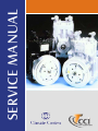
service manual
n All cast iron wear surfaces (including permanent
cast iron cylinder liners, cast iron piston rings, cast
iron crankshaft and cast iron shaft seal plate).
n High load ball bearings (no needle bearings or
sleeve bushings are utilized).
n High strength aluminum alloy pistons and
connecting rods permanently secured by steel
wrist and dowel pins.
n Swedish steel reed valve assemblies, highly
finished for maximum performance as well as
maximized orifice porting to reduce the effects of
liquid slugging.
n Value added features like a generously lubricated shaft seal area, high quality steel head
gaskets and the widest selection of compressor
service valves available.
n Large oil sump produces a unique splash
lubrication system that allows the compressor to be
self-lubricating regardless of the amount of oil
mixed with refrigerant.
08/98 SUPERSEDES FORMS: 180.72-NM • 180.72-NM2 • 180.72-RP • YA77-401
Table of Contents
Compressor Specifications................................................................................................................... 2
Heavy Duty and Standard Models ............................................................................................... 2
Super-Compact ("Mini") Models ................................................................................................... 3
Compressor Identification..................................................................................................................... 4
Features ............................................................................................................................................... 5
Installation ............................................................................................................................................ 6
Inspection ............................................................................................................................................. 7
Oil Charge .................................................................................................................................... 7
Oil Type ........................................................................................................................................ 7
Leak Check Equipment ................................................................................................................ 8
Evacuation, Leak Testing, Adjustment ......................................................................................... 8
Rotation-Speed ............................................................................................................................ 8
Service ................................................................................................................................................. 9
Clutch Servicing ........................................................................................................................... 9
Shaft Seal Servicing ................................................................................................................... 10
Head and Valve Plate Servicing ................................................................................................. 12
Baseplate Servicing ................................................................................................................... 13
Gasket Treatment ...................................................................................................................... 14
Notes on Noise Complaints ........................................................................................................ 14
Torque Sequence and Specifications ................................................................................................ 15
Trouble Shooting ................................................................................................................................ 16
Retro-Fix II Retrofit Procedure ........................................................................................................... 17
Shaft Identification Detail ................................................................................................................... 17
Compressor Service Valves and Fittings ........................................................................................... 18
Service Parts ...................................................................................................................................... 20
1
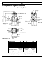
Compressor Specifications
Heavy Duty Models
DIMENSIONS: IN. (mm)
SPECIFICATIONS
No. Cylinders
Bore, in. (mm)
Stroke, in. (mm)
Disp., cu. in./rev. (cc/rev)
R.P.M. - Max.
Refrigerant
Initial Oil Charge, fl. oz. (ml)*
Weight, lbs. (kg)
Lubrication
206
209
210
2
2
2
1.875 (47.63)
1.875 (47.63)
1.875 (47.63)
1.105 (28.07)
1.573 (39.95)
1.866 (47.40)
6.10 (100)
8.69 (142)
10.3 (169)
6000
6000
6000
R-12, 22, 502, 134a R-12, 22, 502, 134a R-12, 22, 502, 134a
& new blends
& new blends
& new blends
14 (413)
14 (413)
14 (413)
14.6 (6.6)
14.6 (6.6)
14.6 (6.6)
Splash and Positive Pressure and Oil Return Through Suction Side
*R-12 Heavy Duty models contain 12 fl. oz. (355 ml).*R-134a Heavy Duty models contain
14 fl. oz. (413 ml). Some OEM specifications are as high as 17 fl. oz. (503 ml).
2
Compressor Specifications
Super-Compact ("Mini") Models
DIMENSIONS: IN. (mm)
SPECIFICATIONS
No. Cylinders
Bore, in. (mm)
Stroke, in. (mm)
Disp., cu. in./rev. (cc/rev)
R.P.M. - Max.
Refrigerant
Initial Oil Charge, fl. oz. (ml)*
Weight, lbs. (kg)
Lubrication
NOTE: Super-Compact models are designed to have
the fittings on the top or from the rear (low profile).
SC 206
SC 209
2
2
1.875 (47.63)
1.875 (47.63)
1.105 (28.07)
1.573 (39.95)
6.10 (100)
8.69 (142)
6000
6000
R-12, 22, 502, 134a
R-12, 22, 502, 134a
& new blends
& new blends
12 (355)
12 (355)
13.0 (5.9)
13.3 (6.0)
Splash and Positive Pressure and Oil Return Through Suction Side
*Some OEM specifications are as high as 15 fl. oz. (444 ml).
3
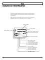
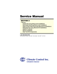
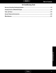
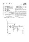
Compressor Identification
The metal nameplate located at the top front of the compressor serves as a
means of identification. The location permits viewing the nameplate with the
clutch installed.
Data inscribed on the nameplate includes the serial number, combination
model/part number, date of manufacture, and type of refrigerant.
SERIAL NUMBER
PART NUMBER
O
MODEL NUMBER
N . A 01234567
PT.
ER 210L - 00000
MONTH OF MANUFACTURE
YEAR OF MANUFACTURE
00-00
Climate Control Inc.
REFRIGERANT 134a
TYPE OF REFRIGERANT
R = RIGHT HAND SUCTION
L = LEFT HAND SUCTION
10 = 10 CUBIC INCH DISPLACEMENT
09 = 9 CUBIC INCH DISPLACEMENT
06 = 6 CUBIC INCH DISPLACEMENT
2 = TWO CYLINDERS
R = ROTALOCK CYLINDER HEAD
T = TUBE 'O' CYLINDER HEAD
F = FLANGE CYLINDER HEAD
E = EQUIPMENT (HEAVY DUTY MODEL)
SC = SUB-COMPACT (MINI)
4
Features
TRUE UNIVERSAL MOUNT — Can be installed and
operated in any position from horizontal left to horizontal
right as received. No field adjustments are necessary.
If the compressor is mounted horizontally, the suction
side should be on top.
• Crankcase — Light weight die cast noncorrosive
aluminum.
UNIVERSAL ROTATION — Compressor rotation can be
clockwise or counter-clockwise. No field adjustments are
necessary.
• Head — Die cast aluminum.
LUBRICATION SYSTEM — A splash lubrication system
provides more than adequate lubrication to the front and
rear crankshaft bearings, connecting rods and cylinder
walls. Positive pressure differential between the crankcase and the suction intake is utilized to provide lubrication to the front shaft seal.
• Piston — Die cast aluminum fitted with cast iron
piston rings for optimum wear.
TWO OIL PLUGS — One on each side of the crankcase,
permits easy checking of crankcase oil level regardless
of mounting position.
• Crankshaft — Cast ductile iron. Large connecting rod
and main bearing areas.
EXTERNAL CLUTCH MOUNT — Four bosses on the
seal end of the crankcase provide accommodation for
mounting the clutch. Simplifies field replacement of
compressor shaft seals.
SERVICEABILITY — All components readily accessible
and removable with standard tools.
• Cylinder Liners — Cast iron, permanently cast into
crankcase body. Precision honed finish.
• Base — Die cast aluminum.
• Connecting Rods — Die cast aluminum, heavy cross
section, super-finished surfaces, assembly doweled
for positive alignment.
• Bearings — High load capacity ball type bearings for
longer life at heavy loads and high speed.
• Valves — Swedish steel suction and discharge
valves mounted on ground valve plate.
• Shaft Seal — Carbon face seal specially designed for
high speed operation.
• Gaskets — Neoprene composite fiber gaskets used
to seal base plate and valve plate. Rubber coated
metal gaskets used to seal cylinder head.
5
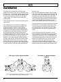
Installation
The compressor mounting bracket must be rigidly
secured to the vehicle engine. It is recommended to use
at least six 3/8" - 16 UNC bolts of proper length to secure
the compressor to the mounting brackets. Mounting with
the side mounting holes is preferred over the bottom
mounting holes. Lock washers must be used with all
mounting bolts.
Refer to pages 2 and 3 for compressor dimensions and
physical data.
Very important factors in compressor installation are
correct pulley alignment and proper belt tension. The
compressor flywheel, or clutch, must be in perfect
alignment with the drive pulley on the engine and any
auxiliary idler or belt adjustment pulley arrangements. It
is important to be sure that the shaft key is in place on
the shaft and the flywheel bolt is drawn tight, when
installing a flywheel or clutch. The pulley alignment may
be checked by holding a 1/2" dia. (12-13 mm) rod - 2 to 3
feet (0.6 to 0.9 m) long - firmly in the V groove of the
flywheel or clutch making sure the rod falls squarely in
the driver pulley grooves. A further check may be made
by seeing that the belt, as it goes from pulley to pulley,
comes off the pulley grooves perfectly straight and that
there are no side-way bends in the belt, as it approaches
or leaves the pulleys. Only high quality reinforced belts
180 degree, left to right orientation
NOTE: CCI recommends that when positioning compressor at full
90° horizontal, suction side should be on "top".
6
should be used.
The belt tension adjustment should be made so the belt
is taut, but not too taut to create excessive bearing loads.
Due to the pulsating load created by the compressor, the
belt tension must be greater than for a normal steady
load. Belt tension can be accurately determined with the
use of a belt tension gauge which gives a direct reading
of belt load as determined by the deflection. A belt
tension of 100-120 lbs. (45-54 kg) is considered normal.
After approximately 30 minutes of operation time, the belt
should stretch to a normal operation point and a further
check for proper tension should be made. Good alignment and belt tension are important to insure long belt
life, quiet operation, and to maintain top system performance.
The discharge and suction line connections must be
made to the proper compressor service valves or fittings.
The word DISCH. on the cylinder head designates the
discharge service valve port. The word SUCTION on the
cylinder head designates the suction service valve port.
Because the compressor will move, or float, with the
engine upon acceleration, rigid connections to the
compressor should be avoided, and suitable flexible
refrigerant lines, which will permit compressor movement
without causing excessive tubing strain, should be used.
Clockwise or counterclockwise
rotation
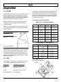
Inspection
OIL CHARGE
If the quantity of oil is unknown, the compressor oil level
must be checked at the time of installation and again
after the system has been fully charged with refrigerant
and the system has been operated and balanced out to
the desired compartment interior temperature.
The Table below shows the crankcase oil charge in fluid
ounces (and ml) at various dip stick measurements for
both horizontal and vertical mounts. The oil charge after
the system is stabilized should be maintained with 6 fluid
ounces (177 ml) minimum and 8 to 12 fluid ounces (237
to 355 ml) for best results.
OIL CHARGE vs. DIP STICK DEPTH
Make the initial oil level check after the compressor is
mounted on the mounting bracket and before initial
refrigerant charge.
HEAVY DUTY & STANDARD MODELS
Horizontal
Mount
Vertical
Mount
*45°
Mount
Remove one oil fill plug with its “O” ring, either plug on a
vertical mount installation, the upper plug on horizontal
mount installations.
6 fl. oz.
(177 ml)
13/16"
(21 mm)
7/8"
(22 mm)
1 5/8"
(41 mm)
8 fl. oz.
(237 ml)
1"
(25 mm)
1"
(25 mm)
1 13/16"
(46 mm )
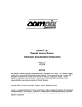
LEFT HAND MOUNTING:
CHECK OIL WHEN NON ROK SHAFT
KEY IS DOWN.
10 fl. oz.
(296 ml)
1-3/16"
(30 mm)
1-1/8"
(29 mm)
2"
(51 mm)
12 fl. oz.
(355 ml)
1-5/8"
(41 mm)
1-7/16"
(37 mm)
2 1/4"
(57 mm)
14 fl. oz.
(414 ml)
1-13/16"
(46 mm)
1-11/16"
(43 mm)
2 7/16"
(62 mm)
16 fl. oz.
(473 ml)
1-15/16"
(49 mm)
1-7/8"`
(48 mm)
2 5/8"
(67 mm)
RIGHT HAND MOUNTING:
CHECK OIL WHEN NON ROK SHAFT
KEY IS UP.
SUPER COMPACT ("MINI") MODELS
Horizontal Mount
Vertical Mount
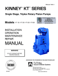
FIG. 1-OIL DIP STICK
6 fl. oz.
(177 ml)
3/4"
(19 mm)
1"
(25 mm)
The oil dip stick, Fig. 1, can be made locally (or purchased, page 15) and is suitable for use on all compressors in any mounting position. If made locally, it can be
formed from 1/8" dia. X 8-5/16" (3 mm dia x 210 mm)
long stock, preferably non ferrous material which is not
subject to corrosion. Notched ends are helpful in visibly
detecting the oil depths.
8 fl. oz.
(237 ml)
1"
(25 mm)
1-1/4"
(32 mm)
10 fl. oz.
(296 ml)
1-3/16"
(30 mm)
1-1/2"
(38 mm)
12 fl. oz.
(355 ml)
1-7/16"
(37 mm)
1-13/16"
(46 mm)
14 fl. oz.
(414 ml)
1-3/4"
(44 mm)
2-1/16"
(52 mm)
OIL TYPE
*OIL LEVEL AT 45°
When adding or changing oil, use only proper oil. Keep
the oil storage container tightly capped at all times.
Refrigerant
R-12, R-22
R-502
Acceptable Lubricants
Mineral Oil, Zerol 150,
Zerice S-68, P.O.E.
R-134a
Polyol Ester (P.O.E.) P.A.G.
Other Refrigerants
Consult Factory
}
Measurement up dip stick
7
The compressor oil level should never be permitted to go
below the minimum oil level of 6 fluid ounces (177 ml). If
oil must be added, the oil should be added until the level
is 12 fluid ounces (355 ml). An excessive amount of oil is
detrimental to the proper functioning of the entire system.
If a compressor replacement is made on a system which
has been in operation, the oil charge of the new compressor should not exceed 12 fluid ounces (355 ml),
unless specified by the OEM manufacturer.
When inserting the oil fill plug, the sealing “O” ring is
slipped over the oil fill plug threads in such a manner that
the “O” ring is not twisted. Insert the oil plug in the oil fill
opening and tighten the plug snug. If the plug leaks, do
not attempt to stop the leak by over tightening the oil
check plug. A leak may be caused by dirt under the “O”
ring or on the seat, a fractured “O” ring, or a damaged
seat on the oil fill plug or oil fill opening. To stop leaks at
the oil fill plug, correct the mechanical damages and
insert a new “O” ring.
It must be remembered that the 206, 209 and 210
models are high speed compressors and satisfactory
operation depends on proper lubrication.
LEAK CHECK EQUIPMENT
Most of the electronic leak checkers now on the market
are capable of locating very small refrigerant leaks. Since
open type bolted and flanged compressors have a
permissible leak rate of one ounce per year, it then
becomes quite important that the leak check equipment
used be calibrated to pick up only those leaks which are
in excess of the permissible one ounce per year limit.
Since shaft seals depend upon oil for lubrication and
sealing, it is quite natural to find oil in the shaft cavity.
This oil is heavily laden with refrigerant and electronic
equipment would pick up this refrigerant and indicate it
as a leak. When checking the shaft seal for leakage, the
refrigerant-laden oil must first be flushed from the seal
cavity with a solvent which does not affect the operation
of the electronic leak equipment. Caution: some of the
more common solvents contain chemical compositions
which affect the operation of the leak detector equipment.
The major point to consider in any electronic type leak
detection equipment is to be able to positively calibrate
the equipment to the permissible leak rate and then to
use the equipment as explained by its manufacturer. The
speed at which the probe is moved is very important in
locating the larger than permissible leaks.
8
EVACUATION, LEAK TESTING,
ADJUSTMENT
The instructions contained in the installation and service
manual of the air conditioning system manufacturer
should be followed in evacuating and charging the
system and for adjustment of all controls.
After charging, the entire system should be checked for
leaks with a leak detector.
ROTATION-SPEED
The compressor may be operated in either a clockwise
or counter-clockwise direction of rotation. No field
adjustments are necessary. The compressor is designed
for operation between 500 and 6,000 rpm maximum.
(4000 rpm continuous rating).
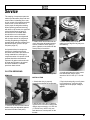
Service
The majority of compressor parts are
made up of aluminum alloys and care
must be taken in handling not to mar,
nick or scratch. All machined surfaces
must be free of nicks and burrs to
insure proper fit and gasket seating.
When replacing parts and securing
with bolts or cap screws, the specified
torque requirements on page 15
should never be exceeded. Bolts
should all be run in until the bolt
heads make contact, then tightened
with a torque wrench in a sequence
resulting in tightening of diagonally
opposite bolts until all are drawn up to
specified torques. (Refer to torque
sequence page 15.)
An important factor in compressor
servicing is cleanliness and care
should be exercised to prevent dirt or
foreign material from entering the
compressor when it is opened. All old
gaskets should be removed and
replaced. All gasket surfaces should
be clean and all parts to be reused
should be washed in a suitable
petroleum base solvent.
2. Install clutch removal bolt into the
clutch. Using the adjustable spanner
wrench to hold the clutch pulley in
place, tighten the clutch bolt until the
clutch pulley is forced free.
CLUTCH SERVICING
REMOVAL
3. Remove the clutch mounting bolts.
INSTALLATION
1. Check that a key is properly
inserted in the shaft of the compressor.
1. Remove the clutch center bolt and
washer using the adjustable spanner
wrench to hold the clutch pulley.
3. Place clutch pulley over shaft
making sure to align the key way over
the shaft key.
4. Install and tighten the clutch center
bolt and washer using a torque
wrench to 20-25 ft. lbs. (27.1-33.9 Nm).
5. Spin the clutch pulley to verify there
is no interference. Verify the clutch
engages when the proper voltage is
applied.
2. Mount and center the coil bracket.
Tighten the four clutch mounting bolts
using a torque wrench to 13-19 ft. lbs.
(17.6-25.8 N-m). NOTE: Only use
bolts that have a loctite patch on the
threads.
9
NOTE:Theshaf
tseali
nt
hi
sdesi
gni
sacar
bonf
acesealwhi
chi
sdesi
gnedt
ot
r
apoi
lbet
weent
he
st
at
i
onar
ymet
alpl
at
eandt
her
ot
at
i
ngcar
bonr
i
ng.T
omai
nt
ai
nt
hei
nt
egr
i
t
yoft
heshaf
tseali
ti
s
r
ecommendedt
or
ot
at
et
heshaf
tever
yt
hr
eet
osi
xmont
hs.
2. Apply clean refrigerant oil to the
seal plate “O” ring and place the ring
into the seal plate “O” ring groove.
Invert the plate and observe that the
“O” ring remains in place.
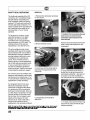
8. With the tool used to remove the
seal retainer assembly, carefully pry
up and remove the friction ring (boot).
Again, use care not to scratch or mar
the crankshaft or machined face of
the compressor.
INSTALLATION
1. Use a clean, lint free shop cloth to
wipe the crankshaft clean. Note: At
this time the front main bearing is
exposed, therefore care must be
taken to prevent dirt or any type of
contamination from falling into it.
5. Prior to installation, check the seal
assembly to make sure that the
carbon seal ring is right side up
(narrow polished band up), and
confirm that the carbon rings notches
are aligned with the drive tabs in the
metal seal retainer. Lightly place the
seal assembly (carbon ring side up)
onto the oiled crankshaft.
3. Place a few drops of clean refrigerant oil on the face of the seal plate
between the "O" ring and the inside
diameter and with a clean finger
spread the oil into a thin film. It is
important that the surface not be over
oiled and that there is no oil between
the "O" ring groove and the outside
diameter of the seal plate.
4. Apply clean refrigerant oil around
the entire exposed end of the crankshaft. With a clean finger, uniformly
spread the oil completely over the
surface. Again, take care that no dirt
or contamination falls onto he main
bearing.
6. Insert the alignment tool into the seal
plate and lightly place the plate’s
polished face into contact with the seal
assembly. With a uniform downward
motion, use the alignment tool to push
the seal plate into contact with
11
REMOVAL
the crankcase face. Continue to hold
pressure between the seal plate and
the crankcase face while aligning and
installing the six (6) hold down
screws. Use a nut driver or similar
tool for initial tightening. Failure to
hold the seal plate against the
crankcase face until all screws are
firm against the seal plate may
result in a chipped or broken
carbon ring. Remove the centering
tool and use a star pattern sequence
to tighten the six (6) screws to a finish
torque of 5-8 ft. lb.
(7-11 N-m).
7. Install the metal dust cover, tapping
it firmly into place.
8. Install felt ring dust shield, placing it
around the seal plate and tight against
the compressor housing.
9. Reinstall the clutch, using the four
new screws supplied with the seal kit
to attach the field coil assembly,
tighten these screws to 13-19 ft.lb.
(18-26 N-m). Install the clutch armature/pulley assembly and tighten the
center bolt to 20-25 ft.lb. (27-34 N-m)
Insure that the pulley spins freely.
Remove the caps from the suction
and discharge ports, and using the
tool that tightened the center bolt,
rotate the compressor six (6) to ten
(10) revolutions to seat the carbon
ring uniformly against the seal plate.
Replace the suction and discharge
port caps.
HEAD AND VALVE PLATE
SERVICING
Prior to servicing the head and valve
plate, both service valves should be
opened to free any gas pressure
which may be in the compressor. The
cylinder head is made of aluminum
and care should be taken when
removing it not to damage the sealing
surfaces.
12
1. Remove the screws from flanged
type service valves. Note that these
four screws are longer than the
remaining head screws. If the valves
are of the Rotalock type or Tube 'O'
type, remove by loosening the hex
nuts which are a part of the valve
assembly.
2. Remove the remaining screws in
the head and remove the valve plate
and head from the cylinder by prying
or tapping under the ears which
extend from the valve plate. If the
head and valve plate adhere, hold the
head and tap the valve plate ears
away from the head with a soft
hammer. Do not hit or tap the head to
separate the head and valve plate
because damage to the head may
result.
3. All gasket material adhering to the
head, valve plate, or crankcase;
should be carefully removed in such a
manner that the machined sealing
surfaces are not scratched or nicked.
BASEPLATE SERVICING
REMOVAL
INSTALLATION
Valves and valve plates are furnished
only as a complete assembly.
1. Apply a thin film of clean refrigeration oil on the area of the crankcase
to be covered by the crankcase
gasket. Place the cylinder gasket in
position on the cylinder so the dowel
pins in the crankcase go through the
dowel pin holes in the cylinder gasket.
2. Apply a thin film of clean refrigeration
oil to the top and bottom valve plate
areas to be covered by gaskets. Place
the valve plate in position on the
cylinder gasket so the discharge valve
assemblies (i.e. the smaller diameter
assemblies with the restrainer over the
valve reed) are facing up and the
locating dowel pins go through the
dowel pin holes in the valve plate.
5. For a flange head, apply a thin film
of clean refrigeration oil to the service
valve flanges. Place an oiled service
valve O-ring or gasket in position on
the cylinder head service valve
flanges. Place the service valves in
position on the proper service valve
ports (suction or discharge) and insert
the four longer screws through the
service valve mounting pads, the
head, the valve plate, and into the
crankcase. For a Tube 'O' or Rotalock
head, insert the longer torx screws on
the inside of the service valve ports
and the shorter torx screws on the
outside. Insert the remaining head
screws and run in all the screws until
the heads make contact. Tighten the
head and service valve screws (using
a torque wrench) to 17-25 ft. lbs.
(23.0-33.9 N-m) in sequence as
shown on torque sequence chart,
page 15.
1. Remove the baseplate bolts.
2. Remove baseplate and gasket. If
the baseplate is stuck, lightly tap the
edges of the baseplate with a soft
hammer.
3. Remove any gasket material
adhering to the baseplate or crankcase. This should be done in a
manner such that the sealing surfaces are not scratched or nicked.
INSTALLATION
1. Apply a thin film of refrigeration oil
to a new gasket and the sealing
surface of the crankcase and baseplate.
3. Place the head gasket, with the bead
facing up, in position on the valve plate
so the dowel pins go through the dowel
pin holes in the gasket.
4. Apply a light film of clean refrigeration oil on the machined surface of the
cylinder head which matches the head
gasket. Place the head on the cylinder
head gasket so the dowel pins go into
the dowel pin holes in the head.
2. Properly align the gasket on the
crankcase.
13
NOTES ON NOISE COMPLAINTS
Many of the noise complaints can be traced to mount and drive and other related
component problems. Normally if the unit is noisy at one speed and this noise
clears up at another, it is not usually due to the compressor. Each vehicle has its
critical frequencies where all vibrations get into the correct harmony to generate
sound or noise. The speed at which these critical points are found will vary with
each vehicle and each mount and drive arrangement. By changing the mount
and drive components the noise level may be reduced.
Many times the noise generated can be eliminated or greatly reduced by changing the belt adjustment to a different tension. A tension of 100 -120 lbs. (45-54
kg) is considered normal.
3. Install the baseplate and bolts.
Tighten baseplate bolts to 10-16 ft.
lbs. (13.6-21.7 N-m) in sequence
given on page 15 using a torque
wrench.
GASKET TREATMENT
Before assembly to the compressor,
all gaskets should be dipped in clean
refrigeration oil of the type used in the
crankcase.
Noises emanating from the clutch are difficult to recognize because of the close
connecting feature with the compressor. A loose bolt holding the clutch to the
shaft will result in extremely noisy operation. Extreme care must be exercised
to prevent the removal of the wrong component.
Since a compressor has many moving parts, it is normal for it to generate some
noise just as a motor generates some noise as it is operated. The refrigerant
gases, as they are moved by the compressor pistons, also produce noises and
vibrations as a normal situation.
Gaskets are made of a neoprene
composition fiber and wicking action
will result as oil follows the fiber. Do
not mistake this wicking action for
leaking. Wicking is a normal condition
and is to be expected.
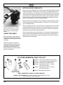
CLASSIC # 22-1272
CCI (YORK) ESSENTIAL SEAL TOOL KIT
1
2
3
4
5
6
99-431 99-474 99-499 99-440 -
CCI and Tecumseh Oil Level Checker
Seal Installer and Plate Alignment Tool
Universal Clutch Holder Wrench
Clutch Remover 5/8 x 11 Thread
(CCI and Tecumseh)
99-441 - Clutch Remover 5/8 x 18 Thread
(CCI and Tecumseh)
99-473 - Universal Seal Remover
BASIC COMPRESSOR TOOLS AVAILABLE THROUGH:
CLASSIC TOOL DESIGN, INC. 31 WALNUT STREET • NEW WINDSOR, NY 12553
PH. 914-562-8700 • FAX 914-562-8596
14
Torque Sequence and Specifications
Heavy Duty and Standard Models
Super Compact ("Mini") Models
LOCATION
Baseplate
Rear Bearing Cover Plate
Cylinder Head
Seal Plate
Oil Fill Plug
Clutch Mounting Screw
Clutch Center Bolt
Rotalock Valve
Tube 'O' Valve
Flange Valve
Pressure Relief Valve
THREAD
1/4" - 20 UNC
1/4" - 20 UNC
5/16" - 18 UNC
10-24 UNC
3/8" - 24 UNF
1/4" - 20 UNC
5/16" - 24 UNF
1" - 14 UNS
1" 14 UNS
5/16" - 18 UNC
3/8" - 24 UNF
HEAD
Hex
Flat
Hex
Hex
Hex
Hex
Hex
Hex
Hex
Torx
Hex
FIELD TORQUE SPECS
10-16 ft.-lb. (13.6-21.7 N-m)
10-16 ft.-lb. (13.6-21.7 N-m)
17-25 ft.-lb. (23.0-33.9 N-m)
5-8 ft.-lb. (6.8-10.8 N-m)
5-10 ft.-lb. (6.8-13.6 N-m)
13-19 ft. lb. (17.6-25.8 N-m)
20-25 ft. lb. (27.1-33.9 N-m)
35-40 ft. lb. (47.5-54.2 N-m)
35-40 ft.-lb. (47.5-54.2 N-m)
17-25 ft.-lb. (23.0-33.9 N-m)
5-10 ft.-lb. (6.8-13.6 N-m)
15
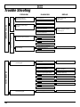
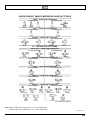
Trouble Shooting
No unusual compressor noise
High Suction Pressure
Low Discharge Pressure
DIAGNOSIS
1. Inspect Valve Plate Reed
& Gasket Areas
REPAIR
Replace Valve Plate
and Gaskets
2. Consult System Manual
Low Suction and Discharge
Pressures
1. Check for Low Refrigerant Charge
2. Leak Check Compressor
Replace Shaftseal, Gaskets,
Oil Fill Plug, etc.
3. Consult System Manual
Internally noisy compressor
IMPROPER COOLING
PROBLEM
1. Check Belt Tension
Intermittent or Non-Functioning
2. Check Clutch Volts & Amps
3. Consult System Manual
Rough Running
1. Check Compressor Temperature,
Component Parts Run-out
Change out Compressor
2. Consult System Manual
Clutch Engaged
1. Check Compressor Mounting
Components
Torque to Specs
EXCESSIVE NOISE
2. Check for Other Engine Noise
3. Check for Clutch Slippage
Replace if Needed
4. Check for Proper Refrigerant Charge
Charge as Necessary
5. Check Clutch Components Clearing, etc.
Replace if Needed
6. Check Compressor Oil Level
Fill to Recommended Level
7. Check Valve Plate
Replace if Needed
8. Consult System Manual
1. Check for Slippage
Clutch Not Engaged
16
Replace if Needed
RETRO-FIX II Retrofit Procedure
This P.O.E. (Ester) lubricant is approved for use in R-134a Climate Control 2-cylinder compressor (York) systems. It may
not be suitable in other compressors. Use for oil additions in R-134a systems or for retrofitting of R-12 systems. RETROFIT PER VEHICLE MANUFACTURER RECOMMENDATIONS and in accordance with SAE J1661, J1660, J1639, J1629,
J2197 and J1989. Barrier hoses are required for R-134a systems. Heavy-duty vehicles equipped with these hoses can
normally be retrofit by following these guidelines:
1.
2.
3.
4.
5.
6.
7.
8.
9.
10.
11.
Diagnose and repair all A/C system malfunctions, (Flush system only if contamination exists).
Recover the R-12 refrigerant.
Remove compressor and drain oil from sump.
Replace receiver/dryer with one containing XH-7 or XH-9 desiccant.
Change high and low side service ports to R-134a type by using adapters, new service valves, etc., per SAE J1660.
Add 14 fl. ounces of RETRO-FIX II P.O.E. (Ester) oil to compressor and install on vehicle.
Evacuate system (45 minutes, minimum).
Charge system with R-134a. (Usually 15-20% less R-134a by weight will fully charge an R-12 system.)
Leak test system.
Run system to confirm normal operation.
Install label to identify that the system has been retrofit per SAE J1660.
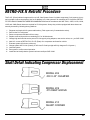
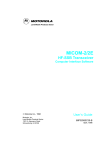
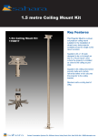
Shaft Detail Indicating Compressor Displacement
MODEL 206
.030 X 45° CHAMFER
MODEL 209
.015 DEEP GROVE
MODEL 210
SHARP CORNER
17
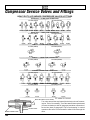
Compressor Service Valves and Fittings
HEAVY DUTY & STANDARD COMPRESSOR VALVES & FITTINGS
ROTOLOCK — FLARE HOSE CONNECTION
1/2 FLARE (SIZE #8)
5/8 FLARE (SIZE #10)
ROTOLOCK — O RING HOSE CONNECTION
1/2 O RING (SIZE #8)
5/8 O RING (SIZE #10)
TUBE 'O' — FLARE HOSE CONNECTION
1/2 O RING (SIZE #8)
5/8 O RING (SIZE #10)
TUBE 'O' — O RING HOSE CONNECTION
1/2 O RING (SIZE #8)
5/8 O RING (SIZE #10)
FLANGE — FLARE HOSE CONNECTION
1/2 FLARE (SIZE #8)
5/8 FLARE (SIZE #10)
FLANGE — O RING HOSE CONNECTION
1/2 O RING (SIZE #8)
5/8 O RING (SIZE #10)
BACK SEATING VALVE STEM
GAUGE PORT
HOSE CONNECTION
18
Turn valve stem all the way forward (clockwise) to shut off connecting line. This is "front seating". Turn valve stem all the way backward
(counter-clockwise) to shut off gauge port and allow connection of
service line (hose) to gauge port. This is "back seating". In normal
operation valve stem is "back seated" to allow full flow through the
valve.
SUPER-COMPACT (MINI) COMPRESSOR VALVES & FITTINGS
YOKE — FLARE HOSE CONNECTION
1/2 FLARE (SIZE #8)
5/8 FLARE (SIZE #10)
TE
OLE
OBS
YOKE — O RING HOSE CONNECTION
1/2 O RING (SIZE #8)
5/8 O RING (SIZE #10)
FLANGE — FLARE HOSE CONNECTION
1/2 FLARE (SIZE #8)
5/8 FLARE (SIZE #10)
R - 134a VALVES & FITTINGS
ROTOLOCK — O RING HOSE CONNECTION
1/2 O RING (SIZE #8)
5/8 O RING (SIZE #10)
FLANGE — O RING HOSE CONNECTION
1/2 O RING (SIZE #8)
5/8 O RING (SIZE #10)
YOKE — O RING HOSE CONNECTION
1/2 O RING (SIZE #8)
5/8 O RING (SIZE #10)
TUBE 'O' — FLARE HOSE CONNECTION
1/2 FLARE (SIZE #8)
5/8 FLARE (SIZE #10)
TUBE 'O' — O RING HOSE CONNECTION
1/2 O RING (SIZE #8)
5/8 O RING (SIZE #10)
NOTE: SIZE #8 O RING HOSE CONNECTION = 3/4" - 16 UNC THREAD SIZE
SIZE #10 O RING HOSE CONNECTION = 7/8" - 14 UNC THREAD SIZE
S88-21923 REV K
19
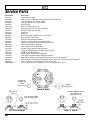
Service Parts
Part Number
021-12373
022-25020
022-25103
022-25104
026-19841
028-21549
028-07146
028-25131
029-25173
029-09888
088-21831
388-20905
488-16314
488-16316
488-16319
488-16346
488-16999
488-20322
488-20610
488-20797
488-20798
488-20799
488-21802
488-25274
488-25080
ESTER-25065
Description
Oil Fill Plug (all models)
Plastic Cap For Rotalock and Tube 'O' Heads (includes rubber seal)
16mm High Side R-12 to R-134a adapter
13mm Low Side R-12 to R-134a adapter
Suction Screen
O-Ring For Oil Plug and P.R.V.
Teflon Ring (white) 3/4" For Rotolock Heads
Felt Ring (oil wick and dust seal)
Oil Dip Stick
Shaft Key
Oil Wick Assembly (standard & heavy duty models)
Pressure Relief Valve (P.R.V.)
Rotolock Head Assembly W/Gaskets
Gasket Kit - All Standard and Heavy Duty Models
Valve Plate and Reed Assembly W/Gaskets (standard)
Flange Head Assembly W/Gaskets
Tube 'O' Head Assembly W/Gaskets
SC (Mini) Flange Head Assembly W/Gaskets
Valve Plate and Reed Assembly W/Gaskets (heavy duty)
Gasket Kit - SC (Mini) Models
SC (Mini) Blank Head Assembly W/Gaskets
Valve Plate and Reed Assembly W/Gaskets (SC Mini)
Shaft Seal Kit (Neoprene) All Refrigerants Including R-12, R-134a and Blends
Deluxe Neoprene All Refrigerants Seal Kit W/Felt Ring, Centering Tool, Special Clutch Coil Screws
Classic "Tool" Kit (Compressor Repair and Clutch Removal)
P.O.E. (ESTER) Oil 14 Ounce Bottles (12 to a Case) "RETRO-FIX II" Brand
ROUND OR
SQUARE CUT
O-RING
(NEW STYLE)
GASKET
(OLD STYLE)
FLANGE HEAD
R CAST IN
ROUND RUBBER O-RING
INCLUDED WITH
FITTING OR VALVE
HEAD
FLAT TEFLON O-RING
INSTALLED IN HEAD
ROTOLOCK HEAD
20
TUBE 'O' HEAD
United States
Office
European Marketing/
Engineering Office
2120 N. 22nd Street
Decatur, Illinois 62526
217-422-0055 phone
217-422-4323 fax
BWD Automotive GMBH
Regerstrasse 4
D-22761 Hamburg
Germany
49/40-89 05 92 0 phone
49/40-89 05 92 33 fax