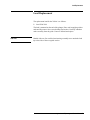
1
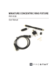
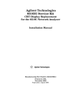
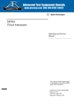
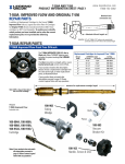
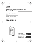
Agilent Technologies 914A and
914B Moving Loads
Operating and Service
Manual
Agilent Part Number: 00914-90017
Printed in USA
Print Date: October 2000
Supersedes: October 1980
Notice
The information contained in this document is subject to change without
notice.
Agilent Technologies makes no warranty of any kind with regard to this
material, including, but not limited to, the implied warranties of
merchantability and fitness for a particular purpose. Agilent Technologies
shall not be liable for errors contained herein or for incidental or
consequential damages in connection with the furnishing, performance, or
use of this material.
Agilent Technologies assumes no responsibility for the use or reliability of
its software on equipment that is not furnished by Agilent Technologies.
This document contains proprietary information which is protected by
copyright. All rights are reserved. No part of this document may be
photocopied, reproduced, or translated to another language without prior
written consent of Agilent Technologies.
RESTRICTED RIGHTS LEGEND
Use, duplication, or disclosure by the U.S. Government is subject to
restrictions as set forth in subparagraph (c)(1)(ii) of the Rights in Technical
Data and Computer Software clause at DFARS 252.227-7013 for DOD
agencies, and subparagraphs (c)(1) and (c)(2) of the Commercial Computer
Software Restricted Rights clause at FAR 52.227-19 for other agencies.
Agilent Technologies, Inc.
1400 Fountaingrove Parkway
Santa Rosa, CA 95403-1799, U.S.A.
© Copyright Agilent Technologies, Inc. 2000
ii Agilent 914A/B Operating and Service Manual
What You’ll Find in this Manual…
•
•
•
•
Overview, page 1
Specifications, page 2
Load Replacement, page 3
Performance Test, page 4
Agilent 914A/B Operating and Service Manual iii
Warranty
Custom systems are warranted by contractual agreement between Agilent
Technologies and the customer.
Certification
Agilent Technologies, Inc., certifies that this product met its published
specifications at the time of shipment from the factory. Agilent Technologies
further certifies that its calibration measurements are traceable to the
United States National Institute of Standards and Technology (NIST,
formerly NBS), to the extent allowed by the Institute’s calibration facility,
and to the calibration facilities of other International Standards
Organization members.
Warranty
This Agilent Technologies system product is warranted against defects in
materials and workmanship for a period corresponding to the individual
warranty periods of its component products. Instruments are warranted for a
period of one year. During the warranty period, Agilent Technologies will, at
its option, either repair or replace products that prove to be defective.
Warranty service for products installed by Agilent Technologies and certain
other products designated by Agilent Technologies will be performed at
Buyer’s facility at no charge within Agilent Technologies service travel
areas. Outside Agilent Technologies service travel areas, warranty service
will be performed at Buyer’s facility only upon Agilent Technologies’ prior
agreement and Buyer shall pay Agilent Technologies’ round trip travel
expenses. In all other areas, products must be returned to a service facility
designated by Agilent Technologies.
For products returned to Agilent Technologies for warranty service, Buyer
shall prepay shipping charges to Agilent Technologies and Agilent
Technologies shall pay shipping charges to return the product to Buyer.
However, Buyer shall pay all shipping charges, duties, and taxes for products
returned to Agilent Technologies from another country.
Agilent Technologies warrants that its software and firmware designated by
Agilent Technologies for use with an instrument will execute its
programming instructions when properly installed on that instrument.
Agilent Technologies does not warrant that the operation of the instrument,
or software, or firmware will be uninterrupted or error free.
LIMITATION OF WARRANTY. The foregoing warranty shall not apply
to defects resulting from improper or inadequate maintenance by Buyer,
Buyer-supplied software or interfacing, unauthorized modification or
misuse, operation outside of the environmental specifications for the
product, or improper site preparation or maintenance.
iv Agilent 914A/B Operating and Service Manual
NO OTHER WARRANTY IS EXPRESSED OR IMPLIED. AGILENT
TECHNOLOGIES SPECIFICALLY DISCLAIMS THE IMPLIED
WARRANTIES OR MERCHANTABILITY AND FITNESS FOR A
PARTICULAR PURPOSE.
EXCLUSIVE REMEDIES. THE REMEDIES PROVIDED HEREIN ARE
BUYER’S SOLE AND EXCLUSIVE REMEDIES. AGILENT
TECHNOLOGIES SHALL NOT BE LIABLE FOR ANY DIRECT,
INDIRECT, SPECIAL, INCIDENTAL, OR CONSEQUENTIAL
DAMAGES, WHETHER BASED ON CONTRACT, TORT, OR ANY
OTHER LEGAL THEORY.
YEAR 2000. Agilent Technologies warrants that each Agilent Technologies
hardware, software, and firmware product on Agilent Technologies’
Corporate Price List (dated July 1, 1998 or later) delivered under the
product’s contract of sale will be able to accurately process date data
(including, but not limited to, calculating, comparing, and sequencing) from,
into, and between the twentieth and twenty-first centuries, and the years
1999 and 2000, including leap year calculations, when used in accordance
with the product documentation provided that all other products (that is,
hardware, software, firmware) used in combination with such Agilent
Technologies product(s) properly exchange date data with it. If the
agreement requires that specific Agilent Technologies products must
perform as a system in accordance with the foregoing warranty, then that
warranty will apply to those Agilent Technologies products as a system, and
Customer retains sole responsibility to ensure the year 2000 readiness of its
information technology and business environment. The duration of this
warranty extends through January 31, 2001.
The remedies available under this warranty will be defined in, and subject to,
the terms and limitations of the warranties contained in the contract of sale.
To the extent permitted by local law, this warranty applies only to branded
Agilent Technologies products and not to products manufacture by others
that may be sold or distributed by Agilent Technologies. Nothing in this
warranty will be construed to limit any rights or remedies provided
elsewhere in the contract of sale with respect to matters other than year 2000
compliance.
Assistance
Product maintenance agreements and other customer assistance agreements
are available for Agilent Technologies products.
For assistance, call your local Agilent Technologies Sales and Service Office
(refer to “Service and Support” on page vi).
Agilent 914A/B Operating and Service Manual v
Service and Support
Any adjustment, maintenance, or repair of this product must be performed
by qualified personnel. Contact your customer engineer through your local
Agilent Technologies Service Center. You can find a list of local service
representatives on the Web at:
http://www.agilent.com/find/assist
Click on “Contact Us” and select your country.
If you do not have access to the Internet, one of these centers can direct you
to your nearest representative:
United States:
(800) 403-0801
Canada:
(877) 429-9969
Europe:
(41 22) 780.6111 (Switzerland)
(33 1) 69 82 66 66 (France)
(49 7031) 464-6222 (Germany)
(44 188) 9696622 (Great Britain)
Japan:
0120-32-0119
Latin America:
(11) 7297-3700 (Brazil)
Australia/New Zealand:
1-800-802-540 (Australia)
0800-738-378 (New Zealand)
Asia-Pacific:
080-047-669
vi Agilent 914A/B Operating and Service Manual
Safety and Regulatory Information
Review this product and related documentation to familiarize yourself with
safety markings and instructions before you operate the instrument. This
product has been designed and tested in accordance with international
standards.
WARNING
The WARNING notice denotes a hazard. It calls attention to a procedure,
practice, or the like, that, if not correctly performed or adhered to, could result
in personal injury. Do not proceed beyond a WARNING notice until the
indicated conditions are fully understood and met.
CAUTION
The CAUTION notice denotes a hazard. It calls attention to an operating
procedure, practice, or the like, which, if not correctly performed or adhered
to, could result in damage to the product or loss of important data. Do not
proceed beyond a CAUTION notice until the indicated conditions are fully
understood and met.
Instrument Markings
!
When you see this symbol on your instrument, you should refer to the instrument’s
instruction manual for important information.
This symbol indicates hazardous voltages.
The laser radiation symbol is marked on products that have a laser output.
This symbol indicates that the instrument requires alternating current (ac) input.
The CE mark is a registered trademark of the European Community. If it is
accompanied by a year, it indicates the year the design was proven.
The CSA mark is a registered trademark of the Canadian Standards Association.
1SM1-A
This text indicates that the instrument is an Industrial Scientific and Medical Group 1
Class A product (CISPER 11, Clause 4).
This symbol indicates that the power line switch is ON.
This symbol indicates that the power line switch is OFF or in STANDBY position.
Agilent 914A/B Operating and Service Manual vii
Safety Earth
Ground
This is a Safety Class I product (provided with a protective earthing
terminal). An uninterruptible safety earth ground must be provided from the
main power source to the product input wiring terminals, power cord, or
supplied power cord set. Whenever it is likely that the protection has been
impaired, the product must be made inoperative and secured against any
unintended operation.
Before Applying Power
Verify that the product is configured to match the available main power
source as described in the input power configuration instructions in this
manual. If this product is to be powered by autotransformer, make sure the
common terminal is connected to the neutral (grounded) side of the ac power
supply.
viii Agilent 914A/B Operating and Service Manual
Overview
Description
The Agilent 914A and 914B moving load consists of a section of waveguide
which is mounted in a tapered, low-reflection load. By means of a plunger,
the load may be moved longitudinally in the waveguide at least 1/2
wavelength at the lowest waveguide frequency. Since reflections from the
load can occur in any phase by moving the load, at a single frequency the
reflection from the load can be separated from those caused by a
discontinuity in the transmission system.
The difference between the 914A and 914B is the waveguide section. The
914A section is standard waveguide stock. The waveguide section of the
914B is a precision machined waveguide section which is held at very close
tolerance.
Uses
For single and swept-frequency transmission and reflection measurements a
moving load is a convenient means of determining how much of a SWR is
due to the termination. Use of the 914 for swept-frequency attenuation,
impedance and directivity measurements is described in Agilent Application
Note 183, High Frequency Swept Techniques. Copies of this Note are
available from the Agilent Technologies Sales and Service Offices.
CAUTION
Use the knob on the shaft to move the load forward and backward only. Do
not rotate this knob, as this will loosen the load and damage your 914A/B.
The thumbscrew should be rotated to lock the load in place, or to unlock it
prior to moving the load.
Preventive
Maintenance
Protect the face of the coupling flange from damage. Any scoring or burring
of the mating surfaces causes discontinuity; the resulting increase in SWR
degrades performance. The protective cap part number is 5040-0354.
Agilent 914A/B Operating and Service Manual 1
Specifications
Specifications
Table 1
Agilent X914A/B Specifications
Characteristic
Value
Frequency Range
8.20 to 12.4 (GHz)
Waveguide ID (in)
0.900x0.400 in
±0.001
Tolerance
Waveguide Size (EIA)
WR90
Equivalent Flange
UG135/U
SWR Load (max.)
1.01
SWR Waveguide (max.)
1.005
Power Rating
1W
Dimensions (Length)1
10.125 in (257 mm)
Weight
.875 lbs (0.4 kg)
1. Nominal length with shaft fully extended.
2 Agilent 914A/B Operating and Service Manual
Load Replacement
Load Replacement
The replacement load for the X914A is as follows:
•
Load 5020-3206
The load is mounted on the end of the plunger. Place unit in upright position
and carefully remove four screws holding load section. Carefully withdraw
entire assembly from the guide. Unscrew old load and replace.
CAUTION
Handle with care. Be careful when inserting assembly not to touch the load
tip to the sides of the waveguide section.
Agilent 914A/B Operating and Service Manual 3
Performance Test
Performance Test
Do the following performance tests for incoming inspection, after repair, or
any other time the performance of the load is suspect. The SWR is measured
by measuring the reflection coefficient, The SWR is related t o the reflection
coefficient (ρ) by the expression:
SWR = 1 + [ρ] / 1 - [ρ]
Fixed Frequency
Reflection Coefficients
Figure 1
Table 2
Calibration
Connect the equipment as shown in Figure 1. External ALC operation is not
essential. The 20 dB coupler and detector #1 may be eliminated without
degrading results. Refer also to Table 2.
Reflection Coefficient Setup
Equipment Required for Reflection Coefficient Measurement
Measurement Frequencies
(GHz)
Sweep OSC
Low Pass Filter
Isolator
8.20 and 12.4 GHz
8690B-8694B
X362A
I-155L
Set the sweep oscillator for CW output at lowest frequency.
Internal-squarewave modulate the output at 1000 Hz. Connect adjustable
short to standard section. Tune slide-screw tuner #1 so SWR meter reading is
less than 1.02 SWR as adjustable short is moved.
4 Agilent 914A/B Operating and Service Manual
Performance Test
Remove adjustable short and insert moving load (with defective load) into
standard section. Phase load for maximum reading on SWR meter. Tune
slide-screw tuner #2 for a minimum reading on SWR meter(-60 dB
RANGE). Phase (move) the load for a maximum reading on the SWR meter
and adjust the gain for a reading of 0 dB on the SWR meter scale. Tune
slide-screw tuner #2 spindle only for a reading of a loss of 6 dB. Phase load
and readjust slide-screw tuner #2, if necessary, to obtain a maximum meter
excursion of 0.2 dB as load is phased. Directivity signal is now below –79
dB.
Set calibrating attenuator to 40.0 dB and remove moving load from standard
section. Reconnect adjustable short and set SWR meter RANGE and GAIN
to a convenient meter reference. Move calibration attenuator from 35 to 50
dB and check the SWR meter response. Remove adjustable short and set
calibrating attenuator to 0 dB.
NOTE
If necessary, insert an appropriate microwave amplifier between sweep
oscillator output and low-pass filter for better resolution. If an amplifier is
inserted, be sure to repeat the above calibration.
Return Loss
Measurement
Connect 914A/B to be tested to standard section. Phase the load and measure
the difference in dB between the minimum and maximum SWR, meter
readings. Get corrections from Signal Separation Chart (Figure 2) and add
them to the smallest dB reading. One of these figures is the body reflection
and the other the load reflection. If it is necessary to identify these
reflections, as when one figure meets specifications but the other does not,
refer to the next paragraph.
Maximum Body Reflection
–53.0 dB
Maximum Load Reflection
–46.7 dB
The small error caused by the imperfectly-tuned-outdirectivity of the reverse
coupler is allowed for in these test limits.
If it necessary to identify the reflections, temporarily increase the body
reflection by placing a fibre washer or a small piece of wire into the 914
waveguide near the flange end. Repeat the measurements and use Figure 2 to
separate the two signals.
CAUTION
Be sure to remove this added material when the test is completed.
Agilent 914A/B Operating and Service Manual 5
Performance Test
Figure 2
Signal Separation Chart
6 Agilent 914A/B Operating and Service Manual