1
®
E stablished 1981
Advanced Test Equipment Rentals
www.atecorp.com 800-404-ATEC (2832)
911D/E Sliding Load
Operating and Service
Manual
Manual Part Number: 00911-90019
Printed in USA
July 2001
Supersedes: June 2000
Notice
The information contained in this document is subject to change without
notice.
Agilent Technologies makes no warranty of any kind with regard to this
material, including, but not limited to, the implied warranties of
merchantability and fitness for a particular purpose. Agilent Technologies
shall not be liable for errors contained herein or for incidental or
consequential damages in connection with the furnishing, performance, or
use of this material.
Agilent Technologies assumes no responsibility for the use or reliability of
its software on equipment that is not furnished by Agilent Technologies.
This document contains proprietary information which is protected by
copyright. All rights are reserved. No part of this document may be
photocopied, reproduced, or translated to another language without prior
written consent of Agilent Technologies.
RESTRICTED RIGHTS LEGEND
Use, duplication, or disclosure by the U.S. Government is subject to
restrictions as set forth in subparagraph (c)(1)(ii) of the Rights in Technical
Data and Computer Software clause at DFARS 252.227-7013 for DOD
agencies, and subparagraphs (c)(1) and (c)(2) of the Commercial Computer
Software Restricted Rights clause at FAR 52.227-19 for other agencies.
Agilent Technologies, Inc.
1400 Fountaingrove Parkway
Santa Rosa, CA 95403-1799, U.S.A.
© Copyright Agilent Technologies, Inc. 2000
ii Agilent 911D/E Operating And Service Manual
In This Manual…
•
•
•
•
•
•
•
•
Overview, page 1
Specifications, page 2
Handling Precautions and Inspection, page 3
Principles of Operation, page 4
Performance Tests, page 7
Adjustments, page 8
Replacing the Load Element, page 9
Replaceable Parts, page 11
Agilent 911D/E Operating And Service Manual iii
Warranty
Custom systems are warranted by contractual agreement between Agilent
Technologies and the customer.
Certification
Agilent Technologies, Inc., certifies that this product met its published
specifications at the time of shipment from the factory. Agilent Technologies
further certifies that its calibration measurements are traceable to the
United States National Institute of Standards and Technology (NIST,
formerly NBS), to the extent allowed by the Institute’s calibration facility,
and to the calibration facilities of other International Standards
Organization members.
Warranty
This Agilent Technologies system product is warranted against defects in
materials and workmanship for a period corresponding to the individual
warranty periods of its component products. Instruments are warranted for a
period of one year. During the warranty period, Agilent Technologies will, at
its option, either repair or replace products that prove to be defective.
Warranty service for products installed by Agilent Technologies and certain
other products designated by Agilent Technologies will be performed at
Buyer’s facility at no charge within Agilent Technologies service travel
areas. Outside Agilent Technologies service travel areas, warranty service
will be performed at Buyer’s facility only upon Agilent Technologies’ prior
agreement and Buyer shall pay Agilent Technologies’ round trip travel
expenses. In all other areas, products must be returned to a service facility
designated by Agilent Technologies.
For products returned to Agilent Technologies for warranty service, Buyer
shall prepay shipping charges to Agilent Technologies and Agilent
Technologies shall pay shipping charges to return the product to Buyer.
However, Buyer shall pay all shipping charges, duties, and taxes for products
returned to Agilent Technologies from another country.
Agilent Technologies warrants that its software and firmware designated by
Agilent Technologies for use with an instrument will execute its
programming instructions when properly installed on that instrument.
Agilent Technologies does not warrant that the operation of the instrument,
or software, or firmware will be uninterrupted or error free.
LIMITATION OF WARRANTY. The foregoing warranty shall not apply
to defects resulting from improper or inadequate maintenance by Buyer,
Buyer-supplied software or interfacing, unauthorized modification or
misuse, operation outside of the environmental specifications for the
product, or improper site preparation or maintenance.
iv Agilent 911D/E Operating And Service Manual
NO OTHER WARRANTY IS EXPRESSED OR IMPLIED. AGILENT
TECHNOLOGIES SPECIFICALLY DISCLAIMS THE IMPLIED
WARRANTIES OR MERCHANTABILITY AND FITNESS FOR A
PARTICULAR PURPOSE.
EXCLUSIVE REMEDIES. THE REMEDIES PROVIDED HEREIN ARE
BUYER’S SOLE AND EXCLUSIVE REMEDIES. AGILENT
TECHNOLOGIES SHALL NOT BE LIABLE FOR ANY DIRECT,
INDIRECT, SPECIAL, INCIDENTAL, OR CONSEQUENTIAL
DAMAGES, WHETHER BASED ON CONTRACT, TORT, OR ANY
OTHER LEGAL THEORY.
YEAR 2000. Agilent Technologies warrants that each Agilent Technologies
hardware, software, and firmware product on Agilent Technologies’
Corporate Price List (dated July 1, 1998 or later) delivered under the
product’s contract of sale will be able to accurately process date data
(including, but not limited to, calculating, comparing, and sequencing) from,
into, and between the twentieth and twenty-first centuries, and the years
1999 and 2000, including leap year calculations, when used in accordance
with the product documentation provided that all other products (that is,
hardware, software, firmware) used in combination with such Agilent
Technologies product(s) properly exchange date data with it. If the
agreement requires that specific Agilent Technologies products must
perform as a system in accordance with the foregoing warranty, then that
warranty will apply to those Agilent Technologies products as a system, and
Customer retains sole responsibility to ensure the year 2000 readiness of its
information technology and business environment. The duration of this
warranty extends through January 31, 2001.
The remedies available under this warranty will be defined in, and subject to,
the terms and limitations of the warranties contained in the contract of sale.
To the extent permitted by local law, this warranty applies only to branded
Agilent Technologies products and not to products manufacture by others
that may be sold or distributed by Agilent Technologies. Nothing in this
warranty will be construed to limit any rights or remedies provided
elsewhere in the contract of sale with respect to matters other than year 2000
compliance.
Assistance
Product maintenance agreements and other customer assistance agreements
are available for Agilent Technologies products.
For assistance, call your local Agilent Technologies Sales and Service Office
(refer to “Service and Support” on page vi).
Agilent 911D/E Operating And Service Manual v
Service and Support
Any adjustment, maintenance, or repair of this product must be performed
by qualified personnel. Contact your customer engineer through your local
Agilent Technologies Service Center. You can find a list of local service
representatives on the Web at: http://www.agilent.com/find/assist
If you do not have access to the Internet, one of these centers can direct you
to your nearest representative:
United States
(tel) 1 800 452 4844
Latin America
(tel) (305) 269 7500
(fax) (305) 269 7599
Canada
(tel) 1 877 894 4414
(fax) (905) 282-6495
New Zealand
(tel) 0 800 738 378
(fax) (+64) 4 495 8950
Japan
(tel) (+81) 426 56 7832
(fax) (+81) 426 56 7840
Australia
(tel) 1 800 629 485
(fax) (+61) 3 9210 5947
Europe
(tel) (+31) 20 547 2323
(fax) (+31) 20 547 2390
Asia Call Center Numbers
Country
Phone Number
Fax Number
Singapore
1-800-375-8100
(65) 836-0252
Malaysia
1-800-828-848
1-800-801664
Philippines
(632) 8426802
1-800-16510170 (PLDT Subscriber Only)
(632) 8426809
1-800-16510288 (PLDT
Subscriber Only)
Thailand
(088) 226-008 (outside Bangkok)
(662) 661-3999 (within Bangkok)
(66) 1-661-3714
Hong Kong
800-930-871
(852) 2506 9233
Taiwan
0800-047-866
(886) 2 25456723
People’s Republic of
China
800-810-0189 (preferred)
10800-650-0021
10800-650-0121
India
1-600-11-2929
000-800-650-1101
vi Agilent 911D/E Operating And Service Manual
Safety and Regulatory Information
Review this product and related documentation to familiarize yourself with
safety markings and instructions before you operate the instrument. This
product has been designed and tested in accordance with international
standards.
WARNING
The WARNING notice denotes a hazard. It calls attention to a procedure,
practice, or the like, that, if not correctly performed or adhered to, could result
in personal injury. Do not proceed beyond a WARNING notice until the
indicated conditions are fully understood and met.
CAUTION
The CAUTION notice denotes a hazard. It calls attention to an operating
procedure, practice, or the like, which, if not correctly performed or adhered
to, could result in damage to the product or loss of important data. Do not
proceed beyond a CAUTION notice until the indicated conditions are fully
understood and met.
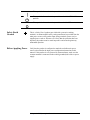
Instrument Markings
When you see this symbol on your instrument, you should refer to the
instruments instruction manual for important information.
This symbol indicates hazardous voltages.
This symbol indicates that the instrument requires alternating current
(ac) input.
The CE mark is a registered trademark of the European Community. If
it is accompanied by a year, it indicates the year the design was proven.
The C-Tick mark is a registered trademark of the Australian Spectrum
Management Community.
The CSA mark is a registered trademark of the Canadian Standards
Association.
1SM1-A
This text indicates that the instrument is an Industrial Scientific and
Medical Group 1 Class A product (CISPER 11, Clause 4).
Agilent 911D/E Operating And Service Manual vii
This symbol indicates that the power line switch is ON.
This symbol indicates that the power line switch is in STANDBY
position.
This symbol indicates that the power line switch is OFF
Safety Earth
Ground
This is a Safety Class I product (provided with a protective earthing
terminal). An uninterruptible safety earth ground must be provided from the
main power source to the product input wiring terminals, power cord, or
supplied power cord set. Whenever it is likely that the protection has been
impaired, the product must be made inoperative and secured against any
unintended operation.
Before Applying Power
Verify that the product is configured to match the available main power
source as described in the input power configuration instructions in this
manual. If this product is to be powered by autotransformer, make sure the
common terminal is connected to the neutral (grounded) side of the ac power
supply.
viii Agilent 911D/E Operating And Service Manual
Typeface Conventions
•
Used to emphasize important information:
Use this software only with the Agilent 8494A/B, 8495A/B,
8496A/B.
•
Used for the title of a publication:
Refer to the Agilent 911D/E Operating And Service Manual.
•
Used to indicate a variable:
Type LOAD BIN filename.
Instrument Display
•
Used to show on-screen prompts and messages that you will see on the
display of an instrument:
The Agilent 8494A/B, 8495A/B, 8496A/B will display the message
CAL1 SAVED.
[Keycap]
•
Used for labeled keys on the front panel of an instrument or on a
computer keyboard:
Press [Return].
{Softkey}
•
Used for simulated keys that appear on an instrument display:
Press {Prior Menu}.
User Entry
•
Used to indicate text that you will enter using the computer keyboard;
text shown in this typeface must be typed exactly as printed:
Type LOAD PARMFILE
•
Used for examples of programming code:
Italics
#endif // ifndef NO_CLASS
Path Name
•
Used for a subdirectory name or file path:
Edit the file usr/local/bin/sample.txt
Computer Display
•
Used to show messages, prompts, and window labels that appear on a
computer monitor:
The Edit Parameters window will appear on the screen.
•
Used for menus, lists, dialog boxes, and button boxes on a computer
monitor from which you make selections using the mouse or keyboard:
Double-click EXIT to quit the program.
Agilent 911D/E Operating And Service Manual ix
Overview
This operating and service manual provides information for the Agilent
911D/E sliding loads. The Agilent 911D/E each have a single APC-3.5 male
connector.
Description
The coaxial sliding load and mismatch are movable, low reflection loads
used to make precision microwave measurements. By moving the load, its
reflection can be separated from the other reflections in the system. This
technique allows you to measure the directivity of coaxial directional
couplers and the residual standing wave ratio (SWR) of coaxial slotted lines.
The sliding mismatch is mechanically similar to the sliding load except that
its reflection is somewhat higher so that a known mismatch can be
introduced into a system for calibration. The reflection is between 23 dB and
28 dB over the frequency range from 3 to 26.5 GHz.
The sliding load contains a hollow cylindrical iron-bearing plastic load
element that surrounds the center conductor. The gradual tapering of the load
element enables it to absorb the applied RF energy.
The load element can be moved within the instrument body at least one-half
of a wavelength at the lowest rated frequency (3 GHz). Some applications
may require that the load element be moved in precise steps. There are 6
marks scribed along the body of the load. Use these marks for optimum
calibration of the vector network analyzer.
Agilent 911D/E Operator Manual 1
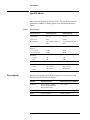
Specifications
Specifications
Instrument specifications are listed in Table 1. The specifications are the
performance standards, or limits, against which the instrument may be
tested.
Table 1
Specifications
Specified Information
Agilent 911D Load
Agilent 911E Load
Connector type
APC 3.5
APC 3.5
Connector sex
Male
Female
Frequency range
3 to 26.5 GHz (usable to 33
GHz)
3 to 26.5 GHz (usable to 33
GHz)
<0.004
<0.004
<0.004
<0.004
1W
I kW
1W
1 kW
Load stability (plus connector
and air line)
3 to 20 GHz
20 to 26.5 GHz
Power rating
Average
Peak
Load element travel
Half of a wavelength at 3.0 GHz (5 cm minimum)
Dimensions
Length
Weight
Environment
25.6 cm (10.1 in)
120 g (4.25 oz)
25.6 cm (10.1 in)
120 g (4.25 oz)
Keep the environments where the instrument is to be used or stored and
shipped within the following conditions.
Parameter
Equipment Operation
Equipment Storage and Shipping
Temperature
+15 °C to +35 °C (or network
analyzer operating temperature
range, whichever is less)
-40 °C to +70 °C
Relative Humidity
<80% relative humidity at 40 °C
<90% relative humidity at 40 °C
Altitude
<4,570 m (15,000 ft)
<15,300 m (50,000 ft)
2 Agilent 911D/E Operator Manual
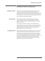
Handling Precautions and Inspection
Handling Precautions and Inspection
Handling Precautions
Initial Inspection
Do not drop or otherwise mechanically damage the instrument. Do not
remove the center conductor unnecessarily since bowing the center
conductor causes the SWR to change. The instrument should be kept in its
original carrying case when it is not being used. The case helps prevent dust
from forming on the center conductor. Dust can become abrasive and can
interfere with the load performance capability.
Check the shipping container and cushioning materials for damage.
Carefully examine the contents for possible damage incurred during
shipment. Check the contents received with the packing list to verify the
shipment is complete.
If the contents are incomplete or damaged, or the instrument fails its
electrical performance test (use the procedures in your network analyzer’s
operating and service manual), notify an Agilent Technologies Sales and
Service Office engineer. In addition, notify the carrier and retain the
shipping materials for the carrier’s inspection.
Packaging Materials
Original shipping containers should be retained in the event the instrument
needs to be returned to the factory. Materials identical to those used are
available for purchase through an Agilent Technologies Sales and Service
Office. When returning instruments to the factory, include a completed
service tag. The tag should state the type of service needed, your address, the
instrument model number and its serial number. Mark the container
FRAGILE to assure careful handling. Refer to the instrument by model
number and serial number in any correspondence.
Agilent 911D/E Operator Manual 3
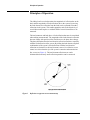
Principles of Operation
Principles of Operation
The sliding load is used to determine the magnitude of reflection due to the
load, and the magnitude of fixed reflections due to the system. By moving
the load element, the reflection from the load can be separated from other
reflections in the system. This enables quantities such as the directivity of
coaxial directional couplers or residual SWR of coaxial slotted lines to be
measured.
The load connector and body have a fixed reflection that must be considered
when making measurements. The magnitude of the load element’s reflection
does not change with position of the load, however, the phase does change.
The phase determines how the load element’s reflection combines vectorially
with the fixed reflection of the system. By sliding the load element, all phase
combinations of the system’s fixed reflections with the load element’s
reflection are obtained. As the load element is moved, its reflection vector
rotates in a circle about the tip of the system’s connector and transmission
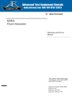
line vector (see Figure 1). The load element reflection error can be
eliminated and extremely small reflection quantities can be measured.
Figure 1
Reflection Coefficient Vector Relationship
4 Agilent 911D/E Operator Manual
Principles of Operation
Connecting the Load
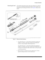
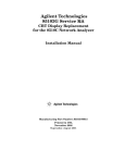
Figure 2
Check that the mating-plane surfaces and center conductors are clean and
free of grit. To connect the load and ensure that the center conductor and
conductor body are making good contact, refer to Figure 2 and proceed as
follows.
Illustrated Parts Breakdown
1. For Agilent 911E use a 3.5 mm female pin-depth gage (Agilent part
number 11752-60021), and a torque wrench set to 8 inch-pounds
(0.9N-m). Set the pin depth to 0.000 inch protrusion.
For Agilent 911D use a 3.5 mm male pin depth-gage (Agilent part
number 11752-60020), and a torque wrench set to 8 inch-pounds. Use a
centering bead (Agilent part number 85052-20057) to set the pin-depth
to 0.000 inch protrusion.
2. Release the lock (1) and mate the center conductor pin (17) firmly
against the mating connector’s center-conductor pin.
Agilent 911D/E Operator Manual 5
Principles of Operation
CAUTION
Keep the center conductors of the two connectors aligned. Misalignment
causes damage to the female center conductor pin.
3. Thread on the coupling nut. Use a torque wrench set to 8 inch-pounds
(0.9 N-m) and torque the connector bodies.
4. After ensuring the center conductor pins are correctly mated, latch the
lock (1).
Periodically inspect and clean the load’s center and outer conductor
surfaces at the reference plane for wear and debris.
Disconnecting the Load
CAUTION
Avoid damaging the center conductor. Keep the center conductor in locked
position while you disconnect the load.
Avoid damage to the swivel assembly. To lock the center conductor while the
load is disconnected, you must first make sure to pull the handle back
completely, before setting the handle down into the locked position.
6 Agilent 911D/E Operator Manual
Performance Tests
Performance Tests
Verification of instrument performance over its specifications is achieved by
measuring the network analyzer’s system directivity. Refer to the operating
manual of the network analyzer under calibration for the directivity
performance test.
Agilent 911D/E Operator Manual 7
Adjustments
Adjustments
The center conductor in the instrument may be adjusted for connector pin
depth. Use a pin-depth gage as specified in “Connecting the Load” on
page -5. Once the pin-depth is set, lock the center conductor and adjust the
set screw beneath the lock handle. Use a torque wrench set to 8 inch-pounds
(0.9 N-m).
8 Agilent 911D/E Operator Manual
Replacing the Load Element
Replacing the Load Element
To replace the iron-bearing plastic load element, use Figure 2 for reference
as you follow the procedure below:
Dissemble the Load
1. Spread the tabs on the handle (1) to free it from the spiral pin (3).
2. Pull the handle away from the swivel assembly (4), being careful not to
lose the spring (2) from the internal hole in the handle.
3. Squeeze the tabs of the swivel assembly together to free them from the
two holes in the end of the handle.
4. Use a small, flat-bladed screwdriver to remove the tuning element (5)
from the end of the load element (18). If needed, use a heat-gun to soften
the glue securing the tuning element so that it can be removed.
5. Carefully remove the spiral pin (3) from the load body (9).
6. Carefully remove the center conductor (17). Be very careful not to bend
and damage the center conductor.
7. Move the sliding load handle (8) toward the handle end of the load
assembly.
a. Use a small posi-drive screwdriver to remove the load screw (7).
b. Very carefully and gently remove the load element (18) from the
body.
c. Slide the load handle off the end of the body.
d. If necessary, remove to replace the 0-ring.
8. Clean a dirty load, internally, using a small diameter rod (about 0.035 to
0.040 inches diameter).
NOTE
Hold the load near the collar as you clean it. Do not hold it near the end that
has the diagonal cut.
a. Use compressed air to blow out any dirt inside the load. Be careful
not to damage the diagonal cut at the end of the load.
b. Wrap a bit of cotton around the end of the rod.
c. Swab the inside of the load with back and forth motions, finally
pushing the swab out the end with the aluminum collar.
Agilent 911D/E Operator Manual 9
Replacing the Load Element
d. Carefully inspect, and then clean the center conductor with a cotton
swab. Be careful not to bend the center conductor.
e. Replace a damaged or worn center conductor.
9. Remove the coupling nut (14) from the 911D.
a. Remove the retaining ring (12).
b. Slide the coupling nut back to allow the ball bearings (13) to drop
out through the hole in the nut.
c. After removing all 12 ball bearings, slide the coupling nut off the
end of the load body.
Reassemble the Load
1. Insert the load into the handle-end of the body, diagonal cut end first.
a. Align the hole in the aluminum collar with the long slot in the body.
b. Move the sliding load handle so that the hole in the handle aligns
with the hole in the aluminum collar.
c. Drop the load screw (7) into the hole in the handle.
d. Carefully, thread then tighten the screw into the collar. If the screw
does not thread into the load collar, damage can result.
2. Move the sliding load handle toward the rear of the load body.
a. Insert the center conductor (17) into the body and align the hole in
the center conductor with the long and short slots in the body.
b. Insert the spiral pin (3) through the slots and the hole in the end of
the center conductor.
3. To complete the reassembly, follow the steps in the disassembly
procedure in reverse order.
10 Agilent 911D/E Operator Manual
Replaceable Parts
Replaceable Parts
Table 2 lists the replaceable parts for the load. To order a replaceable part,
address your order or inquiry to one of the Agilent Technologies Sales and
Service Offices listed at the end of this document.
In your correspondence to the office, include the instrument’s model number,
the part number needed, and a brief description of the part.
NOTE
In addition you may order the Sliding Load Handle Replacement Kit,
Agilent part number 85052-60047.
Table 2
Load Assembly Replaceable Parts
Item Number
Part Number
Description
1
00911-20055
Handle
2
1460-0212
Compression spring
3
1480-0722
Spiral Pin
4
00915-40008
Swivel assembly
4
5021-9682
Plunger-slider load (p/o swivel assembly)
(911E)
5
9135-0344
Tuning element
6
0905-1138
O-Ring (0.375 in x 0.500 in)
7
00915-20006
Load screw
8
00911-20055
Sliding-load body
9
00911-20061
Male body (911D)
9
00911-20062
Female body (911E)
10
00911-40005
Extrusions
11
Not Assigned
12
1250-2078
Retaining ring (911D)
13
1410-0059
Ball BPG Type (911D)
14
5021-7070
Coupling nut (911D)
15
00911-20059
Support plug
16
00911-20063
Center conductor carriage
17
00911-20047
Male center conductor (911D)
17
00911-20049
Female center conductor (911E)
Agilent 911D/E Operator Manual 11
Replaceable Parts
Item Number
Part Number
Description
18
00911-20064
Load element (911D/E)
18
00911-20065
Blunt load element (911E)
19
00911-80009
ID label (911D)
19
00911-80010
ID label (911E)
20
5021-6558
Slotless contact (911E)
21
1401-0200
Protective cover (911D)
21
1401-0202
Protective cover (911E)
22
85052-20057
Centering bead (911E)
12 Agilent 911D/E Operator Manual