1
A90-0130
Modular Multi System
Service Manual
Air Conditioner – Multi Split Type System
HFC R407C
Contents
Introduction . . . . . . . . . . . . . . . . . . . . . . . . . . . . . . . . . . . . . . . . . . . . 4
1
Summary . . . . . . . . . . . . . . . . . . . . . . . . . . . . . . . . . . . . . . . . . . . . . . 6
2
Outline of MMS (Modular Multi System) . . . . . . . . . . . . . . . . . . . 8
3
Parts Specifications . . . . . . . . . . . . . . . . . . . . . . . . . . . . . . . . . . . . 10
4
Construction Views – Outdoor Units . . . . . . . . . . . . . . . . . . . . . . 14
5
Construction Views – Indoor Units . . . . . . . . . . . . . . . . . . . . . . . . 15
6
Wiring Diagrams . . . . . . . . . . . . . . . . . . . . . . . . . . . . . . . . . . . . . . 19
7
Refrigerant Piping Systematic Drawings . . . . . . . . . . . . . . . . . . 25
8
Combined Refrigerant Piping Systematic Drawings . . . . . . . . 28
9
Refrigerant Cycle Schematic . . . . . . . . . . . . . . . . . . . . . . . . . . . . . 32
10
Outline of Control . . . . . . . . . . . . . . . . . . . . . . . . . . . . . . . . . . . . . . 33
11
Self Diagnostic Display Information . . . . . . . . . . . . . . . . . . . . . . 46
12
Control Circuit Configuration . . . . . . . . . . . . . . . . . . . . . . . . . . . . 50
13
Troubleshooting . . . . . . . . . . . . . . . . . . . . . . . . . . . . . . . . . . . . . . . 55
14
Backup Operation . . . . . . . . . . . . . . . . . . . . . . . . . . . . . . . . . . . . 101
15
Forced Function of Oil Level Detection . . . . . . . . . . . . . . . . . . . 105
16
Refrigerant Pipe Installation . . . . . . . . . . . . . . . . . . . . . . . . . . . 106
17
Trial Operation . . . . . . . . . . . . . . . . . . . . . . . . . . . . . . . . . . . . . . . 111
18
Exploded Views and Service Parts. . . . . . . . . . . . . . . . . . . . . . . 124
19
Additional Literature and Contacts . . . . . . . . . . . . . . . . . . . . . . 134
20
3
Introduction
Precautions
1
Read these Safety Notes carefully before installing this unit.
These Safety Notes contain very important safety information. Always be sure to observe these
cautions.
After installation is complete, trial the operation of the unit to make sure that it is operating
normally. Instruct the customer about how to operate the unit, and about necessary
maintenance.
The dealer or a special contractor must install this unit.
Attempts to install this unit by a customer could result in leaks, electric shock, or fire.
Improper installation could result in leaks, electric shock, or fire.
If this unit is installed in a small room, measures must be taken to ensure that, even
in the event of a refrigerant leak, the maximum safe limit for refrigerant
concentration levels in the air is not exceeded.
Consult the dealer for details on what measures can be taken to keep from exceeding the
maximum safe limit. If a refrigerant leak does cause refrigerant concentration levels in the air
to exceed the maximum safe limit, asphyxiation could result.
Select a location for installation that will be able to safely bear the weight of the unit.
If the installation location is not strong enough to support the unit and the unit falls, injury
could result.
Install the unit in the prescribed manner to withstand strong (hurricane-level) winds
and earthquakes.
Insufficiently secure installation could allow the unit to tip over, fall, or otherwise cause an
accident.
Ventilate the area if any refrigerant leaks during installation.
If the refrigerant comes into contact with an open flame, it will produce a toxic gas.
After completing installation, make sure that no refrigerant is leaking.
If the refrigerant leaks indoors and comes into contact with an open flame in a water heater,
stove, oven, or other such appliance, it will produce a toxic gas.
Electrical work must be performed by a qualified electrician as described in the
Installation Manual.
The unit must be connected to its own independent circuit. Inadequate circuit capacity or
improper installation could result in electric shock or fire.
Wiring must be performed securely, using the prescribed cables.
The cables must be secured in a manner that prevents any force that pulls on the cables from
being relayed to the terminal connectors. If the cables are not connected or secured properly,
fire or other accidents could result.
The unit must be grounded.
Do not connect the ground wire to a gas pipe, water pipe, lightning rod, or telephone
ground wire. When wiring the system to the main power source, follow the standards
established by the local power company. Inadequate grounding can result in electric shock.
Do not install the unit in a location where combustible gases could conceivably leak.
Leaking gases that accumulate in the vicinity of the unit could be ignited by the unit.
4
Introduction
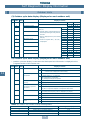
Components
1. Outdoor Unit
1
Inverter unit
Fixed-speed unit
Appearance
Corresponding HP
8HP
Model name
10HP
6HP
8HP
10HP
MM-A0224HT MM-A0280HT MM-A0160HX MM-A0224HX MM-A0280HX
Cooling capacity (kW)
22.4
28.0
16.0
22.4
28.0
Heating capacity (kW)
25.0
31.5
18.0
25.0
31.5
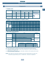
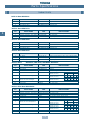
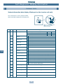
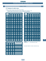
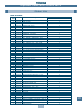
2. Outdoor Units (Combination of Outdoor Units)
16HP 18HP 20HP 22HP 24HP 26HP 28HP 30HP 32HP 34HP 36HP
38HP 40HP 42HP 44HP 46HP
Combined Model MM-A~HT 0224 0280 0384
Corresponding HP
8HP
10HP 14HP
0440 0504 0560 0608 0672
0728 0784 0840
0896 0952 1008
1064 1120 1176
Cooling capacity (kW)
44.8
67.2
72.8
89.6
95.2 100.8 106.4 112.0 117.6 123.2 128.8
28.0
8HP
10HP
8HP
8HP 10HP 10HP
8HP
8HP
10HP 10HP 10HP
8HP
10HP 10HP
10HP 10HP 10HP 10HP 10HP
—
—
6HP
8HP
8HP
10HP
8HP
8HP
8HP
10HP 10HP
8HP
8HP
10HP
10HP 10HP
8HP
10HP 10HP
—
—
—
—
—
—
6HP
8HP
8HP
8HP
10HP
8HP
8HP
8HP
10HP 10HP
8HP
8HP 10HP
—
—
—
—
—
—
—
—
—
—
—
8HP
8HP
8HP
8HP
10HP
8HP
8HP
8HP
—
—
—
—
—
—
—
—
—
—
—
—
—
—
—
—
8HP
8HP
8HP
No. of connectable
indoor units
13
16
16
18
18
20
22
24
26
28
30
32
34
36
38
40
40
40
40
Min. HP Connected
4
5
7
8
9
10
11
12
13
14
15
16
17
18
19
20
21
22
23
Max. HP Connected
10.8
13.5
18.9
21.6
24.3
27
29.7
32.4
35.1
37.8
40.5
43.2
45.9
48.6
51.3
54
56.7
59.4
62.1
Inverter unit
Combined
outdoor
units
Fixedspeed unit
38.4
50.4
56.0
60.8
78.4
84.0
1232 1288
22.4
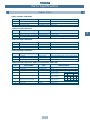
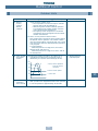
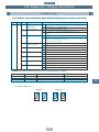
3. Branching joints/headers
Model name
Y-shape branching joint
4-branching header (*3)
8-branching header (*3)
Usage
Appearance
RBM-Y018
Indoor unit capacity code (*1): Total below 6.4
RBM-Y037
Indoor unit capacity code (*1): Total 6.4 or more and below 13.2
(*2)
RBM-Y071
Indoor unit capacity code (*1): Total 13.2 or more and below 25.2
(*2)
RBM-Y129
Indoor unit capacity code (*1): Total 25.2 or more
(*2)
RBM-H4037
Indoor unit capacity code (*1): Total below 13.2
RBM-H4071
Indoor unit capacity code (*1): Total 13.2 or more and below 25.2
Max. 4
branches
RBM-H8037
Indoor unit capacity code (*1): Total below 13.2
RBM-H8071
Indoor unit capacity code (*1): Total 13.2 or more and below 25.2
Max. 8
branches
1 set of 3 types of T-shape joint pipes as described below:
The required quantity is arranged and they are combined at the site.
T-shape branching joint
(For connection of
outdoor unit)
RBM-T129
Connecting pipe
Corresponding dia. (mm).
Qty
Balancing pipe
Ø9.52
1
Piping at liquid side
Ø12.7 to Ø22.2
1
Piping at gas side
Ø22.2 to Ø54.1
1
(*1). Code is determined according to the capacity code of the indoor units connected.
(*2). If the total capacity code value of indoor units exceeds that of outdoor units, apply the
capacity code of outdoor units.
(*3). When using a branch header, indoor units with a maximum of 6.0 capacity code in total
can be connected to each branch.
NOTE: If the length of the gas pipe exceeds 30m from the 1st branching to an indoor unit,
increase the gas pipe size by 1 size, i.e. MM-U140 = Gas Ø22.2, Liquid Ø9.5
5
Summary
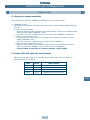
Operating Conditions
2
The units referred to within this manual conform with the protection requirements of
Directives 89/336/EEC Electromagnetic Compatibility and 73/23/EEC Low voltage.
Operating conditions of the unit are as follows:
Outdoor temperature
Room Temperature
Room humidity
-5 ~ 43°C
-15 ~ 21°C
18 ~ 32°C
15 ~ 29°C
<80%
Cooling
Heating
Cooling
Heating
Cooling
Note 1: Cooling capacity is rated at the following temperature conditions:
Indoor air inlet temperature
27°C DB, 19°C WB.
Outdoor air inlet temperature
35°C DB.
Note 2: Heating capacity is rated at the following temperature conditions:
Indoor air inlet temperature
20°C DB.
Outdoor air inlet temperature
7°C DB, 6°C WB.
Note 3: For details about the Outdoor unit, Indoor units or Remote Controller installation
refer to the relevant literature, i.e. Installation Instructions supplied with the units.
Note 4: Operatives handling refrigerants must be suitably qualified in accordance with local
and national codes of practice and statutory requirements.
Note 5: Legislation may regulate the removal of waste refrigerant from the systems. We advise
awareness of any regulations and duty of care. Waste refrigerant must NEVER be
discharged to atmosphere.
Note 6: Electrical work should be in accordance with all relevant codes of practice and should
be carried out by suitably qualified personnel.
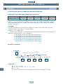
Note 7: Metric/Imperial pipe conversion.
Diameter (mm)
1 5/8
Nominal diameter (inch)
6.4
1
⁄4
9.5
3
⁄8
12.7
1
⁄2
15.9
5
⁄8
Note 8: Within this manual:
ODU = Outdoor Unit
IDU
R/C
= Remote Controller
D.O.L.
INV
= HP Inverter ODU
FIX
DB
= Dry Bulb
WB
Mg-Sw = Magnetic Contactor
IOL
OCR = Over Current Relay
IGBT
Note 9: MPaG ⇒ kgf/cm2G Conversion multiplier
10MPaG = 10.2kgf/cm2G
6
19.0
3
=
=
=
=
=
=
⁄4
22.0
28.6
34.9
41.3
54.1
⁄8
1 ⁄8
1 ⁄8
1 ⁄8
21⁄8
7
1
3
5
Indoor Unit
Direct On-Line compressor
HP Fixed Speed ODU
Wet Bulb
Inner Overload Relay
Inverter Gate Bi-Polar Transistor
Summary
Operating Conditions
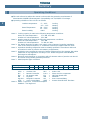
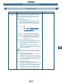
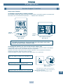
1. Model name
OUTDOOR
2
Modular Multi
MM–A0280HT
A – Outdoor
0280 – 28.0kW (10HP)
0224 – 22.4kW (8HP)
0160 – 16.0kW (6HP)
C – Cooling
H – Heating
T – Inverter
X – Fixed Speed
INDOOR
Modular Multi
MM–TU056
B
–
C (CR) –
K (KR) –
N
–
S (SR) –
SB
–
TU
–
U
–
Built-In Duct Type
Ceiling Type (IR Remote)
High Wall Type (IR Remote)
Carcase Type
Low Wall Type (IR Remote)
Built-In Slim Duct Type
2 Way Cassette Type
4 Way Cassette Type
028
042
056
080
112
140
–
–
–
–
–
–
2.8kW (1HP)
4.2kW (1.5HP)
5.6kW (2HP)
8.0kW (3HP)
11.2kW (4HP)
14.0kW (5HP)
2. Range of combined units
No. of combined units
Capacity range
: 1 to 5 units
: Equivalent to 38.4kW type (14HP) to 128.8kW (46HP)
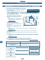
3. Restriction for combination units
(1) The Inverter Unit should have the maximum capacity among all units in
that combination.
(2) The 16.0kW (6HP) fixed-speed unit is available only with the combination of 38.4kW
(14HP) and 60.8kW (22HP). (It cannot be used for any other combination.)
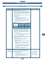
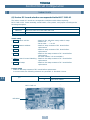
4. Mode priority
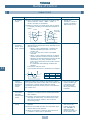
This Outdoor Unit is set to operate with the Heating mode taking precidence. This
precidence can be switched between Heat and Cool mode using the DIP switch 07
on the Outdoor Unit Interface PCB (MCC-1343-01) as follows:
ON
OFF
ON
OFF
Heat Priority (factory set)
7
Cool Priority
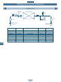
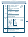
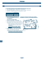
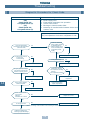
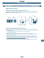
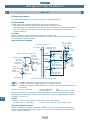
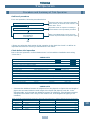
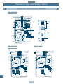
Outline of MMS (Modular Multi System)
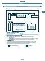
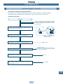
Outline of MMS (Modular Multi System)
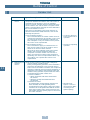
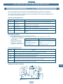
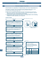
The design of the Toshiba MMS outdoor unit allows for easy unit
maneuvering into any standard lift. Its size also allows it to be easily
installed in limited spaces.
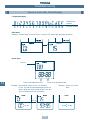
Branching
Combination of line and header branching is highly flexible. This allows
for the shortest design route possible, thereby saving on installation
time and cost. Line/header branching after header branching is only
available with Toshiba’s Multi Modular System.
• Non-polarized control wiring between
outdoor and indoor units
Outdoor unit
Line Branching
Outdoor Unit
Branching joint
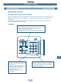
• Wiring diagnosis system
[Example of wiring diagnosis]
Indoor Unit
8F
Header Branching
Outdoor Unit
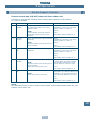
Largest system capacity
Toshiba’s Multi Modular System can be combined up to 128.8kW
(46 HP).
Indoor unit
Use the switches on the microcomputer
PCB of the outdoor unit.
• Detects wiring to the indoor unit b4
which should not be in system A.
• b4 is missing in system B.
Branching
Header
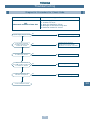
Advanced bus communication system
Wiring between indoor and outdoor unit is a simple 2-wire system.
Communication address is also automatically configured.
A default test mode operation is available.
Self diagnostic system
Comprehensive troubleshooting code enables quick identification of
problems arising.
Piping
System A Outdoor
unit
Wiring
Indoor Unit
System B
Line + Header Branching
Indoor unit
Outdoor
unit
7F
Outdoor
unit
Branching joint
Line Branching after Header Branching
Outdoor Unit
Header
MMS
Only
Branching joint
2F
Indoor Unit
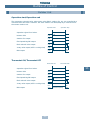
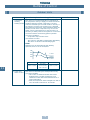
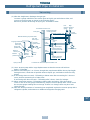
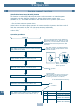
Height difference between indoor
unit and outdoor unit: 30m
Indoor Unit
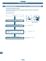
High lift design
Real pipe length of 100m (equivalent length 125m) and vertical lift of
50m is made possible with Toshiba’s Multi Modular System.
Vertical lift between indoor units of 30m is the highest in the market.
This allows for greater flexibility in the location of the system.
Header
Outdoor Unit
Height difference between indoor
unit and outdoor unit: 50m
3
Compact design
Allowable pipe length :
100m real length
(Equivalent to 125m)
Multiple indoor units
Indoor units with different capacities and configurations can be
combined up to 135% of the outdoor unit capacity.
A maximum of 40 indoor units can be combined with the 46 HP
outdoor module.
1st branching
section
Intelligent control
Toshiba’s MMS intelligent controls and modulating valves deliver the
required capacity, according to the load variation from 50% to 100%.
The intelligent controls and modulating valves limit or increase the
cooling/heating capacity dynamically so humidity and temperature
are kept in the comfort zone.
From 1st branching to the
farthest indoor unit: 50m
Outdoor Unit
Header
MMS
Only
1F
Header
Indoor Unit
8
9
3
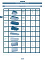
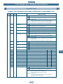
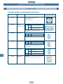
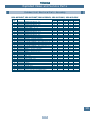
Parts Specifications
Indoor Units
Type
4 Way Cassette
Type ‘U’
4
2 Way Cassette
Type ‘TU’
Built-In Slim
Duct Type ‘SB’
Built-In Duct,
Type ‘B’
Ceiling
Type ‘C’
High Wall
Type ‘K’
Carcase
Type ‘N’
Low Wall
Type ‘S’
Appearance
Model name
Capacity code Cooling Capacity Heating Capacity
(kW)
(kW)
MM-U056
MM-U080
MM-U112
MM-U140
2
3
4
5
5.6
8.0
11.2
14.0
6.4
9.6
12.8
15.8
MM-TU028
MM-TU042
MM-TU056
1
1.5
2
2.8
4.2
5.6
3.2
4.8
6.4
MM-SB028
1
2.8
3.2
MM-B056
MM-B080
MM-B112
MM-B140
2
3
4
5
5.6
8.0
11.2
14.0
6.4
9.6
12.8
15.8
MM-C/CR042
MM-C/CR056
MM-C/CR080
MM-C/CR112
MM-C/CR140
1.5
2
3
4
5
4.2
5.6
8.0
11.2
14.0
4.8
6.4
9.6
12.8
15.8
MM-K/KR042
MM-K/KR056
MM-K/KR080
1.5
2
3
4.2
5.6
8.0
4.8
6.4
9.6
MM-N028
MM-N042
MM-N056
MM-N080
1
1.5
2
3
2.8
4.2
5.6
8.0
3.2
4.8
6.4
9.6
MM-S/SR056
MM-S/SR080
2
3
5.6
8.0
6.4
9.6
10
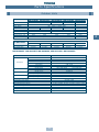
Parts Specifications
Outdoor Units
COMPRESSOR
Model Name
Motor Type
Power Supply
Output
(kΩ)
Pole
(P)
Coil Resistance (W)
Comp. Oil Name
Amount of Oil (ml)
Inner Over-load Relay
4-WAY VALVE
Model Name
Coil Specification
MM-A0280HT MM-A0224HT
MODEL
MM-A0280HX MM-A0224HX MM-A0160HX
MG1450CW-21B
YG1800CW-B1
YG1700CW-B1
3 – Phase induction motor
380 – 415V, 3 – Phase, 50Hz
7.5
7.5
7.5
7.5
2/2 (INV/Fixed)
2/2 (Fixed/Fixed)
1.18/2.25 (INV/Fixed)
2.25/2.25 (Fixed/Fixed)
NISSEKI
RB68AF VG 74
7500
7500
7500
7500
Opens: 115±5 °C
Closes: 93±10°C
MM-A0280HT MM-A0224HT
CHV-0712
AC240V
CHV-0712
AC240V
YG890C-B1
4.1
2
2.250
2000
MODEL
MM-A0280HX MM-A0224HX MM-A0160HX
CHV-0712
AC240V
CHV-0712
AC240V
CHV-0401
AC240V
MM-A0280HT, MM-A0224HT, MM-A0280HX, MM-A0224HX, MM-A0160HX
PARTS NAME
Fan Motor
High Pressure Switch
High Pressure Sensor
Low Pressure Sensor
SPECIFICATION
Model Name
Motor Type
Power Supply
Output (W)
Current (A)
Pole (P)
Model Name
Operating Pressure (kgf/cm2G)
Model Name
Operating Conditions
Model Name
Operating Conditions
Compressor Case Heater
Accumulator Case Heater
Discharge Temperature Sensor
Suction Temperature Sensor
Pulse Modulating Valve
Pulse Modulating Valve (For Cooling Bypass)
2-way Valve
2-way Valve
11
STF-200-350A
1-Phase induction motor
AC 220-240V, 1 Phase, 50Hz
400
4.81~5.89
6
INV=ACB-JB128
FIX=ACB-JA64
Operation: 3.2, Reset 2.55
150NH4-H
0~3.33MPa
150NH4-L
0~0.98MPa
AC240V, 74W
AC240V, 29W
At 50ºC=18.1KΩ, At 100ºC=3.35KΩW,
At 0ºC=34.6KΩ, At 25ºC=10.0KΩ, At 50ºC=3.4KΩ
L12A-03, DC12V
A12A-15, DC12V
VPV-603D, Coil 240V
NEV-202D, Coil 240V
4
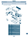
Parts Specifications
Indoor Units
Built-In Duct: MM-B140
No.
1
2
3
PARTS NAME
TYPE
SPECFICATIONS
Fan Motor
STF-200-140-4F
Output (rated) 140W, 4 pole, 200V, 1 Phase 50Hz
Running Capacitor – fan motor EAG40M106UF
AC 400V 10µF
Pulse Motor Valve
EDM-B60YPTF-7B-A Capacity: 60
Built-In Duct: MM-B112
No.
4
1
2
3
PARTS NAME
TYPE
SPECFICATIONS
Fan Motor
STF-200-120-4B
Output (rated) 120W, 4 pole, 200V, 1 Phase 50Hz
Running Capacitor – fan motor EAG40M505UF
AC 400V 5µF
Pulse Motor Valve
EDM-B40YPTR-7B-A Capacity: 40
Built-In Duct: MM-B080
No.
1
2
3
PARTS NAME
TYPE
SPECFICATIONS
Fan Motor
STF-200-100-4B
Output (rated) 100W, 4 pole, 200V, 1 Phase 50Hz
Running Capacitor – fan motor EAG40M505UF
AC 400V 5µF
Pulse Motor Valve
EDM-B40YPTR-7B-A Capacity: 40
Built-In Duct: MM-B056
No.
1
2
3
PARTS NAME
Built-In Duct:
No.
TYPE
MM-B140, MM-B112, MM-B080, MM-B056
PARTS NAME
TYPE
4
5
6
Transformer
Pulse Motor
Pressure Sensor
TT-03-1
EDM-MD12TF-3
150/100NH6-D
7
Sensor for room temperature
TA
8
Sensor for heat exchanger
Tc1
9
Sensor for heat exchanger
Tc2
Control PCB
Power PCB
CM00C02
P00RC01
10
11
SPECFICATIONS
Fan Motor
STF-230-60-4A
Output (rated) 60W, 4 pole, 230V, 1 Phase 50Hz
Running Capacitor – fan motor EEP2G405HQA114 AC 400V 4µF
Pulse Motor Valve
EDM-B40YPTR-7B-A Capacity: 40
SPECFICATIONS
DC 16.3V 0.5A/AC 11.6V 0.15A
DC12V
Power Voltage DC 12V
Maximum input
°C
25
38mA (at 25°C)
kΩ
10
Maximum input
°C -12 0
34mA (at 25°C)
kΩ 62.3 32.8
Maximum input
°C
0
25
26mA (at 25°C)
kΩ 34.6 10
AC 220-240V
AC 220-240V
50
3.45
25 50
10 3.6
50
3.4
Built-In Slim Duct: MM-SB028
No.
PARTS NAME
TYPE
SPECFICATIONS
Output (rated) 34W, 4 pole, 230V, 1 Phase 50Hz
AC 500V 1.0µF
Capacity: 25
DC 16.3V 0.5A/AC 11.6V 0.15A
DC12V
Power Voltage DC 12V
Maximum input
°C
25
50
38mA (at 25°C)
kΩ
10
3.45
Maximum input
°C -12 0
25 50
34mA (at 25°C)
kΩ 62.3 32.8 10 3.6
Maximum input
°C
0
25 50
26mA (at 25°C)
kΩ 34.6 10 3.4
AC 220-240V
AC 220-240V
1
2
3
4
5
6
Fan Motor
Running Capacitor - fan motor
Pulse Motor Valve
Transformer
Pulse Motor
Pressure Sensor
SMF-230-34-4J
EEP2H105HQA105
EDM-B25YPTF-7B-A
TT-03-1
EDM-MD12TF-3
150/100NH6-D
7
Sensor for room temperature
TA
8
Sensor for heat exchanger
Tc1
9
Sensor for heat exchanger
Tc2
Control PCB
Power PCB
CM00C02
P00RC01
10
11
12
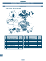
Parts Specifications
Indoor Units
4-Way Cassette: MM-U140
No.
1
2
3
PARTS NAME
TYPE
SPECFICATIONS
Fan Motor
MMF-230-36A
Output (rated) 36W, 6 pole, 230V, 1 Phase 50Hz
Running Capacitor – fan motor EVM45M305UF
AC 450V, 3.0µF
Pulse Motor Valve
EDM-B60YPTF-7B-A Capacity: 60
4-Way Cassette: MM-U112
No.
1
2
3
PARTS NAME
TYPE
SPECFICATIONS
Fan Motor
MMF-230-36A
Output (rated) 36W, 6 pole, 230V, 1 Phase 50Hz
Running Capacitor – fan motor EEP2W255HQA113 AC 450V 2.5µF
Pulse Motor Valve
EDM-B40YPTR-7B-A Capacity: 40
4-Way Cassette: MM-U080
No.
1
2
3
PARTS NAME
TYPE
SPECFICATIONS
Fan Motor
MMF-230-28A
Output (rated) 28W, 6 pole, 230V, 1 Phase 50Hz
Running Capacitor – fan motor EEP2W205HQA107 AC 450V 2.0µF
Pulse Motor Valve
EDM-B40YPTR-7B-A Capacity: 40
4-Way Cassette: MM-U056
No.
1
2
3
PARTS NAME
TYPE
SPECFICATIONS
Fan Motor
MMF-230-28A
Output (rated) 28W, 6 pole, 230V, 1 Phase 50Hz
Running Capacitor – fan motor EEP2H105HQA105 AC 500V 1.0µF
Pulse Motor Valve
EDM-B40YPTR-7B-A Capacity: 40
4-Way Cassette: MM-U140, MM-U112, MM-U080, MM-U056
No.
PARTS NAME
TYPE
4
5
6
Transformer
Pulse Motor
Pressure Sensor
TT-03-1
EDM-MD12TF-3
150/100NH6-D
7
Sensor for room temperature
TA
8
Sensor for heat exchanger
Tc1
9
Sensor for heat exchanger
Tc2
Control PCB
Power PCB
CM00C02
P00RC01
10
11
13
SPECFICATIONS
DC 16.3V 0.5A/AC 11.6V 0.15A
DC12V
Power Voltage DC 12V
Maximum input
°C
25
38mA (at 25°C)
kΩ
10
Maximum input
°C -12 0
34mA (at 25°C)
kΩ 62.3 32.8
Maximum input
°C
0
25
26mA (at 25°C)
kΩ 34.6 10
AC 220-240V
AC 220-240V
50
3.45
25 50
10 3.6
50
3.4
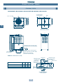
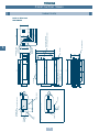
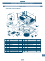
4
Construction Views
Outdoor Units
MM-A0280HT, MM-A0280HX, MM-A0224HT, MM-A0224HX, MM-A0160HX
Grounding part
of bottom plate
755
80
Fixing bolt pitch
630
100
610
100
790
(including fixed leg)
755
Fixing bolt pitch
Fixing bolt pitch
5
Base
80
4-15 x 20 (Slot)
700
990
Base
700
Fixing bolt pitch
Base bolt position
190
245
88
2-60 x 150 Slot
(for transport)
500
(Slot pitch)
235
Refrigerant pipe connecting port
(Gas side) braze connection (ØA)
700
1700
1560
90
750
Refrigerant pipe connecting port
(Liquid side) flare connection (ØB)
Balance pipe connecting
port flare connection (ØC)
Note: All dimensions in (mm)
MM-A0280HT, MM-A0280HX
MM-A0224HT, MM-A0224HX
MM-A0160HX
22.2 12.7
22.2 12.7
22.2 9.52
9.52
9.52
9.52
130
20
65 35
Details of piping
connections
14
170
ØC
mm
64
ØB
mm
115
140
ØA
mm
60
Refrigerant pipe
connecting port
(Gas side)
(knock out)
Balance pipe
connecting port
145
Model
173
125
(knock out)
Refrigerant pipe
connecting port
(Liquid side)
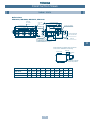
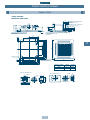
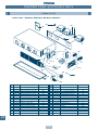
Construction Views
Indoor Units
Built-In Duct
MM-B056, MM-B080, MM-B112, MM-B140
Nx Ø200
Air Outlet
Unit Dimension:800
Hanging Bolt
4-M10
Provided at site
Unit Dimension A
Hanging Bolt Pitch B
Hanging Bolt Pitch:565
6 x Ø4 holes (Ø160)
J=MxK
(H)
Refrigerant Pipe
Connection
(Gas ØF)
Fresh air inlet Ø125
cut-out (other side)
Refrigerant pipe
connection (Liquid ØG)
Filter kit
Drain pipe connection
(inner diameter 32)
(diameter 32 minimal for PVC pipes)
6
Ensure that there is sufficient space around the
indoor unit for installation and servicing
300-400
Inspection
hole
450
200
Indoor unit
450
Provide an inspection
hole in this position
Model
ØG
H
J
K
M
N
700 750 780 12.7
1,000 1,050 1,080 15.9
6.4
9.5
252
252
280
580
280
290
1
2
2
3
MM-B112, B140 1,350 1,400 1,430 19.0
9.5
252
930
310
3
MM-B056
MM-B080
A
B
E
ØF
4
(Unit: mm)
15
158
45
81
333
Shelter board
Air flow
Optional Air Flow (Lower air inlet)
Filter
Filter
Shelter board
342.5
150
150
Unit dimension
Hanging bolt pitch
Air outlet
125
700
800
750
700
450
150
342.5
150
Washable filter
Air inlet
480
265
276
331
364
391
480
Drain pipe connection
(1" BSP threaded connection)
Refrigerant pipe
connection
(Gas Ø12.7)
397
125
Refrigerant pipe
connection
(Liquid Ø6.4)
200
480
700
150
Hanging bolt
pitch
12
35
150
35
Air
flow
75
75
37.5
16
220
500
Unit dimension
200
57
6
Electrical box
(PCB, Transformer and MF Capacitor)
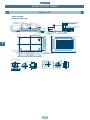
Construction Views
Indoor Units
Built-In Slim Duct
MM-SB028
220
Construction Views
Indoor Units
4-Way Cassette
MM-U056, MM-U080
185
73
140
240
Ceiling
Knockout for side ducts Ø150
(both sides)
138
195
39
20
Wiring connection
Drain pipe connection (Gland plate 3xØ20 holes)
(1" BSP threaded
connection)
30
40
405
400
268
6
940
195
536
800 Hanging bolt pitch
820 External cassette dimension
880 Ceiling opening
940 Panel dimension
138
30
200
Refrigerant pipe connection
(Liquid ØB)
106
259
298
160
106
Refrigerant pipe connection
(Gas ØA)
170
100
80
Fresh air inlet
Condensate pipe 1" BSP
threaded connection
940
Model (MM-)
ØA
ØB
Fresh air inlet duct size
32
Ø100
U056
12.7
12.7
Side outlet duct size
80
10
4-Ø6
45°
6-Ø6
Ø180
130
Ø30
Ø144
Ø97
130
0
Ø18
Ø14
4 Ø130
30 2
80
10
45°
30
45°
17
U080
15.9
9.5
Ø200
620 Hanging bolt pitch
820 External cassette dimension
880 Ceiling opening
940 Panel dimension
Ø150
536
130
30
45°
6
Construction Views
Indoor Units
4-Way Cassette
MM-U112, MM-U140
185
941
106
106
800 Hanging bolt pitch
820 External cassette dimension
880 Ceiling opening
940 Panel dimension
610
605
Ceiling
6
73
140
240
Drain pipe connection
(1" BSP threaded
connection)
Wiring connection
(Gland plate 3xØ20 holes)
940
30
40
20
Ceiling
panel
138
30
202
348
309
210
138
Refrigerant pipe connection
(Liquid side Ø9.5)
30
39
Refrigerant pipe connection
(Gas side Ø19.0)
170
100
80
Fresh air inlet
Side outlet duct size
80
10
Ø30
45°
Ø144
Ø14
4 Ø130
Ø97
4-Ø6
130
1350
6-Ø6
80
10
Ø180
0
Ø18
Ø150
Fresh air inlet duct size
32
Ø100
130
Condensate pipe
1" BSP threaded connection
620 Hanging bolt pitch
820 External cassette dimension
880 Ceiling opening
940 Panel dimension
Ø200
940
30
130
45°
30
30 2
45°
18
45°
6
200
Knockout for side ducts Ø150
(both sides)
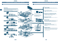
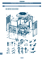
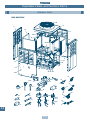
1, 2, 3
Fuse (20 AMP)
Ferrite Core
P
Q
Temperature sensor
FL
Accumulator heater
Transformer
AH
TD1, 2 TE
TK1, 2, 3 TS
Tr
Four-way valve
Two-way valve
Running capacitor
20SF
42, 2
3A, 3B, 3C
RC
SV
High pressure switch
63H 1, 2
Overload relay
Electronic flow control valve
PMV
Inner overload relay
51C
1, 2, 3
1, 2
49C
for compressor
X
Q
P
GRY
X
GRY
Q
GRY
P
GRY
Isolator
Y
Y
RED
WHI
T2
L1 L2
T1
L2
L3
E
N
GRY
T3 E
L3
BLK
Power Supply
50Hz 3N~380/415V
N
N
L1
GRY
BLK
(WHI)
3
3
3
3
1
1
20SF
AH
SV3C
SV3B
SV3A
SV2
SV42
1
(BLU)
1
CN22 CN23
CN04 CN20
CN03 CN19
CN02 CN18
CN01 CN17
Filter Board
MCC - 1366 - 01
WHI
RED
RED
WHI
GRY
Electromagnetic contactor
BLK
Fan motor
4
4
RED
WHI
BLU
5 5
3 3
1 1
3 3
1 1
3 3
1 1
3 3
1 1
BLK
33 33
11 11
(D.O.L.)
CM2
W
V
GRY
(WHI)
(BLU)
(RED)
(BLK)
(BLU)
(BLK)
(BLU)
PMV
3
RED
52C2
S
R
RED
(WHI)
2 1
2 1
(BLU)
2 1
2 1
BLU
V
RED
U
D801
55
55
33
33
1
1
(WHI)
CN308
D802
CN600
(WHI)
6 5 4 3 2 1
6 5 4 3 2 1
1
1
33
33
(BLK)
CN307
55
55
33
33
1 2
3
3
1
1
ON
ON
1
1
SW01
SW07
1 2 3 4
55
55
33
33
1
1
(WHI)
1
1
3
3
1
1
1 2
SW09
ON
SW08
ON
3
3
CN401 CN400
(BLU)
D716 D717 D714 D715
SW02
SW06
1 2 3 4
SW05
SW03
SW04
(RED)
CN402 CN403
CN516
(BLK)
CN100
(WHI)
CN500
(BLU)
CN501
BLK
BLK
BLU
BLU
WHI
BLK
RED
WHI
WHI
RED
1 1
3 3
CN515
BLK
BLK
Tr
BLK
RED
(BLU)
1 1
3 3
1 1
3 3
4 4
3 3
2 2
1 1
4 4
3 3
BLU
BLU
TK2
TK1
Pressure
Sensor
PS
Pressure
Sensor
PD
1. The dashed line indicates wiring on the site.
2.
and indicates terminal blocks and the
numbers within them are terminal numbers.
3.
indicates a printed circuit board.
55
55
1
1
(GRN)
3
3
CN507
(RED)
3
3
(WHI)
(WHI)
2 1
2 1
TK3
TD1
CN505 CN504 CN503 CN502
(BLU)
2 1
2 1
1
1
TS1 TD2
TE
Interface Control PC Board
MCC - 1343 - 03
CN604
(WHI)
1 2
1 2
CN302 CN602 CN601
(RED)
6 5 4 3 2 1
6 5 4 3 2 1
(RED) 1 2 3 4
(RED)
49C2
1 2
1 2
YEL
GRY
(WHI)
CN301
(WHI)
U
CN304
RED
RC
1 1
3 3
CN317
BLU
BLU
CN316
ORG
ORG
CN314
BLU
BLU
CN313
BLU
BLU
BLU 7 7
CN312
BLU
BLU
2 1
(WHI)
2 1
FM
7 7
5 5
4 3 2 1
4 3 2 1
6
6
PMV
2
D
RE
CN300
4 3 2 1
4 3 2 1
PMV
1
6
6
FL1
FL2
CN311
BLU
BLU
GRY
GRY
BLK
BLK
1, 2
BLK
BLK
BLK
52C
Posistor
BLK
FM
RED
WHI
PNK
WHI
BLK
BLK
Part Name
ORG
BLK
BLK
Compressor
RED
BLK
GRY
RED
WHI
BRN
BLK
BLU
ORG
YEL
WHI
BLK
52C1
51C
RED
63H2
BLK
Electrolytic
Capacitor
BLU
RED
ORG
BLK
GRY
RED
FL3
BLK
(WHI)
Reactor
RC
MCC-1343-03
MCC-1366-01
MCC-1342-01
Parts Layout
YEL
T03
T02
PO5
CN16
CN15
CN14
PO4
(WHI)
52C2
FL3
FL2
FL1
Electolytic
Capacitor
WHI
RED
N
51C2
52C1
Posistor
(Inverter)
CM1
BLK
P Q X Y
Power Supply
L1 L2 L3
Reactor
(WHI)
CN07
1 2 3 4 5
1 2 3 4 5
D406
IPDU Board
MCC - 1342 - 01
CN02
CN03
CN01
CN11 CN08 CN09
CN10
CN06
(BLU)
3 3
CN501
1 1
(BLK)
CN04
(BLK)
1 1
3 3
3 3
1 1
BLK
WHI
RED
WHI
1, 2
PUR
WHI
WHI
WHI
BLU
ORG
YEL
WHI
ORG
BLK
RED
WHI
CM
BRN
BLU
GRY
RED
BLU
ORG
YEL
WHI
BLK
GRY
ORG
BLU
WHI
BLK
BLK
19
WHI
U
RED
PINK
RED
BLU
WHI
BLK
1 2
(BLK) 1 2
BLK
BLK
63H1
BLK
49C1
ORG
BL
GRY
ORG
ORG
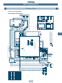
Symbol
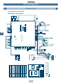
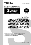
Wiring Diagrams
Outdoor Units
Inverter Unit (10HP, 8HP)
MM-A0280HT, MM-A0224HT
7
1, 2
1, 2
1, 2, 3
49C
51C
PMV
R S T
52C1
U V W
51C1
N
L1 L2 L3
P Q
MCC-1357-01
10,8 HP (Fixed)
1. The dashed line indicates wiring on the site.
2.
and indicates terminal blocks and the
numbers within them are terminal numbers.
3.
indicates a printed circuit board.
R S T
52C2
U V W
51C2
Tr
RC
MCC-1343-03
Parts Layout
Temperature sensor
Ferrite Core
Accumulator heater
Transformer
Tr
AH
Crank case heater
TD1, 2 TE
TK1, 2, 3 TS
Four-way valve
CH
Two-way valve
20SF
SV
Running capacitor
RC
41, 42, 2
3A, 3B, 3C
High pressure switch
63H 1, 2
Electronic flow control valve
Overload relay
Inner overload relay
for compressor
Electromagnetic contactor
1, 2
P
Surge
Absorber
Q
(WHI) 3
3
T2
L1 L2
T1
L2
3
3
1
(BLU)
1
L3
E
T3 E
L3
N
P
P
GRY
Power Supply
50Hz 3N~380/415V
N
Isolator
N
L1
1
1
CN01 CN02
MCC - 1357 - 01
RED
52C
BLK
Compressor
WHI
Fan motor
GRY
FM
GRY
CN03
Q
Q
RED
WHI
CH
BLK
RED
WHI
BLK
Part Name
BLK
4
4
FM
2 1
2 1
7 7
5 5
3 3
1 1
7 7
5 5
3 3
1 1
3 3
1 1
3 3
1 1
3 3
1 1
3 3
1 1
3 3
1 1
CN304
11 11
33 33
CN317
BLU
BLU
CN316
ORG
ORG
CN315
ORG
ORG
CN314
BLU
BLU
CN313
BLU
BLU
CN312
BLU
BLU
BLU
BLU
CN311
BLU
BLU
BLU
BLU
(WHI)
RC
GRY
GRY
20SF
AH
SV3C
SV3B
SV3A
SV2
SV42
SV41
RED
RED
WHI
1, 2
(D.O.L.)
CM2
W
V
U
(WHI)
(BLU)
(RED)
(WHI)
(BLK)
(BLU)
(BLK)
(BLU)
(WHI)
CN300
4 3 2 1
4 3 2 1
6
6
D802
D801
(RED)
CN302
6 5 4 3 2 1
6 5 4 3 2 1
2 1
CN604
(WHI)
1 2
CN601
(BLU)
2 1
2 1
GRY
ORG
63H2
55
55
33
33
1 2 3 4
1 2 3 4
1
1
(WHI)
CN308
49C2
1 2
1 2
33
33
5
5
11
11
(BLK)
CN307
GRY
5
5
3
3
1
3 2 1
ON
1 2
3
3
1
1
11
11
11 2 3 44
11 22 3
3 44
SW04
ON
49C1
1 2
1 2
CN305
3
3
SW01
SW07
1
1
GRY
BL
K
1
1
3
3
1
1
3
3
CN401 CN400
(BLU)
1 2
CM1
(D.O.L.)
GRY
GRY
CN402 CN403
SW09
ON
SW08
(WHI)
1 2 3 4
D717 D714 D715
(RED)
5
5
ON
SW02
SW06
SW03
D716
SW05
1 2 3 4
CN516
(BLK)
CN100
(WHI)
CN500
(BLU)
(RED)
1
1
CN501
3
3
(GRN)
(RED)
3
CN507
(WHI)
2 1
2 1
TK3
TD1
TD2
(WHI)
(BLU)
2 1
2 1
TS
TE
BLK
CN505 CN504 CN503 CN502
CN306
(BLU)
63H1
Interface Control PC Board
MCC - 1343 - 03
(WHI)
CN301
4 3 2 1
4 3 2 1
RED
6
6
(BLK)
CM
52C2
51C2
GRY
Symbol
RED
BLK
RED
PUR
RED
WHI
BRN
BLK
PMV
3
GRY
BLK
BLK
RED
BLU
ORG
YEL
WHI
YEL
ORG
BLK
BLK
ORG
BRN
(RED)
BLU
ORG
YEL
WHI
BLK
WHI
GRY
RED
BLU
ORG
YEL
WHI
BRN
BLK
(RED)
BLK
BLK
WHI
PMV
2
PUR
ORG
(BLK)
BLK
BLK
RED
52C1
51C1
BRN
BLK
BLK
RED
20
BLK
7
BLK
RED
BLK
BLU
TK2
BLU
Tr
BLK
TK1
Pressure
Sensor
PS
Pressure
Sensor
PD
WHI
1 1
3 3
CN515
BLK
BLK
BLU
BLU
WHI
BLK
RED
WHI
(BLU)
1 1
3 3
1 1
3 3
4 4
3 3
2 2
1 1
4 4
3 3
RED
YEL
PMV
1
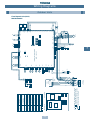
Wiring Diagrams
Outdoor Units
Fixed Speed Unit (10-HP, 8HP)
MM-A0280HX, MM-A0224HX
1
1
1, 3
49C
51C
PMV
R S T
52C1
U V W
51C1
N
L1 L2 L3
P Q
MCC-1357-01
6 HP (Fixed)
1. The dashed line indicates wiring on the site.
2.
and indicates terminal blocks and the
numbers within them are terminal numbers.
3.
indicates a printed circuit board.
Tr
RC
MCC-1343-03
Parts Layout
Ferrite Core
Accumulator heater
Temperature sensor
AH
Transformer
Tr
TD1
TE
TK1, 2, 3 TS
Crank case heater
CH
Two-way valve
Four-way valve
20SF
SV
Running capacitor
RC
41, 2
3A, 3B, 3C
High pressure switch
63H 1
Electronic flow control valve
Overload relay
Inner overload relay
for compressor
Electromagnetic contactor
1
P
3
(WHI) 3
Isolator
Surge
Absorber
Q
1
T2
L1 L2
T1
L2
3
3
L3
E
T3 E
L3
N
P
P
GRY
1
(BLU)
1
Power Supply
50Hz 3N~380/415V
N
N
L1
1
CN01 CN02
MCC - 1357 - 01
RED
52C
BLK
Fan motor
WHI
FM
GRY
Compressor
GRY
CN03
Q
Q
RED
WHI
BLK
CH
BLK
4
4
FM
2 1
2 1
7 7
5 5
3 3
1 1
7 7
5 5
3 3
1 1
3 3
1 1
3 3
1 1
3 3
1 1
3 3
1 1
3 3
1 1
CN304
11 11
33 33
CN317
BLU
BLU
CN316
ORG
ORG
CN315
ORG
ORG
CN314
BLU
BLU
CN313
BLU
BLU
CN312
BLU
BLU
BLU
BLU
CN311
BLU
BLU
(WHI)
RC
GRY
GRY
20SF
AH
SV3C
SV3B
SV3A
SV2
SV41
4 3 2 1
4 3 2 1
RED
(WHI)
(BLU)
(RED)
(WHI)
(BLK)
(BLU)
(BLK)
(BLU)
(WHI)
CN300
BLU
ORG
YEL
WHI
6
6
6
D802
D801
(RED)
CN302
6 5 4 3 2 1
6 5 4 3 2 1
GRY
RED
BLU
ORG
YEL
WHI
2 1
CN604
(WHI)
1 2
CN601
(BLU)
2 1
2 1
5
3
1
5
3
1
(BLU)
5
5
3
3
1
1
3
3
11
11
11 2 3 44
11 22 3
3 44
SW04
ON
(RED)
1 2
1 2
49C1
3
3
SW01
SW07
1
1
GRY
(BLU)
BL
K
1
1
3
3
1
1
3
3
CN401 CN400
1 2
CM1
(D.O.L.)
GRY
GRY
CN402 CN403
CN516
(BLK)
CN100
(WHI)
CN500
(BLU)
(RED)
CN501
(GRN)
CN507
1
1
3
3
TK3
SW09
ON
SW08
ON
1 2
3 2 1
(WHI)
1 2 3 4
D717 D714 D715
CN305
5
5
ON
SW02
SW06
SW03
D716
SW05
1 2 3 4
(WHI)
1
CN502
3
TD1
(WHI)
(BLU)
2 1
2 1
2 1
2 1
TS
BLK
CN505 CN504
CN306
63H1
Interface Control PC Board
MCC - 1343 - 03
4 3 2 1
GRY
Part Name
PUR
1
BLK
BLK
TE
RED
CM
(RED)
BLK
BLK
ORG
BRN
(RED)
Symbol
RED
RED
WHI
BRN
BLK
BLK
BLK
BLK
RED
52C1
51C1
BLK
WHI
PMV
3
WHI
RED
BLK
BLK
21
BLK
RED
BLK
BLU
TK2
BLU
Tr
BLK
TK1
Pressure
Sensor
PS
Pressure
Sensor
PD
WHI
1 1
3 3
CN515
BLK
BLK
BLU
BLU
WHI
BLK
RED
WHI
(BLU)
1 1
3 3
1 1
3 3
4 4
3 3
2 2
1 1
4 4
3 3
RED
YEL
PMV
1
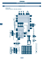
Wiring Diagrams
Outdoor Units
Fixed Speed Unit (6HP)
MM-A0160HX
7
WHI
GRY
FM
GRN/YEL
9 8 7 6 5 4 3 2 1
9 8 7 6 5 4 3 2 1
BRN
9 8 7 6 5 4 3 2 1
9 8 7 6 5 4 3 2 1
BRN
Running Capacitor
Temperature Sensor
Tempterature Sensor
Transformer
Ferrite Core
TC1
TC2
TR
FC
Q
P
C
B
A
WHI
RED
RED
Communication
Remote
Controller
(Optional)
N
L
1. The dashed line indicates wiring on the site.
2.
and indicates terminal blocks and the
numbers within them are terminal numbers.
Temperature Sensor
TA
RY01~RY04 Relay
Pressure Sensor
PS
Pulse Modulating Valve
PMV
RC
Fan Motor
FM
Name
Fuse (PCB)
F
Symbol
Connector Assembly
(Accessory)
Power Supply
220/240
~50Hz
3 3
1 1
CN03
F
9
9
YEL
1 2
1 2
Q
P
C
B
A
RY03
L
5
5
GRY
GRY
1 23
1 23
RY04
3
3
5
5
CN25
3 3
CN02
1 2
1 2
CN101
1
2
3
4
5
6
WHI
BLU
BLU
BLU
BLU
BLU
BLU
6 4 3 1 2 5
6 4 3 1 2 5
PMV
1
2
3
4
5
6
CN25
1
2
3
4
5
6
CN28
5 5
CN10
WHI
BLU 1 1
BLU 2 2
3 3
1 2 3 4 5 6
1 2 3 4 5 6
1
2
3
4
5
6
CN27
1
2
3
4
CN51
1
2
3
4
RED
WHI
BLK
MCC-1355-01
BLK
ORN
1 1
YEL 2 2
BLU
TR
WHI
CN16
1
1
GRN/YEL
CN07
M H
1
1
3
3
RED
CN50
RY01
RY02
UL
7
7
FM
9 8 7 6 5 4 3 2 1
9 8 7 6 5 4 3 2 1
BRN
GRY
BLU
RC
RED
WHI
ORN
BLK
ORN
BLU
YEL
RED
BLK
ORN
YEL
RED
BLK
ORN
BLU
YEL
RED
BLK
ORN
BLU
YEL
RED
BLK
RC
WHI
YEL
ORN
BLU
BRN
RED
22
BLU
ORN
7
WHI
YEL
ORN
BLU
BRN
RED
3
1
1
1
3
3
3
CN26
CN08
5
5
FC
1
1 2
1 2
CN12
WHI
CN11
BLK
1 2
1 2
MCC-1361-01
CN01
CN09
1 2
1 2
YEL
BLK
Increase Fan Speed Option
GRN
RED
WHI
2 2
BLK
1 1
4 4
6 6
CN23
2 2
1 1
YEL
CN20
2 2
1 1
BLU
CN05
2 2
1 1
WHI
CN04
PS
TC1
TC2
TA
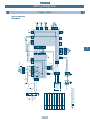
Wiring Diagrams
Indoor Units
Built-In Duct
MM-B140, MM-B112, MM-B080, MM-B056
Fan Motor
Pulse Modulating Valve
Pressure Sensor
Running Capacitor
FM
PMV
PS
RC
Temperature Sensor
Tempterature Sensor
Transformer
Ferrite Core
TC2
TR
FC
Remote
Controller
(Optional)
Communication
WHI
WHI
RED
1. The dashed line indicates wiring on the site.
2.
and indicates terminal blocks and the
numbers within them are terminal numbers.
Temperature Sensor
TA
TC1
RY01~RY04 Relay
Fuse (PCB)
Name
N
L
F
Symbol
Power Supply
220/240
~50Hz
GRN/YEL
Q
P
C
B
A
RC
3 3
1 1
CN03
RED
F
9
9
1 2
1 2
Q
P
C
B
A
RY03
L
5
5
GRY
GRY
3
3
RY04
1
1
CN07
3
3
5
5
CN25
CN02
1 2
1 2
CN101
1
2
3
4
5
6
WHI
BLU
BLU
BLU
BLU
BLU
BLU
6 4 3 1 2 5
6 4 3 1 2 5
PMV
1
2
3
4
5
6
CN25
1
2
3
4
5
6
CN28
5 5
CN10
WHI
BLU 1 1
BLU 2 2
3 3
1 2 3 4 5 6
1 2 3 4 5 6
1
2
3
4
5
6
CN27
1
2
3
4
CN51
1
2
3
4
RED
WHI
BLK
MCC-1355-01
BLK
3 3
1
1
ORN
1 1
YEL 2 2
BLU
TR
WHI
CN16
M H
1
1
3
3
RED
CN50
RY01
RY02
UL
7
7
CN07
ORN
6 5 4 3 2 1
6 5 4 3 2 1
BLK
WHI
YEL
BLU
ORN
RED
BLK
ORN
BLU
RED
WHI
YEL
BLU
GRN/YEL
WHI
YEL
ORN
BLU
BRN
RED
23
WHI
YEL
ORN
BLU
BRN
RED
3
1
1
1
3
3
3
CN26
CN08
5
5
FC
1
1 2
1 2
CN12
WHI
CN11
BLK
1 2
1 2
MCC-1361-01
CN01
CN09
1 2
1 2
YEL
BLK
FM
RED
WHI
2 2
BLK
1 1
4 4
6 6
CN23
2 2
1 1
YEL
GRN
PS
TC1
CN20
2 2
1 1
BLU
TC2
TA
CN05
2 2
1 1
WHI
CN04
Wiring Diagrams
Indoor Units
Built-In Slim Duct
MM-SB028
7
Fuse (PCB)
Fan Motor
Float Switch
Geared Motor
Pulse Modulating Valve
Pressure Sensor
Running Capacitor
FM
FS
GM
PMV
PS
RC
Ferrite Core
FC
Remote
Controller
(Optional)
Communication
WHI
RED
RED
1. The dashed line indicates wiring on the site.
2.
and indicates terminal blocks and the
numbers within them are terminal numbers.
Tempterature Sensor
Transformer
TR
Temperature Sensor
TC1
TC2
Temperature Sensor
TA
RY01~RY07 Relay
Drain Pump
F
Name
N
L
D
Symbol
Power Supply
220/240
~50Hz
GRN/YEL
Q
P
C
B
A
RC
3 3
1 1
CN03
GRY
WHI
F
RED
9
9
1 2
1 2
Q
P
C
B
A
RY03
L
5
5
GRY
GRY
C
B
A
3
3
RY04
1
1
CN07
CN02
Infra-red
Receiver
(IR Model)
3
3
5
5
CN25
1 2
1 2
CN101
BLK
1
2
3
4
5
6
WHI
BLU
BLU
BLU
BLU
BLU
BLU
6 4 3 1 2 5
6 4 3 1 2 5
PMV
1
1
1
1
3
3
DP
GRY PUR
3
1
3
1
BLU BLU
3
3
RY06
1
2
3
4
5
6
CN25
1
2
3
4
5
6
CN28
5 5
CN10
WHI
BLU 1 1
BLU 2 2
3 3
1 2 3 4 5 6
1 2 3 4 5 6
1
2
3
4
5
6
CN27
1
2
3
4
CN51
1
2
3
4
RED
WHI
BLK
MCC-1355-01
3 3
1
1
ORN
1 1
YEL 2 2
BLU
TR
WHI
CN16
M H
1
1
3
3
RED
CN50
RY01
RY02
UL
7
7
YEL
3 2 1
3 2 1
BLU
8 7 6 5
8 7 6 5
ORN
YEL
BLU
ORN
BLK
BLK
GRY
WHI
RED
FM
WHI
YEL
ORN
BLU
BRN
RED
24
BLU
ORN
7
WHI
YEL
ORN
BLU
BRN
RED
GRN/YEL
1
1
1 2
1 2
CN12
CN09
1 2
1 2
CN11
GM
FS
GRN
RED
WHI
2 2
BLK
1 1
4 4
6 6
CN23
2 2
1 1
YEL
CN20
2 2
1 1
BLU
CN05
2 2
1 1
WHI
CN04
MCC-1361-01
CN01
WHI
BLK
RED RED RED
1 2
1 2
1 2 RED
1 2
BLK BLK
BLK BLK
3
3
RY07
1 2
1 2
YEL
BLK
CN26
CN08
5
5
FC
PS
TC1
TC2
TA
Wiring Diagrams
Indoor Units
4-Way Cassette
MM-U140, MM-U112, MM-U080, MM-U056
Refrigerant Piping Systematic Drawings
Inverter Unit (10HP, 8HP)
Model: MM-A0280HT, MM-A0224HT
Propeller fan
M
Sensor
(TE1)
PMV (A)
Fan Motor
Condenser
Condenser
Sensor
(TS)
4-Way valve
Solenoid valve
(SV2)
Pulse motor valve B
(Cooling bypass)
(PMVB)
8
Highpressure
sensor
Sensor
(TK1)
Check joint (Pd)
Strainer
Capillary
Sensor
(TD1)
Compressor
Strainer
Oil tank
Check
valve
Sensor
(TK3)
Check valve
Solenoid
valve
(SV3A)
Compressor
case oil
removal valve
Capillary
Solenoid
valve
(SV42)
HP
Highpressure
SW
Sensor
(TD2)
Packed Service
valve valve
(liquid (gas side)
side)
25
Accumulator
Check
joint (Ps)
Capillary
Lowpressure
sensor
Check
valve
Capillary
Check valve
Packed
valve (oil
balancing
pipe)
Fixed-speed
Capillary
Check valve
HighHP pressure
SW
Sensor
(TK2)
Dryer
(x2)
Oil
Strainer
separator
Inverter
Strainer
Liquid
tank
Solenoid valve
(SV3C)
Check
valve
Solenoid
valve
(SV3B)
Strainer
Refrigerant Piping Systematic Drawings
Fixed Speed Unit (10HP, 8HP)
Model: MM-A0280HX, MM-A0224HX
Propeller fan
M
Sensor
(TE1)
PMV (A)
Fan Motor
Condenser
Condenser
Capillary
Sensor
(TS)
4-Way valve
Solenoid valve
(SV2)
Pulse motor valve B
(Cooling bypass) (PMVB)
8
Sensor
(TK1)
Highpressure
sensor
Check joint (Pd)
Strainer Capillary
Solenoid valve
(SV3C)
Strainer
Check
valve
Liquid
tank
Oil
separator
Check
valve
Capillary
Sensor
(TD1)
Sensor
(TK2)
Dryer
(x2)
Oil tank
Check
valve
Sensor
(TK3)
Check valve
Solenoid
valve
(SV3A)
Compressor
case oil
removal valve
Solenoid
valve
(SV42)
HP
Highpressure
SW
Sensor
(TD2)
Packed Service
valve valve
(liquid (gas side)
side)
26
Accumulator
Check
joint (Ps)
Capillary
Lowpressure
sensor
Check
valve
Capillary
Check valve
Packed
valve (oil
balancing
pipe)
Fixed-speed
Compressor
Strainer
Fixed-speed
Strainer
Capillary
HighHP pressure
SW
Solenoid
valve
(SV41)
Check
valve
Solenoid
valve
(SV3B)
Strainer
Refrigerant Piping Systematic Drawings
Fixed Speed Unit (6HP)
Model: MM-A0160HX
Propeller fan
Fan Motor
M
Condenser
PMV (A)
Condenser
Sensor (TE1)
Capillary
Sensor
(TS)
4-Way valve
Solenoid valve
(SV2)
Pulse motor valve B
(Cooling bypass)
(PMVB)
8
Highpressure
sensor
Sensor
(TK1)
Solenoid valve
(SV3C)
Check joint (Pd)
Strainer
Liquid
tank
Strainer
Oil
separator
Capillary
Capillary
Compressor
Strainer
Fixed-speed
Strainer
Check valve
Sensor
(TK2)
Dryer
(x2)
Oil tank
Check
valve
Sensor
(TK3)
Check valve
Solenoid
valve
(SV3A)
Compressor
case oil
removal valve
Solenoid
valve
(SV41)
HP
Highpressure
SW
Sensor
(TD1)
Packed Service
valve valve
(liquid (gas side)
side)
27
Accumulator
Check
joint (Ps)
Capillary
Lowpressure
sensor
Check
valve
Capillary
Check valve
Packed
valve (oil
balancing
pipe)
Capillary
Check
valve
Solenoid
valve
(SV3B)
Strainer
Pressure
sensor
Check
joint
TC1
Pressure
sensor
Check
joint
TC1
Pressure
sensor
Check
joint
TC1
TA
(Ambient
sensor)
Evaporator
(Indoor unit 3)
TA
(Ambient
sensor)
Evaporator
PMV
TC2
TC2
Packed
valve (oil
balancing
pipe)
Packed
valve
(liquid
side)
Dryer
(x2)
Liquid
tank
PMV (A)
Capillary
Capillary
Service
valve
(gas side)
Check valve
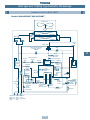
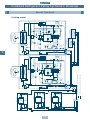
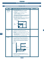
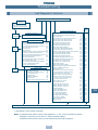
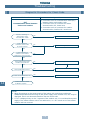
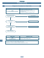
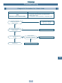
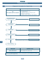
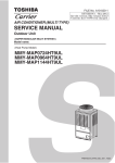
(Dotted line) Evaporating gas refrigerant (Low-pressure gas)
Check joint (Pd)
Compressor
Check
valve
HighHP pressure
SW
Compressor
case oil
removal valve
(TK3)
Check
Sensor
valve
Check
valve
Solenoid
valve
(SV3A)
Oil tank
Sensor
(TK2)
Sensor
(TD1)
Solenoid valve
Sensor
(SV3C)
(TK1)
Strainer
Highpressure
sensor
Solenoid valve
(SV2)
Check
valve
Capillary
Lowpressure
sensor
Sensor
(TD2)
Highpressure
SW
HP
Solenoid
valve
(SV42)
Strainer Capillary
Oil
separator
4-Way valve
Air heat exchanger at outdoor side
Pulse motor valve B
(Cooling bypass)
(PMVB)
Strainer
Fan Motor
(Right side)
M
Sensor Air heat exchanger at outdoor side
(Left side)
(TE1)
(Solid line) High-pressure gas or compressed liquid refrigerant
Strainer
PMV
TC2
Strainer
PMV
Strainer
(Indoor unit 2)
TA
(Ambient
sensor)
Air heat
exchanger
at indoor
side
Strainer
Evaporator
Inverter
(Indoor unit 1)
Check
valve
Check
joint (Ps)
Strainer
Solenoid
valve
(SV3B)
Liquid
tank
Packed
valve
(liquid
side)
Dryer
(x2)
Packed
valve (oil
balancing
pipe)
Capillary
Accumulator
Sensor (TS)
PMV (A)
Strainer
Propeller fan
Fixed-speed
28
Capillary
Lowpressure
sensor
Highpressure
SW
Sensor
(TD2)
HP
Solenoid
valve
(SV42)
Packed
valve (oil
balancing
pipe)
Packed
valve Service
(liquid valve
side) (gas side)
Service
Slave unit 3 (Fixed-speed)
valve
(gas side) Packed
Packed
Service
MM-A0280HX
valve (oil valve valve
balancing (liquid (gas side) Slave unit 4 (Fixed-speed)
side)
pipe)
MM-A0280HX
Check valve
Compressor
HighHP pressure
SW
Compressor
Check
case oil
removal valve valve
(TK3)
Check joint (Pd)
Highpressure
sensor
Strainer Capillary
Oil
separator
Check Solenoid
valve
valve
(SV41)
4-Way valve
Condenser
Solenoid valve
(SV2)
Fan Motor
Condenser
Check
valve
Check
Sensor
valve
Sensor
(TD1)
Check
valve
Solenoid
valve
(SV3A)
Oil tank
Sensor
(TK2)
Strainer
Capillary
Capillary
Sensor
(TK1)
Solenoid valve
(SV3C)
Strainer
Pulse motor valve B
(Cooling bypass)
(PMVB)
Capillary
Sensor
(TE1)
M
Propeller fan
MM-A0280HX
Slave unit 2 (Fixed-speed)
Fixed-speed
9
Fixed-speed
MM-A0280HT
Master unit 1 (Inverter)
Check
valve
Check
joint (Ps)
Strainer
Solenoid
valve
(SV3B)
Capillary
Accumulator
Sensor (TS)
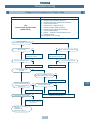
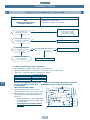
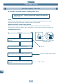
Combined Refrigerant Piping Systematic Drawings
Normal Operation
(Cooling mode)
Pressure
sensor
Check
joint
TC1
Pressure
sensor
Check
joint
TC1
Pressure
sensor
Check
joint
TC1
TA
(Ambient
sensor)
Evaporator
(Indoor unit 3)
TA
(Ambient
sensor)
Evaporator
PMV
TC2
Strainer
PMV
TC2
Strainer
PMV
Strainer
(Indoor unit 2)
TA
(Ambient
sensor)
TC2
Packed
valve
(liquid
side)
Service
valve
(gas side)
Check
valve
Capillary
Lowpressure
sensor
Sensor
(TD2)
Highpressure
SW
HP
Solenoid
valve
(SV42)
Capillary
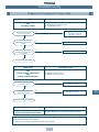
Service valves closed fully at liquid and gas side.
Check valve
Compressor
Highpressure
sensor
Check joint (Pd)
Check
valve
HighHP pressure
SW
Oil
separator
Compressor
case oil
removal valve
(TK3)
Check
Sensor
valve
Check
valve
Solenoid
valve
(SV3A)
Oil tank
Sensor
(TK2)
Strainer
Capillary
Sensor
(TD1)
Solenoid valve
Sensor
(SV3C)
(TK1)
Strainer
Capillary
Condenser
Solenoid valve
(SV2)
Fan Motor
Condenser
M
4-way valve
Pulse motor valve B
(Cooling bypass)
(PMVB)
Sensor
(TE1)
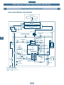
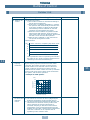
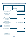
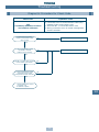
(Dotted line) Evaporating gas refrigerant (Low-pressure gas)
(Solid line) High-pressure gas or compressed liquid refrigerant
Packed
valve (oil
balancing
pipe)
Dryer
(x2)
Liquid
tank
PMV (A)
Failure
Inverter
Evaporator
Fixed-speed
(Indoor unit 1)
Strainer
Propeller fan
Check
valve
Check
joint (Ps)
Strainer
Solenoid
valve
(SV3B)
Liquid
tank
Packed
valve
(liquid
side)
Dryer
(x2)
Packed
valve (oil
balancing
pipe)
Capillary
Accumulator
Sensor (TS)
PMV (A)
Compressor
HighHP pressure
SW
Check
valve
Capillary
Lowpressure
sensor
HP
Highpressure
SW
Sensor
(TD2)
Solenoid
valve
(SV42)
Packed
valve (oil
balancing
pipe)
Packed
valve Service
(liquid valve
side) (gas side)
Service
Slave unit 3 (Fixed-speed)
valve
(gas side) Packed
Packed
MM-A0280HX
valve (oil valve Service
balancing (liquid valve
Slave unit 4 (Fixed-speed)
side) (gas side)
pipe)
MM-A0280HX
Check valve
Highpressure
sensor
Check joint (Pd)
Strainer Capillary
Oil
separator
Check
Solenoid
valve
valve
(SV41)
Compressor
case oil
removal valve
(TK3)
Check
valve
Check
Sensor
valve
Sensor
(TD1)
Check
valve
Solenoid
valve
(SV3A)
Oil tank
Sensor
(TK2)
Strainer
Capillary
Capillary
Sensor
(TK1)
4-Way valve
Condenser
Solenoid valve
(SV2)
Fan Motor
Condenser
M
Propeller fan
Solenoid valve
(SV3C)
Strainer
Pulse motor valve B
(Cooling bypass)
(PMVB)
Capillary
Sensor
(TE1)
Temporal setup
master unit
in emergency
Strainer
MM-A0280HX
Slave unit 2 (Fixed-speed)
Fixed-speed
29
Fixed-speed
MM-A0280HT
Master unit 1 (Inverter)
Check
valve
Check
joint
(Ps)
Strainer
Solenoid
valve
(SV3B)
Capillary
Accumulator
Sensor (TS)
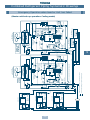
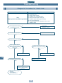
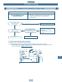
Combined Refrigerant Piping Systematic Drawings
Emergency Operation when Inverter Unit has Failed
(Master unit back-up operation: Cooling mode)
9
Pressure
sensor
Check
joint
TC1
Pressure
sensor
Check
joint
TC1
Pressure
sensor
Check
joint
TA
(Ambient
sensor)
Evaporator
(Indoor unit 3)
TA
(Ambient
sensor)
Evaporator
PMV
Packed
valve (oil
balancing
pipe)
Packed
valve
(liquid
side)
Dryer
(x2)
Liquid
tank
PMV (A)
Check
valve
Service
valve
(gas side)
Check valve
(Dotted line) Evaporating gas refrigerant (Low-pressure gas)
Check joint (Pd)
Compressor
Check
valve
HighHP pressure
SW
Capillary
Check
valve
Check
joint (Ps)
Strainer
Solenoid
valve
(SV3B)
Capillary
Accumulator
Sensor (TS)
Service valve opened fully at balancing pipe.
Check
valve
Lowpressure
sensor
Sensor
(TD2)
Highpressure
SW
HP
Solenoid
valve
(SV42)
Strainer Capillary
Oil
separator
Compressor
case oil
removal valve
Sensor
(TK3)
Sensor
(TD1)
Check
valve
Solenoid
valve
(SV3A)
Oil tank
Sensor
(TK2)
Strainer
Capillary
Capillary
Solenoid valve
Sensor
(SV3C)
(TK1)
Strainer
Highpressure
sensor
Solenoid valve
(SV2)
Fan Motor
4-way valve
Condenser
Condenser
Pulse motor valve B
(Cooling bypass)
(PMVB)
Sensor
(TE1)
(Solid line) High-pressure gas or compressed liquid refrigerant
Strainer
PMV
TC2
Strainer
PMV
TC2
Strainer
(Indoor unit 2)
TA
(Ambient
sensor)
M
Inverter
TC2
Fixed-speed
TC1
PMV (A)
Failure
Packed
valve (oil
balancing
pipe)
Packed
valve
(liquid
side)
Dryer
(x2)
Liquid
tank
Check
valve
Check
joint (Ps)
Check
valve
Capillary
Lowpressure
sensor
Highpressure
SW
Sensor
(TD2)
HP
Solenoid
valve
(SV42)
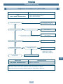
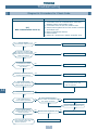
Service valves closed fully at
Compressor
HighHP pressure
SW
MM-A0280HX
Service
liquid and gas sides.
Slave unit 3 (Fixed-speed)
valve
(gas side)
Packed
Packed
MM-A0280HX
valve (oil valve Service
balancing (liquid valve
Slave unit 4 (Fixed-speed)
side) (gas side)
pipe)
Packed
Packed
valve (oil valve Service
balancing (liquid valve
side) (gas side)
pipe)
Check valve
Highpressure
sensor
Check joint (Pd)
Strainer Capillary
Oil
separator
Check
Solenoid
valve
valve
(SV41)
Compressor
case oil
removal valve
Check Sensor
valve
(TK3)
Sensor
(TD1)
Check
valve
Solenoid
valve
(SV3A)
Oil tank
Sensor
(TK2)
Strainer
Capillary
Check
valve
4-Way valve
Condenser
Solenoid valve
(SV2)
Fan Motor
Condenser
Solenoid valve
(SV3C)
Strainer
Capillary
Sensor
(TK1)
Pulse motor valve B
(Cooling bypass)
(PMVB)
Capillary
Sensor
(TE1)
M
Propeller fan
Strainer
Evaporator
MM-A0280HX
Slave unit 2 (Fixed-speed)
Propeller fan
Fixed-speed
30
Fixed-speed
(Indoor unit 1)
Strainer
9
MM-A0280HT
Master unit 1 (Inverter)
Strainer
Solenoid
valve
(SV3B)
Capillary
Accumulator
Sensor (TS)
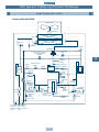
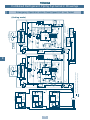
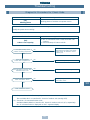
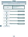
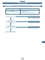
Combined Refrigerant Piping Systematic Drawings
Emergency Operation when Fixed-Speed Unit has Failed
(Cooling mode)
Pressure
sensor
Check
joint
TC1
Pressure
sensor
Check
joint
TC1
Pressure
sensor
Check
joint
TC1
TA
(Ambient
sensor)
Evaporator
(Indoor unit 3)
TA
(Ambient
sensor)
Evaporator
PMV
Packed
valve (oil
balancing
pipe)
Packed
valve
(liquid
side)
Dryer
(x2)
Liquid
tank
PMV (A)
Check
valve
Service
valve
(gas side)
Check valve
Check
valve
Solenoid
valve
(SV3A)
Oil tank
Sensor
(TK2)
Strainer
Capillary
(Dotted line) Evaporating gas refrigerant (Low-pressure gas)
Check joint (Pd)
Highpressure
sensor
Solenoid valve
(SV2)
Compressor
Check
valve
HighHP pressure
SW
Capillary
Check
valve
Check
joint
(Ps)
Strainer
Solenoid
valve
(SV3B)
Capillary
Accumulator
Sensor (TS)
Service valve fully closed at liquid side.
Service valve fully opened at balancing pipe.
Check
valve
Lowpressure
sensor
Sensor
(TD2)
Highpressure
SW
HP
Solenoid
valve
(SV42)
Oil
Strainer Capillary
separator
Compressor
case oil
removal valve
Sensor
(TK3)
Sensor
(TD1)
Solenoid valve
Sensor
(SV3C)
(TK1)
Strainer
Capillary
Condenser
Condenser
Fan Motor
4-way valve
Pulse motor valve B
(Cooling bypass)
(PMVB)
Sensor
(TE1)
(Solid line) High-pressure gas or compressed liquid refrigerant
Strainer
PMV
TC2
Strainer
PMV
TC2
Strainer
(Indoor unit 2)
TA
(Ambient
sensor)
TC2
M
Inverter
Evaporator
Fixed-speed
(Indoor unit 1)
Strainer
Propeller fan
Dryer
(x2)
Liquid
tank
PMV (A)
Strainer
Check
valve
Packed
valve (oil
balancing
pipe)
Compressor
HighHP pressure
SW
Packed
valve Service
(liquid valve
side) (gas side)
MM-A0280HX
Slave unit 3 (Fixed-speed)
Check valve
Highpressure
sensor
Check joint (Pd)
Packed
valve (oil
balancing
pipe)
Check
valve
Check
joint
(Ps)
Strainer
Solenoid
valve
(SV3B)
Capillary
Accumulator
Sensor (TS)
Service valve fully closed at gas
side ➝ Fully closed approx.
10min after operation start
Capillary
Packed
valve Service
(liquid valve
side) (gas side)
MM-A0280HX
Slave unit 4 (Fixed-speed)
Check
valve
Lowpressure
sensor
Sensor
(TD2)
Highpressure
SW
HP
Solenoid
valve
(SV42)
Strainer Capillary
Oil
separator
Check Solenoid
valve
valve
(SV41)
4-Way valve
Condenser
Solenoid valve
(SV2)
Fan Motor
Compressor
case oil
removal valve
(TK3)
Check Sensor
valve
Sensor
(TD1)
Check
valve
Solenoid
valve
(SV3A)
Oil tank
Sensor
(TK2)
Strainer
Capillary
Capillary
Sensor
(TK1)
M
Condenser
Solenoid valve
(SV3C)
Strainer
Pulse motor valve B
(Cooling bypass)
(PMVB)
Capillary
Sensor
(TE1)
Failure
Propeller fan
MM-A0280HX
Slave unit 2 (Fixed-speed)
Fixed-speed
31
Fixed-speed
MM-A0280HT
Master unit 1 (Inverter)
Combined Refrigerant Piping Systematic Drawings
Recovery of Refrigerant in Failed Outdoor Unit
(Normal outdoor unit refrigerant recovery)
9
Refrigeration Cycle Schematic
Indoor Units
Distributor
strainer
PMV (D)
Heat exchanger
TC2
Check
joint
TC1
Liquid
sensor
Gas
sensor
Capillary
tube (B)
Pressure
sensor
Strainer
Strainer
Refrigerant Pipe
(liquid) (A)
Model
MM-B056
MM-B080
MM-B112
MM-B140
MM-SB028
MM-U056
MM-U080
MM-U112
MM-U140
Refrigerant
Pipe (Gas) (C)
Ø(A) mm
6.4
9.5
9.5
9.5
6.4
6.4
9.5
9.5
9.5
(3/8”)
(3/8”)
(3/8”)
(3/8”)
(3/8”)
(3/8”)
(3/8”)
(3/8”)
(3/8”)
Capillary Ø(B) mm
Ø1.7x150Lx3
Ø2.6x200Lx4, Ø2.6x400Lx2
Ø2.2x200Lx6
Ø2.2x200Lx6
Ø1.7x250Lx2
Ø2.0x200Lx3
2.6x(150Lx2), (200Lx3), (400Lx1)
2.6x(200Lx6), (300Lx2), (500Lx2)
2.6x(200Lx6), (300Lx2),(500Lx2)
10
32
Ø(C) mm
12.7
15.9
19.0
19.0
12.7
12.7
15.9
19.0
19.0
(1/2”)
(5/8”)
(3/4”)
(3/4”)
(1/2”)
(1/2”)
(5/8”)
(3/4”)
(3/4”)
PMV (D) Code
40
40
40
60
25
40
40
40
60
Outline of Control
Outdoor Unit
Operation start/Operation end
The compressor, solenoid valve, pulse motor valve (PMV), outdoor fan, etc. are controlled by a
command from the indoor controller. The slave outdoor unit starts/stops by a command from
the master outdoor unit.
Operation start
Operation stop
Operation signal from indoor
ON
Inverter drive
OFF
Outdoor fan output
OFF
Fixed-speed Mg-SW output
OFF
(By command from indoor)
Each solenoid valve output
OFF
ON or OFF
4-way valve output (OFF in cooling time)
OFF
PMV output
Full
close
ON
ON or OFF
2 minutes
30 seconds
ON
Specified opening
Full
close
Thermostat ON/Thermostat OFF
Thermostat ON
Thermostat OFF
11
Operation signal from indoor
ON
Inverter drive
OFF
Outdoor fan output
OFF
Fixed-speed Mg-SW output
OFF
(By command from indoor)
Each solenoid valve output
OFF
ON or OFF
ON
ON or OFF
2 minutes
30 seconds
4-way valve output (OFF in cooling time)
ON
PMV output
Full
close
33
Specified opening
Full
close
Outline of Control
Outdoor Unit
Item
1a. Electronic
expansion
valve (PMV)
control
Operation explanation and applied data, etc.
(1) PMV A control (PMV x 2)
1) The PMV (pulse motor valve) is controlled
between 100 ~ 1000 pulses during the
operation.
2) The PMV is fully open during the cooling
operation (PMV A1 = 500 pulses,
PMV A2 = 500 pulses).
3) During the heating operation, the opening rate is
determined by the temperature which the TS/TD
sensor detects and the pressure rate which PS
detects (Super heat control).
4) The PMV is fully open when the thermostat is off,
when the operation is switched off or when the
operation is ceased under abnormal
circumstances.
1000
PMV A2
PMV
opening
rate
550
500
100
50
PMV A1
Min.
Max.
Mid.
1b. Pulse motor
valve (PMV)
control
(1) PMV B control
The purpose of PMV B control is to control the liquid
refrigerant bypass by limiting discharge
temperature or compressor internal temperature
increase.
1) Opening is controlled with pulses from 0 ~ 500.
2) PMV opening is controlled with temp. detected
by TS/TD sensors.
3) PMV openings are fully closed during thermostatOFF, operation stop, and emergency stop.
2a. Outdoor fan
control
(1) Cooling fan control
1) In a specified time when cooling operation is
activated, the master outdoor unit controls the
outdoor fan speed (no. of fan driving waves) by Pd
pressure. The slave outdoor unit controls the
outdoor fan speed with temperature detected by
TE sensor.
11
Pd pressure
(kgf/cm2G) 22
[+1 wave/20 sec ]
From 2 waves to
Max. no. of waves
21
19
18
17
[ 16Max.
waves ]
[Hold ]
[+1 wave/20 sec ]
From 1 wave to
(Up to 5 waves)
Max. no. of waves
16
15
14
13
12
11
*
[-1 wave/20 sec ]
In up time:From 0 wave to 1 wave
In down time:
From 15 waves to 1 wave
Interval
control
]:
[[0[1 wave
wave ]:
180 sec
30 sec
]
PD pressure is maintained between 14.5 ~ 18
kgf/cm2G by the cooling fan control. The no. of
waves can be controlled between 0 wave (STOP) to
16 waves (all waves).
34
Remarks
Outline of Control
Outdoor Unit
Item
Operation explanation and applied data, etc.
2b. Outdoor fan
control
(1) Heating fan control
1) The number of waves is controlled according to
the TE sensor temperature.
2) If TE >20°C is constantly detected for 5 minutes,
the operation will automatically shut down. This
is the same condition as when the thermostat
automatically becomes switched off, thus the
operation will automatically start again.
3) When the above condition (2) persists and the
high pressure SW operates, check the suction
area of the indoor unit for blockages. Ensure that
the filter is clean and start the operation.
4) After the fan is switched on, this control does
not operate during defrost mode.
Remarks
TE temperature
(°C)
A zone: minimum, compulsory stop timer count
20
B zone: 2/20 seconds (down to the minimum)
6
C zone: 1/20 seconds (down to the minimum)
4
D zone: hold (maintain the current rate)
2
E zone: +1/20 seconds (up to the maximum)
1
F zone: Maximum revolutions number (16)
Fixed speed/slave units not operating will maintain
the ODU fan at 1 wave to prevent refrigerant from
remaining in the ODU Heat Exchanger.
11
3. Capacity
calculation
By the capacity request command from the indoor
controller, the inverter operation command of the
master outdoor unit, ON/OFF control of the fixedspeed compressor and the slave outdoor unit are
determined. The master outdoor unit sets up activation
priority order of the slave outdoor units connected to
the system, and starts the operation.
<Example of 30HP system>
Requested HP
(HP)
30
25
Inverter
Fixed
20
15
10
5
1
4. Oil level valve
detection
control
5 10 15 20 25 30 (HP)
Operation capacity
1) The volume of oil in the oil tank is judged by the
detection temperature of TK1 and TK2 sensors.
2) The present temperature detected by TK1,TK2 and
TK3 sensors are stored in memory as the initial
value, and then the solenoid valve SV3C is
activated. Sampling of TK1,TK2 and TK3 sensor
temperature occurs and the temperature change
between TK1 and TK2 is judged. If the judgement is
such that a reduction in oil is present the oil
equalizing control function starts.
35
11
Outline of Control
Outdoor Unit
Item
Operation explanation and applied data, etc.
5. Oil equalizing
control
This control is to prevent oil reduction in the
compressor between the outdoor units. This control is
classified into two functions, one is an individual
control in normal operation which is performed by the
master outdoor unit, and the other is a system control
which is executed when shortage has been detected in
the oil level detection control.
This control is executed by open/close operation of
solenoid valves SV3A, SV3B, and SV3C, and has the
following two patterns.
6. Refrigerant/Oil
recovery
control
11
Remarks
(1) Oil equalizing control 1
This is executed when the master outdoor unit has
continuously operated for 30 minutes or more, and
the result of the oil level detection judgment has
been adequate. If only one outdoor unit is present
this control is not implemented.
• Controls to divert oil
to the inverter unit in
operation.
(2) Oil equalizing control 2
This is executed to supply oil collected in the oil
tank of each outdoor unit to the outdoor unit of
which the oil level has been reduced.
When the oil level judgment result of the master
outdoor unit has been insufficient while the
compressor of master outdoor unit was ON, or
when one of the slave outdoor units required oil
equalizing, this control is implemented. When only
one outdoor unit is present this control is not
implemented.
• Normal oil equalizing
operation.
(1) Oil recovery control in cooling mode, Refrigerant
recovery control in heating mode
During cooling/heating operation, this is executed to
recover the oil/refrigerant in gas crossover pipes or
indoor units to the outdoor unit when, the compressor
operation is reduced, this also prevents stagnation of
refrigerant in the outdoor heat exchanger while low
ambient cooling operation is performed. This control
is managed by the master outdoor unit.
1) Control conditions
• When compressor-ON status continued for
60 minutes.
• When the cooling thermostat-OFF timer
has finished.
2) Contents of control
60 minutes after cooling/heating operation has
been activated, the cooling/heating indoor
oil/refrigerant recovery signal is sent to the indoor
controller. The cooling thermostat-ON 60 minutes
timer starts counting again. At the same time, the
indoor PMV minimum opening signal is also sent to
the indoor controller.
36
• Recovery time:
Approx. 2 min to 6
min though it differs
according to the
system capacity.
Outline of Control
Outdoor Unit
Item
7. Release valve
control
Operation explanation and applied data, etc.
Remarks
(1) SV2 gas balance control
This control is executed to balance the gas by
opening SV2 while the compressor is off, in order to
decrease the activation load in the next compressorON time. This control is individually executed by the
master outdoor unit and each slave outdoor unit.
1) Control conditions
When the compressor is switched from ON to OFF
operation.
2) Contents of control
• The control point is exchanged by P
(Pd pressure - Ps pressure) immediately before
the compressor stops.
• When P ≥ P1, SV2 is opened. After SV2 has
been opened, SV2 is turned off when P<P2.
• When P<P1, SV2 is closed.
<Table 7a>
kgf/cm2G
Cooling
Pd pressure
control point
P1, P2
Master outdoor
compressor OFF
Master outdoor
compressor ON
P1
P2
P1
P2
In case of master
13
11
—
—
In case of slave
13
11
5
4
(2) SV2 low pressure release control
This control is to prevent pressure drop during
transient operation. This control is individually
executed by the master outdoor unit and each slave
outdoor unit. This control is executed as necessary
except during stop time and thermostat-OFF time.
1) Contents of control
• SV2 is opened when Ps pressure>0.8 kgf/cm2G
• SV2 is closed when Ps pressure>1.2 kgf/cm2G
11
(3) SV2 compressor case bypass control
This control is to prevent oil dilution. This control is
individually executed by the master outdoor unit and
each slave outdoor unit.
This control is executed during compressor-ON
(except during oil level detection control).
1) Contents of control
SV2 is opened when the following conditions are
satisfied.
• Compressor status changes from OFF to ON.
• Oil recovery control is performed in cooling
mode.
• SV2 is opened when TK3 sensor detects 2°C or
lower, and closed when TK3 sensor detects
5°C or higher temperature during compressorON time.
• No. of outdoor fan waves is 3 waves or less
during cooling compressor-ON.
8. Fixed-speed
compressor
high pressure
release control
This control is to stop the fixed-speed compressor of
each outdoor unit according to Pd pressure value. This
control is individually executed by the master outdoor
unit and each slave outdoor unit.
1) Contents of control
• The fixed-speed compressor stops when Pd
pressure is over P1 (Table 7a).
• Sets the fixed-speed compressor reactivation
time for 10 minutes, and the control
finishes.
37
• No. 2 compressor
stops with Pd ≥,
P1 = 26.5 kgf/cm2G
• No. 1 compressor
stops with Pd ≥ ,
P1 = 27.5 kgf/cm2G
Outline of Control
Outdoor Units
Item
Operation explanation and applied data, etc.
9. Compressor
winding
heating control
This control is to prevent stagnation of refrigerant in
the compressor case by a supply of current to heat the
windings while the inverter compressor is off. This
control is executed by the inverter outdoor unit only. If
the supply of current is not turned on for a specified
time before trial operation, when installation work has
finished, a fault of the compressor may occur. If the
power source is interrupted for a period of time it is
necessary to switch power to the system for a minimum
of 24 hours before commencing system operation
(1) Control conditions
Compressor stops and TD < 35°C.
(2) Contents of control
This control is executed by temperature detected by
TK3 sensor as shown in the following figure.
NOTE:
Switching may be heard during heat winding
operation, but it is not an error/fault.
TK3
40°C
C zone
34°C
B zone
25°C
A zone
11
10. Crank case
heater control
A zone
B zone
C zone
Continuous
switch-on power
Intermittent
switch-on power
ON: 10 minutes
OFF: 5 minutes
No
switch-on power
This control is executed by the fixed-speed unit only.
(1) Control contents
• This control is switched off when TK3 sensor
detected 40°C or higher temperature, and
switched on when TK3 sensor detected 35°C or
lower temperature.
• After the compressor status changed from OFF to
ON, ON status continues for 10 minutes.
38
Remarks
Outline of Control
Outdoor Units
Item
11. IPDU (Inverter)
control
Operation explanation and applied data, etc.
Remarks
IPDU controls the inverter compressor by command
frequency, frequency up/down speed, and current
release control value from the interface P.C. board.
The main controls of IPDU control P.C. board are
described below.
(1) Current release control
The output frequency is controlled by AC input
current value which is detected by T02 on the
control P.C. board, to prevent the inverter input
current dropping lower than the specified value.
Current value
B zone
(22A) I1
D zone
C zone
(21.5A) I2
A zone
A zone
D zone
B zone
C zone
:
:
:
:
The normal operation is executed.
The present operation frequency is kept.
The operation frequency is decreased.
Decrease of the operation frequency
stopped, and the present operation
frequency is kept.
(2) Heat sink temp. detection control
1) The heat sink temp. is detected by the thermistor
in the compressor driving module Q200, and
the inverter compressor driver stops when
120°C is detected.
2) When the inverter compressor driver stops, 1 is
counted to the error count. If the error count
reaches 3 the system generates a fault code and
system operation stops.
NOTE:
When the error has been determined, the ambient
outdoor temp. or an outdoor fan error is considered.
(3) Over-current protective control
1) The compressor stops when T03 on IPDU control
P.C. board detects over-current.
2) When the compressor stops, 1 is counted to the
error count, and the compressor reactivates after
2 minutes 30 seconds. After reactivation, the
error count is cleared if the operation continues
for 10 minutes or more.
(4) High pressure SW control
1) The compressor driver stops when the inverter
compressor high pressure SW operates.
2) When the compressor driver stops, 1 is counted
to the error count, and the compressor driver
reactivates after 2 minutes 30 seconds. After
reactivation, the error count is cleared if the
operation continues for 10 minutes or more.
39
11
Outline of Control
Outdoor Units
Item
12. Defrost
control
(reverse
defrost
method)
11
Operation explanation and applied data, etc.
Remarks
(1) Conditions for starting the defrost operation
1) Calculate the operation time when the TE sensor
detects below – 1°C during heat mode. When the
compressor is activated, start defrost after
25 minutes for the first time and after
55 minutes for the second time and thereafter.
• If the conditions are
satisfied, all the
outdoor units should
start defrost mode
simultaneously.
(2) How the controlling system works
1) For the master outdoor units
The control operates the inverters at the
minimum frequency. When the inverter ODU
frequency is set minimum, a defrosting signal is
sent to the slave outdoor units. The 4-way
valves and the outdoor fans go off one after
another. The maximum frequency of the inverter
ODU is 90Hz.
2) For the slave outdoor units
• When the conditions for the defrost
operation are all satisfied, a defrost signal is
sent to the master outdoor units.
• Once the signal is received, the 4-way valves
go off and then the outdoor fan goes off.
• While the defrost control is in progress, the
compressors are all switched on.
• When the outdoor
units are combined,
the defrost operation
is compulsorily
completed for at least
2 minutes.
(3) Conditions for finishing the defrost operation
1) Common condition
Once a certain period of time passed after the
4-way valves were off, the control finishes the
defrost operation according to the TE sensor
detected temperature and the Pd pressure.
Defrost will be compulsorily ceased 10 minutes
after it was activated.
2) For the master outdoor units
Once the above common condition is satisfied and
the slave outdoor units have finished sending the
defrost signal, the whole defrost operation is
complete.
3) Slave outdoor units
• When the condition for completing the defrost
operation is satisfied, they finish sending the
defrost signal to the master outdoor units.
• When the condition for completing the
defrost operation is satisfied and they finish
receiving the signal to stop defrost from the
master outdoor units, the defrost operation is
complete.
(4) Control of completion of the defrost operation
1) For the master outdoor units
The control sets the outdoor fans with the
maximum frequency 5 minutes after the 4-way
valves are switched on. The controller controls
the heating fans thereafter.
2) For the master outdoor units
• The inverter ODU is operated at the minimum
frequency. If the compressors are off, they will
be activated and if they are already on, they will
be held constant. If a slave outdoor unit is
connected, a signal to end the defrost operation
will be sent.
• The control then switches on the 4-way valves
and completes sending the defrost signal to
the indoor units.
40
• If the conditions are
satisfied, all the
outdoor units should
finish defrost mode
simultaneously.
Outline of Control
Outdoor Units
Item
12. Defrost
control
(reverse
defrost
method)
Operation explanation and applied data, etc.
Remarks
3) For the slave outdoor units
• The compressors 1 and 2 are kept on. Should
they be off they will be switched on.
• After the signal to finish the defrost operation
is received from the master outdoor units, the
4-way valves become switched on.
• The capacity of the compressors is controlled
according to the on/off signals from the master
outdoor units thereon.
(5) SV41, 42 low-pressure release control
This prevents the low-pressure level relaxing during
the defrost control operation. The master outdoor
units and slave outdoor units have their own control
over this action when the defrost/heating operation
is in progress.
1) Control details
When PS pressure ≤ 0.5 kgf/cm2G, the control
switches SV41 and SV42 on.
When PS pressure ≥1.0 kgf/cm2G, SV41, and 42
are switched off.
13. Cold draught
prevention
control
(1) During the heating operation, the indoor fan is
controlled according to the temperature that is
detected by TC2 (indoor heat exchange sensor).
• "Preheat defrost"
light displayed
(°C)
A
30
26
B
B zone: low fan speed
20
16
14. IDU
exchanger
heat removal
A zone: set fan operation
from the remote
controller
C
C zone: OFF
(1) To prevent the IDU heat exchanger remaining hot
after operation has stopped the indoor fan operates
in low fan speed for approximately 30 seconds.
41
11
Outline of Control
Outdoor Units
Other cautions
(1) Cooling operation in low ambient temperature
1) When low pressure is reduced, the freeze prevention control by the indoor unit TC sensor
may decrease the frequency.
2) When low pressure is reduced, the cooling capacity control may decrease the frequency.
3) When discharge temp. sensor value reduces below 60°C, the frequency may be increased
over the receive command from the indoor unit.
4) No. of electro-waves of the outdoor fan decreases, and a low continuous sound may be
heard when power is turned on. (This sound is not abnormal.)
(2) PMV (Pulse Motor Valve)
1) When the power is turned on, a tap sound to initialize PMV is heard. If this sound is not
heard, PMV operation error may be present. However, this sound may not be heard at a
place where outside noise takes prominence.
2) Do not remove the driving part (Head part) of PMV during operation.
3) When replacing a PMV set, never operate the unit with the “head” part removed.
4) When removing the driving part and attaching it again, push in it securely until a “click”
sound can be heard. Then, turn the power off, and turn on again.
11
42
Outline of Control
Indoor Units
Item
Operation explanation and applied data, etc.
1. Power source
is reset
(1) Automatic remote controller function setup
Based upon the result of selecting indoor unit
model, setup and display range of the remote
controller.
2. Operation
select
(1) Based upon the operation select command from the
remote controller or central controller, the operation
mode is selected.
Remote controller command
STOP
FAN
COOL
HEAT
3. Room temp.
control
Remarks
• Operation mode
range Air volume
select/ Louver
presence
Control outline
Stops air conditioner
Fan operation
Cooling operation
Heating operation
(1) Adjustment range
In cooling/heating
Remote controller setup temp.
Operation temp.
18 to 29°C
18 to 29°C
(2) Operation point with compressor-OFF
(3) Operation temp. precision ± 1°C
(4) Differential 1°C
4. Automatic
capacity
control
(1) Based upon difference between Ta and Ts, the
operation frequency is indicated to the outdoor unit.
+2
COOL
+1
HEAT
SD
+1
S3
SB
S5
Ts
S7
S9
Ts
S7
S9
-1
SB
S5
-1
S3
Compressor-OFF
S0
S0
SD
-2
SF
Compressor-OFF
NOTE:
The operation frequency in the above zone differs
according to horse power or protective control of the
outdoor unit.
5. Capacity
correction
control
(1) Frequency correction control
Frequency of the outdoor unit is corrected so that
the present capacity reaches to the certain specified
capacity.
(2) PMV opening correction control
PMV opening is corrected so that the refrigerant
status of the indoor unit becomes most appropriate
to the demand.
43
• Ts : setup temp
(R/C).
TA: Room temp
(Ambient).
11
Outline of Control
Indoor Units
Item
6. Air volume
control
Operation explanation and applied data, etc.
(1) By the command from the remote controller or the
central controller, “HIGH”, “MED.”, “LOW”, or
“AUTO” operation is permissible.
(2) While air volume is in AUTO mode, the air volume
is changed according to the difference between Ta
and Ts.
HEAT
COOL
+2
+1
HIGH
+1
Ts
LOW
Ts
MED.
-2
7. Freeze
prevention
control (Low
temp. release)
11
• During stop
operation, control to
prevent cold draft is
determined by TC2.
Ultra low
compressor
off
MED.
-1
LOW
Remarks
HIGH
(1) In cooling operation, the air conditioner operates as
described below based upon temp. detected by TC1
and TC2 sensors.
• When “J” zone is detected for 2 minutes, the
command frequency becomes “S0” to the
outdoor unit.
• In “K” zone, the timer count is interrupted,
and held.
• When “I” zone is detected, the timer is cleared
and the operation returns to normal operation.
• When the command frequency becomes S0 with
continuation of “J” zone, operation of the
indoor fan in LOW mode occurs until it reaches
the “I” zone.
It is reset when the following conditions are
satisfied.
1) TC1≥10°C and TC2 ≥10°C
2) 30 minutes after the air conditioner has stopped.
a
I
P
(°C)
Q
K
J
P
Q
TC1
5
-4
TC2
-12
-15
8. Cooling
refrigerant/
Heating oil
recovery
control
When the indoor units stand by, thermostat is OFF, or
unit operates with “FAN” mode, PMV of the indoor unit
is opened by a certain degree when the cooling
oil/heating refrigerant recovery signal is received from
the outdoor unit.
9. Short
intermittent
operation
compensation
control
(1) For 5 minutes after the operation has started, the
operation is continued even if entering thermostatOFF condition.
10. Drain pump
control
(1) During “COOL” operation, the drain pump
operates.
• Only for 4-way/2-way
ceiling cassette type,
operate the indoor
fan intermittently
during the recovery
operation.
(2) However, if the thermostat has been turned off by
changing the setup temp., the thermostat is OFF
with even the above condition. The protective
control has priority.
(2) When the float SW operates, the compressor stops
and the drain pump operates.
(3) When the operation of the float SW continues for
2 minutes, a check code is generated.
44
• When CHECK code
“0b” occurs, the
outdoor units stop
and “STANDBY” is
displayed on the
remote controllers of
all the indoor units.
Outline of Control
Indoor Units
Item
Operation explanation and applied data, etc.
Remarks
11. Auto louver
control
(1) When the louver signal has been received from the
remote controller or the central controller, the auto
turn louver operates if the indoor fan is operating.
12. Frequency fix
operation
(Trial
operation)
(1) When holding the START/STOP SW on the remote
controller continuously for 5 seconds, the mode
changes to Trial operation mode. Then, set the
indoor fan to “HIGH” mode to operate the
frequency fix.
• Command frequency
COOL [SD]
“COOL L”
(1) The operation time of the indoor fan is measured
and stored in memory, and it is displayed on the
remote controller LCD after the specified time
(120H/2500H).
Selection of 120H/2500H is factory set.
• “FILTER” is displayed
13. Filter sign
display
(2) When the filter reset signal has been received from
the remote controller, the measured time is reset
and LCD display is cleared.
14. STANDBY
display
(1) When phase order of the power source wiring is
incorrect.
• Over capacity combination of indoor units.
• There is an indoor unit with the indoor overflow
alarm “0b”.
• HEAT [SF]
“HEAT H”
• Selection of J11
presence
• “STANDBY” is
displayed
(2) The above indoor unit status that cannot operate
enters standby status when the thermostat is turned
off, and this status continues until STANDBY status
is released.
15. Central
controller
selection
(1) The functions which can be operated on the indoor
unit remote controller can also be selected on the
central controller.
[Last-push priority]:
Can be operated from both the indoor unit remote
controller and the central controller, and operates
with the content as per last selection.
• (No display)
[Central]:
START/STOP and the timer operation can be
selected by the IDU remote controller.
• “CENTRAL” is
displayed
[Operation forbidden]:
Cannot be operated on the indoor unit remote
controller (as STOP status).
• “CENTRAL” flashes
45
11
Self Diagnostic Display Information
Outdoor Units
System information data display (Displayed on the inverter unit only)
The combination of rotary switches SW01,
SW02 and SW03 display the following info:
SW01, 02, 03: Rotary switch
SW04, 05: Push switch
SW08: Dip switch
SW03 SW02 SW01
3
1
1
Displayed content
Use refrigerant
Type of refrigerant used is displayed.
A
• In case of R22 model
22
• In case of R407C model
40
2
Outdoor system
capacity
A
B
[HP]
3
No. of connected
outdoor units
A
[1] to [ 5]: 1 to 5 units
B
[P]
4
No. of connected
indoor units
A
[0] to [40]: 0 to 40 units
B
[P]
5
No. of operating
indoor units
A
[0] to [40]: 0 to 40 units
B
[P]
6
—
B
7C
8] to [46]: 8 to 46HP
A
—
B
7
Release control
operation
A
8
Oil equalizing pattern
A
[OL]
B
[P ]: Normal operation, [P1] to [P3]: Oil equalizing patterns 1 to 3A
12
9
—
[r ]: Normal operation, [r1]: Under release control
B
—
A
—
B
—
10
Refrigerant/Oil
recovery operation
A
[C-]: Normal operation, [C1]: Under cooling oil recovery control
B
[H-]: Normal operation, [H1]: Under heating refrigerant recovery
11
Automatic address
A
[Ad]
B
[ ]: In normal time (Automatic address setup completes)
[11]: Under automatic address setup
12
—
—
13
—
—
14
—
—
15
—
—
16
—
—
46
Self Diagnostic Display Information
Outdoor Units
Outdoor unit information data display (Displayed on each outdoor unit)
SW03 SW02 SW01
1
1
1
Displayed content
Check code
A
[U1] to [U5]: Outdoor unit number (1: Inverter)
B
[– –]: Normal time (No error),
a check code is displayed in abnormality.
<SW04> Push function:
Only fan of unit in which an error occurred operates.
<SW04 + SW05> Push function: Only fan of normal unit operates.
<SW05> Push function: Fan operation function is interrupted.
2
3
4
5
Type of installed
compressor
A
[U1] to [U2]: Outdoor unit number
B
[ A]: Fixed-speed 2 in 1, [ b]: Fixed-speed 2 compressor
[ C]: Fixed-speed single, [ d]: Inverter (2 in 1)
Operation mode
A
—
B
[ C]: Cooling operation, [ H]: Heating operation
Outdoor unit capacity
Compressor operation
command
A
[ 6], [ 8], [10]: 6, 8, 10HP
B
[HP]
A
[1. –]: No.1 compressor stop status, [1. 1]: During operation
For inverter, the frequency code is displayed: [00] to [FF]
B
[2. –]: No.2 compressor stop status, [2. 1]: During operation
<SW04> Push function:
Inverter frequency data is displayed in decimal notation.
<SW05> Push function:
Release of frequency data display in decimal notation
6
Outdoor fan operation
pattern
A
[FP]
B
[ 0] to [16]: 0 wave (stop) to 16 waves (All waves)
7
Compressor backup
A
[C1]: Under No.1 compressor backup setup
B
[C2]: Under No.2 compressor backup setup
8
9
—
A
—
B
—
Control valve output
A
10
11
12
13
14
PMV A1 + PMV A2 opening
15
PMVB opening
16
Oil level judgment status
B
SV2: OFF
H. O
2.
0
SV2: ON
H. O
2.
1
SV3A: ON/SV3B: OFF/SV3C: OFF
3. 1
0
0
SV3A: OFF/SV3B: ON/SV3C: OFF
3. 0
1
0
SV3A: OFF/SV3B: OFF/SV3C: ON
3. 0
0
1
SV41: ON/SV42: OFF
4. 0
1
0
SV41: OFF/SV42: ON
4. 0
0
—
—
1
—
—
—
[ 00] to [500]: 0 to 1000 pulse
0
0
P
[ 00] to [500]: 0 to 500 pulse
0
0
P
A
[OL]
B
[ ]: Initial display, [FF]: Oil judgment start status
[A0]: Adequate, [A1]: Shortage, [A2 to A4]: Detection error
<SW04> Push function:
Oil level judgment control forcible start
(Detection starts after timer count down)
<SW05> Push function:
Oil level shortage status/Continuous counter display
(Displayed for several seconds)
NOTE: The push-switch function operates by input from the inverter unit.
47
—
12
Self Diagnostic Display Information
Outdoor Units
(3) Outdoor cycle data display (Displayed on each outdoor unit)
SW03 SW02 SW01
2
1
1
Displayed content
Pd pressure sensor
2
Ps pressure sensor
3
TD1 temp. sensor
4
TD2 temp. sensor
5
TS temp. sensor
6
Temp. sensor data is displayed
with (°C).
Symbol
• Symbol display and data display are
alternately exchanged every several
seconds.
Symbol
• If data is negative data, [– ]
is displayed.
–
8
TK1 temp. sensor
Symbol
Data
Symbol
H L t
t
1
d
2
t
s
t
E
1
–
–
–
–
–
–
Symbol
Data
TK3 temp. sensor
d
Data
Symbol
TK2 temp. sensor
10
B
Data
Data
9
A
Data
• Data is displayed in the part marked
with [].
TE1 temp. sensor
–
Pressure sensor data is displayed with (MPaG).
Symbol
Data
F
1
t
F
2
t
F
3
t
(4) Outdoor cycle data display (Displayed on each outdoor unit)
* Outdoor cycle data display is used when the fixed-speed unit information is displayed on the
7 segment section of the inverter unit.
SW03 SW02 SW01
1 to 4
12
1
3
2
3
4
5
Displayed content
Check code
A
[U2] to [U5]: Outdoor unit number (Setup with SW03)
B
[– –]: Normal time (No error),
a check code is displayed in abnormality.
Type of fixed-speed
compressor
A
[U2] to [U5]: Outdoor unit number (Setup with SW03)
B
A]: Fixed-speed 2 in 1 compressor
[ b]: Fixed-speed 2 compressor
[ C]: Fixed-speed single compressor
Fixed-speed unit
capacity
A
[U2] to [U5]: Outdoor unit number (Setup with SW03)
B
[ 6], [ 8], [10]: 6, 8, 10HP
Fixed-speed
compressor operation
command
A
[ 6], [ 8], [10]: 6, 8, 10HP
B
[10]: No.1 compressor start/No.2 compressor stop status
[01]: No.1 compressor stop/No.2 compressor start status
A
[U2] to [U5]: Outdoor unit number (Setup with SW03)
For inverter, the frequency code is displayed: [00] to [FF]
—
B
6
—
A
—
[U2] to [U5]: Outdoor unit number (Setup with SW03)
B
7
Oil level judgment
status
—
A
[U2] to [U5]: Outdoor unit number (Setup with SW03)
B
[ ]: Normal time, [ L]: Shortage
NOTE: The outdoor unit number is set by selecting SW03.
SW03
1
2
3
4
Outdoor unit number
Outdoor No.2 unit (Fixed-speed
Outdoor No.3 unit (Fixed-speed
Outdoor No.4 unit (Fixed-speed
Outdoor No.5 unit (Fixed-speed
48
1)
2)
3)
4)
7 segment display A
[U2]
[U3]
[U4]
[U5]
Self Diagnostic Display Information
Outdoor Units
(5) Outdoor unit information data display (Displayed on inverter unit only)
SW03 SW02 SW01
1 to 3 1 to 16
4
5
6
Displayed content
Indoor communication/
Receive status
A
[01] to [48]: Indoor address number
B
[ 1]: Receiving, [– –]: No connection
Indoor check code
A
[01] to [48]: Indoor address number
B
[– –]: No error, a check code is displayed when an error
occurs.
A
A [01] to [48]: Indoor address number
B
Corresponded HP is displayed. ([– –]: No connection)
[0, 8], [ 1], [1, 2], [1, 5], [1, 7], [ 2]
[2, 5], [ 3], [3, 2], [ 4], [ 5]
[01] to [48]: Indoor address number
Indoor horse power
7
Indoor demand
command (S code)
A
B
[ 0]: In STOP time, [ 3] to [ F]: During operation (S3 to SF)
8
Indoor PMV opening
A
[01] to [48]: Indoor address number
B
Data is displayed as pulse
9
Indoor saturation temp.
A
[01] to [48]: Indoor address number
B
Data is displayed as temperature
10
Indoor TA sensor
A
[01] to [48]: Indoor address number
B
Data is displayed as temperature
11
Indoor TC2 sensor
A
[01] to [48]: Indoor address number
B
Data is displayed as temperature
12
Indoor TC1 sensor
A
[01] to [48]: Indoor address number
B
Data is displayed as temperature
NOTE: The indoor address number is set by selecting SW02 or SW03.
SW03
SW02
Outdoor unit number
7 segment display A
1
2
1 to 16
SW02 setup number
[01] to [16]
1 to 16
SW02 setup number + 16
3
[17] to [32]
1 to 16
SW02 setup number + 32
[33] to [48]
• 7 segment display A, B
Display A
D716
Display B
D717
D714
49
D715
12
Control Circuit Configuration
Indoor Units
(1) LED display on indoor P.C. board – MCC-1361-01
General type
Part No.
Colour
D13
Orange
D11
Green
D22
Red
D51
Yellow
Displayed content
Details
Serial receive
Flashes synchronized with the receive
signal to the standard remote controller.
Serial send
Flashes synchronized with the send signal
from the standard remote controller.
Alarm stop display
Goes on when the indoor unit stops
with fault.
Cycle communication
Flashes synchronized with receive signal
from the outdoor unit.
Indoor P.C. board parts layout
D13 (Orange)
D22 (Red)
MCC-1361-01
13
PCB identification code
(MCC-1361-01)
D51 (Yellow)
50
D11 (Green)
Control Circuit Configuration
Indoor Units
(2) Display on remote controller
In the following conditions, “STANDBY” is displayed on the remote controller.
1) “STANDBY” display
Fan operation is available, but PMV of the indoor unit is not permissible. (Refrigerant does
not flow.)
a. Indoor unit over capacity
When the total HP of the connected indoor units exceeds 1.35 times of outdoor HP, the
indoor unit will display “STANDBY” mode.
The check code “89” is displayed at the same time when “STANDBY” is displayed.
b. Outdoor unit phase order error
If phase order of power source of the outdoor unit is different, the indoor unit will
display “STANDBY” mode.
The check code “AF” is displayed at the same time as “STANDBY”.
c. Indoor operation below 0.8HP control
When the total capacity of the operating indoor units is below 0.8HP, the relevant
indoor unit displays “STANDBY” mode. A check code is not displayed.
Incorrect setup of indoor HP is confirmed. Recheck setup of SW08.
(3) Indoor PMV full open/full close function
PMV used in the indoor unit can be forcibly opened fully, closed fully, and opened in
medium degree for 2 minutes.
CN33
CN32
PMV Opening
Open
Open
Normal operation
Open
Short
Fully open
Short
Open
Fully closed
Short
Short
Medium opening (Half open)
13
51
Control Circuit Configuration
Indoor Units
(4) Switch positions at shipment from the factory
SW No.
Function
Description
SW01
Indoor unit No. Group operation control setup
setup1: Master unit
2 to 16 Slave units
SW02
Network
address setup
ON
Address setup by remote
controller is unavailable.
OFF
Address setup by remote
controller is available.
No.7
For contents of address setup, see the
next page.
SW03
SW06
TA adjust
Ceiling height
No. 1
ON
Normal
No. 2
OFF
Normal
No. 1
OFF
Normal
No. 2
OFF
Normal
When height of ceiling exceeds 2.7m set
No. 1 to ON.
SW07
Central control
switching
ON
Communication error
(Non relay)
OFF
(Normal)
Communication OK
OFF
Normal
No.1
No. 2
13
SW08
Indoor HP
setup
Factory set
For contents of switch setup, see section (5)
52
Position at
shipment from factory
Control Circuit Configuration
Indoor Units
(5) Contents of switch setup
Network address setup table by DIP switch (SW02)
• After turning off the power source, set 7 of DIP switch (SW02) to ON.
Address setup from the remote controller becomes unavailable.
Address
No.
1
2
3
4
5
1
2
3
4
5
6
7
8
9
10
11
12
13
14
15
16
17
18
19
20
21
22
23
24
25
26
27
28
29
30
31
32
X
O
X
O
X
O
X
O
X
O
X
O
X
O
X
O
X
O
X
O
X
O
X
O
X
O
X
O
X
O
X
O
X
X
O
O
X
X
O
O
X
X
O
O
X
X
O
O
X
X
O
O
X
X
O
O
X
X
O
O
X
X
O
O
X
X
X
X
O
O
O
O
X
X
X
X
O
O
O
O
X
X
X
X
O
O
O
O
X
X
X
X
O
O
O
O
X
X
X
X
X
X
X
X
O
O
O
O
O
O
O
O
X
X
X
X
X
X
X
X
O
O
O
O
O
O
O
O
X
X
X
X
X
X
X
X
X
X
X
X
X
X
X
X
O
O
O
O
O
O
O
O
O
O
O
O
O
O
O
O
6
Address
No.
1
2
3
4
5
6
X
X
X
X
X
X
X
X
X
X
X
X
X
X
X
X
X
X
X
X
X
X
X
X
X
X
X
X
X
X
X
X
33
34
35
36
37
38
39
40
41
42
43
44
45
46
47
48
49
50
51
52
53
54
55
56
57
58
59
60
61
62
63
64
X
O
X
O
X
O
X
O
X
O
X
O
X
O
X
O
X
O
X
O
X
O
X
O
X
O
X
O
X
O
X
O
X
X
O
O
X
X
O
O
X
X
O
O
X
X
O
O
X
X
O
O
X
X
O
O
X
X
O
O
X
X
O
O
X
X
X
X
O
O
O
O
X
X
X
X
O
O
O
O
X
X
X
X
O
O
O
O
X
X
X
X
O
O
O
O
X
X
X
X
X
X
X
X
O
O
O
O
O
O
O
O
X
X
X
X
X
X
X
X
O
O
O
O
O
O
O
O
X
X
X
X
X
X
X
X
X
X
X
X
X
X
X
X
O
O
O
O
O
O
O
O
O
O
O
O
O
O
O
O
O
O
O
O
O
O
O
O
O
O
O
O
O
O
O
O
O
O
O
O
O
O
O
O
O
O
O
O
O
O
O
O
DIP switch (SW02)
NOTE:
O: ON side
SW08
1
X
X
X
X
X
X
X
X
O
O
O
O
2
X
X
X
X
O
O
O
O
X
X
X
O
3
X
O
O
O
X
O
O
O
X
X
O
X
4
O
X
O
O
O
X
O
O
O
O
O
X
Selected content
Indoor
Indoor
Indoor
Indoor
Indoor
Indoor
Indoor
Indoor
Indoor
Indoor
Indoor
Indoor
capacity
capacity
capacity
capacity
capacity
capacity
capacity
capacity
capacity
capacity
capacity
capacity
0.5
0.8
1.0
1.2
1.5
1.7
2.0
2.5
3.0
3.2
4.0
5.0
DIP switch (SW02)
HP
HP
HP
HP
HP
HP
HP
HP
HP
HP
HP
HP
X: OFF (Numeral) side
DIP switch table for indoor unit HP set up
53
13
Control Circuit Configuration
Indoor Units
(6) Service P.C. board selection corresponded table MCC-1361-01
The indoor control P.C. board can correspond to multiple models. When replacing
MCC-1361-01 P.C. board assembly, set DIP switch, rotary switch, and jumper according to the
following description.
PCB Label
CM00C01
CM00C02
Model
MM-U140, MM-U112, MM-U080, MM-U056
MM-B140, MM-B112, MM-B080, MM-B056, MM-SB028
Switch setup
1 SW01 Indoor unit No.
2 SW02
3 SW03
4 SW06
5 SW07
6 SW08
: Match to No. which the rotary switch is setup.
: Master unit ...... 1
: Server units ..... 2 to 16
Network address
: Match to setup contents of P.C. board before
replacement.
: Match to setup contents of P.C. board before
replacement.
: Match to the setup contents of P.C. board before
replacement.
(In some models, it is not available.)
Central Control Switching : Match to the setup contents of P.C. board before
replacement.
HP setup
: Match to the setup contents of P.C. board before
replacement.
Jumper setup
Match to the setup contents of P.C. board before replacement.
In some models, the following selections are provided. O: Provided X: None
13
J11
O
Filter timer 120H
X
Filter timer 2500H
MCC-1361-01
PCB label
54
Troubleshooting
Remote Controller Check Display
Main Remote Controller
Operating and Reading the Check Display
Push the CHECK button, and the identification number of the faulty indoor unit is shown in the
Temperature Setup section of the display – and the check code is shown in the TIME section of
the display.
If the air filter cleaning sign is displayed, the number of indoor units with a filter problem is
indicated, followed by the check code.
LCD Display
"Standby" Mode:
• When combination of indoor units is over the capacity.
• When indoor unit with command excepted by
operation mode select switch.
• When phase-sequence of power wiring is incorrect.
14
Check Switch
• Push for 0.5 seconds to display
CHECK code.
• Push for 3 seconds to reset indoor
microprocessor. (While indoor
microprocessor is locked by
ALL STOP alarm.)
• Push for 10 seconds to clear
check data.
Reset Switch
• Push the switch inside the hole with pin.
The remote controller resets initialised.
(All data is cleared.)
55
Troubleshooting
Remote Controller Check Display
7-Segment Display
Hexadecimal
notation
Decimal notation
Filter Data
Example: A Filter signal is sent from No. 1 and No. 15 units under grouping operation.
Check Data
Unit No.
14
Check code detected at first
Check code detected at last
Example: Room Temp. sensor of No. 1 is defective.
In No. 15, first the Heat Exchanger sensor has
failed. Next, the indoor/outdoor inter-unit wire
(bus communication line) is defective.
After 3
seconds
56
Example: There is no check
data.
Troubleshooting
Self Diagnostic Function
Liquid crystal remote controller CHECK code
STANDBY
display
Over capacity
Abnormal phase connection
Indoor drain overflow alarm
Fixed
Speed
outdoor
unit
Inverter outdoor unit
Remote Controller
Remote
Controller
Remote controller serial signal circuit “99”
Indoor Unit
Indoor
Unit
Outdoor
Unit
Indoor sensor (TA) short or open circuit
“0C”
Indoor heat exchanger sensor (TC1) short circuit “93”
Indoor heat exchanger sensor (TC2) short circuit “94”
Indoor pressure sensor short circuit
“b9”
Motor short circuit
“11”
Drain pump fault
“0b”
Refrigerant circulation amount shortage judgement “9F”
Indoor/outdoor communication short circuit
“95”
Central management communication short circuit “97”
Central management address setup fault
“98”
External input display fault
“b5”
(Low level refrigerant leak if RBC-RD1-PE fitted)
External interlock display fault
“b6”
(High level refrigerant leak if RBC-RD1-PE fitted)
Indoor Unit miswiring/misconnection
“9A”
Indoor P.C. board short circuit
“12”
Outdoor IPDU
High pressure SW circuit
G-Tr short-circuit protective operation
Current detection circuit
Compressor error
Compressor breakdown
TH sensor circuit
Heat sink overheat protective operation
“21”
“14”
“17”
“1d”
“1F”
“d3”
“dA”
Inverter serial signal short circuit
(High level refrigerant leak if RBC-RD2-PE fitted)
Four-way valve alarm
Outdoor heat exchanger sensor (TE1) short circuit
Discharge temp. sensor (TD1) short circuit
Discharge temp. sensor (TD2) short circuit
Suction temp. sensor (TS) short circuit
High pressure sensor (Pd) short circuit
Low pressure sensor (Ps) short circuit
Pressure sensor (Pd/Ps) miswiring
Discharge temp. (TD1) protective operation
Discharge temp. (TD2) protective operation
Low Hz time discharge temp. (TD1) protective operation
Suction temp. (TS) protective operation
High pressure (Pd) protective operation
Low pressure (Ps) protective operation
Fixed-speed 1 high pressure SW short circuit
Fixed-speed 2 high pressure SW short circuit
Fixed-speed 1 IOL, OCR short circuits
Fixed-speed 2 IOL, OCR short circuits
Inverter IOL short circuit
Mg-SW deposit controlling display
Outdoor Unit power source phase order miswiring
Extension IC, EEPROM short circuit
Indoor/Outdoor error
Indoor/Outdoor communication short circuit
No. of connected indoor units over capacity
Connected indoor units over capacity
Outdoor unit back-up operation prevented
Reduction of No. of server outdoor units
No. of server outdoor units over capacity
Server outdoor address incorrect
Outdoor master unit incorrect
Server outdoor unit error
Oil temp. (TK1) sensor short circuit
Oil temp. (TK2) sensor short circuit
Oil temp. (TK3) sensor short circuit
Oil level low detection
Oil temp. (TK1) detection error
Oil temp. (TK2) detection error
SV3C valve blockage detection
SV3C valve leakage detection
PMV refrigerant leakage detection
Indoor address undefined*
Outdoor address undefined*
Missing of R phase
“04”
–
“08”
“18”
“A0”
“A1”
“A2”
“AA”
“b4”
“Ab”
“A6”
“bb”
“AE”
“A7”
“22”
“bE”
“E1”
“F0”
“E6”
“F1”
“E5”
“bd”
“AF”
“1C”
“Eb”
“95”
“96”
“89”
“8c”
“8d”
“8E”
“8F”
“d1”
“d2”
“d4”
“d5”
“d6”
“d7”
“d8”
“d9”
“db”
“dC”
“dd”
“dE”
“dF”
“87”
–
“18”
“A0”
“A1”
“A2”
“AA”
“b4”
“Ab”
“A6”
“bb”
“AE”
“A7”
“22”
“bE”
“E1”
“F0”
“E6”
“F1”
–
“bd”
“AF”
“1C”
–
–
–
–
–
–
–
–
“d1”
–
“d4”
“d5”
“d6”
“d7”
“d8”
“d9”
“db”
“dC”
“dd”
–
–
“87”
Outdoor Unit Interface segment CHECK code
*: No display on the remote controller
Note: To retrieve fault codes, ensure rotary switches 1, 2 and 3 on the Outdoor Interface
PCB (MCC-1343-01) are all set to 1 (factory default setting).
Individual Indoor Fault Codes can be retrieved by referring to page 49.
57
14
Troubleshooting
Diagnostic Procedure for Check Code
Check code
Operation cause
[04]
Inverter communication alarm
1. Connection error of communication cable between
inverter and interface P.C. boards
2. Defective interface P.C. board
3. Defective inverter P.C. board
4. Noise from outside
5. High level refrigerant leak if RBC-RD2-PE fitted.
Is communication connector
between inverter and interface
P.C. boards connected?
No
[
Check connection
On inverter P.C. board:CN07
On interface P.C. board:CN600
]
Yes
Is there continuity
of the communication cable
between inverter and
interface P.C. boards?
No
Replace communication cable.
Yes
Is there voltage present
between pins 4 and 5 of
CN600 on interface P.C. boards?
[Measurement by tester:
DC 0 to 5V, 5 pin GND]
No
Interface P.C. board is defective.
Yes
Is there voltage present
between pins 3 and 5 of
CN600 on interface P.C. boards?
[Measurement by tester:
DC 0 to 5V, 5 pin GND]
No
Inverter P.C. board is defective.
Yes
14
Check noise interference from
outside, etc.
Is refrigerant detector
RBC-RD2-PE fitted to unit?
No
Complete checks detailed above.
Yes
Are the High Level Alarm and
the shutdown LEDs (Red) on ?
No
Complete checks detailed above.
Yes
Refrigerant leak.
Leak check unit.
58
Troubleshooting
Diagnostic Procedure for Check Code
Check code
Operation cause
[0b]
Indoor water overflow alarm
Is drain pump connected?
1. Float switch disconnection
2. Drain pump operation error
3. Drain hose blockage
Check connection of connector CN11
(Drain pump: Indoor main,
P.C. board (MCC-1361-01))
No
Yes
Does float switch operate?
No
Is circuit wiring normal?(*1)
Yes
Check and modify wiring circuit.
(MCC-1361-01)
Yes
(*1) For confirmation, check voltage under
condition that connector is connected to CN11.
Does drainage water collect?
No
Indoor P.C. board error
(MCC-1361-01)
Float switch error
Yes
Does drain pump operate?
No
Yes
Is power to drain pump
turned on?(*2)
No
Check and modify wiring circuit.
Yes
(*2) Check whether voltage of
CN08, pins 1 to 3 of the
indoor main P.C. board, is
230V or not (MCC1361-01).
Check for blockage of
drainage hose.
Drain pump error.
14
Check code
[0C] Indoor TA sensor alarm
Operation cause
TA sensor open/short
TA sensor open/short has been detected. Check disconnection of connector connection
(TA sensor: CN04) circuit and resistance value characteristics of sensor.
When the sensors are normal, replace indoor P.C. board (MCC-1361-01).
59
Troubleshooting
Diagnostic Procedure for Check Code
Check code
Operation cause
[11]
Indoor fan motor alarm
Does indoor fan operate
for a short period after
resetting and resuming?
1.
2.
3.
4.
Fan motor circuit connection error
Capacitor error
Fan motor error
Defective indoor P.C. board
No
Yes
Is there a connection
error of CN18 connector?
Yes
No
Is there a connection
error of CN07 connector?
Yes
Modify connection and wiring.
No
Is approx. DC12V to
13V output to CN18
connector 1-3 pins?
No
Is capacitor normal?
No
Replace capacitor.
Yes
Yes
Confirm there is no mechanical
lock on the fan motor?
Yes
No
Is revolution pulse
input from hole IC to
CN18 connector 2-3 pins
during fan operation?
(Measurement by tester:
Approx. DC2 to 2.5V)
No
Replace fan motor.
Yes
Replace MCC-1355-01
P.C. board
14
Check code
Operation cause
[12]
Other indoor alarm
Is there an irregularity
of power source?
1. Irregularity of power source
2. Noise of peripheral equipment
3. Defective indoor P.C. board
Yes
Check power source voltage,
modify lines, remove noise, etc.
No
Indoor P.C. board check
Defective Replacement
60
Troubleshooting
Diagnostic Procedure for Check Code
Check code
Operation cause
[14]
G-Tr short circuit protective system
alarm
(Gate Transistor)
Is the power source voltage
of the outdoor unit normal?
1.
2.
3.
4.
5.
Outdoor unit power source error
Wiring error on inverter P.C. board
AC fuse disconnection
Inverter compressor error
Defective inverter P.C. board
No
Confirm the power source supply.
Yes
Is the connection of the
wiring connector on the inverter
P.C. board normal?
No
Modify connector of wiring.
Yes
Is AC 20A fuse working?
No
Replace inverter P.C. board and fuse.
Yes
Is inverter compressor
normal?
No
Replace inverter P.C. board and
compressor.
No
Check capacity decrease and
appearance. Replace inverter P.C. board.
Yes
Is smoothing capacitor normal?
(2200µ F,400V x 2)
Yes
Check inverter P.C. board.
14
61
Troubleshooting
Diagnostic Procedure for Check Code
Check code
Operation cause
[17]
Current detect circuit system alarm
Is wiring connector on
inverter P.C. board normal?
1. Defective wiring of inverter P.C. board
2. Defective inverter P.C. board
No
Modify connection of wiring
Yes
Check inverter P.C. board.
Check code
Operation cause
[18]
TE1 sensor open/short
TA sensor open/short
TE1 sensor open/short has been detected. Confirm sensor is not disconnected
(TE1 sensor: CN505), confirm circuit and resistance value characteristics of sensor.
When the sensors are normal, replace outdoor P.C. board.
Check code
Operation cause
[1C]
Extension IC, EEPROM alarm
Is there an irregularity of
outdoor unit power source?
14
1. Outdoor unit power source error
2. Interface P.C. board error
Check power source voltage.
Modify power source line.
Check noise interference from outside, etc.
Yes
No
Check interface P.C. board.
62
Troubleshooting
Diagnostic Procedure for Check Code
Check code
Operation cause
[1d]
Compressor alarm
Is the power source voltage
of the outdoor unit normal?
1.
2.
3.
4.
5.
Outdoor unit power source error
Inverter compressor circuit system error
Inverter compressor error
Inverter compressor refrigerant stagnation
Defective inverter P.C. board
No
Confirm the power source supply.
Yes
Does voltage reduction occur
when the fixed-speed compressor
has been activated?
Yes
No
Is the connection of
wiring on the inverter
P.C. board normal?
No
Modify connector wiring.
Yes
Is there an abnormal overload?
Yes
Modify cause of overload.
No
Is the inverter compressor normal?
No
Compressor error
Yes
Is there refrigerant stagnation
in the compressor case?
No
Check inverter P.C. board.
Yes
Is the inverter winding
output normal?
No
Check inverter P.C. board.
63
Yes
Modify refrigerant stagnation in
the compressor case, and start the
operation.
14
Troubleshooting
Diagnostic Procedure for Check Code
Check code
Operation cause
[1F]
Compressor break down
Is the power source voltage
of the outdoor unit normal?
1. Outdoor unit power source error
2. Inverter compressor circuit system error
3. Inverter P.C. board error
No
Confirm the power source supply.
Yes
Does the voltage reduction
occur when the fixed-speed
compressor has been activated?
Yes
No
Is the wiring connection
on the inverter
P.C. board correct?
No
Modify wiring connector.
Yes
Is there an abnormal overload?
Yes
Remove cause of overload.
No
Check inverter P.C. board.
14
64
Troubleshooting
Diagnostic Procedure for Check Code
Check code
Operation cause
1.
2.
3.
4.
5.
6.
7.
8.
9.
10.
[21]
Inverter high-pressure SW
system alarm
Does the inverter
high-pressure switch operate?
Inverter high-pressure SW error
Inverter IOL (Inner Overload) operation
Service valve closed
Outdoor fan, capacitor error
Indoor/Outdoor PMV blockage
Outdoor heat exchanger blockage
SV2 circuit blockage
Indoor – Outdoor communication error
Pd sensor error
Refrigerant over charge
No
Yes
Is the inverter high-pressure
switch normal?
No
No
Is the inverter IOL circuit normal?
Yes
Yes
Check parts.
If defective, replace.
Is service valve fully open?
See judgment flow of inverter
IOL operation circuit "E5".
No
No
Is circuit wiring normal?
Yes
Yes
Open service valve fully.
Check and modify wiring.
No
Does the outdoor fan
operate?
Yes
Are the connections for the
capacitor and fan motor normal?
No
Yes
Repair defective part.
Is there a problem with the
outdoor unit heat exchanger?
➀ Blockage of heat exchanger
➁ Short circuit
Yes
Is the high-pressure sensor
characteristics normal?
Yes
No
Remove cause.
Is SV2 bypass circuit normal?
No
Replace high-pressure sensor.
No
Check outdoor inverter P.C. board.
If defective replace board.
Yes
Repair SV2 bypass circuit.
(Coil error, disconnection of
wiring, etc.)
Refrigerant over charge
Blockage
Pipe breakage
Abnormal overload
65
14
Troubleshooting
Diagnostic Procedure for Check Code
Check code
Operation cause
[22]
High-pressure protective operation
Is the high-pressure sensor
characteristics normal?
1.
2.
3.
4.
5.
6.
7.
Pd sensor error
Service valve closed
Outdoor fan, capacitor error
Indoor/Outdoor PMV blockage
Outdoor heat exchanger blockage
SV2 circuit blockage
Communication error between indoor and
outdoor units
No
Check parts.
If defective, replace.
Yes
Is service valve fully open?
No
Open service valve fully.
Yes
Does the outdoor fan operate?
No
Yes
Is there a problem with the
outdoor unit heat exchanger?
➀ Blockage of heat exchanger
➁ Short circuit
Yes
Are the connections for the
capacitor and fan motor normal?
No
No
Yes
Remove cause.
14
Is SV2 bypass circuit normal?
Repair defective part.
No
Check outdoor interface P.C. board.
If defective, replace.
Yes
Repair SV2 bypass circuit.
(Coil error, disconnection of
wiring etc.)
Refrigerant over charge
Blockage
Pipe breakage
Abnormal overload
66
Troubleshooting
Diagnostic Procedure for Check Code
Check code
Operation cause
[87]
Missing phase
Missing phase of outdoor unit power source
A Phase of the outdoor unit power source is missing.
Modify the power source wiring.
Check code
Operation cause
1. No. of connected indoor units/connected over
capacity.
2. Incorrect setup of indoor unit HP.
[89]
Indoor over capacity
Is the system backup of the
outdoor unit being completed?
Indoor unit over capacity was
detected during outdoor unit system
setup. Setup “no detection” of over
capacity (*1).
No
Yes
Is the No.of connected
indoor units acceptable?(*2)
No
Confirm system specification.
Yes
Is the HP setting correct for each
individual indoor unit?
No
Correct HP setting.
Yes
Is the total capacity of connected
indoor units within 135%?
No
Keep capacity of connected indoor
units within 135%.
Yes
14
Check inverter P.C. board.
( *1) Setup “no detection” of over capacity.
Turn on SW09 bit 2 on interface P.C. board of outdoor unit (usually OFF).
( *2) Check No. of connected indoor units.
Set SW01/SW02/SW03 on interface P.C. board of outdoor unit to 1/4/3, respectively.
No. of connected units is displayed on the 7 segment display.
67
Troubleshooting
Diagnostic Procedure for Check Code
Check code
Operation cause
[8d]
Reduction in the No. of
connected outdoor units
Is the system setup of the slave
outdoor unit being completed?
1. Outdoor unit system setup
2. Outdoor unit power source
3. Connection error of communication cable between
outdoor units
4. Connection error of BUS communication
5. Interface P.C. board error
Yes
Clear the alarm,and the operation
starts (*1).
No
Is the power supply of the slave
outdoor unit turned on?
No
Turn on the power supply.
Yes
Is communication
cable connected correctly
between the outdoor units?
No
Check connection of
communication cable.
No
Check the connection of the connector.
(BUS communication connector: CN601)
Yes
Is the BUS communication
connector (CN601) of the outdoor
unit at the server connected?
Yes
( *1) How to clear the alarm
Set SW01/SW02/SW03 on interface P.C. board
of the master outdoor unit to 2/16/1
respectively, and push SW04 for 5 seconds.
(Display on the 7 segment display: [Er.] [CL])
Check interface P.C. board.
Check code
14
Operation cause
[8E]
Outdoor unit connection
over limit
Is the No. of connected
outdoor units 5 or below?
1. No. of connected outdoor units over limit
2. Connection error of communication cable
between outdoor units
No
The maximum number of
outdoor units is 5.
Yes
Is the communication
cable connected
between outdoor units?
No
Check connection of
communication cable.
Yes
Check interface P.C. board.
68
Troubleshooting
Diagnostic Procedure for Check Code
Check code
Operation cause
[8F]
Duplicated terminal outdoor
addresses
Is SW09 bit 1 of master
outdoor interface
P.C. board off (*1)?
1. Address setup of outdoor unit was duplicated
2. Interface P.C. board error
No
Turn off SW09 bit 1 on interface
P.C. board of master outdoor unit.
Yes
Reset the power source and
execute automatic address.
Yes
Id [8F ] detected
No
It is normal.
Restart the operation.
Yes
Check interface P.C. board.
( *1) SW09 bit 1 on interface P.C. board of the
master outdoor unit is for outdoor address
setting.
OFF = Automatic addressing (factory set).
ON = Manual addressing.
Check code
[93]
Indoor TC1 sensor alarm
Operation cause
TC1 sensor error
Check connection of TC1 sensor (TC1 sensor: CN20), disconnection of circuit, and
characteristics of sensor resistance value.
If the sensor is normal, replace indoor P.C. board.
Check code
[94]
Indoor TC2 sensor alarm
Operation cause
TC2 sensor error
Check connection of TC2 sensor (TC2 sensor: CN05), disconnection of circuit, and
characteristics of sensor resistance value.
If the sensor is normal, replace indoor P.C. board.
69
14
Troubleshooting
Diagnostic Procedure for Check Code
Check code
Operation cause
[95]
Communication alarm between
indoor and outdoor
Is there a miswiring or
disconnection of PQ
communication cable?
1. Connection error of communication cable (PQ)
between indoor and outdoor units
2. Connection error of connector for indoor
communication, P.C. board error
3. Connection error of connector for outdoor
communication, interface P.C. board error
Yes
Check communication cable.
No
Is the connection
of CN101 on the indoor
P.C. board normal?
No
Check wiring of wire connector.
Yes
Is the connection of
CN601 on the outdoor
interface P.C. board normal?
No
Yes
Is the power supply of the
outdoor unit turned on?
No
Turn on source power of outdoor unit.
Yes
Did a power failure occur?
Yes
Clear the check code.
No
Is there noise interference, etc.?
Yes
Check noise interference etc., and remove it.
No
14
Check indoor P.C. board.
If defective, replace.
NOTE:
1. When first turning on the power supply of the indoor unit, and when pushing the
START/STOP button before turning on the power supply of the outdoor unit, “95” may be
displayed. This is not abnormal therefore clear the check code.
2. If “95” is displayed only on the 7 segment of the outdoor unit, it is considered that power
supply of the master outdoor unit is not switched on, or a P.C. board error of the master
outdoor unit has occurred.
70
Troubleshooting
Diagnostic Procedure for Check Code
Check code
Operation cause
[96]
Consistency detection of indoor
and outdoor addresses
Is the wiring connection
to the communication cable
(PQ) normal?
1. Connection error of communication cable (PQ)
between indoor and outdoor units
2. Abnormal No. of connected indoor units
3. Wiring connection error of central management
remote controller
No
Modify communication cable.
Yes
Is the communication cable
connected to another
outdoor unit incorrectly?
Yes
Modify wiring of wire connector.
No
Is the No. of indoor units connected
to the outdoor unit normal?
No
Yes
Is the communication cable
connected to the central
management remote controller?
No
Yes
Check interface P.C. board
of outdoor unit.
If defective, replace.
14
71
Troubleshooting
Diagnostic Procedure for Check Code
Check code
Operation cause
[97]
BUS communication alarm (1)
1. Connection error of communication cable (PQ)
between indoor and outdoor units
2. Connection error of (XY) for outdoor units
3. Power source system error of the central controller
and indoor unit
4. Noise of peripheral devices
5. Power failure
6. Indoor P.C. board error, central controller error
Are X,Y and PQ
communication cables normal?
No
Check communication cable.
Yes
Is connection of CN101 on
the indoor P.C. board normal?
(When indoor PQ communication
cable is connected.)
No
Check connector connection.
Yes
Is connection of CN602
on interface P.C. board
of the master outdoor
unit normal?
No
Check connector connection.
Yes
Is there a connection error
of power source wiring?
Yes
Check power source wiring.
No
Is the source power
of either central controller or
indoor/outdoor turned on?
Clear the alarm after turning
on the power source, and
start the operation.
No
Yes
14
Did power failure occur?
Yes
No
Is [97] displayed only
on the central controller?
No
Yes
Is the operation status
of the indoor unit reflected on
the central controller?
No
Indoor P.C. board error
No
Yes
Is there noise interference, etc.?
Yes
Is the network address
different from main or sub
remote controller?
No
Is there noise interference, etc.?
No
Yes
Clear the alarm after turning
on the power source, and
start the operation.
Central controller error
72
Yes
Eliminate noise interference.
Troubleshooting
Diagnostic Procedure for Check Code
Check code
Operation cause
[98]
BUS communication alarm (2)
Is the wiring connection
of communication cables
to X,Y normal?
1. Miswiring of XY communication cables
2. Duplicated network addresses
3. Indoor P.C. board error, central controller error
No
Check connection of wiring.
Yes
Is [98] displayed only
on the central controller?
No
Yes
Is connection of CN602
connector on interface
P.C. board of the master
outdoor unit normal?
No
Check communication cable
connection to slave units of
group operation.
Yes
Check duplication of network
addresses.
Yes
Is there duplication
of network addresses?
No
Check indoor P.C. board.
If defective, replace.
Is [97] displayed only
on the central controller?
Yes
Check No. of connected
central controllers to 1 unit.
No
Check the central controller.
If defective, replace.
73
14
Troubleshooting
Diagnostic Procedure for Check Code
Check code
Operation cause
[99]
Indoor remote controller
communication alarm
Are A, B, C internal
wires normal?
1.
2.
3.
4.
Remote controller circuit connection error
Duplicated indoor No.1 units
Remote controller error
Indoor P.C. board error
No
Check connection of wiring.
Yes
Check indoor P.C. board.
If defective, replace.
Yes
Is there a
connection error?
No
Is group operation performed?
Yes
No
Is SW01 set to No. 1 on
the master unit?
No
Set SW01 to 1.
Yes
Is SW01 duplicated?
Yes
Avoid duplication of unit
setup to No.1.
No
Is the unit setup No.1?
No
Make unit setup No.1.
Yes
Does the indoor unit operate?
No
Yes
14
Does serial LED
(Green) D11 on the indoor
P.C. board flash?
Yes
Check indoor P.C. board.
If defective, replace.
No
Does serial LED
(Orange) D13 on the indoor
P.C. board flash?
Yes
No
Check remote controller P.C. board.
If defective, replace.
74
Troubleshooting
Diagnostic Procedure for Check Code
Check code
Operation cause
[9A]
Miswiring/Misconnection of indoor
Was the outdoor unit stopped
for 20 minutes or more before
checking miswiring?
No
1. Miswiring/Mispiping of indoor/outdoor units
2. Insufficient refrigerant
3. Blockage in pipe run
Stop the outdoor unit for
20 minutes or more, and then
check miswiring again.
Yes
Yes
Did you check
miswiring according to the temp.
conditions Table 1?
Is 9A displayed again?
No
No
Wiring is correct.
Check miswiring according
to conditions in Table 1.
Yes
Are there any other check codes?
No
Insufficient refrigerant,
miswiring or blockage
Yes
Investigate the check code.
Remove the cause, and
check miswiring again.
Check code
Is indoor PMV normal?
Connector connection
Wiring
Coil
Valve
Indoor P.C. board
Cooling miswiring
Indoor
18 to 32°C
Outdoor
15 to 43°C
Operation cause
[9F]
Indoor PMV blockage
1.
2.
3.
4.
5.
Table 1
1. Indoor unit PMV connection error/main unit error
2. TC1 sensor/TC2 sensor/TA sensor error
3. Miswiring/Mispiping between indoor and outdoor
units
4. Blockage in pipe
14
No
Repair indoor PMV.
Yes
Are the following sensors
normal? TC1, TC2,
TA, Pressure
No
Replace defective sensor.
Yes
No
Is wiring correct?
Yes
Modify wiring.
(Check with miswiring check function of the outdoor unit.)
Blockage or pipe breakage.
75
Troubleshooting
Diagnostic Procedure for Check Code
Check code
[A0]
TD1 sensor alarm
Operation cause
TD1 sensor open/short
Open/short of TD1 sensor was detected. Check connector (TD1 sensor: CN502)
and characteristics of sensor resistance value.
When sensor is normal, replace interface P.C. board of the outdoor unit.
Check code
[A1]
TD2 sensor alarm
Operation cause
TD2 sensor open/short
Open/short of TD2 sensor was detected. Check connector (TD2 sensor: CN503)
and characteristics of sensor resistance value.
When sensor is normal, replace interface P.C. board of the outdoor unit.
Check code
[A2]
TS1 sensor alarm
Operation cause
TS1 sensor open/short
Open/short of TS1 sensor was detected. Check connector (TS1 sensor: CN504)
and characteristics of sensor resistance value.
When sensor is normal, replace interface P.C. board of the outdoor unit.
14
76
Troubleshooting
Diagnostic Procedure for Check Code
Check code
Operation cause
[A6]
Discharge temperature TD1 alarm
Are the gas pipe and liquid
pipe service valves of the
outdoor unit fully open?
1.
2.
3.
4.
5.
Outdoor unit service valve closed
Cooling bypass PMV error
TD sensor error
Insufficient refrigerant, blockage in pipe
Blockage of PMV assembly on the liquid line
No
Open valves fully.
Yes
Is there a blockage
in the PMV assembly on
the liquid line?
Yes
Replace both the PMVs.
No
Is the cooling bypass
PMV B normal?
No
Cooling bypass PMV B error.
Yes
Are the resistance characteristics
of TD1 sensor normal?
No
Replace TD1 sensor.
Yes
Is wiring correct?
Yes
No
Correct wiring.
(Check miswiring of the outdoor unit according to miswiring check function.)
14
Insufficient refrigerant,
blockage, pipe breakage.
77
Troubleshooting
Diagnostic Procedure for Check Code
Check code
Operation cause
[A7]
TS condition gas leak detection
Are the gas pipe and liquid
pipe service valves of the
outdoor unit fully open?
1.
2.
3.
4.
Outdoor unit service valve closed
Blockage PMV assembly on the liquid line
TS sensor error
Insufficient refrigerant, blockage in pipe
No
Open valves fully.
Yes
Is there a blockage
in the PMV assembly on the
liquid line?
Yes
Replace both the PMVs.
No
Are the resistance characteristics
of TS sensor normal?
No
Replace TS sensor.
Yes
Insufficient refrigerant,
blockage, pipe breakage.
Check code
[AA]
Pd sensor alarm
14
Operation cause
Pd sensor output voltage alarm
If there is an abnormal output voltage of Pd sensor: Check connector circuit
(Pd sensor: CN501) and output voltage of the sensor.
If the sensor is normal, replace the outdoor interface P.C. board.
78
Troubleshooting
Diagnostic Procedure for Check Code
Check code
Operation cause
[Ab]
Pressure sensor misconnection
Is the pipe connection
position of Pd sensor/Ps
sensor correct?
1. Connector misconnection of Pd/Ps sensors
2. Pd/Ps sensor error
3. Compressor inverse operation, compressor error
Check connection.
Pd sensor: CN501
Ps sensor: CN500
No
[
]
Yes
Are the output voltage
characteristics of Pd sensor/Ps
sensor normal?
No
Sensor error
Yes
Is the wiring of compressor
normal?
No
Modify wiring.
Yes
Are the pressure
characteristics normal when
compressor is operating?
Yes
Check the interface board.
No
Check compressor.
14
79
Troubleshooting
Diagnostic Procedure for Check Code
Check code
Operation cause
[AE]
TD1 condition gas leak detection
Are the gas pipe and liquid
pipe service valves of the
outdoor unit fully open?
1.
2.
3.
4.
5.
6.
Outdoor unit service valve closed
Cooling bypass PMV error
TD1 sensor error
Insufficient refrigerant, blockage in pipe
Blockage of indoor filter
Blockage of PMV assembly on the liquid line
No
Open valves fully.
Yes
Is there a blockage
in the PMV assembly on
the liquid line?
Yes
Replace both the PMVs.
No
Is the cooling bypass
PMV B normal?
No
Cooling bypass PMV B error
Yes
Are the resistance characteristics
of TD1 sensor normal?
No
Replace TD1 sensor.
Yes
Is the wiring correct?
Yes
No
Set normal wiring.
(Check miswiring of the outdoor unit according to miswiring check function.)
14
Insufficient refrigerant,
blockage, pipe breakage.
Check code
[AF]
Phase order alarm
Operation cause
Abnormal power phase order or missing phase of
power supply to the outdoor unit
There is an abnormal power phase order or missing phase of power supply to the outdoor
unit. Check power supply wiring.
80
Troubleshooting
Diagnostic Procedure for Check Code
Check code
Operation cause
1. Ps sensor error
2. Ps sensor connection error
3. Compressor error
[b4]
Ps sensor alarm
Are Pd sensor/Ps sensor
correctly connected?
Check connection.
Pd sensor: CN501
Ps sensor: CN500
No
[
]
Yes
Are the output voltage
characteristics of Ps sensor
normal?
No
Sensor error
Yes
Is the low-pressure below
0.95MPa during operation of
compressor?
No
Check compressor.
Yes
Check interface P.C. board.
Check code
Operation cause
[b5]
Indoor outside input alarm
[b6]
Indoor outside interlock
Is the external device connected
to connector CN17?
1. External device error
2. Indoor P.C. board error
No
Check indoor P.C. board.
If defective, replace.
No
Check external device.
If defective, replace.
Yes
Is the external device
operating normally?
Yes
Check cause of the operation.
Check code
[b9]
Indoor pressure sensor alarm
Operation cause
Output voltage error of indoor pressure sensor
There is an abnormal output voltage of indoor pressure sensor. Check connector (CN23)
and output voltage of the sensor.
If the sensor is normal, replace the indoor P.C. board.
81
14
Troubleshooting
Diagnostic Procedure for Check Code
Check code
Operation cause
[bb]
Discharge temperature TD2 alarm
Are the gas pipe and liquid
pipe service valves of the
outdoor unit fully open?
1.
2.
3.
4.
5.
Outdoor unit service valve closed
Cooling bypass PMV error
TD sensor error
Insufficient refrigerant, blockage in pipe
Blockage of PMV assembly on the liquid line
No
Open valves fully.
Yes
Is there a blockage
in the PMV assembly on
the liquid line?
Yes
Replace both the PMVs.
No
Is the cooling bypass
PMV B normal?
No
Cooling bypass PMV B error
Yes
Are the resistance characteristics
of TD2 sensor normal?
No
Replace TD2 sensor.
Yes
Is the wiring correct?
Yes
14
No
Set normal wiring.
(Check miswiring of the outdoor unit according to miswiring check function.)
Insufficient refrigerant,
blockage, pipe breakage.
82
Troubleshooting
Diagnostic Procedure for Check Code
Check code
Operation cause
[bd]
Mg-SW protective operation
Is the Mg-SW contact faulty?
1.
2.
3.
4.
Mg-SW contact deposit protective operation
TD sensor error
Pd sensor/Ps sensor error
Insufficient refrigerant, blockage in pipe
Yes
Turn off the power supply,
and replace Mg-SW.
No
Are the resistance value
characteristics
of TD sensor normal?
No
Sensor error
Yes
Are the output voltage
characteristics of Pd sensor/Ps
sensor normal?
No
Sensor error
Yes
Insufficient refrigerant, blockage
14
83
Troubleshooting
Diagnostic Procedure for Check Code
Check code
Operation cause
[bE]
Low-pressure protective operation
No
Does the indoor fan operate?
Yes
1.
2.
3.
4.
5.
6.
7.
Ps sensor error
Service valve closed
Indoor fan capacitor error
Indoor/outdoor PMV blockage
Indoor heat exchanger blockage
SV2 circuit
Incorrect wiring of communication cable between
indoor and outdoor units
Are the following
items related to indoor
fan motor normal?
1. Connection
2. Capacitor
3. Motor
No
Repair defective part.
Yes
Check indoor P.C. board.
If defective, replace.
Is there a blockage on the
indoor filter or heat exchanger?
Yes
Clean or remove blockage.
No
Are the gas pipe and liquid
pipe service valves of the
outdoor unit fully open?
No
Open valves fully.
Yes
Are the characteristics of
low-pressure sensor normal?
No
Replace low-pressure sensor.
Yes
Is SV2 bypass circuit normal?
14
No
Modify SV2 bypass circuit.
Yes
Is the wiring correct?
Yes
No
Set normal wiring.
(Check miswiring of the outdoor unit according to miswiring check function.)
Insufficient refrigerant,
blockage, pipe breakage.
84
Troubleshooting
Diagnostic Procedure for Check Code
Check code
Operation cause
[d1]
Master outdoor unit setup alarm
Are there multiple inverter
outdoor units connected?
1. No. of connected inverter outdoor units
2. Incorrect setup of master outdoor unit
3. Defective outdoor interface P.C. board
Yes
Set only one inverter
outdoor unit per system.
No
Is setup of the master
outdoor units at center
position duplicated?
[Set SW08 bit 2 on
interface P.C. board of
each unit.(*1)]
Yes
Set only one unit as master,
turn off all source power,
and then restart the operation.
No
Check interface P.C. board.
( *1) Setup of outdoor unit at center position (SW08 bit 2 setup on outdoor interface
P.C. board)
OFF: Server/ON: Master (Automatic setup for inverter outdoor unit)
14
85
Troubleshooting
Diagnostic Procedure for Check Code
Check code
[d2]
Server outdoor alarm
Operation cause
Defective slave outdoor unit
An error occurs in the slave outdoor unit. Confirm the check code of the slave unit, and
check it according to the diagnostic procedure for each check code.
Check code
[d3]
TH sensor alarm
Operation cause
Error of temp. sensor incorporated in IGBT
(Inverter Gate Bi-Polar Transistor)
There is an error with the temp. sensor incorporated in IGBT. Check connectors CN07 on
IPDU P.C. board and CN600 on interface P.C. board. If there is no problem,
replace IPDU P.C. board.
Check code
[d4]
TK1 sensor alarm
Operation cause
TK1 sensor open/short
Open/short of TK1 was detected. Check connection (TK1 sensor: CN516) and resistance
value characteristics of the sensor.
If sensor is normal, replace the outdoor interface P.C. board.
Check code
[d5]
TK2 sensor alarm
14
Operation cause
TK2 sensor open/short
Open/short of TK2 was detected. Check connection (TK2 sensor: CN515) and resistance
value characteristics of the sensor.
If sensor is normal, replace the outdoor interface P.C. board.
Check code
[d6]
TK3 sensor alarm
Operation cause
TK3 sensor open/short
Open/short of TK3 was detected. Check connection (TK3 sensor: CN507) and resistance
value characteristics of the sensor.
If sensor is normal, replace the outdoor interface P.C. board.
86
Troubleshooting
Diagnostic Procedure for Check Code
Check code
Operation cause
[d7]
Protection of low oil level detection
Are balancing pipe valves
of all outdoor units
fully open?
1. Balancing pipe valve (all outdoor units in the
connecting line) closed
2. Compressor case oil removal valve closed
3. Miswiring of TK1 sensor/TK2 sensor
4. Refrigerant stagnation in compressor case
5. SVA3, SV3B, SV3C valves error
6. Blockage in oil return circuit of oil separator
7. Blockage in oil tank circuit
Open balancing pipe valve fully,
reset power supply, and start
the operation.
No
Yes
Is the compressor case oil
removal valve fully open?
Open compressor case oil
removal valve fully,reset
power supply, and start the
operation.
No
Yes
Are TK1 and TK2 sensors
correctly connected?
Check connector
Pd sensor: CN516
Ps sensor: CN515
No
[
]
Yes
Is there refrigerant stagnation
in compressor case?
Yes
Refrigerant
stagnation is
detected.
No
(*1) Is there a 2-way valve
leakage (SV3A, SV3C) or
blockage (SV3B)?
Yes
Replace defective part.
No Leakage/Blockage
(*2) Is there a blockage in the
oil return circuit of oil separator
(Capillary, strainer)?
Yes
Replace defective part.
No blockage
Is there blockage in 2-way
valve of all outdoor units in the
connecting line (SV3A, SV3C)?
No blockage
Check refrigerant stagnation
in compressor case, reset the
power source, and then start
the operation.
Replace oil tank circuit.
87
Yes
Replace defective part.
14
Troubleshooting
Diagnostic Procedure for Check Code
( *1) 2-way valve leakage/blockage check procedure
1. After resetting the power supply, start a trial operation.
7 segment display
2. Set SW01/SW02/SW03 on interface P.C. board to
When operation has started "OL" "– –"
During detection of oil level "OL" "FF" or "Numeral"
1/16/1, respectively.
3. Check the 7 segment display of the interface P.C. board. Judgement result of oil level "OL" "AO" or "A1"
In case of judgment result “A0” Oil level is adequate. Resume the operation.
In case of judgment result “A1” Oil level is insufficient. Check the following items.
Remove SV3C valve coil, reset the
(D)
power supply, and start the trial operation.
Check joint
SV3C Valve
4. After operation for several minutes, check
Capillary
TK1 sensor
Oil
strainer
temperature at secondary side of SV3C
separator
Strainer
valve (A).
Capillary
When temperature is high (Equivalent
Accumulator
(A)
to discharge temp.), leakage occurs
Check
Strainer
joint
TK2
from SV3C valve.
sensor
Compressor
Replace SV3C coil.
(C)
Oil
5. Remove SV3A coil, and start a
Check
SV3B
tank Check
valve
Oil
valve
SV3A
trial operation under condition that
valve
removal
valve
valve
Strainer
AC220V–240V-power is on and SV3C valve
Check
valve
(B)
is connected.
Strainer
6. After operation for several minutes, check
Balancing pipe valve
temperature at secondary side of SV3A
valve (B).
When temperature is high (equivalent to discharge temp.), leakage occurs from
SV3A valve.
Replace SV3A coil.
7. Using charge hose, etc., connect the check joint of gas pipe (D) and the charge port of
balancing pipe.
8. Start a trial operation under condition that AC220V–240V-power is and to SV3B valve is
connected.
9. After operation for several minutes, check temperature at secondary side of SV3B valve (C).
When temperature is low (equivalent to suction temp.), blockage occurs in SV3B valve
or strainer.
Replace blocked part.
( *2) Blockage check procedure for oil return circuit of oil separator
1. Check temperature of oil circuit during operation of outdoor unit.
If temperature is low, clogging occurs in capillary or strainer. Replace blocked part.
14
Check code
Operation cause
[d8]
TK1 temperature detection
circuit alarm
Is TK1 sensor out of place?
TK1 sensor out of place, miswiring, resistance
value characteristics error
Yes
Modify sensor mounting.
No
Is there miswiring of
TK1/TK2/TK3 sensor?
[
Yes
No
Is resistance value
characteristics of TK1 sensor
normal?
Yes
Modify miswiring.
TK1 sensor: CN516
TK2 sensor: CN515
TK3 sensor: CN507
Sensor error.
No
Check interface P.C. board.
88
]
Troubleshooting
Diagnostic Procedure for Check Code
Check code
Operation cause
[d9]
TK2 temperature detection
circuit alarm
Is TK2 sensor out of place?
1. TK2 sensor out of place, miswiring, resistance
value characteristics error
2. Oil tank peripheral circuit error
Check valve leakage
Capillary blockage
Strainer blockage
[
]
Yes
Modify sensor mounting.
No
Is TK2 sensor in contact
with discharge pipe?
Correct the pipe so that the TK2
sensor circuit does not touch the
discharge pipe.
Yes
No
Is there a miswiring of
TK1/TK2/TK3 sensor?
[
Yes
No
Is the resistance value
characteristics of TK2 sensor
normal?
No
Modify miswiring.
TK1 sensor: CN516
TK2 sensor: CN515
TK3 sensor: CN507
]
Sensor error.
Yes
Is there a leakage or
blockage in the peripheral
circuit of the oil tank?(*1)
Yes
Replace leaked/blockage part.
Leakage/blockage
Check interface P.C. board.
14
89
( *1) Oil tank peripheral circuit leakage/blockage check procedure
1. After resetting the power supply, start a trial operation.
2. Set SW01/SW02/SW03 on interface P.C. board to 1/16/1, respectively.
3. Check the 7 segment display of the interface P.C. board.
When operation has started
During detection of oil level
Judgement result of oil level
7 segment display
"OL" "– –"
"OL" "FF" or "Numeral"
"OL" "AO" "A1" or "A4"
In case of judgment result “A0” “A1” Oil level is adequate. Resume the operation.
In case of judgment result “A4” Possibility of oil tank circuit leakage/blockage
is considered.
Check the following items.
Check joint
SV3C Valve
TK1 sensor
strainer
Oil
Capillary
4. Start a trial operation, confirm that
separator
Strainer
AC220V–240V-power is on to SV3C valve.
(A)
(B)
Capillary
5. After operation for several minutes check the
Accumulator
temperature at the secondary side of SV3C (A.)
Check
When temperature is high (equivalent to
TK2
joint
sensor
Compressor
discharge temperature at (B)), valve is
(C)
not blocked.
Oil
Check
SV3B
(C)
tank
valve
Oil
valve
SV3A
Check
If blocked part is found, replace
removal
valve
valve
valve
the part.
Check
valve
6. During operation, check whether leakage
Strainer
Strainer
occurs in the check valve (two positions)
Balancing pipe valve
of pipe connecting the oil tank and
compressor case. Check temperature either side of (C).
If leakage is found, replace the part.
14
90
Troubleshooting
Diagnostic Procedure for Check Code
Check code
Operation cause
[dA]
Abnormal overheat of heat sink
Is power supply voltage normal?
1.
2.
3.
4.
5.
Power supply failure
Outdoor fan error
Heat sink installation failure
Blockage of heat sink cooling duct
Defective inverter P.C. board
No
Check power supply.
Yes
Is the wiring connector
connection normal on the
inverter P.C. board?
Check the circuit wiring, for
example wiring to the inverter
compressor or connector connection.
No
Yes
Is outdoor fan normal?
No
Check fan and fan motor.
Yes
Is there a screw loose on
the IGBT module or heat sink
on inverter P.C. board?
Yes
Tighten screws.
No
Is there a blockage in the
heat sink cooling duct?
Yes
Remove blockage.
No
14
Check inverter P.C. board.
91
Troubleshooting
Diagnostic Procedure for Check Code
Check code
Operation cause
[db]
Oil level detection circuit
blockage detection
Is there miswiring of
TK1/TK2/TK3 sensor?
1. Blockage in SV3C valve
2. Blockage in SV3C valve circuit
[
Yes
No
Is the resistance value
characteristics of TK1/TK2
sensor normal?
Modify miswiring.
TK1 sensor: CN516
TK2 sensor: CN515
TK3 sensor: CN507
No
]
Sensor error.
Yes
Is the connection of
SV3C valve coil and the coil
unit normal?
Yes
Is there blockage in SV3C?
Yes
Replace blocked part.
No blockage
No
Modify coil connection.
(SV3C: CN314)
Coil error Replace the coil.
Check interface P.C. board.
( *1) SV3C valve blockage check procedure
1. After resetting the power supply, start a trial operation.
2. Set SW01/SW02/SW03 on interface P.C. board to 1/16/1, respectively.
3. Check the 7 segment display of interface P.C. board.
When operation has started
During detection of oil level
Judgement result of oil level
14
7 segment display
"OL" "– –"
"OL" "FF" or "Numeral"
"OL" "AO" "A1" or "A3"
In case of judgment result “A0” “A1” Oil level is adequate. Resume the operation.
In case of judgment result “A3” Possibility of SV3C valve circuit blockage
is considered.
Check joint
Check the following items.
SV3C
Valve
TK1 sensor
Oil
strainer
Capillary
4. Start a trial operation, confirm that
separator
Strainer
(A)
(B)
AC220V–240V-power is on to SV3C valve.
Capillary
5. After operation for several minutes check
Accumulator
the temperature at the secondary side of
Strainer
Check
TK2
joint
SV3C (A).
sensor
Compressor
When temperature is high (equivalent
Oil
Check
to discharge temperature at (B)), valve
SV3B
tank Check
valve
Oil
valve
SV3A
valve
removal
is not blocked.
valve
valve
Strainer
Check
If blocked part is found, replace
valve
the part.
Balancing pipe valve
92
Strainer
Troubleshooting
Diagnostic Procedure for Check Code
Check code
Operation cause
[dC]
Oil level detection circuit
leakage detection
Is the resistance value
characteristics of TK1
sensor normal?
1. SV3C valve leakage
2. TK1 sensor resistance value characteristics error
3. Outdoor unit operation in high external
temperatures
No
Sensor error.
Yes
Is it an operation in high
ambient temperature? (Outside
temp. 43°C or more)
Yes
Is there a leakage of
SV3C valve? (*1)
No leakage
The protective stop is due to
operation in high ambient
temperature.
Clear the alarm, and start the
operation.
Yes
No
Check interface P.C. board.
Replace SV3C valve.
( *1) SV3C valve leakage check procedure
1. Remove SV3C coil and start a trial operation.
2. During operation, check the temperature at secondary side of SV3C valve (A).
If the temperature is high (equivalent to discharge temperature), leakage from SV3C
valve is considered. Replace SV3C valve.
TK1 sensor
SV3C
Valve
strainer
Check joint
Oil
separator
(A)
Capillary
Strainer
Capillary
Accumulator
Strainer
SV3A
valve
Oil
tank
Check
joint
TK2
sensor
Check
valve
Check
valve
Compressor
Check
valve
Oil
removal
valve
SV3B
valve
Strainer
Strainer
Balancing pipe valve
93
14
Troubleshooting
Diagnostic Procedure for Check Code
Check code
Operation cause
[dd]
Outdoor refrigerant leakage
detection
Is there a blockage
in the PMV assembly on
the liquid line?
1.
2.
3.
4.
5.
Leakage of PMV assembly on the liquid line
Pd sensor/Ps sensor error
Blockage in SV2 valve circuit
Blockage in SV3B valve circuit
Blockage in capillary of bypass between gas pipe
and heat exchanger line
Yes
Replace both the PMVs.
No
Are the characteristics of
Pd sensor/Ps sensor output
voltage normal?
No
Pd sensor/Ps sensor error.
Yes
Is SV2 valve coil normally
connected?
No
Check connection
(SV2: CN312)
Yes
Is there a blockage
in SV2 valve circuit?
Yes
Replace SV2 valve.
No blockage
Is there a blockage
in SV3B valve circuit?
Yes
Replace blocked part.
No blockage
14
Is there a blockage in the
capillary between the gas pipe
and the heat exchanger
liquid line?
Yes
Replace capillary.
No blockage
Check interface P.C. board.
94
Troubleshooting
Diagnostic Procedure for Check Code
Check code
[dE]
Indoor address undefined
Operation cause
1.
2.
3.
4.
Indoor unit in automatic addressing mode
Indoor unit P.C. board setup error
Defective indoor unit P.C. board
Communication noise interference
While this check code is displayed, wait for a moment. When the address is defined, the
operation is automatically reset. However, if the check code does not disappear
20 minutes after the power source was turned on, a fault is considered. Check the following
items.
• Fault check of indoor unit P.C. board
• Source check of communication noise interference
• Incorrect setup of jumper options on indoor unit P.C. board
Check code
[dF]
Outdoor address undefined
Operation cause
1. Outdoor unit in automatic addressing mode
2. Defective indoor unit interface P.C. board
3. Communication noise interference
While this check code is displayed, wait for a moment. When the address is defined, the
operation is automatically reset. However, if the check code does not disappear 20 minutes
after the power source was turned on, a fault is considered. Check the
following items.
• Fault check of outdoor unit interface P.C. board
• Source check of communication noise interference between outdoor units
14
95
Troubleshooting
Diagnostic Procedure for Check Code
Check code
Operation cause
1.
2.
3.
4.
5.
6.
7.
8.
Fixed-speed compressor high-pressure SW error
Fixed-speed compressor IOL operation
Service valve closed
Outdoor fan, capacitor error
Indoor/Outdoor PMV blockage
Outdoor heat exchanger blockage
SV2 circuit blockage
Miswiring of communication between indoor and
outdoor units
9. Pd sensor error
10. Refrigerant over-charge
[E1]
Fixed-speed high-pressure
SW system alarm (1)
[F0]
Fixed-speed high-pressure
SW system alarm (2)
[E1]: High-pressure SW system error compressor 1 side
[F0]: High-pressure SW system error compressor 2 side
Does the fixed-speed
high-pressure SW operate?
No
Yes
No
Are the fixed-speed highpressure SW parts normal?
No
Is fixed-speed
IOL circuit normal?
Yes
Yes
See the judgment code
of fixed-speed IOL,
OL circuits "E6" "F1".
Check parts.
If defective, replace.
No
Is service valve fully open?
Yes
Yes
No
Does outdoor fan
operate?
Yes
No
No
See the judgment code
of fixed-speed IOL,
OL circuits "E6" "F1".
Is the capacitor and
fan motor normal?
Repair failed position.
14
No
Is fixed-speed
OCR circuit normal?
Open service valve fully.
Yes
Is the circuit wiring normal?
Are the characteristics of
high-pressure sensor normal?
No
Yes
Check and correct wiring.
Yes
Replace high-pressure sensor.
Is the outdoor heat
exchanger blocked or is a short
circuit evident?
Yes
No
Eliminate cause.
Check outdoor interface P.C. board.
If defective, replace.
Refrigerant over charge
Blockage
Pipe breakage
Abnormal overload
96
Troubleshooting
Diagnostic Procedure for Check Code
Check code
Operation cause
[E5]
Inverter IOL operation
Is the IOL circuit normal?
1.Connector
2.Wiring
3.Outdoor P.C. board
1.
2.
3.
4.
Inverter IOL operation
Service valve closed
Cooling bypass PMV error
Miswiring of communication between indoor and
outdoor units
No
Repair IOL circuit.
Yes
Are the gas pipe and liquid
pipe service valves of the
outdoor unit fully open?
No
Open valves fully.
Yes
Is the cooling bypass PMV B
normal?
No
Cooling bypass PMV B error
Yes
Is wiring correct?
Yes
No
Set normal wiring.
(Check miswiring of the outdoor unit according to miswiring check function.)
Insufficient refrigerant,
blockage, pipe breakage.
14
97
Troubleshooting
Diagnostic Procedure for Check Code
Check code
Operation cause
[E6]
Fixed-speed IOL,
OL system alarm (1)
[F1]
Fixed-speed IOL,
OL system alarm (2)
1.
2.
3.
4.
5.
Power supply error
Fixed-speed compressor IOL operation
Service valve closed
Blockage in indoor/outdoor PMV
Miswiring of communication between indoor and
outdoor units
[E6]: IOL operation circuit error compressor 1 side
[F1]: IOL operation circuit error compressor 2 side
Does OCR operate?
Check the OCR reset button.
(Manual reset)
Check the following:
1. Power supply voltage
is 380/400/415V
2. Phase missing, shortcircuit of fixed-speed
compressor power
supply
Yes
No
No
Yes
Repair power supply.
Is OCR circuit normal?
1.OCR unit
2.OCR wiring
No
Is Mg-SW faulty?
Yes
Yes
No
Replace Mg-SW.
Repair OCR circuit.
Are gas pipe, liquid pipe,
and service valve of the
outdoor unit fully open?
Is constant speed
compressor normal?
1. Is compressor winding
normal?
2. Is compressor locked?
No
No
Yes
Yes
Replace fixed-speed
compressor.
Open valves fully.
14
Is the cooling bypass
PMV B normal?
No
Overload operation,
liquid compression
Yes
Cooling bypass PMV B error
Is IOL circuit normal?
1.Connector
2.Wiring
3.Outdoor P.C. board
No
Repair IOL circuit.
Yes
No
Is wiring normal?
Yes
Correct wiring.
(Check miswiring of the outdoor unit according to miswiring check function.)
Insufficient refrigerant,
blockage, pipe breakage.
98
Troubleshooting
Diagnostic Procedure for Check Code
Segment Display Function
Outdoor unit 7 segment display (Interface P.C. board)
A 7 segment LED to check the operation status is provided on the interface control P.C. board.
The display contents can be selected by combining the setup numbers of the rotary switches
(SW01, SW02, and SW03) on the P.C. board.
7 segment
display B
MMC-1334
7 segment
display A
CPU
SW04
SW08
SW05
SW03 SW02
2
1
2
1
position position position position
SW01
D716 D717 D714 D715
7 segment 7 segment
LED (A)
LED (B)
Check Procedure when Emergency Stop has Occurred
When the system has stopped due to an error of the outdoor unit, check the following items.
(1) Remove lower painted panel and electrical cover on the inverter outdoor unit, and check the
7 segment display.
A check code is displayed at the right side of the 7 segment display.
[U1] [nn] (nn: Check code)
(Switch setup when checking the check code: SW01 [1], SW02 [1], SW03 [1])
(2) Confirm the check code, and implement check operation according to the Troubleshooting
guide for each check code.
(3) If [U1] [d2] is displayed on the 7 segment display, an error occurs on the fixed-speed
outdoor unit. Push the push-switch SW04 of the inverter outdoor unit for several seconds.
Only the outdoor fan in which error occurred operates. Open the panel of the unit of which
the fan operated, and check the code on the 7 segment display.
(4) Implement check operation according to the Troubleshooting guide for each check code.
14
99
Troubleshooting
Description of Functional Parts
Functional part
Solenoid
valve
Functional outline
1. SV3A
(CN312)
1) Accumulates oil from the compressor to the oil tank when the valve is shut.
2) Supplies the gathered oil to the balancing pipe during ON time when pressure is
applied to inside of the oil tank.
3) Supplies oil directly to the balancing pipe when the valve is open and pressure is
applied.
4) Reduces pressure after pressure has been applied to inside of the oil tank.
2. SV3B
(CN313)
1) Returns oil supplied in the balancing pipe to the compressor.
3. SV3C
(CN314)
1) Applies pressure to inside the oil tank during ON time.
2) Detects oil level with temp. system.
4. SV2
(CN312)
(Hot gas bypass)
1) Low-pressure release valve.
(To protect reduction of low pressure)
2) Protects liquid refrigerant gathering in accumulator.
3) Gas balancing in STOP time.
(Compressor case bypass)
1) Maintains oil viscosity.
5. SV41/SV42 (Activation compensating valve for fixed-speed compressor)
(CN311)
1) For activation of gas balance.
2) Deflates gas in discharge pipe. (Protects liquid stagnation in discharge pipe.)
Check
valve
Check valve 1) Protects counter pressure when the inverter compressor is operating and the fixed
for discharge
speed compressor stops.
2) Decreases activation load when fixed-speed compressor is activated.
(Shared function with SV41/SV42 valve)
Pulse
motor valve
1. PMVB
Oil separator
Temp.
sensor
(Cooling bypass) (Connector CN302 Red)
1) Liquid bypass proportional control function for releasing discharge temperature
2) Releases low pressure.
1) Early protection of oil level down (Decreases flow-out of discharge oil to cycle)
1. TD1(CN502) (TD1: Connector: Red, TD2: Connector: White)
TD2(CN503) 1) Used to protect discharge temperature from the compressor.
2) Used to control cooling bypass for releasing discharge temperature.
2. TS1(CN504) (Connector: White)
1) Used to control cooling bypass for releasing discharge temperature.
3. TK1(CN516) (TK1: Connector: Black, TK2: Connector: Blue, TK3: Connector: Green)
TK2(CN515) 1) Used to detect oil level judgment. (TK1, TK2)
TK3(CN507) 2) Used to detect dilution status of oil. (TK3)
4. TE1(CN505) Used for fan control and to detect heat exchanger defrost requirement.
Pressure
sensor
14
1. High
pressure
sensor
(CN501)
(Connector: Red)
1) Used to detect high pressure, and compressor capacity.
2) In cooling operation, it is used to detect high pressure, and control the fan in cooling
low ambient conditions.
2. Low
pressure
sensor
(CN500)
(Connector: Blue)
1) In cooling operation, it is used to detect low pressure, and control the capacity of the
compressor.
2) Super-heat is controlled by monitoring low pressure during heating operation.
Balancing pipe
1) Oil supply path for balancing oil of each outdoor unit.
2) Low-pressure bypass function between outdoor units, which recovers the liquid
refrigerant stagnated in any stand-by outdoor unit.
3) Low-pressure balancing pipe function to secure pressure difference when check valve of
every outdoor unit aligned on a circuit in parallel are inverted.
100
Backup Operation
Emergency Operation
When One Compressor has Failed (Backup Setup of Compressor)
Outline
When one of two compressors installed in the outdoor unit fails, take the following action if
emergency operation by another normal compressor is possible.
* NOTE 1: In the case of single compressor installed unit (6HP), backup operation by one
compressor is unavailable. In this instance refer to the “Emergency Operation when
an outdoor unit has failed” section.
* NOTE 2: For the emergency operation when the failed compressor is an inverter, the
capacity control is performed by ON/OFF control of fixed-speed compressor.
* NOTE 3: When motor winding of the compressor fails (Short, etc.), do not set backup of the
compressor because deterioration of oil will occur.
(Another error in the outdoor unit may be caused.)
Work procedure
(1) First, turn off the source power of all the outdoor units which are connected to the
system.
(2) The following works are performed to the outdoor unit of which the compressor failed.
According to the following table, set DIP switch (SW06) on the interface P.C. board.
Table Switch setup in compressor backup
SW06
Bit 1
Bit 2
Bit 3
Bit 4
OFF
OFF
OFF
OFF
No.1 compressor (INV) (Front left compressor) has failed
ON
OFF
OFF
OFF
No.2 compressor (FIX) (Front right compressor) has failed
OFF
ON
OFF
OFF
Initial setup at shipment from factory
(3) Backup setup is now complete. Turn on the source power of all the outdoor units.
When an Outdoor Unit has Failed
In this air conditioner, backup operation is permissible to both an inverter unit and a
fixed-speed unit when an outdoor unit has failed.
In a system in which two or more outdoor units are connected, perform the emergency
operation for failure of outdoor unit when alarm mode, such as one of the following cases,
occurs.
(1) Fault of compressor (Short or when one compressor is not operating)
(2) Fault of pressure sensor (Pd, Ps)/fault of temp. sensor (TD1, TD2, TS, TE, TK1, TK2, TK3)
(3) Fault of refrigerating cycle parts, fan system parts, interface P.C. board, inverter P.C. board,
electric part system, etc.
CAUTION: Emergency operation should only be completed on 1 outdoor unit per
system.
101
15
Backup Operation
Emergency Operation
Fault in fixed-speed unit (Backup of slave outdoor unit)
Outline
When a fixed-speed unit connected to the system fails, firstly perform emergency process
according to the following work procedure, and then perform emergency operation on the
inverter unit and other fixed-speed units.
Work procedure
(1) First, turn off the source power of all the outdoor units which are connected to
the system.
(2) The following works are performed to the failed fixed-speed unit.
1) Close service valve of gas pipe fully (fully close by turning clockwise).
2) If refrigerant leakage occurs on PMVB, close service valve of the
liquid pipes.
(Fully close by turning clockwise)
3) Check service valve of the balancing pipe is open fully (fully open by turning
counterclockwise).
4) [In case of fault of compressor/fault of electric part system]
a. Works to the failed fixed-speed unit are complete.
b. Then, keep the source power OFF.
5) [In case of fault of other cycle part system]
a. Remove BUS-1 communication connector (BLU)[CN601] on the interface
P.C. board.
b. Works to the failed fixed-speed unit are complete.
c. Then, turn on the source power to protect the compressor.
(Turn on crank case heater)
(3) Perform the following works for the inverter unit.
1) Set DIP SW 07/Bit 3 on the interface P.C. board to ON.
(Setup to correct oil recovery capacity)
2) Turn on the source power of each outdoor unit.
3) Set operation permission of outdoor unit backup operation (alarm clear setup).
a. Set rotary switches on the interface P.C. board, SW03 to [No.1]/SW02 to
[No.1]/SW01 to [No.1].
b. After [U.][1 ][8 ][d ] is displayed on the 7 segment LED of the interface P.C. board,
set SW03 to [No.1]/SW02 to [No.16]/SW01 to [No.2].
c. After [E.][r ][ ][ ] is displayed on the 7 segment LED of the interface P.C. board, keep
push-switch SW04 pushed for 5 seconds or more.
[E. ][r ][C ][L ] is displayed on the 7 segment LED for 5 seconds, and work is complete.
d. Set SW03 to [No.1]/SW02 to [No.1]/SW01 to [No.1].
If [U.][1 ][ ][ ] is displayed on the 7 segment LED, it is normal.
(4) Then, emergency process is complete. The operation then starts by a command from the
indoor unit.
15
102
Backup Operation
Emergency Operation
Fault of inverter unit (Backup setup of Master outdoor unit)
Outline
When an inverter unit fails, firstly perform emergency process according to the following work
procedure, and then perform emergency operation by a fixed-speed unit only.
Work procedure
(1) First, turn off the source power of all the outdoor units which are connected to
the system.
(2) The following works are performed to the failed inverter unit.
1) Close service valve of gas pipe fully. (Fully close by turning clockwise)
2) If refrigerant leakage occurs on PMVB, close the service valve of the liquid pipe fully.
(Fully close by turning clockwise)
3) Check service valve of the balancing pipe is opened fully.
(Fully open by turning counterclockwise)
4) Remove "Short-circuit connector" connected to [CN604] on the interface P.C. board.
The removed "Short-circuit connector" is used for the fixed-speed unit. (Described in item
(4) below.)
5) [In case of fault of compressor/fault of electric part system]
a. Works to the failed inverter unit is complete.
b. Then, keep the source power OFF.
c. When central management remote controller is connected to the inverter unit, the
central management remote controller cannot be used.
6) [In case of fault of other cycle part system]
a. Set DIP SW06/Bit 1, 2, 3, 4 on the interface P.C. board to ON.
(LED display changes to U0)
b. Failed inverter work is complete.
c. Then, turn on the source power to protect the compressor.
(Turn on winding heater)
d. The central management remote controller can be used as normal.
(3) Select a master outdoor unit among the fixed-speed units according to the
following reference.
1) When only one fixed-speed unit is connected, select it as the master outdoor unit.
2) When two or more fixed-speed units are connected, select one connected to the nearest
position of the inverter unit as the master outdoor unit.
(4) Perform the following works for the fixed-speed unit selected as the master
outdoor unit.
1) Insert "Short-circuit connector" into [CN604] on the interface P.C. board.
(One removed from the inverter unit as (2), 4))
2) Set DIP SW07/Bit 3 on the interface P.C. board to ON.
(Setup to correct oil recovery capacity)
3) Set DIP SW08/Bit 2 on the interface P.C. board to ON.
(Setup to select master outdoor unit)
(5) Turn on the source power of each outdoor unit.
(6) Emergency process is complete. The operation then starts by a command from the
indoor unit.
103
15
Backup Operation
Emergency Operation
Outdoor backup setup in cooling season (Simple setting method)
Outline
When either inverter unit or fixed-speed unit fails during cooling season, this function is used to
perform emergency operation quickly.
When the interface or electric circuit system fails, emergency operation by this setup
cannot be performed. In this case, refer to “When outdoor unit has failed” section.
Work procedure
(1) First, turn off the source power of all the outdoor units which are connected to
the system.
(2) The following works are performed to the failed outdoor unit.
(Even if the failed outdoor unit is the inverter unit or fixed-speed unit, the following works
are common specifications.)
1) Set DIP SW06/Bit 1 and Bit 2 on the interface P.C. board to ON.
2) If refrigerant leakage occurred on PMVB, close the service valve of the liquid
pipe fully. (Fully close by turning clockwise)
(3) Turn on source power of each outdoor unit.
If the fault is a compressor insulation error, etc., disconnect the lead wire of the compressor
previously before work.
(4) Emergency process is complete. The operation then starts by a command from the
indoor unit.
15
104
Forced Function of Oil Level Detection
Outdoor Unit
The oil level detection control can be forcibly implemented by a switch on the interface
P.C. board of the outdoor unit. When an error in the oil tank circuit occurs and there is no
cause such as sensor error, connection error, sensor location error, valve close operation error,
etc., perform the following checks.
Oil tank circuit system error
Check code
Check code name
Judgment
d7
Low oil level detection
protection
Oil level shortage status has been detected continuously for approx.
2 hours while oil equalising control was continuously implemented.
d8
TK1 temp. detection
circuit alarm
Temp. change at the oil tank primary side was not detected while oil level
detection control was implemented.
d9
TK2 temp. detection
circuit alarm
Temp. change at the oil tank secondary side was not detected while oil level
detection control was implemented.
db
Oil level detection circuit
blockage detection
Temp. change at both the oil tank primary side and secondary side was not
detected while oil level detection control was implemented.
Oil level detection circuit
The status of TK1 temp. is high (50°C or more) and was continuously
detected.
dC
Operation procedure
1) Start the trial operation after alarm was cleared.
2) Set SW01/SW02/SW03 on the interface P.C. board of the outdoor unit to 1/16/1
respectively, for detection
7 segment display
of oil level.
Operation starts [OL] [– –]
3) Push the push-switch
Counted down every 10 seconds from [OL] [1F]
During operation SW04 for 2 seconds.
[OL] [FF]
Oil level detection control starts 4) Check the 7 segment
During oil level detection counting Counted up every 1 second from [OL] [01]
display on the P.C. board. Oil level judgment result
[OL] [A0] [A1] [A2] [A3] [A4]
Oil level judgment result
Result
Judgment
[A0]
Oil amount in the compressor is adequate. Check that the operation continues and there is no
problem. If [dC] occurred, execute check even if oil level was judged as adequate.
[A1]
Oil level was judged as shortage. If this judgment continues, the system stops for protection.
When [d7], [dC] occurred, check according to the check items.
[A2]
TK1 temp. detection was judged as an error. If this judgment continues, the system stops for protection.
When [d8] occurred, check according to the check items.
[A3]
Oil level detection circuit (SV3C valve) was judged as blockage. If this judgment continues, the system
stops for protection. When [db] occurred, check according to the check items.
[A4]
TK2 temp. detection was judged as an error. If this judgment continues, the system stops for protection.
When [d9] occurred, check according to the check items.
Peripheral circuits of oil tank
16
Check joint
SV3C Valve
TK1 sensor
strainer
Oil
separator
Capillary
Strainer
Capillary
Accumulator
Strainer
SV3A
valve
Oil
tank
Check
joint
TK2
sensor
Check
valve
Check
valve
Balancing pipe valve
Compressor
Check
valve
Oil
removal
valve
SV3B
valve
Strainer
Strainer
105
Refrigerant Pipe Installation
Leak Test
[1] Leak test pressure
For Multi Modular System air conditioner systems: 3.0MPa (30kg/cm2G)
[2] Test method
Supply oxygen free nitrogen (OFN) gas to the system as described.
• The gas-side, liquid-side and balance valves must all be fully closed.
Note that there is a possibility that the nitrogen gas could become mixed into the outdoor
unit cycle. Therefore, re-tighten the valves (gas-side, liquid-side and balance) before
applying pressure.
CAUTION:
Never use oxygen, a flammable gas, or a toxic gas for leak tests.
Apply pressure gradually in the prescribed steps for the gas, liquid and the balance sides for
each individual refrigerant system.
Ensure pressure is applied.
HighLowpressure pressure
gauge
gauge
Connected to Indoor Unit
Main pipe
Detailed drawing of packed valve
To gauge manifold
Balance
packed valve
Brazed
Gas-side
service port
{
Gas-side
packed valve
Liquid-side
service port
Liquid-side
packed valve
Balance
service port
Packed valve fully
closed (gas side)
Inverter Outdoor Unit
Fully
closed
Piping
at site
Fully
closed
Packed valve fully
closed (liquid side)
VH Gauge
manifold
Reducing
valve
Ø6.4
Copper
pipe
Nitrogen
gas
Piping
at site
Packed valve fully
closed (balance)
To main unit
Piping at site
Ø6.4
Copper
pipe
Service port
To main
unit
To main
unit
Service
port
VL
Connected to other fixed-speed Outdoor Unit
: 0.3MPa (3.0kg/cm2G) Apply pressure for at least 3 minutes.
: 1.5MPa (15.0kg/cm2G) Apply pressure for at least 3 minutes.
: 3.0MPa (30.0kg/cm2G) Apply pressure for 24 hours. This step permits detection of
slow leaks.
Check for any loss of pressure.
No loss of pressure:
Pass
Loss of pressure:
Check for location of leak
(Ensure you allow for any change in ambient temperature when the pressure was initially
applied and the temperature 24 hours later. The pressure will change by approx. 0.01MPa
(0.1kg/cm2 G) per 1°C.)
STEP 1
STEP 2
STEP 3
17
NOTES:
If piping is long, an airtight test is performed for each divided block.
1) Indoor side + vertical pipe
2) Indoor side + vertical pipe + outdoor side
[3] Leaked position check
When a reduction in pressure is detected in STEPS 1 to 3, check for leakage at connecting
points. Check leakage with foaming agent, etc., and perform re-brazing or re-tightening of
flare if leakage is detected.
106
Refrigerant Pipe Installation
Vacuuming
(1) After the airtight test, discharge nitrogen gas.
Connect a gauge manifold to the service ports at liquid, gas and balance sides, and
connect a vacuum pump as shown in the following figure.
Be sure to perform vacuuming at liquid, gas, and balance sides.
HighLowpressure pressure
gauge gauge
Connected to Indoor Unit
Main pipe
Packed valve fully
closed (gas side)
Inverter Outdoor Unit
Detailed drawing of packed valve
To gauge manifold
Gas-side
packed valve
Liquid-side
service port
Liquid-side
packed valve
Balance
service port
Balance
packed valve
Fully
closed
Piping
at site
Piping
at site
Fully
closed
Packed valve fully
closed (liquid side)
Vacuum pump
Packed valve fully
closed (balance)
To main unit
Piping at site
Service
port
Service port
To main
unit
To main
unit
VH Gauge
manifold
Brazed
Gas-side
service port
{
VL
Connected to other fixed-speed Outdoor Unit
(2) Use a vacuum pump with a large displacement so that the vacuum will achieve
below –755mmHg.
(3) Perform vacuuming for 2 or 3 hours, though time requirement differs due to pipe length.
During this time, check that all packed valves at liquid, gas, and balance sides are fully
closed.
(4) If vacuuming does not reach –755mmHg or below even after vacuuming for 2 hours or
more, perform vacuuming for a futher hour.
If vacuuming still does not reach –755mmHg after 3 hours, check for leakage.
(5) When vacuuming reaches –755mmHg or below after vacuuming, fully close valves.
Close VL and VH on the gauge manifold fully, stop the vacuum pump. After 1 hour check
the vacuum gauge reading has not change. If there is a change, there may be a leak.
Check for leak.
(6) After the above procedure of vacuuming has completed, replace the vacuum pump with a
refrigerant cylinder, and advance to additional refrigerant charging work.
17
107
Refrigerant Pipe Installation
Charging the System with Additional Refrigerant
Calculating the Amount of Additional Refrigerant Required
Refrigerant in the System When Shipped from the Factory
Outdoor unit Model
MM-A0224HT MM-A0280HT MM-A0160HX MM-A0224HX MM-A0280HX
Charging amount (kg)
15.5
17.0
5.0
7.0
9.0
When the system is charged with refrigerant at the factory, the amount of refrigerant needed
for the pipes at the site is not included. Calculate the additional amount needed, and add that
amount to the system.
Calculation
Calculate the additional refrigerant to be added to the system on the basis of the size of the
liquid-side pipes in use at the site, and their length.
Refrigerant to be added at site =
(length of liquid-side pipe) x (additional amount of refrigerant per meter of liquid-side pipe)
Additional refrigerant R (kg) = (L1 x 0.030kg/m)
L1: Total length (m) of 6.4mm-diameter liquid-side pipe
L2: Total length (m) of 9.5mm-diameter liquid-side pipe
L3: Total length (m) of 12.7mm-diameter liquid-side pipe
L4: Total length (m) of 15.9mm-diameter liquid-side pipe
L5: Total length (m) of 19.0mm-diameter liquid-side pipe
L6: Total length (m) of 22.2mm-diameter liquid-side pipe
Example of calculation
MM-A0224HT
Liquid pipe
Ø12.7 (30m)
Ø9.5 (10m)
Ø9.5 (10m)
Ø9.5 (5m)
Ø9.5 (10m)
Ø9.5 (10m)
Ø6.4 (5m)
056
17
056
028
Ø9.5 (10m)
056
Ø6.4 (5m)
028
Liquid pipe:
Ø6.4 = 5 + 5 = 10m
Ø9.5 = 10 + 10 + 10 + 10 + 4 + 10 = 54m
Ø12.7 = 30m
R = (10m x 0.030kg/m) + (54m x 0.065kg/m) + (30m x 0.115kg/m) = 7.26kg
108
Refrigerant Pipe Installation
Additional Refrigerant Charging Method
(1) Loosely connect the refrigerant cylinder hose to the gauge manifold, then open the source
valve VH on the cylinder, purge the air in the hose, and then tighten the hose.
(2) As shown in the diagram below, turn the refrigerant cylinder upside down, open the valve
VH on the gauge manifold, and then charge the liquid side pipe with refrigerant in the
liquid state. (Note that with some types of refrigerant cylinders, the liquid refrigerant will be
output through siphoning action with the cylinder in the normal upright position.) If the
proper charging amount cannot be reached, close the valve VH, turn the refrigerant cylinder
upright, open the liquid-side and balance packed valves completely, and open the gas-side
packed valve only half way. Begin the cooling operation, open valve VL, and then charge
the gas-side pipe with refrigerant in the gaseous state.
(3) While watching the scales display, quickly close the valve VL completely when the system
has been charged with the proper amount of additional refrigerant. Then close the source
valve Va on the cylinder, and open the gas-side packed valve completely.
(4) Record the amount of additional refrigerant that was added to the system on the nameplate
inside the front panel (lower) of the outdoor unit.
Detailed drawing of packed valve
To gauge
manifold
Liquid pipe
Low
High
pressure pressure
4.5 5.5 7.0
VH
Service
port
Service port at
balance side
Gas pipe
Indoor Unit
Refrigerant
bottle
Packed valve
at balance side
Gas
Liquid
Va
Scales
{
Packed valve
at gas side
Service port
at liquid side
Packed valve
at liquid side
Gauge manifold
VL
Service port
at gas side
Packed valve (Gas side)
To main
unit
To main
unit
Piping
at site
Piping
at site
To main unit
Refrigerant Outdoor Unit
gas
Piping at site
17
109
Refrigerant Pipe Installation
Additional Refrigerant Charging
Additional refrigerant charging amount reference chart
Unit (kg)
Actual
piping
length (m)
Pipe size (Liquid pipe)
Ø22.2
Actual
piping
length (m)
Ø6.4
Ø9.5
Ø12.7
Ø15.9
Ø19.0
1
0.030
0.065
0.115
0.190
2
0.060
0.130
0.230
0.380
3
0.090
0.195
0.345
4
0.120
0.260
5
0.150
6
0.180
7
Pipe size (Liquid pipe)
Ø6.4
Ø9.5
Ø12.7
Ø15.9
Ø19.0
Ø22.2
0.290
0.420
31
0.930
2.015
3.565
5.890
8.990
13.020
0.580
0.840
32
0.960
2.080
3.680
6.080
9.280
13.440
0.570
0.870
1.260
33
0.990
2.145
3.795
6.270
9.570
13.860
0.460
0.760
1.160
1.680
34
1.020
2.210
3.910
6.460
9.860
14.280
0.325
0.575
0.950
1.450
2.100
35
1.050
2.275
4.025
6.650
10.150 14.700
0.390
0.690
1.140
1.740
2.520
36
1.080
2.340
4.140
6.840
10.440 15.120
0.210
0.455
0.805
1.330
2.030
2.940
37
1.110
2.405
4.255
7.030
10.730 15.540
8
0.240
0.520
0.920
1.520
2.320
3.360
38
1.140
2.470
4.370
7.220
11.020 15.960
9
0.270
0.585
1.035
1.710
2.610
3.780
39
1.170
2.535
4.485
7.410
11.310 16.380
10
0.300
0.650
1.150
1.900
2.900
4.200
40
1.200
2.600
4.600
7.600
11.600 16.800
11
0.330
0.715
1.265
2.090
3.190
4.620
41
1.230
2.665
4.715
7.790
11.890 17.220
12
0.360
0.780
1.380
2.280
3.480
5.040
42
1.260
2.730
4.830
7.980
12.180 17.640
13
0.390
0.845
1.495
2.470
3.770
5.460
43
1.290
2.795
4.945
8.170
12.470 18.060
14
0.420
0.910
1.610
2.660
4.060
5.880
44
1.320
2.860
5.060
8.360
12.760 18.480
15
0.450
0.975
1.725
2.850
4.350
6.300
45
1.350
2.925
5.175
8.550
13.050 18.900
16
0.480
1.040
1.840
3.040
4.640
6.720
46
1.380
2.990
5.290
8.740
13.340 19.320
17
0.510
1.105
1.955
3.230
4.930
7.140
47
1.410
3.055
5.405
8.930
13.630 19.740
18
0.540
1.170
2.070
3.420
5.220
7.560
48
1.440
3.120
5.520
9.120
13.920 20.160
19
0.570
1.235
2.185
3.610
5.510
7.980
49
1.470
3.185
5.635
9.310
14.210 20.580
20
0.600
1.300
2.300
3.800
5.800
8.400
50
1.500
3.250
5.750
9.500
14.500 21.000
21
0.630
1.365
2.415
3.990
6.090
8.820
51
1.530
3.315
5.865
9.690
14.790 21.420
22
0.660
1.430
2.530
4.180
6.380
9.240
52
1.560
3.380
5.980
9.880
15.080 21.840
23
0.690
1.495
2.645
4.370
6.670
9.660
53
1.590
3.445
6.095
10.070 15.370 22.260
24
0.720
1.560
2.760
4.560
6.960
10.080
54
1.620
3.510
6.210
10.260 15.660 22.680
25
0.750
1.625
2.875
4.750
7.250
10.500
55
1.650
3.575
6.325
10.450 15.950 23.100
26
0.780
1.690
2.990
4.940
7.540
10.920
56
1.680
3.640
6.440
10.640 16.240 23.520
27
0.810
1.755
3.105
5.130
7.830
11.340
57
1.710
3.705
6.555
10.830 16.530 23.940
28
0.840
1.820
3.220
5.320
8.120
11.760
58
1.740
3.770
6.670
11.020 16.820 24.360
29
0.870
1.885
3.335
5.510
8.410
12.180
59
1.770
3.835
6.785
11.210 17.110 24.780
30
0.900
1.950
3.450
5.700
8.700
12.600
60
1.800
3.900
6.900
11.400 17.400 25.200
17
110
Trial Operation
Procedure and Summary of Trial Operation
Outline of procedure
For a trial operation, follow the procedure below.
Check before trial operation
[
Check the basic items, especially installation
work. Ensure you write the check results in the
check lists 1 and 2.
Implementation of trial operation check
[
Implement check in sequence according to
each flowchart of trial operation procedure.
]
(In case of abnormal operation in
trial operation)
Clear the error
[
Refer to Troubleshooting to clear the error,
and then implement the trial operation again.
]
]
End
* Ensure you write the check results of trial operation in the check lists 1 and 2. It will be an
important document for servicing or maintenance in the future.
Check before trial operation
Prior to the trial operation, confirm whether there is a fault with the installation work using
“Check list 1”.
CHECK LIST 1
Is the capacity of field fuse adequate?
Outdoor unit
A
Indoor unit
A
Is the dia. of power source cable correct?
Outdoor unit
mm2
Indoor unit
mm2
Is the control transmission line correct?
(Indoor/Outdoor connecting terminal: PQ, Type: Shield wire) Cable dia.
mm2
Is the power of indoor units collectively supplied?
Is the earth grounded?
Is the insulation good?
(10MΩ or more)
MΩ or more
Is the voltage good?
(Within 380/400/415V±10%)
V for outdoor unit
Is the connecting cable dia. correct
Is the branching kit correct?
Is the drain water flow sufficient?
(Indoor unit)
Is the heat insulation of cables good?
(Connecting cables, branching kits)
Is there no short-circuit of discharge air of indoor/outdoor units?
Are vacuuming and addition of refrigerant performed after airtight test of cables?
Are the valves fully opened?
Gas side
Liquid side
Balance side
Check additional amount of refrigerant.
CHECK LIST 2
• Calculate the additional amount of refrigerant from the pipe dia. at liquid side and length of
pipe to be connected. Write the total length of the liquid side pipes for each dia. in the
following table, and calculate the additional amount of refrigerant. (The refrigerant amount
charged in the outdoor unit is only for the outdoor unit, and refrigerant for piping is not
included.)
Pipe dia. at liquid side Standard refrigerant amount (kg/m) Total length of liquid side pipes (m)
Additional refrigerant amount for each liquid pipe
Ø6.4
0.030
X
=
kg
Ø9.5
0.065
X
=
kg
Ø12.7
0.115
X
=
kg
Ø15.9
0.190
X
=
kg
Ø19.0
0.290
X
=
kg
Ø22.2
0.420
X
=
kg
Additional refrigerant amount
kg
111
18
Trial Operation
Procedure and Summary of Trial Operation
Trial operation check
After “Check before trial operation”, implement a trial operation in the following procedure.
(Turn the power switch on and the crank case heater for 12 hours before a trial operation will
be completed.)
Check the trial operation for each indoor unit. When multiple indoor units are concurrently
operated check for misconnection, etc. of the refrigerant pipe and control wiring, errors can
occur. Therefore, set “STOP” for indoor units.
Flowchart of trial operation procedure
(1) Source power and initial setup check
Does the operation
lamp of the remote
controller light?
No
Yes
Does the LCD display
on the remote controller
show “STANDBY”?
Yes
No
Is an alarm code
displayed on the
remote controller?
Yes
Check power supply of the indoor unit.
Check wiring between indoor unit and remote controller.
Disconnect wires surrounding the control P.C. board of
indoor unit.
Check connector error.
Check transformer failure of indoor microprocessor.
Check remote controller error.
Check control P.C. board failure of indoor unit.
Check
Check
Check
Check
Check
for over capacity of the total connected indoor units.
power supply phase order of outdoor units.
incorrect setup of indoor unit HP rating (SW08).
the remote controller error.
control P.C. board failure of indoor unit.
Refer to Check code displayed on remote controller, outdoor unit
and check positions.
No
Normal
(2) Fan operation check
Start
Set the operation mode
to "FAN" by pushing the
operation switch.
Is air discharged
from the discharge port
of indoor unit?
No
Check indoor fan, fan motor, and fan circuit.
Yes
18
Is there an
abnormal sound?
Yes
Check peripherals of the fan.
No
Normal
Check each indoor unit consecutively.
112
Trial Operation
Procedure and Summary of Trial Operation
(3) Cooling operation check
Start
Set the operation mode to
COOL by pushing the operation
switch for 5 seconds or more,
and then check “L” is displayed.
Trial operation from
outdoor unit is
also available.
Check each
indoor unit
consecutively.
Is there cool air discharge?
No
[
This air conditioner is attached
with reactivation delay timer, so
the operation restarts
2 minutes 30 seconds after it
stopped.
]
Check operation status of the compressor.
Yes
Is air circulation good?
No
Check louver direction.
Yes
Operate all the units
concurrently.
(NOTE 1)
Is temp. difference of
suction/discharge air good?
No
Yes
Is the supply voltage
good (220V 240V)?
No
Check the supply power voltage.
Check power cable dia.
Yes
(NOTE 2)
Is the operation current
within ±15% of the catalogue No
current value?
(Max. Hz operation)
Yes
(NOTE 3)
Is the operation pressure
normal?
No
Check overload of indoor /outdoor
temperature.
Check pipe length and refrigerant amount.
Check the compressor operation Hz, and
outdoor fan operation status.
Is there an abnormal sound of the
compressor?
Yes
Normal
18
113
Trial Operation
Procedure and Summary of Trial Operation
NOTE 1:
Criteria for indoor air inlet/outlet temperature difference
After operation for a minimum of 30 minutes in “COOL” mode, if temp. difference
between the air inlet and air outlet of the indoor unit is 8°C or more – operation
is normal.
(In Max. Hz operation)
• The difference in temperature between the air inlet and air outlet decreases
when the total number of indoor units connected, exceeds 100% of the system
capacity, or when the pipe length exceeds specification.
NOTE 2:
Criteria of operation current value
In cooling operation, when the current is within ± 15% of the specified current
value, the system is operating normally.
(COOL Max. Hz operation)
The current value differs as described below according to the operation conditions.
• Greater than the specified current
(1) Temp. in indoor/outdoor is high.
(2) Radiation of outdoor unit is bad.
• Less than the specified current
(1) Temp. in indoor/outdoor is low.
(2) Gas leakage. (Insufficient refrigerant amount)
NOTE 3:
Criteria of operation pressure
COOL/
HEAT
High pressure 16 to 22kgf/cm2G
2
Low pressure 3.5 to 5.5kgf/cm G
Indoor 18 to 32°C
Outdoor 25 to 35°C
NOTE: Measurement taken 15 minutes after operation start (Dry bulb temp. °C)
18
114
Trial Operation
Automatic Address
Automatic address (Between outdoor unit and indoor unit)
When turning the power on for the first time after the air conditioner has been installed,
automatic address starts.
Usually, the automatic address takes time approx. 3 to 5 minutes after the power is on.
However, in some cases, it may take Max. 20 minutes.
Cautions during automatic addressing
1. The air conditioner cannot be operated.
If pushing the operation button during automatic addressing, the following will occur.
(1) The operation lamp of the remote controller lights.
(2) Indoor unit fan starts or stops according to the operation mode.
(3) The outdoor unit is in 'stop' status.
Therefore, cool air does not discharge from indoor unit.
After automatic address is over, the above condition is released, and normal
operation starts automatically.
2. Miswiring check causes misjudgment of automatic addressing
If miswiring is found during automatic addressing, the result is incorrect addressing.
Therefore, check miswiring 20 minutes or more after power was turned on.
3. When control address of the indoor unit has been fixed, the automatic address is
not activated.
However, the automatic address is activated again in the following cases.
(1) When replacing P.C. board of the indoor unit, and power is turned on for the first time.
(2) When adding a new indoor unit, and power is turned on for the first time.
18
115
Trial Operation
Service Support Function
Check function for connection of refrigerant pipe and control transmission line
This function is provided to check misconnection of the refrigerant piping and the control
transmission line between indoor and outdoor units by the switch on interface
P.C. board of the inverter type outdoor unit.
However, be sure to check items described below before implementing this check function.
1. When group operation of the remote controller is performed and the connected
outdoor units are used, check function does not work.
2. Use this check system to check lines one by one in single outdoor unit. If checking
multiple lines at the same time, error may occur.
Check Procedure
Both outdoor/indoor unit sides
Power ON
System capacity check
Set SW01 on the interface P.C. board of the inverter
outdoor unit to "1", SW02 to "2", and SW03 to "3" .The
system capacity is displayed on the 7 segment LED [A].
Check that this display is consistent with the expected
system capacity.
7 Segment LED 7 Segment LED
[A]
[B]
SW01, 02, 03: Rotary switch
SW04, 05: Push switch
SW08: Dip switch
Check No. of outdoor units
Set SW01 on the interface P.C. board of the inverter
outdoor unit to 1, SW02 to 3, and SW03 to 3. The No.
of outdoor units (including inverter unit)connected to the
system is displayed on the 7 segment LED [A]. Check
that this display agrees with the expected No. of
outdoor units.
Check No. of indoor units
Set SW01 on the interface P.C. board of the inverter
outdoor unit to 1, SW02 to 4, and SW03 to 3. The No.
of indoor units connected to the system is displayed on
the 7 segment LED [A]. Check that this display is
consistent with the expected No. of the indoor units.
Set the switch on the interface P.C. board of the inverter
outdoor unit to the following value.
SW01 to 2, SW02 to 1, SW03 to 1: Cooling operation
Operation
Push the push-switch SW04 on the interface P.C. board
of the inverter outdoor unit for 2 seconds or more.
Check that display of the 7 segment LED [B] is CC in
cooling operation.
18
After 15 minutes, check the 7 segment LED [B] display
which will be the No. of indoor units misconnected.
(If no unit is misconnected, 00 is displayed. *1)
Then, check the check code by setting SW01 to 5, SW02
and SW03 in order of address (*2). If any switch is set to
address of the misconnected indoor unit, 9A is displayed
on 7 segment LED [B].
After check, return display select switches SW01, SW02,
and SW03 on the interface P.C. board of the inverter
outdoor unit to 1.
116
It takes 15 minutes for 1 system to check
if it is correct or miswired.
*1 In No. of units displayed on the
7 segment, No. of indoor units which
send the check code are also counted
other then No. of miswired units, so
check the check code.
*2
Address of indoor unit
Displayed on
7 segment LED [A]
SW02
SW03
1 to 16
1
1 to 16
1 to 16
2
17 to 32
1 to 16
3
33 to 40
Completion
Trial Operation
Service Support Function
Function to start/stop (ON/OFF) indoor unit from outdoor unit
A function to start/stop the following indoor units by switch operation on the interface
P.C. board is provided.
No.
Function
Outline
Clear setup
(1)
Trial cooling
operation
The modes of all the connected indoor units
are collectively changed to trial cooling
operation modes.
[Setup]
Push SW04 for 2 seconds or more under
condition of SW01 “2”, SW02 “5”,
SW03 “1”.
NOTE:
Control operation is the same as that of
normal trial operation from the remote
controller.
(2)
Collective
operation
All the connected indoor units are operated
collectively.
NOTE:
Operation contents match the setup on the
remote controller.
Collective
stop
All the connected indoor units are stopped
collectively.
[Clear]
Returns SW01, SW02 and SW03 to “1”.
[Setup]
Push SW04 for 2 seconds or more under
condition of SW01 “2”, SW02 “7”,
SW03 “1”.
[Clear]
Returns SW01, SW02 and SW03 to “1”.
[Setup]
Push SW05 for 2 seconds or more under
condition of SW01 “2”, SW02 “7”,
SW03 “1”.
[Clear]
Returns SW01, SW02 and SW03 to “1”.
(3)
Individual
operation
The specified indoor unit is operated.
NOTE:
Operation contents match the setup on the
remote controller.
Other indoor units stay as they are.
Individual
stop
The specified indoor unit is stopped.
NOTE:
Other indoor units are as they are.
[Setup]
To operate SW01 “16”, SW02 and SW03
Set to the indoor address No. (1 to 40),
and push SW04 for 2 seconds or more.
[Clear]
Returns SW01, SW02 and SW03 to “1”.
[Setup]
Setting SW01 “16”, SW02 and SW03 to the
address No. (1 to 40) of the indoor unit to
be operated, push SW05 for 2 seconds or
more.
[Clear]
Returns SW01, SW02 and SW03 to “1”.
NOTE:
This start/stop function is only to send the mode signals such as stop/operation mode, etc. from
outdoor unit to indoor unit.
18
117
Trial Operation
Service Support Function
(1) Trial cooling operation function
This function is to change the modes of all the indoor units connected to an identical system
collectively to trial cooling operation modes using the switch on interface P.C. board of the
inverter type outdoor unit.
Operation procedure
Power ON
7 Segment LED 7 Segment LED
Set SW01 on the interface P.C. board of the inverter
outdoor unit to 2 , SW02 to 5, and SW03 to 1.
[A]
[B]
SW01, 02, 03: Rotary switch
SW04, 05: Push switch
SW08: Dip switch
Push the push-switch SW04 on the P.C. board of the
inverter outdoor unit for 2 seconds or more.
Operation
Check that mode on the remote controller of the indoor
unit to be operated is trial cooling operation mode.
(L is displayed.)
Check that -C is displayed on the 7 segment LED [B]
of the interface P.C. board of the inverter outdoor unit.
Operation check
Return SW01 to 1, SW02 to 1, and SW03 to 1 on
the interface P.C. board of the inverter outdoor unit.
Stop/Completion
18
118
Trial Operation
Service Support Function
(2) Collective start/stop (ON/OFF) function
This function is to start/stop (ON/OFF) the indoor units connected to an identical system
collectively using the switch on the interface P.C. board of the inverter outdoor unit.
Operation procedure
Power ON
If an alarm has been already displayed as SW01
1, SW02 1, SW03 1, return the status to normal
according to Troubleshooting, and then execute
a trial operation.
Set the operation mode of the remote controller.
(If setup is not executed,operation is performed under
the present mode.) (FAN, COOL)
7 Segment LED 7 Segment LED
[A]
Set SW01 to 2, SW02 to 7, and SW03 to 1 on the
interface P.C. board of the inverter outdoor unit.
[B]
SW01, 02, 03: Rotary switch
SW04, 05: Push switch
SW08: Dip switch
Push the push-switch SW04 for 2 seconds or more on
the interface P.C. board of the inverter outdoor unit.
Operation
Operation Check
(When the discharge temp.does not change
even if COOL is set on the remote controller,
miswiring is considered.)
Indoor unit which is the objective operates.
Push the push-switch SW05 for 2 seconds or more on
the interface P.C. board of the inverter outdoor unit.
Stop
After trial operation,return the display select switches
SW01, SW02, and SW03 on interface P.C. board of the
inverter outdoor unit to 1.
Completion
18
119
Trial Operation
Service Support Function
(3) Individual start/stop (ON/OFF) function
This function is to start/stop (ON/OFF) the indoor units connected to an identical system
individually using the switch on interface P.C. board of the inverter outdoor unit.
Set SW01 to “16”, and SW02 and SW03 to the indoor unit to be operated. (See * in the
following table)
The set indoor units to operate alone.
(In the indoor units where group operation of remote controller is present, the indoor unit of
which the rotary switch is set to 2 to 16 cannot start/stop individually.
“– –” is displayed on the 7 segment LED [B] of the control P.C. board of the inverter
outdoor unit.)
Operation procedure
Power ON
When an alarm has been already displayed
with setting of SW01 to "1", SW02 to "1", and
SW03 to "1", return the status to normal (see
Troubleshooting) and then perform the Trial
Operation.
The Trial Operation is not performed for
indoor units with group operation on the
remote controller.
Set the operation mode on the remote controller.
(If not setting, the operation continues under the present
mode.) (FAN, COOL, HEAT)
Match display select switch on interface P.C. board of the
inverter outdoor unit with * in the following table.
7 Segment LED 7 Segment LED
[A]
[B]
SW01, 02, 03: Rotary switch
SW04, 05: Push switch
SW08: Dip switch
Push the push-switch SW04 on interface P.C. board of
the inverter outdoor unit for 2 seconds or more.
Operation
Operation check
(When discharge air does not change even if
cool mode is set on the remote controller, a
miswiring connection is considered.)
Indoor unit to be operated starts operation
To be started/stopped individually
Push the push-switch SW05 for 2 seconds or more on
interface P.C. board of the inverter outdoor unit.
Stop
Completion
18
After trial operation, return display select switches
SW01, SW02, inverter outdoor unit to 1 and SW03 on
interface P.C. board of the inverter outdoor unit to 1.
120
SW01
SW02
SW03
To be operated
16
1 ~ 16
1
From address 1 to
address 16 individually
16
1 ~ 16
2
From address 17 to
address 32 individually
16
1~8
3
From address 33 to
address 40 individually
Trial Operation
Service Support Function
Alarm clear function
1) Clearing of check code on remote controller
This function releases ALL STOP lock status of the outdoor units (whole system) connected with
the indoor unit, and restarts the operation. ( Restarts alarm detection.)
CHECK
button
CHECK
button
Main remote controller
RBC-SR1-PE
Remote controller
RBC-SR2-PE
Push “CHECK” button of the remote controller for 3 seconds or more.
(If pushing the button for 10 seconds and more, the check code is also
cleared. (For that remote controller only))
2) Clearing the interface P.C. board of the inverter outdoor unit
It is possible to clear a detected alarm on the P.C. board of the inverter outdoor unit without
resetting the power source, and enables the start of operation.
However, the check code stored on the remote controller is not removed and should be
removed accordingly using the remote controller.
(Clearing setting in remote controller by the above item 1) or reset hole)
Set the switches on interface P.C. board of the inverter
outdoor unit, SW01to 2, SW02 to 16", and SW03 to 1.
Push the push-switch SW04 on interface P.C. board of
the inverter outdoor unit for 5 seconds or more.
7 Segment LED 7 Segment LED
[A]
[B]
SW01, 02, 03: Rotary switch
SW04, 05: Push switch
SW08: Dip switch
Display on 7 segment LED [B] of interface P.C. board of
the inverter outdoor unit changes to CL (for 5 seconds)
121
Also alarms in the indoor and lock alarm are
released. (However, the check code remains in
the remote controller.)
After this, alarms are detected as usual.
18
Trial Operation
Service Support Function
3) Clearing of check code alarm by resetting power source
Be sure to reset both power sources of outdoor/indoor units.
Both power OFF Turn on power of the outdoor unit first, then
indoor units.
NOTE:
Even if the lock alarm related to the indoor unit is cleared by resetting power source of the
outdoor unit, ALL STOP lock status of whole system is not released.
Remote controller identification function
Where many outdoor units are installed it is possible to determine the remote controller
connected to a particular outdoor unit by using the P.C. board of the inverter type outdoor unit.
(Identifying procedure)
Power ON
Set the display select switches on interface P.C. board of
the inverter outdoor unit, SW01to 2 ,SW02 to 4", and
SW03 to 1.
7 Segment LED 7 Segment LED
[A]
[B]
SW01, 02, 03: Rotary switch
SW04, 05: Push switch
SW08: Dip switch
Push the push-switch SW04 on interface P.C. board of
the inverter outdoor unit for 2 seconds or more.
Operation
NON-PRIORITY display on the connected remote controller
flashes. Display on the 7 segment LED B on the interface
P.C. board of the inverter outdoor unit indicates 11.
Check of connected remote controller
Push the push-switch SW04 or SW05 on interface
P.C. board of the inverter outdoor unit for 2 seconds
or more.
Completion
18
122
Trial Operation
Service Support Function
Pulse Motor Valve (PMV) manual "FULL OPEN" function in the indoor unit
With switch operation on interface P.C. board of the inverter outdoor unit, this function allows
manual opening of the Pulse Motor Valve (PMV) in all the indoor units for 2 minutes.
Usually, turning on power of the indoor unit once fully closes the PMV of the indoor unit.
This function is used when you want to open the PMV fully for operation after power source has
been turned off for a second time.
Procedure
Set SW01 to “2”, SW02 to”3", and SW03 to “1” on the interface P.C. board of the inverter
outdoor unit, and push SW04 for 2 seconds or more.
(7 segment display [B] changes to “FF” for 2 minutes.)
Clear
After set up, PMV returns to normal open pulse automatically when 2 minutes has passed.
(Opened fully for 2 minutes only against FULL OPEN signal from the outdoor unit or software
of the indoor unit.)
Pulse Motor Valve (PMV) forced FULL OPEN / FULL CLOSE function in
outdoor unit
This function allows forced opening/closing of the electronic control valve (PMV), used in the
outdoor unit, for 2 minutes.
Full Open
Short circuit CN30 on interface P.C. board of the inverter outdoor unit.
Full Close
Short circuit CN31 on interface P.C. board of the inverter outdoor unit.
Clear
Both FULL OPEN/ FULL CLOSE return to normal open pulse when 2 minutes has passed.
Be sure to remove the short-circuit after check.
NOTE:
Switch off bit 1 side of DIP SW08.
18
123
Exploded Views and Service Parts
Outdoor Units
MM-A0280HT, MM-A0280HX,
MM-A0224HT, MM-A0224HX
19
124
Exploded Views and Service Parts
Outdoor Units
MM-A0280HT, MM-A0224HT, MM-A0280HX, MM-A0224HX
Ref No
1
2
3
4
5
6
7
8
9
10
10
10
11
11
12
13
14
15
16
17
18
19
20
21
22
23
24
25
26
27
28
29
30
31
32
33
34
35
36
37
38
39
40
41
42
43
44
45
46
47
48
49
50
51
52
53
54
55
56
57
58
59
60
61
62
62
Part No
43A00020
43A00021
43A00022
43A00023
43A00024
43A00025
43A00026
43A00027
43A20004
43A41510
43A41511
43A41512
43A49004
43A49005
43A49006
43A49007
43A49008
43A46019
43A46020
43A46021
43A46022
43A46023
43A46024
43A46025
43A46026
43A46027
43A46028
43A46007
43046151
43A46034
43A48007
43A48005
43A48006
43A60013
43A43018
43A43019
43A45003
43146351
43A46029
43A46030
43A46031
43A46032
43A46035
43A46036
43147529
43A47019
43A47042
43A57001
43A57002
43A51005
43A21022
43107200
43195198
43195186
43195185
43A95001
43A19011
43A46033
43A47043
43A47044
43A47045
43A47046
43A47047
43A47048
43A16001
43A16002
Description
PLATE-SIDE (Right)
PLATE-SIDE (Left)
AIR-IN-CABINET (Front)
AIR-IN-CABINET (Back)
CABINET-DOWN (Front)
CABINET-DOWN (Back)
SERVICE PANEL
AIR-OUT-CABINET
PROPELLER FAN – PY631
COMPRESSOR – 10HP/8HP (INV)
COMPRESSOR – 10HP (FIXED)
COMPRESSOR – 8HP (FIXED)
HIGH PRESSURE SWITCH
HIGH PRESSURE SWITCH
HIGH PRESSURE SWITCH
ASM-PRESSURE-SENSOR (Low – Blue)
ASM-PRESSURE-SENSOR (High – Red)
ASM – SOLENOID COIL – 2-WAY (SV41 + SV42)
ASM – SOLENOID COIL – 2-WAY (SV2 + SV3A)
ASM – SOLENOID COIL – 2-WAY (SV42)
ASM – SOLENOID COIL – 2-WAY (SV3B)
ASM – SOLENOID COIL – 2-WAY (SV3C)
ASM – SOLENOID COIL – 4-WAY (J502 AC240V)
COIL – ULSE MOTOR VALVE (L12A-03)
COIL – PULSE MOTOR VALVE (A12A15)
BODY – PULSE MOTOR VALVE (CEV30RC1)
BODY – PULSE MOTOR VALVE (SEV18RC4)
VALVE BODY – 4WAY (CHV-0712)
VALVE BODY – 2WAY (NEV 202DXF)
VALVE BODY – 2WAY (VPV 360D)
OIL SEPERATOR
ACCUMULATOR
LIQUID TANK
FUSIBLE PLUG
CONDENSER ASSEMBLY – RIGHT
CONDENSER ASSEMBLY – LEFT
DRYER – XH10 (R407C)
SERVICE VALVE (Gas)
PACKED VALVE (Liquid)
PACKED VALVE (Oil)
CHECK VALVE (BCV - 302DY) Dia 8mm
CHECK VALVE (BCV - 304DY) Dia 15mm
CHECK VALVE (MP3.3MPaG) Dia 12.7mm
CHECK JOINT (3.3MPa)
STRAINER (Dia 44mm)
STRAINER (Dia 12.7mm)
STRAINER (Dia 19mm)
CRANK CASE HEATER (74W)
ACCUMULATOR HEATER (29W)
ISOLATOR (4 pole – 32 Amp)
FAN MOTOR (STF – 200 – 350A)
SPRING
SPACER
RUBBER CUSHION – UNDER
RUBBER CUSHION – UPPER
RUBBER SUPPORT CUSHION (Fan Motor Assembly)
FAN GUARD
FLARE NUT (Oil Circuit)
CAPILLARY ASSEMBLY (1.0x2.0x1000 – Oil inlet)
CAPILLARY ASSEMBLY (1.2x2.4x1000 – Suction)
CAPILLARY ASSEMBLY (2.0x3.0x1000 – By-pass)
CAPILLARY ASSEMBLY (1.2x2.4x1000 – Main oil)
CAPILLARY ASSEMBLY (1.0x2.0x1000 – Discharge)
CAPILLARY ASSEMBLY (1.0x2.0x1000 – By-pass)
WIRING DIAGRAM
WIRING DIAGRAM
125
0280HT
1
1
1
1
1
1
1
1
1
1
MODEL
0224HT
1
1
1
1
1
1
1
1
1
1
(MM-A)
0280HX
1
1
1
1
1
1
1
1
1
0224HX
1
1
1
1
1
1
1
1
1
1
1
1
1
1
1
1
1
1
1
1
1
1
1
1
2
1
2
1
1
3
2
1
1
1
1
1
1
2
1
1
1
3
1
2
3
1
3
1
1
1
1
1
1
2
1
2
1
1
3
2
1
1
1
1
1
1
2
1
1
1
3
1
2
3
1
3
1
1
1
1
3
3
3
3
4
1
1
1
1
1
2
2
1
1
1
3
3
3
3
4
1
1
1
1
1
2
2
1
1
1
1
1
1
1
1
1
1
1
1
1
1
1
1
1
2
1
2
1
1
4
2
1
1
1
1
1
1
2
1
1
1
3
2
2
3
1
3
1
1
1
1
1
3
3
3
3
4
1
1
1
1
1
2
2
1
1
1
1
2
1
2
1
1
4
2
1
1
1
1
1
1
2
1
1
1
3
2
2
3
1
3
1
1
1
1
1
3
3
3
3
4
1
1
1
1
1
2
2
1
1
1
19
Exploded Views and Serivce Parts
Outdoor Units
MM-A0160HX
49
8
2
31
9
4
48
46
30
1
28/29
6
27
3
44
10
5
45 26
50
43
35 34 33
57
52
53
39
12/13
7
23
56
11
47
51
32
18
41
55
36
20
19
14/15
16/17
37
42
22
21
40
54
24/25
38
19
126
Exploded Views and Serivce Parts
Outdoor Units
MM-A0160HX
Ref
No.
Part No.
Description
Model Name
MM-A0160HX
1
2
3
4
5
6
7
8
9
10
11
12
13
14
15
16
17
18
19
20
21
22
23
24
25
26
27
28
29
30
31
32
33
34
35
36
37
38
39
40
41
42
43
44
45
46
47
48
49
50
51
52
53
54
55
56
57
43A00020
43A00021
43A00022
43A00023
43A00024
43A00025
43A00026
43A00027
43A20004
43A41513
43A49006
43A49007
43A49008
43A46019
43A46020
43A46022
43A46023
43A46024
43A46025
43A46026
43A46027
43A46028
43146499
43046151
43A46034
43A48007
43A48005
43A48006
43A60013
43A43020
43A43021
43A45003
43146351
43A46029
43A46029
43A46031
43A46032
43A46035
43A46036
43147529
43A47019
43A47042
43A57004
43A57002
43A51005
43A21022
43A42002
43A95001
43A19011
43A46033
43A47043
43A47044
43A47045
43A47046
43A47047
43A47048
43A16003
PLATE-SIDE (Right)
PLATE-SIDE (Left)
AIR-IN-CABINET Front)
AIR-IN-CABINET (Back)
CABINET-DOWN (Front)
CABINET-DOWN (Back)
SERVICE PANEL
AIR-OUT-CABINET
PROPELLER FAN – PY631
COMPRESSOR – 6HP (Fixed)
HIGH PRESSURE SWITCH
ASM – PRESSURE – SENSOR (Low – Blue)
ASM – PRESSURE – SENSOR (High – Red)
ASM – SOLENOID COIL – 2-WAY (SV41 + SV42)
ASM – SOLENOID COIL – 2-WAY (SV2 + SV3A)
ASM – SOLENOID COIL – 2-WAY (SV3B)
ASM – SOLENOID COIL – 2-WAY (SV3C)
ASM – SOLENOID COIL – 4-WAY (J502 AC240V)
COIL – PULSE MOTOR VALVE (L12A-03)
COIL – PULSE MOTOR VALVE (A12A15)
BODY – PULSE MOTOR VALVE (CEV30RC1)
BODY – PULSE MOTOR VALVE (SEV18RC4)
VALVE BODY – 4-WAY (CHV-0401)
VALVE BODY – 2-WAY (NEV 202DXF)
VALVE BODY – 2-WAY (VPV 360D)
OIL SEPERATOR
ACCUMULATOR (9 Litres)
LIQUID TANK (11 Litres)
FUSIBLE PLUG
CONDENSER ASSEMBLY – RIGHT
CONDENSER ASSEMBLY – LEFT
DRYER – XH10 (R407C)
SERVICE VALVE (Gas)
PACKED VALVE (Liquid)
PACKED VALVE (Oil)
CHECK VALVE (BCV – 302DY) Dia 8mm
CHECK VALVE (BCV – 304DY) Dia 15mm
CHECK VALVE (MP3.3MPaG) Dia 12.7mm
CHECK JOINT (3.3MPa)
STRAINER (Dia 44mm)
STRAINER (Dia 12.7mm)
STRAINER (Dia 19mm)
CRANK CASE HEATER (40W)
ACCUMULATOR HEATER (29W)
ISOLATOR (4 pole – 32 Amp)
FAN MOTOR (STF – 200 – 350A)
RUBBER COMPRESSOR MOUNTING
RUBBER SUPPORT CUSHION (Fan Motor Assembly)
FAN GUARD
FLARE NUT (Oil circuit)
CAPILLARY ASSEMBLY (1.0x2.0x1000 – Oil inlet)
CAPILLARY ASSEMBLY (1.2x2.4x1000 – Suction)
CAPILLARY ASSEMBLY (2.0x3.0x1000 – By-pass)
CAPILLARY ASSEMBLY (1.2x2.4x1000 – Main oil)
CAPILLARY ASSEMBLY (1.0x2.0x1000 – Discharge)
CAPILLARY ASSEMBLY (1.0x2.0x1000 – By-pass)
WIRING DIAGRAM
1
1
1
1
1
1
1
1
1
1
1
1
1
1
1
1
1
1
1
1
1
1
1
3
2
1
1
1
1
1
1
2
1
1
1
3
1
2
2
1
3
1
1
1
1
1
4
4
1
1
1
1
1
2
2
1
1
127
19
Exploded Views and Service Parts
Outdoor Unit Electrical Parts Assembly
MM-A0280HT,
MM-A0224HT
1
2
9
8
25
27
13
12
6
4
13
35
28
26
23
14
3
32
19
17
23
20
11
15
34
10
22
24
5
30/31
7
29
MM-A0280HX,
MM-A0224HX
8
9
1
2
MM-A0160HX
8
3
11
10
1
2
34
34
24
24
6
6
16
16
32
32
33
29
33
5
5
18
3
11
10
19
18
29
20
19
20
4
4
21
21
19
128
Exploded Views and Service Parts
Outdoor Unit Electrical Parts Assembly
MM-A0280HT, MM-A0224HT, MM-A0280HX, MM-A0224HX, MM-A0160HX
Location Part No.
No.
1
2
3
4
5
6
7
8
9
10
11
12
13
14
15
16
17
18
19
20
21
22
23
24
25
26
27
28
29
30
31
32
33
34
35
43A50012
43A50013
43A50014
43A52005
43A58006
43A55004
43A55005
43A50015
43A50016
43A50017
43A50018
43A53001
43A69016
43A69017
43A69018
43A69019
43A69020
43A69021
43A60016
43A60017
43A60018
43A60019
43A55006
43A60020
43A60021
43A52006
43A60022
43A60023
43A60024
43A63002
43A63003
43A63004
43A63005
43A63006
43A89001
Model Name (MM-A)
0280HT 0224HT 0280HX 0224HX 0160HX
Description
TEMPERATURE SENSOR – TS1
TEMPERATURE SENSOR – TE
TEMPERATURE SENSOR – TK3
MAGNETIC CONTACTOR – FC – 3
TRANSFORMER – TT – 01
MF – CAPACITOR – 8µF
CAPACITOR – ELECTROLYTIC
TEMPERATURE SENSOR – TD1
TEMPERATURE SENSOR – TD2
TEMPERATURE SENSOR – TK2
TEMPERATURE SENSOR – TK1
STARTER – TDK 101Y
HEATSINK – INVERTER ASSEMBLY
P.C. BOARD ASSEMBLY – MCC-1342-01 (IPDU)
P.C. BOARD ASSEMBLY – MCC-1366-01 (N / F)
P.C. BOARD ASSEMBLY – MCC-1357-01 (SURGE)
P.C. BOARD ASSEMBLY – MCC-1343-03 (I / F)
P.C. BOARD ASSEMBLY – MCC-1343-03 (I / F)
TERMINAL BLOCK – 3P/60A – L1, L2, L3
TERMINAL – 3P/30A – NEUTRAL
TERMINAL BLOCK – 2P/1A – PQ
TERMINAL – 4P/1A – PQ XY
REACTOR – CH-25-2FK
FUSE – 6A
FUSE – 20A
MAGNETIC CONTACTOR – FCMCa – 1S
FUSE HOLDER – 30A
FUSE – 3.15A
FUSE – 6.3A
BUSHING
COLLAR
SUPPORT (PCB)
SUPPORT ASSEMBLY (PCB)
SUPPORT ASSEMBLY (PCB)
SILICON, PACK SILICON GREASE (IPDU)
1
1
1
1
1
1
2
1
1
1
1
2
1
1
1
1
1
1
1
1
1
2
1
1
1
1
2
1
1
1
1
1
1
1
1
1
1
2
3
3
1
3
1
3
10
10
4
1
2
3
3
1
3
1
3
10
10
4
2
1
2
1
1
1
1
2
1
1
1
1
1
2
1
1
1
1
1
1
1
1
1
1
1
1
1
1
1
1
1
1
1
1
1
1
1
1
1
1
1
1
1
1
1
1
1
1
3
3
3
3
3
3
4
1
2
4
1
2
4
1
2
19
129
Exploded Views and Service Parts
Indoor Units
Built-In Duct – MM-B056, MM-B080, MM-B112, MM-B140
18
22
20
2
7
1
12
19
10
8
3
6
4
9
5
17
11
15
14
16
21
13
Ref
No
Part No
Description
Model
Ref
No.
Part No.
Description
Model
01
43120149
MULTI – FAN BLADE
ALL
09
43A60025
TERMINAL ' ABC PQ E'
ALL
02
43A21009
FAN MOTOR (SMF-230-60-4A)
B056
10
43A60012
TERMINAL ' E - L - N '
ALL
02
43121516
FAN MOTOR (STF-200-100-4B)
B080
11
43A69025
PCB – CONTROL (CM00C02)
ALL
02
43121528
FAN MOTOR (STF-200-120-4B)
B112
12
43A69024
PC BOARD – POWER (MMS)
ALL
02
43121535
FAN MOTOR (STF-200-140-4F)
B140
13
43A49009
PRESSURE SENSOR (Service)
ALL
03
43A44068
REFRIGERATION ASSEMBLY
B056
14
43A46037
PULSE MOTOR VALVE – COIL
03
43A44069
REFRIGERATION ASSEMBLY
B080
15
43A72004
DRAIN PAN ASSEMBLY
03
43A44070
REFRIGERATION ASSEMBLY
B112
15
43A72005
DRAIN PAN ASSEMBLY
B080
03
43A44071
REFRIGERATION ASSEMBLY
B140
15
43191310
DRAIN PAN ASSEMBLY
B112, B140
04
43A50024
SENSOR – ROOM TEMP.
ALL
16
43160394
CONNECTOR, 9P
05
43A50021
SENSOR – HEAT EX. (Gas)
ALL
17
43107215
SENSOR HOLDER
06
43A50022
SENSOR – HEAT EX. (Liquid)
ALL
18
43125135
BEARING
07
43155080
MF CAPACITOR
B056
19
43A60009
BUSHING ➝ 38 mm
ALL
07
43155096
MF CAPACITOR
B080, B112
20
43A88013
OWNERS MANUAL
ALL
07
43155097
MF CAPACITOR
B140
21
43A70002
DRAIN SOCKET
08
43A58007
TRANSFORMER (MMS)
ALL
22
43125137
COUPLING
19
130
ALL
B056
ALL
ALL
B140
ALL
B140
Exploded Views and Service Parts
Indoor Units
Built-In Slim Duct – MM-SB028
9
17
8
7
10
13
11
4
12
3
14
15
5
2
1
6
19
20
16
18
Ref
No.
Part No.
Description
01
43107215
SENSOR HOLDER (Spring Clip)
02
43A20003
FAN MULTI-BLADE
03
43A22005
S FAN CASE
04
43A22006
S FAN CASE
05
43A21020
FAN MOTOR
06
43A44063
REFRIGERATION ASSEMBLY
07
43A50023
SENSOR ROOM TEMPERATURE
08
43A50019
SENSOR – HEAT EXCHANGER (Gas)
09
43A50020
SENSOR – HEAT EXCHANGER (Liquid)
10
43155100
MF CAPACITOR
11
43A58004
TRANSFORMER (MMS)
12
43A60010
TERMINAL ' ABC PQ'
13
43A60012
TERMINAL ' E - L - N '
14
43A69025
PC BOARD – CONTROL (MMS)
15
43A69024
PC BOARD – POWER (MMS)
16
43A72011
DRAIN PAN
17
43A80009
FILTER
18
43A49009
PRESSURE SENSOR (Service)
19
43A46037
PULSE MOTOR VALVE – COIL
20
43A88013
OWNERS MANUAL
131
19
Exploded Views and Service Parts
Indoor Units
4-Way Cassette – MM-U056, MM-U080
1
27
6
4
5
3
2
23
24
7
15
14
16
8
26
25
13
9
19
22
17
18
21
12
10
20
11
Ref
No.
Part No.
Description
Model
Ref
No.
Part No.
Description
Model
01
43A70005
DRAIN HOSE ASSEMBLY
ALL
15
43A50022
SENSOR - HEAT EXCHANGER (Liquid)
ALL
02
43A44066
REFRIGERATION ASSEMBLY
U056
16
43A50023
SENSOR ROOM TEMPERATURE
ALL
02
43A44067
REFRIGERATION ASSEMBLY
U080
17
43A49009
PRESSURE SENSOR (Service)
ALL
03
43A70006
DRAIN PUMP
ALL
18
43A46037
PULSE MOTOR VALVE - COIL
ALL
ALL
04
43A51002
FLOAT SWITCH
ALL
19
43A60012
TERMINAL ' E - L - N '
05
43A21018
FAN MOTOR
ALL
20
43A60002
TERMINAL ' ABC '
ALL
06
43A11004
RUBBER INSULATION
ALL
21
43A60011
TERMINAL ' P,Q '
ALL
07
43A20001
CENTRIFUGAL FAN
ALL
22
43A55002
MF CAPACITOR
U056
08
43A72006
DRAIN PAN ASSEMBLY
ALL
22
43155100
MF CAPACITOR
U080
09
43A22003
BELLMOUTH
ALL
23
43097166
WASHER
10
43A19004
FAN GUARD
ALL
24
43A97002
FAN WASHER
ALL
11
43A58007
TRANSFORMER (MMS)
ALL
25
43A72008
PLUG
ALL
12
43A69023
PCB – CONTROL (CM00C01)
ALL
26
43107215
FIX PLATE SENSOR
ALL
13
43A69024
PCB – POWER (P00RC01)
ALL
27
43A88013
OWNERS MANUAL
ALL
14
43A50021
SENSOR – HEAT EXCHANGER (Gas)
ALL
19
132
ALL
Exploded Views and Service Parts
Indoor Units
4-Way Cassette – MM-U112, MM-U140
1
5
6
4
3
2
27
7
23
24
15
14
16
8
13
25
26
19
22
17
9
18
21
11
Ref
No.
Part No.
12
20
Description
10
Model
Ref
No.
Part No.
Description
Model
01
43A70005
DRAIN HOSE ASSEMBLY
ALL
15
43A50022
SENSOR – HEAT EXCHANGER (Liquid)
ALL
02
43A44064
REFRIGERATION ASSEMBLY
U112
16
43A50023
SENSOR ROOM TEMPERATURE
ALL
02
43A44065
REFRIGERATION ASSEMBLY
U140
17
43A49009
PRESSURE SENSOR (Service)
ALL
03
43A70006
DRAIN PUMP
ALL
18
43A46037
PULSE MOTOR VALVE - COIL
ALL
04
43A51002
FLOAT SWITCH
ALL
19
43A60012
TERMINAL BLOCK ' E - L - N '
ALL
05
43A21019
FAN MOTOR
ALL
20
43A60002
TERMINAL BLOCK ' ABC '
ALL
06
43A11005
RUBBER INSULATION
ALL
21
43A60011
TERMINAL BLOCK ' P,Q '
07
43A20002
CENTRIFUGAL FAN
ALL
22
43155138
MF CAPACITOR
U112
08
43A72007
DRAIN PAN ASSEMBLY
ALL
22
43155120
MF CAPACITOR
U140
09
43A22004
BELLMOUTH
ALL
23
43097166
WASHER
10
43A19005
FAN GUARD
ALL
24
43A97002
FAN WASHER
ALL
11
43A58007
TRANSFORMER (MMS)
ALL
25
43A72008
PLUG
ALL
12
43A69023
PC BOARD – CONTROL (MMS)
ALL
26
43107215
FIX PLATE SENSOR
ALL
13
43A69024
PC BOARD – POWER (MMS)
ALL
27
43A88013
OWNERS MANUAL
ALL
14
43A50021
SENSOR – HEAT EXCHANGER (Gas)
ALL
ALL
ALL
19
133
Additional Literature and Contacts
20
134
Additional Literature and Contacts
20
135
TOSHIBA
AIR CONDITIONING
www.toshiba-aircon.co.uk
MADE IN UK
A90-0130
Revised April 2001