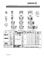
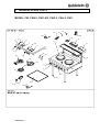
1
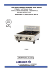
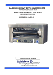
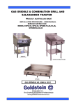
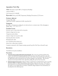
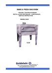
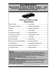
CHINESE COOKING RANGE
PROUDLY AUSTRALIAN MADE
INSTALLATION PROCEDURE – USER MANUAL
SERVICE INSTRUCTION
ALL MODELS
GAS APPROVAL NO. 2757
ESTABLISHED 1911
The Cooking Equipment Professionals
www.goldsteineswood .com.au
TABLE OF CONTENTS
1.
INTRODUCTION
Page 3
2.
INSTALLATION INSTRUCTIONS
Page 4 & 5
3.
COMMISSIONING
Page 6
4.
CLEANING/MAINTENANCE OF CHINESE WOK
Page 7
5.
CONVERSIONS INSTRUCTIONS
Page 8
6.
TECHNICAL DATA
Page 9
7.
PROBLEM SOLVING
Page 10
8.
DRAWINGS - SPARE PARTS
Page 11-12-13 & 14
9.
WARRANTY
Page 15
10.
BRANCHES
Page 16
IM003B2/p2
1. INTRODUCTION
Congratulations for purchasing your Goldstein commercial cooking appliance.
J. Goldstein & Co. is a wholly owned Australian company and has been
operating since 1911, building high quality products. The information in this
manual will assist your installer and ensure correct location and connection.
Thoroughly read the user instructions and the user maintenance sections, as
understanding your products, its operation, and its cleaning and service
requirements will provide you with long and satisfactory service. Failure to do
so could shorten the life of the product and decrease its efficiency. Please
ensure only authorised service technicians are called to any difficulties that may
arise.
INTRODUCTION
GOLDSTEIN CHINESE WOK GAS RANGE ALL MODELS
GOLDSTEIN WOKS are designed to give long and satisfactory service and
incorporate the best possible materials and workmanship. Proper installation,
adjustment and preventative maintenance are vitally important if efficiency and
appearance are to be maintained.
Read these instructions carefully as they contain important safety information
regarding the installation, use and maintenance of the appliance.
RECEIVING INSPECTION
• Check crates for handling damage. After carefully uncrating, check for “concealed”
damage. Report any damage immediately to carrier and to dealer.
• Remove check all loose items from unit and check contents as found on back of
warranty cards.
• Check type and capacity of gas supply.
• The type of gas for which this Wok Series is factory adjusted can be seen on the
rating plate, e.g. Approval No. Serial No, mj/M, Model, Test pressure point, kPa and
injector sizes located on the bottom front panel of the Wok.
“THE EQUIPMENT MUST BE INSTALLED BY A
LICENSED GASFITTER
NOTICE
PLEASE RETURN YOUR WARRANTY CARD
FAILURE TO DO SO WILL VOID WARRANTY
ON THE EQUIPMENT
IM003B2/p3
2. INSTALLATION INSTRUCTIONS
PRE-INSTALLATION OF THE WOK
• Check that there is sufficient clearance between doors and passageways to move
•
•
•
•
•
•
•
equipment into the cooking area.
Lift off wooden base.
Lay the Wok back on its back.
Place a piece of timber under the body of the Wok not on the Upstand to allow
clearance for your hand.
Attach the legs using bolts and washers provided and tighten them.
Then lift the Wok off its back being sure to lift on the body by placing hands under
space provided by timber.
Single hole Woks mount directly on the stand provided.
Peel off all protective film and remove any glue or oil with a suitable solvent.
INSTALLATION (FOR AUTHORISED GASFITTERS ONLY)
These installations MUST comply with the requirements of AS5601/AG601 local
authority gas, electricity and any other statutory regulations.
LPG connection MUST be supplied and connected with regulator as per standard
AS4563/AG300.
Note: AFTER ANY MAINTENANCE OR ADJUSTING OF GAS CONNECTED
COMPONENTS, A GAS LEAK TEST MUST BE CARRIED OUT, TO ENSURE
THERE ARE NO GAS LEAKING HAZARDS
• Adequate ventilation must be provided by a hood with vent and exhaust fan.
• Check the rating plate to ensure appliance is suitable for the gas supply to which
it will be connected and for information relative to gas input pressure and
consumption.
Please follow instructions carefully:
1. Set the unit in correct position (ENSURE THERE IS A MIN 25MM REAR WALL
CLEARANCE FROM COMBUSTIBLE MATERIALS AND THAT THE UNIT IS
PLACED ON A FIRE PROOF BASE) and adjust feet using a spirit levelling
side to side but tilting to the back to allow cooling water to drain back.
If more than one piece of equipment is in the line up, these adjustments will
have to be made relative to each other.
2 Have a licensed gas fitter or your local gas company connect the appliance to
the gas supply. The gas inlet connection can be seen on Page 9. The appliance
must be installed in accordance with rules of any authority having jurisdiction.
The regulator supplied must be installed on the gas inlet to the appliance. This
is supplied as a loose item and should be installed close to the appliance for
ease of servicing and to minimise pressure drop. Also an LPG regulator as per
standard AS4563/AG300 from (1.1.2005).
The pressure regulator (NG) and LPG standards (AS4563/AG300 1.1.05)
are supplied as a loose item and a hand stop tap must be supplied as
close to the appliance as possible to stop any pressure drop.
IM003B2/p4
2. INSTALLATION INSTRUCTIONS
3.
WATER CONNECTION (If applicable)
The Woks are fitted with two taps, one to control the flow of water from the filling
spout at the rear and one to control the table cooling jets. The appliance must
be connected to fresh water supply with pressure between 50 and 70 p.s.i. (3.5
to 5.0 bar).
Inlet water fitting is 12mm BSP.
4.
DRAIN CONNECTION (If applicable)
The Drain pipe should be cleaned at regular intervals. The drain must be
connected in conformity with requirements of local authority. The diameter of
the drain pipe must always be greater than the drain outlet from the appliance.
Drain connection is 51 mm BSP.
5.
On CW-1 Bench Model only has gas connection.
6.
All gas equipment MUST have an exhaust hood as per AS5601/AG601.
NOTE:
Models operating on LP GAS will be supplied with a regulator as from (1st January
2005) as new standard (AS4563/AG300).
IM003B2/p5
3. COMMISSIONING INSTRUCTIONS
COMMISSIONING (FOR AUTHORISED TECHNICIANS ONLY)
Note: All the appliances that leave our factory have been tested and adjusted
according to the specifications for the required gas. The regulator may have to
be adjusted to achieve the required gas pressure.
Note: Before igniting the wok ensure that all the protective plastic on unit has
been removed.
Each wok burner is fitted with an adjustable pilot (black knob) and separate controls for
the outer and inner wok burner (chrome knobs). The pilots should be ignited with a
hand sparking unit.
After installation of the appliance the installer should light all burners to ensure that
they are operating correctly. The burner flames should not have yellow tips nor should
they be too “hard”. Note the WOK burner has an adjustable bolt on the side of each
burner throat. This bolt can be screwed in/out to modify the flame type.
All appliances are tested and preset before leaving our factory, but small adjustments
may be necessary to suit local conditions.
Ensure that the pressure at the pressure test point on the manifold is as per the rating
plate.. If the two values are not the same, use a screwdriver to adjust the pressure
regulator (turning screw clockwise will increase the pressure).
Flame Failure Woks only
Turn the control knob to low and check that the flame size has decreased substantially.
If flame has not decreased, then using a small flat headed screwdriver adjust the ‘min
gas screw’ on the front of the gas control until the min flame gets to desired size
(turning screw clockwise will decrease the flame size).
If the appliance fails to operate correctly, check the following:
1.
2.
3.
4.
Data plate for correct gas type and pressure and adjust if necessary.
Correct aeration by adjusting the interrupter screws on the side of the burner
head. The flame should have a purple inner cone and a blue outer cone and
should not be noisy.
Injector size – check against data plate.
Check pilot flame size and adjust if necessary.
CAUTION WARNING
If flame or pilot goes out wait (5) minutes before relighting (reigniting).
IM003B2/p6
4. CLEANING/MAINTENANCE OF CHINESE WOK
DO NOT USE STEEL WOOL, ABRASIVE CLOTHS, CLEANSERS OR
POWDERS!
If it is necessary to scrape stainless steel to remove encrusted materials, soak
the area with hot cloths to loosen the material, and then use a wood or nylon
scraper.
DO NOT USE a metal knife, spatula, or any other metal tool to scrape stainless
Steel. Scratches are almost impossible to remove
CLEANING
For continued reliable operation of your Wok, regular cleaning is most essential.
Spillages of food products or liquids on the Wok will occur and these must not be
allowed to “burn on” (these spillages should be immediately cleaned up. If food
products or liquids spill over onto the burner, they can be totally immersed in hot soapy
water. After cleaning the Burners must be drained very thoroughly. If water is left in
the Burner, this will cause the gas flame to be weak and of poor colour, as well as
corroding the Burner.
For the cleaning of the stainless steel or vitreous enamel surfaces, use hot soapy water
and a soft cloth. Never use an abrasive cloth.
A CLEANER THAT IS COMPATIBLE WITH ALUMINIUM MUST BE USED ON
THE EQUIPMENT OTHERWISE THE GAS PIPING WITHIN THE UNIT WILL
BE DAMAGED AND THIS WILL AUTOMATICALLY VOID THE WARRANTY.
SERVICE
An authorised person or the local gas authority must handle any service problems that
arise. If Authorised Gasfitter cannot commission or adjust appliance they can contact
the state branch on Page 16. The operator should carry out only regular cleaning.
WARNING
NO FLAMMABLE MATERIALS OR FLUIDS SHOULD BE KEPT NEAR OR
ON APPLIANCE.
DO NOT SPRAY AEROSOLS IN THE VICINITY OF THIS APPLIANCE WHILE
IT IS IN OPERATION.
NOTE
WASH HOSES SHOULD NEVER BE USED ON THE APPLIANCE.
USE OF HOSES WILL VOID WARRANTY
IM003B2/p7
5. CONVERSION INSTRUCTIONS
To convert from N.G. to L.P. gas do the following:
1.
Replace N.G. burner injectors with L.P.G. injectors (refer to table on the this
page).
2.
Adjust needle valve to achieve desired pilot flame size.
3.
Disconnect regulator from gas supply line, disconnect natural gas regulator from
gas line reconnect LPG regulator on line..
4.
Reset pressure test point on manifold to 2.75 kPa.
5.
Adjust burner aeration bolt.
Relevant required gas pressure for use in conversion
Natural
L.P.
1.0 kPa W.G.
2.75 kPa W.G.
Town or manufactured gas 0.625 kPa W.G.
AN AUTHORISED GAS FITTER MUST CARRY OUT GAS CONVERSION.
INJECTOR SIZES
GAS TYPE BURNER
INJECTOR GAS RATING
(MM)
(MJ)
T.P.P.
(KPA)
INNER
OUTER
BOILING TOP
INNER
OUTER
BOILING TOP
INNER
OUTER
BOILING TOP
1.80
2.85
2.35
2.80
4.40
3.60
1.05
1.75
1.40
54
54
26
51
51
25
47
47
22
1.0
1.0
1.0
2.75
2.75
2.75
0.625
0.625
0.635
DUCKBILL & MONGOLIAN
N.G.
DUCKBILL
N.G.
MONGOLIAN
L.P.G.
DUCKBILL
L.P.G
MONGOLIAN
1.10
.95
.70
.60
81
81
82
89
1.0
1.0
2.75
2.75
STANDARD
N.G.
N.G.
N.G.
T.G.
T.G.
T.G.
L.P.
L.P.
L.P.
IM003B2/p8
6. TECHNICAL DATA
IM003B2/p9
7. PROBLEM SOLVING
TROUBLE SHOOTING
These troubleshooting procedures must be carried out only by a Goldstein Authorised
Maintenance & Repair Centre or Company specialising in restaurant cooking
appliances. The problems and possible solutions given below cover those most
commonly encountered.
FACTORY APPROVAL MUST BEOBTAINED PRIOR TO ANY WARRANTY WORK
BEING DONE OR GOLDSTEIN CANNOT BE HELD RESPONSIBLE.
1.
Low Flame on Burner
a)
Check gas supply pressure on TPP or Manifold – adjust if needed.
b)
Check air vent on regulator – Clean or replace.
c)
Look at ports on burner may be blocked – clean or drill out.
d)
Burner may be blocked inside – pull out and clean.
e)
Check injector size (Rating plate).
2.
Flame too high
a) Check gas pressure on TPP on Manifold – (behind S/S front). should be
1.0 kPa NG 2.75 kPa LPG.
b) Only part of burner works – Clean ports or injectors
c) Check size of injector on Rating Plate.
3.
Water not covering top of wok
a) Check level by spirit level. Should be level left to right with a small fall to
the back.
4.
Water leaking from Tap
a) Check washer in Tap. Replace if necessary???
b) Check handle on tap turns off.
5.
Water not draining from trough
a) Make sure drain not blocked at back of Wok. Clean
b) Check main drain.
6.
Pilot keeps going out (F.F.D. only)
a) Check Pilot may need to be cleaned or replaced.
b) Check thermocouple loose – Tighten
c) Replace thermocouple if necessary.
7.
Gas Tap hard to turn
a) Turn off gas pul tap apart – clean regrease – reassemble test for leaks
b) Replace if it cannot be fixed.
IM003B2/p10
8. DRAWING SPARE PARTS
MODEL: CW, CW2-2, CWC-2/R, CWC-2, CWL-2, CW3
12
15
13
7/30
10
15
3
16
6
2
9
24
5
17
6
OF
F
NO
NO
OF
F
1
19
4
OF
F
32
NO
NO
OF
F
11
32
1
18
28
25
27
NO
OF
F
26
F
NO
OF
1
OF
F
OF
F
NO
29
8
23
21
20
31
9
NO
4
22
IM003B2/p11
8. DRAWING - SPARE PARTS
MODEL: CW, CW2-2, CWC-2/R, CWC-2, CWL-2, CW3
ITEM No.
1.
2.
3.
4.
5.
6.
6.
6.
6.
7.
8.
9.
9.
10.
11.
12.
13.
13.
14.
14.
15.
16.
17.
18.
18.
18.
18.
18.
19.
19.
20.
21.
21
21.
22.
23.
24.
25.
26.
26.
27.
27.
28.
28.
29.
29.
30.
31.
32.
IM003B2/p12
CODE
MKNPLCW0
GCKCWP02
GPI000A4
MKNSSCK1
GCKCW000
GIJCW170
GIJCW105
GIJCW285
GIJCW180
GPI00002
MTAW0001
GRI0000A
GRI0000B
GTC00600
GBNCW000
GCKGR001
GIJCH170
GIJCH105
GIJCH285
GIJCH280
CW-00P18
CW-00P17
CW-00P16
CWL-2A02
CW---A07
CW-3-A07
CWC-2A07
CW-2-A07
MTACP600
MTACP750
GCU00010
CWC2-P10
.CW-3-P10
CW-2-P10
GTC00601
MLEPLBF1
GPI00004
GNZ00001
GNZCW007
GNZCW002
GBNCWJ04
GBNCWJ03
GNZCW005
GNZCW004
GBNCWDB5
GBNCWDB4
GPI00002
MKNPLCW1
CW-00P68
DESCRIPTION
KNOB – CW PILOT CONTROL OFF/OFF/OFF
GASCOCK – PILOT TOP (PT42)
PILOT ASSY (WOK RANGE)
KNOB – CHROME METAL CW/CHD GASCOCK GCKC
GASCOCK – CW – KB135B
INJECTOR – OUTER RING 1.70mm L/P (SP 1855)
INJECTOR – INSIDE RING 1.05mm L/P
INJECTOR – OUTER RING 2.85mm N/G (SP 1855)
INJECTOR – INSIDE RING 1.80mm N/G
2 WAY PILOT ASSY
WATER TAP ASSEMBLY – CONTROL COCK
RING – CW 13”
RING – CW 16”
THERMOCOUPLE – L=600mm
BURNER – CW (52.75MJ)
GASCOCK F/F PEL 21S
INJECTOR – OUTER RING 1.70mm L/P
INJECTOR – INNER RING 1.05mm L/P
INJECTOR – OUTER RING 2.85mm N/G
INJECTOR – INNER RING 2.80mm N/G
DRAIN COVER
STRAINER
WATER HOLDER
SHELF – STAINLESS STEEL CWL-2
SHELF – STAINLESS STEEL CW
SHELF – STAINLESS STEEL CW-3
SHELF – STAINLESS STEEL CWC-2, CWC-2/R
SHELF – STAINLESS STEEL CW-2
ARM – CP LAUNDRY 600mm TELESCO. HEAVY CW2
ARM – CP LAUNDRY 750mm TELESCO. HEAVY CW3
GAS COCK F/F FOR MONGOLIAN, DUCKBILL, BURNER
DRIP TRAY
DRIP TRAY – TRIPLE
DRIP TRAY – DOUBLE (WITH FLAME FAILURE)
THERMOCOUPLE 600mm WITH 11/32” THREAD
FEET – PLASTIC BULLET 2D
PILOT HEAD – S/S, CW RING BURNER
NOZZLES – WASH DOWN SPRAY HEAD, NUT & WASHER
DUCKBILL NOZZLE 1.10mm N/G
DUCKBILL NOZZLE .70mm L/P
MONGOLIAN BURNER L/P
MONGOLIAN BURNER N/G
L/P NOZZLE L/P MONGOLIAN
N/G NOZZLE N/G MONGOLIAN
DUCKBILL BURNER N/G
DUCKBILL BURNER L/P
2 WAY PILOT ASSY
KNOB – GASCOCK (GCV00010)
PILOT COVER FOR FLAME FAILURE
8. DRAWING - SPARE PARTS
MODEL: CW-2B2, CW-3B2, CW-5B2
34
33
32
35
22
15
3
30
2
16
31
5
24
17
6
OF
9
F
NO
NO
OF
F
1
7
4
19
6
OF
F
NO
NO
OF
F
11
38
1
OF
F
18
OF
F
NO
NO
38
28
25
27
NO
OFF
NO
OFF
26
NO
OFF
OFF
NO
29
10
OFF
NO
8
NO
OFF
36
12
13
35
21
23
14
20
39
37
IM003B2/p13
40
8. DRAWING - SPARE PARTS
MODEL: CW-2B2, CW-3B2, CW-5B2
ITEM No.
1.
2.
3.
4.
5.
6.
6.
7.
8.
9.
10.
11.
12.
13.
14.
15.
16.
17.
18.
18.
19.
19.
20.
21.
21
22.
23.
24.
25.
26.
26.
27.
27.
28.
28.
29.
29.
30.
30.
31.
31
32.
32.
33.
33.
34.
35.
36.
37.
38.
39.
40.
CODE
MKNPLCW0
GCKCWP02
GPI000A4
MKNSSCK1
GCKCW000
GIJCW140
GIJCW235
GPI000A6
MTAW0001
GRI0000A
GTR00002
GBNCW000
GBNBTL00
GBNBTS00
GBNSP000
CW-00P18
CW-00P17
CW-00P16
CWB22A07
CWB32A07
MTACP600
MTACP750
CW-00P26
CW-3-P10
CW-2-P10
GPI00002
MLEPLBF1
GPI00004
GNZ00001
GNZCW002
GNZCW007
GBNCWJ03
GBNCWJ04
GNZCW005
GNZCW004
GBNCWDB4
GBNCWDB5
GIJCW105
GIJCW180
GIJCW285
GIJCW175
GIJCH170
GIJCH105
GIJCH285
GIJCH280
GCKGR001
GTC00600
GTC00450
MKNPLCW1
CW-00P68
GCU00010
GTC00601
IM003B2/p14
DESCRIPTION
KNOB – CW PILOT CONTROL OFF/OFF/OFF
GASCOCK – PILOT TOP (PT42)
PILOT ASSY. (WOK RANGE)
KNOB – CHROME METAL CW / CHD GASCOCK GCKC
GASCOCK – CW KB135B
INJECTOR – BOILING TOP 1.4mm L/P
INJECTOR – BOILING TOP 2.35mm N/G
PILOT ASSEMBLY FOR SIDE BURNERS
WATER TAP ASSEMBLY – CONTROL COCK
RING – CW 13”
TRIVET – 12” PF RANGE
BURNER – CW (52.75MJ)
BURNER – CW SIDE (LONG) PF
BURNER – CW SIDE (SHORT) PF
BURNER SUPPORT (GBNBTL00 / GBNBTS00)
DRAIN COVER
STRAINER
WATER HOLDER
SHELF – STAINLESS STEEL (CW2-B2)
SHELF – STAINLESS STEEL (CW-3B2)
ARM – CP LAUNDRY 600mm TELESCO. HEAVY
ARM – CP LAUNDRY 750mm TELESCO. HEAVY
DRIP TRAY – 12” SINGLE
DRIP TRAY – TRIPLE
DRIP TRAY – DOUBLE (WITH FLAME FAILURE)
2 WAY PILOT ASSEMBLY
FEET – PLASTIC BULLET 2D
PILOT HEAD – S/S, CW RING BURNER
NOZZLES – WASH DOWN SPRAY HEAD, NUT & WASHER
DUCKBILL NOZZLE .70mm L/P
DUCKBILL NOZZLE 1.10mm N/G
MONGOLIAN BURNER L/P
MONGOLIAN BURNER N/G
L/P NOZZLE L/P MONGOLIAN
N/G NOZZLE N/G MONGOLIAN
DUCKBILL BURNER L/P
DUCKBILL BURNER N/G
INJECTOR – WOK INNER RING 1.05mm L/P
INJECTOR – WOK INNER RING 1.80mm N/G
INJECTOR – OUTER RING 2.85mm N/G (SP 1855)
INJECTOR – OUTER RING 1.75mm L/P (SP 1855)
INJECTOR – OUTER RING 1.70mm L/P
INJECTOR – INNER RING 1.05mm L/P
INJECTOR – OUTER RING 2.85mm N/G
INJECTOR – INNER RING 2.80mm N/G
GASCOCK F/F PEL 21S
THERMOCOUPLE – L=600mm
THERMOCOUPLE – L=450mm
GASCOCK KNOB
PILOT COVER
GASCOCK F/F FOR MONGOLIAN, DUCKBILL BURNER
THERMOCOUPLE – L=600 WITH 11/32” THREAD
9. WARRANTY
Installation must be carried out according to local regulations by qualified trade
persons.
Isolating switch(es), shut-off valves etc must be within easy reach of the machine
for future service and maintenance requirements.
If in doubt call GOLDSTEIN/ESWOOD or their representative for further
information. No responsibility will be accepted for defects or damages by
improper installation, for changes to the product not authorised by
GOLDSTEIN/ESWOOD or for operation outside the technical specifications.
GOLDSTEIN/ESWOOD warrants their products to be free from defects in
material and workmanship under “normal use and service”. This does not include
normal wear and tear of parts. GOLDSTEIN/ESWOOD will repair or replace any
parts, which in GOLDSTEIN/ESWOOD’s sole judgement are defective in material
or workmanship, in accordance with the warranty offered.
This undertaking covers the provision of labour and parts for 12 months from the
date of delivery to the purchaser. This undertaking applies only to state capitals.
Remote areas are not covered by this commitment and special enquiries should
be made. (Note: Travel time not covered by warranty).
“To the maximum extent permitted by law, any liability on Goldstein/Eswood’s
part or on the part of its servants or agents for loss or damage of any kind
whatsoever in connection with the products, including liability for or in respect of
any claim arising out of contract, negligence or statute, shall not, in any event,
exceed $100”
Labour under warranty is supplied free of charge during normal working hours,
Monday to Friday. Should warranty work be requested outside of our normal
working hours a labour charge will be applied equivalent to a normal hour rate,
without out of hours penalty rates. (Refer to last page of this manual for your
closest branch for warranty repair services).
IM003B2/p15
10. J GOLDSTEIN & CO PTY LTD BRANCHES
For inquiries please call your nearest state branch:
Head Office
211-213 Woodpark Road
New South Wales 2564
Phone:
02 9604 7333
Fax:
02 9604 5420
Victoria
Unit 13
260-264 Wickham Road
Moorabbin
Victoria 3189
Phone:
03 9553 1488
Fax:
03 9553 0785
Queensland
Unit 3
49 Logan Road
Woolloongabba
Queensland 4102
Phone:
07 3891 1466
Fax:
07 3393 1333
South Australia
Suite 26
283-287 Sir Donald Bradman Drive
Brooklyn Park
South Australia 5032
Phone:
08 8238 3423
Fax:
08 8238 3400
Western Australia
10 Wittenberg Drive
Canning Vale
Western Australia 6155
Phone:
08 9456 0559
Fax:
08 9456 0554
IM003B2/p16