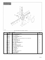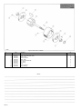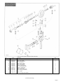
1
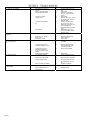
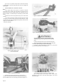
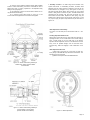
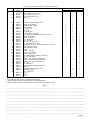
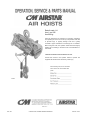
Rated Loads: 1/4
thru 1 ton/ 225
thru 900 kg.
Follow all instructions and warnings for inspecting, maintaining
and operating this hoist. The use of any hoist presents some risk
of personal injury or property damage. That risk is greatly
increased if proper instructions and warnings are not followed.
Before using this hoist, each operator should become thoroughly
familiar with all warnings, instructions and recommendations in
this manual.
Retain this manual for future reference and use.
Forward this manual to the operator. Failure to operate this
equipment as directed in this manual may cause injury.
Before installing hoist, fill in the information
below. Refer to the Hoist and Motor data
plates.
PRINTED IN U.S.A.
MAY, 1996
COPYRIGHT 1996, COLUMBUS McKINNON CORPORATION
PART NO. 117209-1
This book contains important information to help you install, operate and
maintain your new CM AIRSTAR Air Hoist. We recommend that you study its
contents thoroughly before putting your hoist to use. Through proper
installation, application of correct operating procedures, and by practicing the
recommended maintenance suggestions you will be assured maximum
service from your hoist.
fied factory-trained service men and stock approved CM replacement parts.
Replacement parts information is also included in this book for your
convenience. Since it will likely be a long time before parts information is
needed, we suggest that, after you have become familiar with operation and
preventive maintenance procedures, this book be carefully filed for future
reference.
Complete inspection, maintenance and overhaul service is available for CM
AIRSTAR Air Hoists at recognized CM Repair Stations. Refer to your
telephone directory yellow pages under "HOISTS." They are staffed by quali
EQUIPMENT ILLUSTRATED AND DESCRIBED HEREIN IS NOT
DESIGNED OR SUITABLE FOR LIFTING OR LOWERING PERSONS.
INDEX
)ECTION I
GENERAL DESCRIPTION
PAGE
Paragraph 1-1 General ....................................................................................................................................................................................... 3
Paragraph 1-2 Basic Construction . . . . . . . . . . . . . . . . . . . . . . . . . . . . . . . . . . . . . . . . . . . . . . . . . .3
Paragraph 1-3 Differences Between Models and Sizes . . . . . . . . . . . . . . . . . . . . . . . . . . . . . . . . . . . . .3
Paragraph 1-4 Hoist Data . . . . . . . . . . . . . . . . . . . . . . : . . . . . . . . . . . . . . . . . . . . . . . . . . . . . . . .3
SECTION II INSTALLATION
Paragraph 2-1 General ............................................................................................................................................................................................... 4
Paragraph 2-2 Suspending Hoist . . . . . . . . . . . . . . . . . . . . . . . . . . . . . . . . . . . . . . .,. . . . . . . . . . . .4
Paragraph 2-3 Connecting Hoist to Air Service . . . . . . . . . . . . . . . . . . . . . . . . . . . . . . . . . . . . . . . . .4
Paragraph 2-4 Hoisting and Lowering Speed Adjustments . . . . . . . . . . . . . . . . . . . . . . . . . . . . . . . . . .5
SECTION III OPERATION
Paragraph 3-1 General ............................................................................................................................................................................................... 5
Paragraph 3-2 Pre-Operational Checks . . . . . . . . . . . . . . . . . . . . . . . . . . . . . . . . . . . . . . . . . . . . . . .5
Paragraph 3-3 Operating Hoist . . . . : . . . . . . . . . . . . . . . . . . . . . . . . . . . . . . . . . . . . . . . . . . . . . . .5
Paragraph 3-4 Pulling and Pivoting Hoist and Load . . . . . . . . . . . . . . . . . . . . . . . . . . . . . . . . . . . . . .6
Paragraph 3-5 Upper and Lower Limit Stops . . . . . . . . . . . . . . . . . . . . . . . . . . . . . . . . . . . . . . . . . .6
Paragraph 3-6 Operating Precautions . . . . . . . . . . . . . . . . . . . . . . . . . . . . . . . . . . . . . . . . . . . . . . .6
)ECTION IV LUBRICATION
Paragraph 4-1 General ............................................................................................................................................................................................... 7
Paragraph 4-2 Service Air Line Lubricator . . . . . . . . . . . . . . . . . . . . . . . . . . . . . . . . . . . . . . . . . . . .7
Paragraph 4-3 Gearcase . . . . . . . . . . . . . . . . . . . . . . . . . . . . . . . . . . . . . . . . . . . . . . . . . . . . . . . .7
Paragraph 4-4 Lubricate Load Chain . . . . . . . . . . . . . . . . . . . . . . . . . . . . . . . . . . . . . . . . . . . . . . . .7
Paragraph 4-5 Lubricate Upper Hook and Lower Block Assembly . . . . . . . . . . . . . . . . . . . . . . . . . . . .7
Paragraph 4-6 Lubricate Control Shaft, Brake Cam and Valve Shifter . . . . . . . . . . . . . . . . . . . . . . . . . .7
Paragraph 4-7 Lubricate Trolley Wheel Bearings . . . . . . . . . . . . . . . . . . . . . . . . . . . . . . . . . . . . . . . .7
SECTION V MAINTENANCE
Paragraph 5-1 General ............................................................................................................................................................................................... 7
Paragraph 5-2 Thirty-Day Inspection . . . . . . . . . . . . . . . . . . . . . . . . .'. . . . . . . . . . . . . . . . . . . . . .7
Paragraph 5-3 Annual Inspection ....................................................................................................................................................................... 9
SECTION VI TROUBLE SHOOTING . . . . . . . . . . . . . . . . . . . . . . . . . . . . . . . . . . . . . . . . . . : . . . . . . 10
SECTION VII DISASSEMBLY AND REASSEMBLY
Paragraph 7-1 General .............................................................................................................................................................................................. 11
Paragraph 7-2 Disassembly . . . . . . . . . . . . . . . . . . . . . . . . . . . . . . . . . . . . . . . . . . . . . . . . . . . . . 11
Paragraph 7-3 Cleaning and Inspection . . . . . . . . . . . . . . . . . . . . . . . . . . . . . . . . . . . . . . . . . . . . . 14
Paragraph 7-4 Reassembly . . . . . . . . . . . . . . . . . . . . . . . . . . . . . . . . . . . . . . . . . . . . . . . . . . . . .14
Paragraph 7-5 Testing Hoist . . . . . . . . . . . . . . . . . . . . . . . . . . . . . . . . . . . . . . . . . . . . . . . . . . . . 16
Paragraph 7-6 Pendant Throttle Control Assembly . . . . . . . . . . . . . . . . . . . . . . . . . . . . . . . . . . . . . 17
SECTION VIII PARTS LIST
Paragraph 8-1 Introduction ........................................................................................................................................................................................ 17
Paragraph 8-2 Parts List . . . . . . . . . . . . . . . . . . . . . . . . . . . . . . . . . . . . . . . . . . . . . . . . . . . . . . . 17
Figure 8-1 Frame and External Parts (Coil Chain) . . . . . . . . . . . . . . . . . . . . . . . . . . . . . . . . . . . . 18
Figure 8-2 Frame and External Parts (Roller Chain) . . . . . . . . . . . . . . . . . . . . . . . . . . . . . . . . . . 20
Figure 8-3 Gearing, Sprocket and Load Brake Parts . . . . . . . . . . . . . . . . . . . . . . . . . . . . . . . . . . 22
Figure 8-4 Control Head Parts . . . . . . . . . . . . . . . . . . . . . . . . . . . . . . . . . . . . . . . . . . . . . . . .23
Figure 8-5 Air Motor Parts . . . . . . . . . . . . . . . . . . . . . . . . . . . . . . . . . . . . . . . . . . . . . . . . . . . 24
Figure 8-6 Control Cylinder and Pendant Throttle Parts . . . . . . . . . . . . . . . . . . . . . . . . . . . . . . . 25
Figure 8-7 Special Parts Table - Spark Resistant Models . . . . . . . . . . . . . . . . . . . . . . . . . . . . . . . 26
NOTICE: Information contained in this book is subject to change without notice.
Page 2
1-1. GENERAL. CM AIRSTAR Air Hoists are precision built chain type
hoists which are built in three rated loads, 1/4, 1/2, and 1 ton. Each size is
available in pull cord control and pendantthrottle control models. In addition,
there are model variations with coil type or roller type load chains and hook or
lug type suspensions. Coil chain hoists are also provided in spark resistant
models. (Note: Spark resistant models have rated loads of 3/8 and 3/4 ton.)
1-2. BASIC CONSTRUCTION. All sizes and models are of the same basic
design, having many common and interchangeable parts. They consist
primarily of an aluminum alloy frame which houses a vane type air motor,
chain sprocket wheel, and gearing. A shoe-type brake is mounted on one end
of frame and is encased in an aluminum alloy end cover. A control head
assembly with built-in muffler and air inlet swivel connection is mounted on
opposite end of frame. An upper suspension hook or lug bracket is attached
to the top of the frame. Either a special nickel steel roller type load chain or an
alloy steel coil type load chain with spring-latch type lower block assembly is
employed to raise and lower loads. A block and chain operated limit stop
lever is mounted at bottom of frame and is pinned to throttle valve control
shaft. Hoist operation is controlled by either pull cords or a pendant throttle
control assembly.
reeved (two parts of chain). Standard lift is 10' though increased lifts may be
ordered.
a. Control differences are in methods employed for operating hoist. There are
two types, pull cord control and pendant throttle control. These are further
described in Section I I I, paragraphs 3-1 and 3-3.
b. Two types of load chains are used as the lifting medium, roller chain and
coil chain. The roller type chain is a special precision manufactured nickel
steel chain. The coil type chain is full-flexing, electric welded, link chain;
carburized alloy steel on standard models and surface hardened
chrome-nickel stainless steel on spark resistant models. Both types are
especially designed for use in hoisting.
c. Suspension differences include a conventional hook type mounting and a
lug type mounting. Hook suspension allows portability, permitting hoist to be
easily moved from job to job. Lug suspension allows rigid trolley mounting of
hoist on an overhead I-beam to permit traversing hoist and load. Rigid
mounting of trolley on hoist affords maximum headroom advantage, saving up
to 3-3/16" compared to a hoist hook-suspended on a trolley.
1-4. HOIST DATA.
1-3. DIFFERENCES BETWEEN MODELS AND SIZES. The main differences
between hoist models are in the type of control, type load chain and type
suspension employed. These are described in paragraphs (a.) through (c.)
below. Differences between sizes are in reeving of the load chain. On 1/4 and
1/2 ton hoists, the load chain is single reeved (one part of chain); on 1 ton
hoists, the chain is double
12018C.
12019C
*Rated Loads: 1/4, 1/2 and 1 ton Air Pressure (recommended): 90 psi Air
Consumption: 48 cfm at 90 psi Net Weight (basic hoist): 36 pounds
Suspension: Hook or lug Control: Pull Cord or Pendant Throttle
*For standard models. Spark resistant models are rated at 3/8 and 3/4 ton.
12020C
Figure 1-1. Views of Various Air Hoist Models.
Page 3
2-1. GENERAL. CM AIRSTAR Air Hoists are completely lubricated and load
tested before being shipped from the factory. To place hoist in service, attach
to a suitable overhead suspension (Paragraph 2-2) in area to be used;
connect hoist to nearest air supply (paragraph 2-3); and check and adjust
hoist speed (paragraph 2-4).
b. If hoist is suspended by trolley, provide sufficient hose to reach from air
source to farthest point of trolley travel. CM Hose Trolleys are recommended
to keep hose up out of the way (see Figure 2-2).
2-2. SUSPENDING HOIST.
a. On hook suspended hoists, select a suitable overhead support in area
hoist is to be used (one capable of holding combined weight of hoist and its
rated load) and hang hoist up. Be certain that upper hook is firmly seated
in center of hook saddle and that the spring safety latch is properly
closed over hook opening. In some cases, it may be necessary to first
remove spring latch before hook will fit over a support. Reinstall latch after
hook is engaged.
b. On lug suspended hoists, select a suitable overhead support in area hoist
is to be used (one capable of holding combined weight of hoist and its rated
load). Mount hoist using through bolts of appropriate size to fit mounting holes
in suspension lug at top of hoist. Use only suspension bolts provided by CM.
(See table below.)
The structure used to suspend hoist must be of sufficient strength
to withstand reasonable forces
to which hoist and support may be subjected. Hoist must be
aligned with load to avoid side pulls.
Figure 2-2. Air Hoist Supported by CM Hose Trolleys.
c. On rigid mount trolley suspended hoists, the trolley side plates must be
properly spaced so trolley will fit (beam on which hoist will operate.
Adjustment for various I-beam sizes is accomplished by rearrangement of
spacer washers on through bolts which connect trolley side plates to hoist
suspension lug. Refer to instruction sheet furnished with CM Rigid Mount
Trolleys for complete instructions.
c. A filter and lubricator unit (Figure 2-3) must be installed between air
source and air hose leading to hoist. These keep air flowing to hoist free of
dirt and add lubricant to air so internal parts of motor are constantly
lubricated. Use Air Hoist Motor Oil or good grade 10W machine oil
(approximately viscosity 150 SSU at 100°F.). Multi-viscosity, detergent type
engine oil is not recommended. Feed one drop of oil for every 50 to 75 cubic
feet of air going through the air motor.
If trolley is mounted on an open-end beam, end stops must
be installed to prevent trolley from running off the end of the
beam resulting in injury to operator and others, and
damages to load and other property.
d. If chain container is to be used on hoist, install it following instructions
furnished with container.
2-3. CONNECTING HOIST TO AIR SERVICE.
a. Connect hoist to nearest filtered and lubricated air source using.minimum
1/2" I.D. air hose assembly (see Figure 2-1). Avoid use of reducing bushing
and nipple or hose assemblies of smaller diameters which may cause
restrictions.
Page 4
Figure 2-3. Air Filter and Lubricator Unit.
d. The recommended operating air pressure for all capacities of CM
AIRSTAR Air Hoists is 90 psi. When line pressure exceeds 100 psi (while
hoist is operating), it is recommended that a pressure regulator valve be
provided in the air supply line to maintain proper pressure. However, there is
a wide range of pressures within which the hoists will operate. Refer to
"Performance Charts." See Figure 2-5.
2-4. HOISTING
AND
LOWERING
SPEED
ADJUSTMENTS.
a. Hoist speed is adjusted at the factory to give maximum lifting speed and is
set at average between minimum and maximum lowering speed.
b. To adjust the hoisting or lowering speed, turn appropriate regulator screw
(Figure 2-4) in either direction a little at a time while operating hoist under
load.
3-1. GENERAL. Operation of CM AIRSTAR Air Hoists is controlled by either
pull cords or a pendant throttle control, depending upon the model. Pull Cord
Control models have pull type control cords (Figure 3-1) suspended from a
rocker type lever at bottom of hoist that actuates the throttle control valve.
Pendant Throttle Control models have a convenient lever type control valve
handle (Figure 3-2) suspended from the control cylinders on sides of control
head housing.
Do not lift more than rated load except for test purposes.
Overloading hoist can result in chain breakage, hook
deformation and other failures which can cause serious
injury and damage. A test at greater than rated load should
be a properly supervised official test only, not an operator
test. If any load sustaining parts have been altered, replaced
or repaired, hoist should be load tested at 125% of rated load
by a designated, qualified person, with a written report
recording test load, as recommended in ANSI B30.16 Safety
Standards.
Figure 2-4. Hoisting and Lowering Speed Adjustment.
Maximum lowering speed with rated load is very
high. Adjust with care. Heads of adjusting screws
should not extend beyond outer surface of housing.
c. When the screwdriver slots on ends of adjusting screws are horizontal
(hoist in normal suspended position), the hoist speeds will be at either
minimum speed or maximum speed. Rotating the screws 180° in either
direction will give a full adjustment between minimum and maximum speed
limits. NOTE: Screws have arrow stamped on end to assist operator with
adjustment.
3-2. PRE-OPERATIONAL CHECKS. Check the following before operating
hoist with load:
a. Inspect chain anchor connections at side of hoist frame and at upper hook
or lug mounting bracket on 3/4 and 1 ton double reeved models. Anchor
screw or pin should be secure and not bent or broken. Chain should be solidly
anchored.
b. Check hoist brake for proper adjustment and operation. Refer to Section V,
paragraph 5-2, d.
c. Check hooks. They should not be bent or distorted and should not be
opened beyond the correct opening sizes given in Figure 5-3. Hook latches
should not be bent or damaged and springs not broken.
d. Check chain to make sure it is not twisted or kinked. Be sure lower block
(3/4 and 1 ton, double reeved models) has not been capsized.
Never operate hoist with defective chain anchor pins, brake
or hooks.
e. Lubricate chain per paragraph 4-4.
3-3. OPERATING HOIST. With hoist installed and air pressure turned on,
hoist is operated in the following manner:
a. Pull Cord Control.
(1) Pull top handle (marked with arrow pointing up) down to raise load.
(2) Pull bottom handle (marked with arrow pointing down) down to lower
load.
(3) Release handle being used to stop either lifting or lowering.
(4) Speed of lifting and lowering is varied between slowest (inching) to
full speed by the pull exerted on control handle being used.
NOTE: Hoist Speeds are shown in feet per minute (f.p.m.1.
Figure 2-5. Hoist Performance Charts.
Page 5
Figure 3-1. Pull Cord Control Handles.
b. Pendant Throttle Control.
(1) Depress throttle valve lever marked
"UP" to raise load. See Figure 3-2.
(2) Depress throttle valve lever marked
"DOWN" to lower load.
(3) Release lever being depressed to
stop either lifting or lowering.
(4) Speed of lifting and lowering is varied
by the position of the throttle valve lever being
depressed.
Figure 3-2. Pendant Throttle Control Handle.
3-4. PULLING AND PIVOTING HOIST AND LOAD.
a. On Pendant Throttle Control models, the valve handle is supported
by a strain cable that is suitable for pulling trolley suspended hoists
when empty or lightly loaded. Use a tag line or pole to pull or push
loads to traverse heavily loaded hoists. Observe caution to stay clear of
loads.
b. To pivot load, push on one corner of load. Lower hook will swivel
through 360° to permit load to be swung to the desired position. The
upper hook (hook suspension models) is also designed to rotate so that
side pulls will swing hoist to face the load, thus reducing side thrust.
Equipment covered herein is not designed or suitable as a
power source for lifting or lowering persons.
Safe operation of an overhead hoist is the operator's responsibility.
Listed below are some basic rules that can make an operator aware of
dangerous practices to avoid and precautions to take for his own safety
and the safety of others. Observance of these rules in addition to
frequent examinations and periodic inspection of the equipment may
save injury to personnel and damage to equipment.
a. Operate hoist cautiously to become familiar with its performance.
3-5. UPPER AND LOWER LIMIT STOPS. A lower block and chain
operated limit stop is provided to guard against overtravel of load in
either raising or lowering direction, which can cause damage to hoist.
When highest position is reached, the lower block trips the control lever
(Figure 3-3). When lowest position is reached, the tail end of load chain
trips the control lever (Figure 3-4). The control lever is connected to the
control shaft which actuates inlet valves controlling air pressure to air
motor. Limit stops are intended as safety devices and should not be
used as a routine basis to stop travel of lower block or shut off hoist.
Page 6
b. Do not load hoist beyond rated load.
c. Take up chain slack carefully to avoid jerking load.
d. Never use hoist load chain as a sling.
e. Always be sure there is no twist in coil load chain. On 3/4 and 1 ton
hoists, check to see that lower block is not capsized between strands of
chain.
f. Check both upper and lower limit stop operation by raising or lowering
empty hook to limit of travel. Hoist must shut off.
g. When lifting load, make certain it is free to move and will clear all
obstructions.
h. Stand clear of all loads and never lift or travel loads over people.
j. Avoid operating hoist when hook is not centered under hoist. Be sure
that hoist trolley or other support mechanism is correctly positioned for
handling the load before lifting.
k.
Guide load so as to have it under control at all times.
I.
Do not operate hoist with twisted, kinked or damaged
chain.
m. Do not operate damaged or malfunctioning hoist.
n. Conduct periodic visual inspection for signs of damage or wear.
o. Observe inspection and maintenance procedures described in this
manual.
p. Never lift or transport a load until all personnel are clear. Never lift
people on hook or load.
q. Do not divert attention from load while operating hoist. Never leave a
suspended load unattended.
r.
Do not use limit stop as normal operating stop. This
is a safety device only.
s.
Do not "jog" unnecessarily.
t. Personnel not physically fit or properly qualified, shall not operate
hoist.
u.
Do not remove or obscure warning labels.
v. Use common sense and best judgement whenever operating a hoist.
Observe American National Standard Safety Standard, ANSI B30.16,
latest issue.
a. Coil Chain. Under ordinary conditions, only weekly attention will be
necessary for alloy steel chain. Under hot and dirty conditions, it may be
necessary to clean chain at least once a day and lubricate it several times
between cleanings. Thoroughly clean chain with an oil solvent and relubricate
by coating it lightly with penetrating oil and graphite. Make sure that lubricant
coats wear surfaces between links.
Stainless steel load chain must be well lubricated at all times and must be
inspected daily when in use.
b. Roller Chain. Under ordinary conditions, only monthly attention will be
necessary. Under hot and dirty conditions, weekly attention may be required.
Thoroughly clean chain with an oil solvent and apply a good grade of S.A.E.
20 motor oil. Wipe off excess oil. When subjected to excessive moisture or
corrosive atmospheres, DO (dripless oil) lubricant from American Grease
Stick Company is recommended for use on roller chain in place of regular
motor oil.
4-5. LUBRICATE UPPER HOOK AND LOWER BLOCK ASSEMBLY.
a. On 3/4 and 1 ton hoists, apply a few drops of S.A.E. 60 oil on shank of
upper hook where it enters suspension bracket.
b. On single line hoists (1/4, 3/8 and 1/2 ton) disassemble upper and lower
hooks as described in 7-2.b.(4) and grease thrust bearings with a good grade
of bearing grease.
c. On double line hoists (3/4 and 1 ton) lower blocks, disassemble as
described in 7-2.b.(5) and grease needle bearings for sprocket shaft and hook
with a good grade of bearing grease.
4-6. LUBRICATE CONTROL SHAFT, BRAKE CAM AND VALVE SHIFTER.
a. Apply a few drops of S.A.E. 60 oil on control shaft at bearing points.
b. Apply graphite grease on valve shifter and on brake cam.
4-7. LUBRICATE TROLLEY WHEEL BEARINGS. If hoist is mounted on a
trolley, apply light grease to wheel bearings as recommended by trolley
literature.
4-1. GENERAL. The lubrication services outlined in paragraphs 4-2 through
4-7 should be performed at regular intervals to maintain top hoist
performance and insure long life. Frequency of lubrications will depend on
type of hoisting service hoist is subjected to and should coincide with
preventive maintenance inspections. See Section V Maintenance.
4-2. SERVICE AIR LINE LUBRICATOR. Servicing air line filter and lubricator
unit is of primary importance since it is the only source of lubrication for
control valves and air motor. Fill lubricator with Air Hoist Motor Oil or good
grade 10W machine oil (approximate viscosity 150 SSU at 100°F.). Multi
-viscosity, detergent type engine oil is not recommended.
4-3. GEARCASE. The gearcase is grease packed at the factory and requires
no further greasing unless the gearcase is for any reason disassembled.
Then, at reassembly, the parts should be washed clean (using commercial
fluid) and repacked with NLGI EP-2 Grease.
4-4. LUBRICATE LOAD CHAIN. A small amount of lubricant will greatly
increase load chain life; therefore, chain should not be allowed to run dry.
Chain should be cleaned and lubricated as directed in paragraphs a. and
b. below, depending upon type of chain. User should set up a regular
schedule for chain lubrication after observing operating conditions for a few
days. Use Bar and chain Oil (LUBRIPLATE or equal) on load chain.
Before performing any internal work on hoist, remove load
and be certain air is shut off.
5-1. GENERAL. Preventive maintenance services required on CM AIRSTAR
Air Hoists are for the most part simple periodic inspection procedures to
determine condition of hoist components. Below are suggested inspection
procedures, based on daily average hoist usage.
Hoist subjected to severe service or to adverse environments should
be examined weekly or as conditions warrant.
5-2. THIRTY-DAY INSPECTION. Hoist may be left suspended.
a. Inspect Load Chain.
(1) Operate hoist under load and observe operation of chain over
sprocket in both directions of chain travel. Chain should feed smoothly into
and away from the sprocket. If chain binds, jumps or is noisy, first see that
Page 7
it is clean and properly lubricated. If trouble persists, inspect chain and
mating parts for wear, distortion or other damage.
(2) Coil Type Load Chain. Clean chain for inspection. Examine
visually for gouges, nicks, weld splatter, corrosion or distorted links.
Slacken chain and check bearing surfaces between links for wear,
Figure 5-1. Greatest wear will often occur at sprocket at high or low
point of lift, particularly when hoist is subjected to repetitive lifting
cycles. Case hardness of chain is about .015" deep. Chain must be
replaced before the case is worn through. Also check chain for
elongation using a vernier caliper (Figure 5-2). Select an unworn,
unstretched section of chain (usually at slack or tail end) and measure
and record the length over the number of chain links (pitches) indicated
in Figure 5-2. Measure and record the same length of a worn section in
the load side of the chain. Obtain the amount of wear by subtracting the
measurement of the unworn section from the measurement of the worn
section. If the result (amount of wear) is greater than the amount
specified in the "ALLOWABLE CHAIN WEAR" table, the chain has
elongated beyond the maximum allowable length and must be replaced.
Chain with excessively pitted, corroded, nicked, gouged, twisted or
worn links should be replaced using only factory approved chain. Never
weld or attempt to repair coil chain.
Load chain for spark resistant models is made of stainless steel.
Surface hardness treatment is no more than .001" deep and the core is
lower in hardness than standard alloy steel load chain. For these
reasons the rated capacity of spark resistant models is lower than that
of standard models as follows:
Do not assume that load chain is safe because it measures
below replacement points given herein. Other factors, such
as those mentioned in visual checks above, may render
chain unsafe or ready for replacement long before
elongation replacement is necessary.
When replacing coil load chain, use only factory
approved chain conforming to factory specifications for
material, hardness, strength and link dimensions. Chain
not conforming to CM hoist specifications may be
dangerous as it will not fit in the load sprocket and chain
guide correctly, causing damage to hoist, and it will
wear prematurely, deform and eventually break.
(3) Roller Type Load Chain. Visually check for possible twists,
broken links, wear or elongation. Check roller chains for elongation from
wear by pulling chain taut and measuring as follows: On RC-625 or H-5
size chain (5/8" pitch), measure distance over a length of 20 pitches
(center-to-center distance between 21 rivets) - it must not exceed
12-3/4 inches. If chain exceeds this limit, replace damaged section or
install new load chain assembly. Check chain for twist. If twist in any 5'
extension exceeds 15°, replace chain. Check chain for camber. If any
section has side bow exceeding 1/4" in five feet, replace chain. Use
only factory approved chain. If chain is to be spliced to replace
damaged section, it is recommended that this be done by a recognized
CM Repair Station, since splicing link must have a spun head requiring
special tools. Spring link must not be used except to secure the tail
chain to the hoist frame. (See Figure 7-1.)
Figure 5-1. Check Chain Wear at Bearing
Surfaces Between Links.
It must not be assumed that load chain is safe because it
measures below replacement points given herein. Other
factors, such as those mentioned in visual checks above,
may render chain unsafe or ready for replacement long
before elongation replacement is necessary.
(4) Check anchor end of chain at side of hoist frame for damage
to last link, also connecting link on roller chain hoists. Replace
damaged parts.
(5) Check connection of chain to lower block on 1/4, 3/8 and 1/2
ton hoists. Replace parts showing evidence of damage, twisting or
elongation.
(6) Check connection of chain to anchor on side of suspension
bracket on double reeved, 3/4 and 1 ton hoists. Replace parts showing
evidence of damage, twisting or elongation.
(7) Lubricate load chain if required. See paragraph 4-4, Section
IV.
Figure 5-2. Checking Coil Chain Using
Vernier Caliper.
Page 8
b.
Inspect Lower Block.
(1) Check for bent or distorted hook. If hook is opened beyond the
dimension given in Figure 5-3, it must be replaced. Also check to see
that hook swivels, and is free to pivot on roller chain models. Lubricate
these points if necessary.
(2) On 3/4 and 1 ton hoists, check sprocket and bearings in lower
block for freedom of movement and signs of damage. Lubricate if
necessary. Replace damaged parts.
down before the motor starts to actuate, the brake is out of adjustment.
(2) To adjust brake, insert hex key through hole in brake cover.
Turn screw counterclockwise to tighten brake or clockwise to loosen
brake (see Figure 7-15).
5-3. ANNUAL INSPECTION. Hoist must be disconnected from air
service and removed from overhead suspension. Hoists subjected to
severe service or to adverse environments should be examined
weekly or as conditions warrant.
a. Hoist should be partially disassembled as necessary to inspect hoist
parts noted in paragraphs b. through h. below. Refer to Section VII for
disassembly and reassembly steps as noted.
b. Inspect Brake. Remove brake housing cover and brake shoes as
outlined in paragraph 7-2.c. Check brake shoe linings and brake wheel
for wear and scoring. Replace badly worn or scored parts. Check
condition of brake cam and spring. Replace any damaged parts.
c. Inspect Internal Load Gears. Remove gear plate and intermediate
gears as outlined in paragraph 7-2.f. Check condition of gear teeth on
internal gear, intermediate gears, and motor shaft pinion. Replace worn
or damaged parts.
d. Inspect Chain Sprocket and Bearings. Remove sprocket and
internal gear as a unit, paragraph 7-2.f. Check condition of teeth or
pockets on chain sprocket and inspect ball bearing assemblies.
Replace worn or damaged parts.
(3) Check hook latches. Replace damaged or bent latches or
broken springs.
Hooks, upper or lower, damaged from chemicals,
deformation or cracks or having more than 15 percent in
excess of normal throat opening or more than 10
degrees twist from the plane of the unbent hook, or
opened, allowing the hook latch to bypass hook tip must
be replaced.
Any hook that is twisted or has excessive throat
opening indicates abuse or overloading of the hoist.
Other load bearing components of the hoist should be
inspected for damage. (See Section V, paragraph 5-3
below.)
e. Inspect Throttle Valve Shifter. Remove valve shifter and control
shaft (paragraph 7-2.c.) and shifter pin (paragraph 7-2.d.). Check
condition of shifter, pin and shaft bearings. Replace worn or damaged
parts.
f. Inspect Throttle Valve Housing. Remove throttle housing assembly
(paragraph 7-2.d.) and disassemble it as outlined. Check condition of
throttle valve, valve bushing (in housing) and "0" rings on valves.
Replace worn or damaged parts.
g. Inspect Air Motor. Remove air motor assembly from hoist
(paragraph 7-2.e.). Check motor for condition of bearings, possible rotor
rubbing on body or end plates, blade freedom in rotor slots, shaft and
gear. If motor appears to be in good condition, do not service other than
lubricating well with light oil.
h. Reassemble and Test Hoist. Reassemble hoist as outlined in
Section VII, paragraph 7-4. After reassembly, test hoist in accordance
with paragraph 7-5.
c.
Inspect Upper Suspension.
(1) On hook suspended models, check for bent or distorted hook.
If hook is opened beyond the dimension given in Figure 5-3, it must be
replaced. Also check to see that hook swivels. Lubricate if necessary.
(2) On push trolley suspended models, check condition of trolley
parts and lug bracket. Replace bracket or any trolley parts which are
damaged or cracked.
(3) Check hook latch. Replace damaged or bent latch or broken
spring.
d.
Check Brake Operation.
(1). With air turned on and with rated load attached to lower hook,
operate hoist to raise load, applying pressure to pull cord handle or
throttle control lever. If load drifts
Page 9
Trouble
6-1. Hoist does not operate.
6-2. Hoist will not hold load in
suspension.
6-3. Control lever does not return to horizontal position.
6-4. Hoist loses power.
6-5. Cannot regulate speed by
control handles.
Page 10
2.
3.
Probable Cause
Insufficient air pressure at
source.
Brake improperly adjusted.
Clogged air intake screen.
2.
3.
4.
5.
Excessive overload.
Clogged valve.
4.
5.
6.
Valve shifter not functioning.
6.
7.
Motor failure.
7.
1.
Brake out of adjustment.
1.
2.
Brake lining oily, glazed or
badly worn.
Excessive overload.
Control shaft bent.
2.
1.
3.
1.
1.
3.
1.
Remedy
Check air pressure and adjust.
Adjust brake.
Shut off air - disconnect
air hose - clean inlet swivel
screen.
Reduce load.
Remove valve caps - remove
any obstructions, clean and
lubricate valve.
Check for proper installation of drive pin in valve
shifter and control lever and
also that shifter pin is
assembled solidly to throttle
valve.
Disassemble motor and
check rotor blades. Replace
defective parts.
Adjust brake.
Remove brake arms and
replace with new.
Reduce load.
Remove shaft and straighten
or replace.
2.
Foreign material, rust or
corrosion causing it to bind.
2.
3.
3.
4.
1.
Foreign material, rust or
corrosion in control cylinders or pendant throttle
control.
Brake improperly adjusted.
Insufficient air pressure.
2.
Clogged air intake screen.
2.
3.
Clogged muffler screen.
3.
4.
1.
Worn or broken rotor blades.
Brake improperly adjusted.
4.
1.
Adjust brake.
Check air pressure and adjust.
See this Section, paragraph
1.
Remove throttle valve housing. Clean screen and muffler.
Replace rotor blades.
Adjust brake.
2.
Speed adjustment screws
improperly set.
2.
Readjust screws.
4.
1.
Remove shaft and clean.
Lubricate bearings, brake
cam and valve shifter.
Clean control cylinders.
Trouble
6-6. Cannot regulate speed by
pendant handle.
1.
2.
6-7. Hoist lifting or lowering
speed differs from rated
speed at full load.
1.
2.
3.
4.
Probable Cause
Brake improperly adjusted.
Control cylinders improperly adjusted.
Valve shifter or control
shaft bent or damaged.
Incorrect air pressure or
inadequate air supply.
Speed adjustment screws
improperly set.
Loss of power.
1.
2.
1.
2.
3.
4.
Remedy
Adjust brake.
Adjust control cylinder set
screws.
Repair or install new parts,
and lubricate.
Check pressure near hoist
when hoist is operating.
Readjust screws. See Figure
2-4.
See paragraph 6-4.
link to tail end anchor on coil chain models. If hoist is connected to air service,
run chain out of hoist by operating control in "lowering" direction. If hoist is not
connected to air service, the chain can be pulled out of hoist by hand while
holding brake open by pulling down on control lever.
7-1. GENERAL.
a. The following disassembly and reassembly instructions apply to all models
of CM AIRSTAR Air Hoists. Where needed, variations to instructions are
provided to cover differences between models (suspensions, controls, load
chain, capacity sizes) with applicable models specifically noted.
b. A complete teardown procedure is given. However, if only certain parts
require repair or replacement, a partial teardown may be performed, using
applicable portions of the instructions.
c. For easier handling during disassembly, the following disassembly steps
may, where conditions permit, be completed before hoist is removed from its
overhead suspension or disconnected from its air supply: Remove chain
container, if hoist is so equipped. Remove lower block and load chain
assembly, following procedure outlined in paragraph 7-2.b.
d. These hoists contain precision machined parts and should be handled with
care at disassembly and reassembly. When removing or installing parts with
press fits, be careful to apply pressure evenly. On ball bearings, apply
pressure to face of inner or outer race, whichever is adjacent to mating part.
This will avoid damage to bearing races from brinelling by pressing through
bearing balls. Apply a thin film of oil to parts having a tight fit when installed.
Figure 7-1. Removing Connecting Link at Tail End
of Load Chain (Roller Chain Models).
7-2. DISASSEMBLY.
a.
Removal of Hoist from Overhead Suspension.
(1) Turn off air at source.
(2) Operate control to bleed air from hoist.
(3) Disconnect air hose at inlet swivel.
(4) Remove hoist from overhead suspension,
b.
Removal of Lower Block and Load Chain Assembly.
(1) On models with single reeved load chains (1/4, 3/8 and 1/2 ton),
disconnect end of load chain from tail end anchor boss at side of hoist frame.
Remove chain anchor, by prying off spring clip and remove connecting link,
attaching chain to anchor boss on roller chain models (Figure 7-1). Remove
socket head cap screw, holding end
(2) On models with double reeved chains (3/4 and 1 ton), disconnect
end of chain as in paragraph (1) above, run chain out of hoist by operating it
in "lowering" direction, and disconnect opposite end of chain from anchor at
side of upper suspension bracket.
(3) On single reeved 1/4, 3/8 and 1/2 ton models, separate load chain
(coil or roller type) from lower block assembly. Drive out small spring pin
securing lower block pin in lower block and push out lower block pin to
release chain. On roller chain models, an adapter is used to attach chain to
lower block. This adapter is removed from end of chain by first driving out
small spring pin and then pushing out adapter pin.
(4) Lower blocks (1/4, 3/8 and 1/2 ton) are of a pinned construction,
permitting individual replacement of body, thrust bearing, or hook. To
disassemble, drive spring pin from hook nut. With pin removed, hold hook nut
from turning with drift punch and rotate hook to unscrew it from nut. Separate
hook, bearing shield, needle bearing and two thrust washers from body.
Hook and nut are drilled at assembly and are replaced only as an assembly.
Page 11
(5) On 3/4 and 1 ton (double reeved) models, the lower block assembly
is disassembled by removing socket head screws and nuts holding body
halves together.
c.
Removal of Brake Cover, Control Lever and Load
Brake.
(1) On pendant throttle control models, for convenience, disconnect
control hoses from air cylinders, open strain cable "S" hook at eye bolt on
throttle housing and remove pendant throttle control assembly from hoist.
Refer to paragraph 7-6 for disassembly and reassembly of pendant throttle
control.
(2) Remove two screws securing brake housing cover to frame and lift
off cover.
(3) To remove control lever and shaft, drive spring pins from control
lever (Figure 7-2) and valve shifter at end of shaft using a drift punch. Lightly
tap valve shifter end of shaft and withdraw shaft by pulling on brake cam end
(Figure 7-3). As shaft is withd°, ~i - . . :~
control lever will fall free.
Figure 7-4. Special Tool for Removing Brake Spring.
Figure 7-5. Removing Brake Spring Using Special Tool.
Do not pry spring all the way off with screwdriver, since
spring is apt to fly in most any direction with considerable
force.
(5) Remove brake shoes. Be sure not to lose steel fulcrum balls.
(6) Remove steel balls from recesses in sides of upper brake boss.
d. Removal and Disassembly of Control Head Assembly.
(1) Remove control head assembly by taking out six socket head
screws and lifting assembly from frame (Figure 7-6).
Figure 7-2. Driving Spring Pin from
Control Lever and Shaft.
Figure 7-6. Removing Control Head Assembly.
Figure 7-3. Removing Control Shaft.
(4) Remove brake spring by carefully prying it up evenly with a
screwdriver until spring is about half-way off. Using brake spring spreader
(Part No. 306989, Figure 7-4), remove spring from brake arms (Figure 7-5).
Page 12
(2) Lift muffler and screen from recess in control head housing.
(3) On pendant throttle control models, remove control cylinder
assemblies from each side of control head housing (Figure 7-14). On pull
cord control models,
remove throttle valve spring retainer caps from each side of housing (Figure
7-13). Valve springs, spring guides and "O" ring seals can now be removed
from valve bore at each side of housing.
(4) The throttle valve is retained in the control head by the valve shifter
pin. The pin is assembled with LOCTITE on the threads and should not be
removed for routine servicing. If valve is to be removed, use a hex key to
remove pin from bottom of throttle valve. (See Figure 7-13.) The valve can
now be removed from bushing in housing. The throttle valve bushing is
pressed into place and honed to provide a .0001 to .0003 inch clearance with
valve. If bushing is scored, worn, or otherwise damaged, the housing and
bushing assembly should be replaced along with the valve.
(5) Remove air inlet swivel body and bushing from top of housing.
Retain bushing gasket for reuse. Pull strainer screen from housing bore.
(6) Remove retaining ring from bottom of swivel body and pull off
bushing. Remove "O" ring seal from its groove in bushing.
(7) Disassemble control cylinder (pendant throttle control models) by
removing cylinder lock ring. Cylinder and cap will come off with lock ring. Lift
out spring and then remove piston and seal assembly from cylinder. Piston
shaft "O" ring seal and retainer washer will drop out as piston is removed.
(5) Inspect blades for wear or breakage. Inspect end plate, rotor and
body for damage. Since the end plates and body are matched and doweled at
assembly, they are not serviced separately. If there is significant damage,
replace motor.
f.
Removal of Brake Wheel, Internal Load Gears and
Sprocket.
(1) Rotate brake wheel until holes in web are aligned with four socket
head cap screws (Figure 7-8). Remove screws, then lift brake wheel off
(Figure 7-9) after prying up lightly and evenly with screwdriver to free ball
bearing. Ball bearing and clamp plate are pressed off after removing retaining
ring from wheel hub.
Figur;: r-'o. Removing ~ag uciLvv~;jacuring
Bearing Clamp Plate.
e. Removal and Disassembly of Air Motor.
(1) Remove air motor from hoist frame by placing entire unit on motor
end and lifting frame straight up as shown. DO NOT tap on end of motor shaft
since this will destroy critical rotor alignment and damage motor. If necessary,
motor may be grasped at bearing boss on the dead end plate to assist in
removal.
Figure 7-J. Removing Brake Wheel and
Ball Bearing Assembly.
(2) Remove four socket head screws securing gear plate to frame and
lift off plate and intermediate gears as a unit (Figure 7-10). Do not remove the
two socket head screws from flange around brake wheel bearing hole (Figure
7-9) unless it is necessary to replace intermediate gears.
Figure 7-7. Removing Motor from Frame.
(2) Motor is a unit construction and generally should not be
disassembled. However, if it is felt that the blades need replacing, the dead
(opposite drive end) end plate can be removed to inspect the blades.
(3) Removal of dead end plate requires a puller to remove the end plate
bearing from the shaft.
(4) Remove (3) button head cap screws from dead end plate. Attach
puller to end plate with two 1/4-28 screws taking care not to turn them into
end plate more than 1/4 inch, thus hitting and damaging rotor. Remove end
plate by turning puller screw against motor shaft.
Figure 7-10. Removing Gear Plate and
Intermediate Gears.
Page 13
(3) On roller chain models, remove two fillister head screws attaching
chain stripper to frame and lift out stripper. Chain stripper on coil chain
models is integral with chain guide.
(4) On coil chain models, remove four fillister head screws attaching
chain guide and stripper assembly to hoist frame. This will free guide to allow
sprocket to be pulled through it as it is removed in step (5). Refer to Figure
7-11.
(5) Rotate internal gear (Figure 7-10) until holes in web align with six
socket head screws securing bearing clamp plate to frame. Remove internal
gear, chain sprocket and ball bearings as a unit (Figures 7-11 and 7-12). It
may be necessary to tap sprocket to free ball bearings from bores in frame.
7-3. CLEANING AND INSPECTION. Before reassembly, all parts should be
thoroughly cleaned and inspected to determine their serviceability. Replace
all parts that are excessively worn or damaged. Minor nicks and scratches
should be filed to remove raised edges.
NOTE: Bearings that are sealed are lubricated at the factory for
normal life of the bearing and must not be washed. If they are
exposed to wash or infiltration with foreign matter, they must be
replaced.
7-4. REASSEMBLY.
a. General. The procedure to be followed to reassemble hoist is in reverse
order of the disassembly steps outlined in paragraph 7-2. Listed below are
special assembly precautions which should be observed to assure proper
assembly.
b. Assembly of Motor. When reassembling motor, observe the following
precautions:
(1) If any blade replacement is required, the full set of blades should be
replaced. Blades must be installed so that the edges with chamfered corners
face down into the slots.
(2) Reassemble end plate and bearing as follows. Remove dowel pins
locating end plate to body. Support shaft and press bearing onto shaft, using
a drift that contacts both inner and outer race of bearing. Use a feeler gage
between end plate and body to make sure the bearing is not pressed onto
shaft so far as to bow the end plate. Align dowel pin holes in end plate with
those in body and assemble pins. Assemble three button head cap screws.
(3) Rotor blade replacement is the only field service recommended on
air motors. See paragraph 7-2.e. For any other repairs the air motor should
be returned for factory servicing.
(4) Lubricate motor with small amount of Air Hoist Motor Oil or good
grade 10W machine oil (approximate viscosity 150 SSU at 100°F.).
Multi-viscosity, detergent type engine oil is not recommended.
Figure 7-11. Removing Internal Gear, Chain Sprocket
and Ball Bearing Assembly (Roller Chain Model).
(6) To disassemble intermediate gear, sprocket and ball bearing
assembly, remove retaining ring and pull outer ball bearing from sprocket.
Remove spindle nut from other end of sprocket and pull internal gear free of
sprocket shaft. Remove clamp plate and pull off remaining ball bearing.
c. Assembly of Control Head. At reassembly of control head and throttle
valve, observe these precautions:
(1) Lightly oil throttle valve and bushing with S.A.E. 20 oil. If shifter pin
was removed from valve, assemble valve with threaded hole facing slot at
bottom of bushing in housing (Figure 7-13). Shifter pin should be assembled
with LOCTITE, Extreme care must be taken not to get any LOCTITE on
valve outside diameter since this will lock up valve and scrap the complete
head assembly.
NOTE: Apply lubricating oil to "0" rings and "U" seals before installing
and take care during installation so as not to cut, pinch, or otherwise
damage them.
(2) Use new "0" ring seals at each end of valve. Install spring guides
and valve springs in bores on each side of housing and secure with spring
retainer (pull cord models) or control cylinders (pendant throttle control
models). Use new "0" ring gaskets.
(3) At reassembly of control cylinders (pendant throttle control models),
use new "U" type seals on piston heads and "0" ring seals on piston stems.
Be sure "U" type seals face direction illustrated in Figure 7-14.
Figure 7-12. Removing Internal Gear, Chain Sprocket
and Ball Bearing Assembly (Coil Chain Model).
Page 14
(4) Use new "0" ring gaskets on adjusting screws. When installing
screws in control head housing, turn them in until heads are flush or
slightly below face of housing. Adjustment is accomplished during
testing of hoist, paragraph 2-4.
(5) At reassembly of screen and air inlet swivel, install a new "0"
ring seal inside swivel bushing.
(6) In mounting control head housing on hoist, use a new
motor-to-head air seal gasket and a new head-to-frame gasket.
d. Assembly of Brake. If the brake linings show excessive wear,
replace brake shoes. In reassembling the brake, the brake wheel
assembly goes into position first and is fastened in place by the four
screws referred to in paragraph 7-2.f.0). (See Figures 7-8 and 7-9.)
Now place the steel fulcrum balls in their receiving cup, using a small
amount of thick grease to hold them in place. The balls should retract
completely into the receiving cups. Now place the shoes up to the
fulcrum balls and brake wheel. Replace the brake spring, using the
spreader tool to start the spring over the shoes. (See Figures 7-4 and
7-5.) Tap the spring into place. Adjust brake shoes per instructions in
Figure 7-15.
Brake Adjustment at Reassembly:
Turn screw "A" in until arms pivot on fulcrum ball to make "C" = .010
- .015".
Checking Adjustment Without Load:
Without load, and with air turned off, open brake arms manually, by
operating limit lever, to see if brake wheel can be turned freely by
hand. If wheel refuses to turn, the brake may not be properly
adjusted. Recheck adjustment, and then if the wheel does not turn
freely, check for possible damage, such as bent brake arms,
improper lining, brake cam slippage or other malfunctions in the
unit.
Brake Adjustment With Load:
(1) With load on hook, pull "UP" control cord (or press "UP"
lever), slowly! Load must not creep down before motor starts. Turn
adjusting screw out as required.
(2) Brake must stop and hold load in both directions.
Figure 7-13. Section View Showing Assembly of
Throttle Valve, Springs and Valve Shifter
in Control Head.
Figure 7-14. Section View Showing Assembly of
Control Cylinder on Control Head
(Pendant Throttle Control Models).
Figure 7-15. Brake Adjustments.
Page 15
e.
Installation of Load Chain.
(1) To install roller type load chain, first temporarily install
connecting link on tail end of load chain. Then, with the air off, brake
cover removed, and brake shoes locked in "open" position (with wedge
between control lever and hoist body), turn brake wheel in "hoist"
direction and feed chain in through lever control into chain sprocket.
Once chain is over sprocket, brake cover can be replaced, hoist
connected to air, and the chain run through hoist under power until
sufficient chain has been run through to allow tail end to be attached to
boss on side of frame with chain anchor. On single reeved hoist, attach
lower block to load end of chain. On double reeved hoist, run lower
block assembly onto chain and attach load end of chain to lug
suspension bracket.
(2) When installing coil chain on the hoist, make sure the weld on
the second link faces "out" or away from the sprocket. (See Figures
7-16 and 7-17). Now, with the air off, brake cover removed, and brake
shoes locked in "open" position (with wedge between control lever and
hoist body), turn brake wheel in "hoist" direction and feed chain in
through lever control into chain sprocket. Continue to feed the chain
through until approximately 15" to 16" hangs through the tail chain side
of the hoist. Take the first link and swing it up (do not twist) (see Figure
7-16) to the frame boss and fasten in place. The rest of the chain cab
be pulled through, and then the lower block fastened in place (on single
reeved hoist). On double reeved hoist, allow approximately 17" to 18" of
chain to hang on the lifting direction side (Figure 7-17). Run the lower
block assembly onto chain and swing (do not twist) the remainder of the
chain up and attach to lug on suspension bracket. Remove wedge from
between lever and frame and replace covers.
Figure 7-17.
Installing Double Reeved Load Chain
(3/4 and 1 Ton Models).
f. Assembly of Control Cords. On pull cord models, control cords
must be attached to control lever as follows: Facing air inlet end of
hoist, the cord to top handle (arrow pointing up) should be attached to
right end of lever; cord to bottom handle (arrow pointing down) attached
to left end of lever.
g. Assembly of Pendant Throttle Control. On pendant throttle control
models, control hoses must be attached to cylinders on throttle valve
housing as follows: Facing air inlet end of hoist, the hose to "DOWN"
lever side of pendant handle should be connected to cylinder on righthand side of housing; hose to "UP" lever side should be connected to
cylinder on left-hand side of housing. The third hose connects to tapped
hole in bottom left side of control head and at top rear of handle.
NOTE: Chain must not be twisted and link welds must be
positioned as shown in Figure 7-17.
7-5. TESTING HOIST.
a. General. After completion of assembly and before placing hoist in
service, hoist should be tested to insure proper operation. To test:
Suspend hoist from an overhead supporting member of sufficient
strength to carry combined weight of hoist and rated load; connect to air
supply of correct pressure; and perform the following checks and
adjustments:
b. Check Control Operation. Pull down on pull cord handle or depress
lever on pendant control briefly to determine that hook travels in the
direction to correspond with control being operated. If load hook travels
in a direction opposite to control being operated, the pull cords or
control hoses are improperly installed. With Pendant Control Hoists the
control lever should attain a full throw when each lever on the handle is
fully depressed. If full movement of control lever is not accomplished,
the set screw in the corresponding control cylinder should be turned in.
If full movement occurs before lever is fully depressed, the set screw
should be turned out. The screw should not extend beyond end of
cylinder.
c. Check Hoist Under Rated Load. Attach rated load to lower hook
and check hoist operation.
(1) Operate hoist to raise load. When control is released, hoist
should stop and hold load at that level.
FIGURE 7-16. Installing Single Reeved Load Chain
(1/4, 3/8 and 1/2 Ton Models).
Page 16
(2) Operate hoist to lower load a short distance, then release control.
Hoist should stop and hold load at that level.
(3) Operate hoist to lower load and observe rate of speed at which load
descends. Adjust lowering and hoisting speeds to the desired rate of speed
as outlined in paragraph 2-4.
c.
Reassembly.
(1) Clean all parts in cleaning solvent and carefully inspect for wear or
damage before reassembly.
(2) Install new air seal gaskets on bushing seats in the handle housing.
(3) Install new "0" ring gaskets on valve bushings. Insert springs and
valves in bushings and install new "0" ring seals on ends of valves. Valves
and bushings can now be reinstalled in handle housing using spanner tool.
"0" rings should be lubricated before reassembly.
(4) Position control levers on housing, align holes and install lever pin.
(5) Place guard over levers and secure to housing with four machine
screws.
(6) Reinstall control handle assembly on hoist. Attach control hoses to
handle housing as outlined in paragraph 7-4.g.
Do not lift more than rated load except for test purposes.
Overloading hoist can result in chain breakage, hook
deformation and other failures which can cause serious
injury and damage. A test at greater than rated load should
be a properly supervised official test only, not an operator
test. If any load sustaining parts have been altered, replaced
or repaired, hoist should be load tested at 125% of rated load
by a designated, qualified person, with a written report
recording test load, as recommended in ANSI B30.16 Safety
Standards.
7-6. PENDANT THROTTLE CONTROL ASSEMBLY.
a. General. After long periods of use, the pendant throttle control assembly
will require some maintenance attention. To service the control handle
assembly, shut off air supply, bleed air from hoist and control, and disconnect
hoses and strain cable at control handle. Disassemble and reassemble
control handle as outlined in paragraphs b. and c. below.
b. Disassembly.
(1) Remove four screws and lift control lever guard from handle.
(2) Drive lever pin from handle housing and separate two control levers
from housing.
(3) Using a suitable spanner tool, unscrew bushings and valves from
handle housing. Remove air seal gaskets from bushing seats in the handle
assembly. Remove "0" ring seals from ends of valves and pull valves and
valve springs from bushings. Remove "0" ring gaskets from bushings.
8-1. INTRODUCTION. Parts illustrations and parts lists covering CM
AIRSTAR Air Hoists bearing model number given on front cover will be
found on following pages. When ordering replacement parts, include with
order the exact Catalog Number and Model Number from hoist nameplate.
8-2. PARTS LIST. The parts lists consist of four columns. The first column,
Ref. No., is the index number of the parts on the exploded view illustrations.
The second column, Part Number, lists the number of the part for ordering
purposes. The third column names and gives a brief description to help
identify the part. The last column(s) list the total number of times the item is
used in the assembly of which it is a part.
NOTICE
Information herein is subject to change without notice. Parts must be
order from a recognized CM Repair Station or from a CM Hoist
Distributor.
NOTES
Page 17
Figure 8-1 . Frame and External Parts - Coil Chain Models.
Ref.
No.
1
2
3
t4
t5
t6
7
8
9
10
11
12
13
14
15
18
19
22
23
t24
t25
Part
Number
BAH-105
BAH-108
BAH-107
BAH-106
BAH-145
BAH-146
BAH-147
BAH-148
BAH-149
BAH-150
BAH-151
BAH-152
BAH-170
BAH-171
BAH-172
BAH-113
BAH-153
BAH-119
BAH-115
BAH-116
BAH-1 17
Description
Bolt - Suspension Bracket
Lockwasher - Shakeproof, External
Nut - Hex, Cadmium Plated
Hook and Bracket Assembly - Suspension
Hook and Nut Assembly - Upper (Includes Ref. No. 6)
Latch Kit
Bushing - Machinery
Bracket - Suspension
Washer - Thrust, Bearing
Bearing Assembly - Needle
Shield - Bearing
Nut - Hook
Pin - Spring Drive
Screw - Hex Socket Head Cap
Washer - Flat
Cover - Brake Housing
Screw - Slotted Head
Shaft - Control
Bushing - Oilite, Control Shaft
**Chain - Load, Coil Type (11'-5" Lg.)
"Chain - Load, Coil Type (22'-7" Lg.)
Lever - Control
(Continued On Next Page)
Page 18
1/4 Ton
2
2
2
1
1
1
1
1
2
1
1
1
1
1
1
1
2
1
3
1
1
Quantity Required
1/2 Ton
2
2
2
1
1
1
1
1
2
1
1
1
1
1
1
1
2
1
3
1
1
1 Ton
2
2
2
1
1
1
2
1
3
1
1
Figure 8-1. Frame and External Parts - Coil Chain Models (Cont'd.).
Ref.
No.
t26
t27
t28
Part
Number
BAH-154
BAH-155
BAH-156
BAH-157
BAH-158
Description
Quantity Required
1/4 Ton
1/2 Ton
1 Ton
1
1
1
1
1
1
Block Assembly - Lower (1/4 Ton)
Block Assembly - Lower (1/2 Ton)
Body - Lower Block (1/4 Ton)
Body - Lower Block (1/2 Ton)
Latch Kit
I
t29
30
31
32
33
34
35
t36
37
38
39
40
41
t
t42
43
t44
t45
t46
t47
t48
49
50
51
52
53
54
t55
t56
57
58
t59
BAH-160
BAH-149
BAH-150
BAH-151
BAH-152
BAH-121
BAH-122
BAH-124
BAH-125
BAH-126
BAH-128
BAH-127
BAH-129
BAH-161
BAH-130
BAH-132
BAH-135
BAH-136
BAH-137
BAH-131
BAH-146
BAH-133
BAH-134
BAH-141
BAH-142
BAH-143
BAH-138
BAH-139
BAH-140
BAH-146
BAH-101
BAH-162
BAH-173
BAH-174
BAH-175
Hook and Nut Assembly (With Latch)
Washer -Thrust, Bearing
Bearing Assembly - Needle
Shield - Bearing
Pin - Spring Drive
Nut - Hook
Pin - Spring Drive
Pin - Connecting, Lower Block
Cord Assembly - Control (Includes Ref. Nos. 37 thru 40)
Handle - Down Control
Handle - Up Control
Cord - Down Control
Cord - Up Control
Clip - Cord, 1/4" (Not Shown)
Pin - Spring Drive, Control Lever
Block Assembly-Lower (1 Ton, Includes Ref. Nos. 42 thru 49)
Body - Lower Block (Pair)
Bearing Assembly - Needle
Washer
Sprocket - Coil Chain
Screw - Socket Head Cap
Latch Kit - Lower Hook
Hook, Bearing and Nut Assembly (With Latch)
Nut - Hex, Self-Locking
Bracket - Lug Suspension (Parallel Mount)
Bracket - Lug Suspension (Parallel Mount)
Bracket - Lug Suspension (Cross Mount)
Pin - Cotter
Pin - Chain Anchor
Hpok and Bracket Assembly (With Latch)
Latch Kit
Frame Assembly (Includes Ref. No. 23)
Lockwasher - Spring
Label - Rated Load
1/4 Ton
1/2 Ton
1 Ton
I
1
2
1
1
1
1
1
1
1
1
1
1
1
1
1
1
1
2
1
2
1
1
1
1
1
1
1
1
1
1
1
1
1
1
1
2
1
1
1
1
1
1
1
1
1
2
2
1
3
1
1
3
1
1
2
1
1
1
1
2
1
-
1
-
1
tSee Special Parts Table (Figure 8-7) for Spark Resistant Models.
*Hook nut is drilled in place on hook shank and is not available separately.
**Load chain lengths listed are for standard 10 foot lifts. Longer chains are available on order.
NOTES
Page 19
Figure 8-2. Frame and External Parts - Roller Chain Models.
Ref.
No.
1
2
3
4
5
6
7
8
9
10
11
12
13
14
15
16
19
20
21
22
Part
Number
BAH-105
BAH-108
BAH-107
BAH-106
BAH-145
BAH-146
BAH-147
BAH-148
BAH-149
BAH-150
BAH-151
BAH-152
BAH-201
BAH-172
BAH-113
BAH-153
BAH-119
BAH-203
BAH-204
BAH-1 17
Description
Bolt - Suspension Bracket
Lockwasher - Shakeproof, External
Nut - Hex, Cadmium Plated
Hook and Bracket Assembly - Suspension
Hook and Nut Assembly - Upper (Includes Ref. No. 6)
Latch Kit
Bushing - Machinery
Bracket - Suspension
Washer - Thrust, Bearing
Bearing Assembly - Needle
Shield - Bearing
Nut- Hook
Pin - Spring Drive
Link Assembly - Roller Chain (For Connecting Tail End of
Chain Only. Must Not Be Used to Join Chain.)
Cover - Brake Housing
Screw - Slotted Head
Shaft - Control
Bushing - Oilite, Control Shaft
"Chain - Load, Roller Type (11'-1/2" Lg.)
"Chain - Load, Roller Type (22'-1" Lg.)
Lever - Control
(Continued On Next Page)
Page 20
1/4 Ton
2
2
2
1
1
1
1
1
2
1
1
1
1
1
1
2
1
3
1
1
Quantity Required
1/2 Ton
2
2
2
1
1
1
1
1
2
1
1
1
1
1
1
2
1
3
1
1
1 Ton
2
2
2
1
1
1
1
1
1
1
1
1
2
1
3
1
1
Figure 8-2. Frame and External Parts - Roller Chain Models (Cont'd.).
Ref.
No.
23
Part
Number
BAH-215
BAH-216
BAH-217
24
25
26
27
28
29
30
31
32
33
34
35
36
37
38
39
40
41
42
43
44
45
46
48
49
50
51
52
53
54
55
56
57
58
59
60
BAH-154
BAH-155
BAH-156
BAH-157
*
BAH-152
BAH-151
BAH-149
BAH-150
BAH-160
BAH-158
BAH-121
BAH-122
BAH-218
BAH-219
BAH-124
BAH-125
BAH-126
BAH-128
BAH-127
BAH-129
BAH-161
BAH-207
BAH-220
BAH-135
BAH-136
BAH-211
BAH-131
BAH-146
BAH-133
BAH-134
BAH-138
BAH-213
BAH-212
BAH-146
BAH-101
BAH-162
BAH-222
BAH-171
BAH-170
BAH-173
BAH-174
BAH-175
Description
Adapter - Roller Load Chain
Block Assembly - Lower, Complete (Includes Ref. Nos.
23, 24, 33, 34, 35 & 36)
Block Assembly - Lower, Complete (Includes Ref. Nos.
23, 24, 33, 34, 35 & 36)
Block Assembly,- Lower (Includes Ref. Nos. 25 thru 32)
Block Assembly - Lower (Includes Ref. Nos. 25 thru 32)
Body - Lower Block (1/4 Ton)
Body - Lower Block (1/2 Ton)
Nut - Hook
Pin - Spring Drive
Shield - Bearing
Washer - Thrust, Bearing
Bearing Assembly - Needle
Hook and Nut Assembly (With Latch)
Latch Kit
Pin - Spring Drive
Pin - Connecting, Lower Block
Pin - Spring Drive
Pin - Connecting, Roller Chain Adapter
Cord Assembly - Control (Includes Ref. Nos. 37 thru 40)
Handle - Down Control
Handle - Up Control
Cord - Down Control
Cord - Up Control
Clip - Cord, 1 /4" (Not Shown)
Pin -Spring Drive, Control Lever
Block Assembly-Lower (1 Ton, Includes Ref. Nos. 42 thru 50)
Body - Lower Block (Pair)
Bearing Assembly - Needle
Washer
Sprocket - Roller Chain
Screw - Socket Head Cap
Latch Kit
Hook, Bearing and Nut Assembly (With Latch)
Nut - Hex, Self-Locking
Pin - Cotter
Pin - Chain Anchor
Hook and Bracket Assembly (With Latch)
Latch Kit
Frame Assembly (Includes Ref. No. 20)
Lockwasher - Spring
Dead End - Roller Chain Link
Washer - Flat
Screw - Hex Socket Head Cap
Label - Rated Load
1/4 Ton
1/2 Ton
1 Ton
Quantity Required
1/4 Ton
1/2 Ton
1 Ton
1
1
1
-
-
1
1
-
1
1
1
-
1
1
1
2
1
1
1
1
1
1
1
1
1
1
1
1
1
1
1
2
1
1
1
1
1
1
2
1
1
1
1
1
1
1
1
1
1
1
1
1
1
1
2
1
1
1
_
1
1
1
1
1
1
1
1
1
2
2
1
3
1
1
3
2
1
1
1
1
2
1
1
1
1
-
1
-
1
*Hook nut is drilled in place on hook shank and is not available separately.
**Load chain lengths listed are forstandard 10 foot lifts. Longer chains are available on order.
NOTES
Page 21
Figure 8-4. Throttle Control Head Parts - All Models.
Ref.
No.
25 .
Part
Number
1 BAH-1101
2 BAH-1102
3 BAH-1103
4 BAH-1104
5 BAH-1105
6 BAH-1106
7 BAH-1126
8 BAH-1108
9 BAH-1109
10 BAH-1 110
11 BAH-1111
12 BAH-1 112
13 BAH-1113
14 BAH-1114
15 BAH-812
16 BAH-813
17 BAH-1115
18 BAH-1116
19 BAH-1117
20 BAH-1118
21 BAH-161
22 BAH-1125
23 BAH-1120
24 BAH-1 121
BAH-1122
26 BAH-1 123
Description
Body - Swivel, Inlet (3/8" - 18 N.P.T.)
Seal - "0" Ring, Inlet Swivel
Bushing - Inlet Swivel
Gasket - Inlet Swivel Bushing (Brass)
Ring - Retaining, External
Screen - Inlet Swivel
Housing Assembly - Control Head (Includes Ref. No. 22 & Throttle Valve
Bushing (Not Shown)
Seal - "O" Ring, Throttle Valve
Guide - Spring, Throttle Valve
Spring - Throttle Valve
Gasket - "0" Ring, Valve Spring Retainer
Retainer - Spring, Throttle Valve
Screen - Muffler
Muffler - Exhaust
Gasket - Air Seal, Motor End Plate
Gasket - Control Head to Frame
Bearing Assembly - Needle, Control Shaft
Plug - Pipe, 1/8" N. P. T.
Pin - Valve Shifter
Shifter - Throttle Valve
Pin - Spring Drive
Valve - Throttle
Gasket - "O" Ring, Adjusting Screw
Screw - Adjusting, Speed
Screw - Hex Socket Cap
Lockwasher - Spring
Qty.
Req'd.
1
1
1
1
1
1
1
2
2
2
2
2
1
1
1
1
1
1
1
1
1
1
2
2
6
6
Page 23
Ref.
No.
1
2
3
4
5
6
7
8
9
10
11
12
13
14
15
16
17
18
19
20
21
22
23
24
25
26
28
30
34
35
38
t39
t40
Part
Number
BAH-301
BAH-302
BAH-303
BAH-304
BAH-305
BAH-306
BAH-307
BAH-308
BAH-309
BAH-312
BAH-313
BAH-314
BAH-315
BAH-316
BAH-350
BAH-355
BAH-351
BAH-352
BAH-318
BAH-325
BAH-326
BAH-327
BAH-311
BAH-360
BAH-328
BAH-345
BAH-353
BAH-338
BAH-354
BAH-321
BAH-347
BAH-339
BAH-340
Description
Ring - Retaining, External
Bearing Assembly - Ball, Sprocket
Guide Assembly - Chain (Roller Type Only)
Stripper - Chain (Roller Type Only)
Screw - Button Head
Lockwasher - Shakeproof, Internal
Sprocket - Chain (Roller Type Only)
Bearing Assembly - Ball, Sprocket
Plate - Clamp, Bearing
Gear - Internal
Nut - Spindle
Shaft - Intermediate Gear
Bearing Assembly - Needle
Gear - Intermediate
Thrust Plate
Spring - Brake Shoe
Plate - Gear
Screw
Screw - Socket Head (Self-Locking)
Ring - Retaining, External
Bearing Assembly - Ball, Brake Wheel
Plate - Clamp, Brake Wheel Bearing
Lockwasher - Shakeproof, Internal
Screw - Socket Head
Wheel - Load Brake
Screw - Socket Head (Self-Locking)
Cam - Brake Actuator
Pin - Spring Drive, Brake Cam
Shoe Assembly - Brake
Ball - Steel, Brake Fulcrum
Screw - Socket Head
Sprocket - Chain (Coil Type Only)
Guide and Stripper Assembly - Chain (Coil Type Only)
t See Special Parts Table (Figure 8-7) for Spark Resistant Models.
* Quantities shown are for roller chain models. Coil chain models require four (4) each.
Page 22
Qty.
Req'd.
1
1
1
1
*6
*6
1
1
1
1
1
2
4
2
1
1
1
1
2
1
1
1
6
4
1
4
1
1
2
2
6
1
1
Figure 8-5. Motor Parts - All Models.
Ref.
No.
1
2
3
4
5
6
7
8
9
10
Part
Number
BAH-950
BAH-951
BAH-952
BAH-953
BAH-954
BAH-955
BAH-956
BAH-957
BAH-958
BAH-959
BAH-960
Description
0ty.
Req'd.
1
6
2
1
8
1
1
3
1
1
1
Motor Assembly - Air
Screw - Hex Socket Button Head
Bearing - Ball
Plate - End, Dead
Blade - Rotor
Rotor and Shaft Assembly
Pin - Spring
Pin - Spring
Body
Plate - End, Drive
Ring - Retaining
NOTES
Page 24
Figure 8-6. Control Cylinder and Pendant Throttle Control Parts.
Ref.
No.
1
2
3
4
5
6
7
8
9
10
11
12
13
14
'
15
Part
Number
BAH-1201
BAH-1202
BAH-1203
BAH-1204
BAH-1205
BAH-1206
BAH-1207
BAH-1208
BAH-1209
BAH-1210
BAH-1110
BAH-1 109
BAH-1108
BAH-1 125
Description
Cylinder Assembly - Control, Pendant (Includes Ref. Nos. 2 thru 10 and 15)
Ring - Lock, Cylinder
Screw - Set, Hex Socket
Cap - End, Cylinder
Spring - Piston, Cylinder
Seal - "U" Ring, Piston
Piston - Control Cylinder
Cylinder - Pendant Control
Seal - "O" Ring, Piston Stem
Retainer - "O" Ring Seal
Spring - Throttle Valve
Guide - Spring, Throttle Valve
Seal - "O" Ring, Throttle Valve
Valve - Throttle
BAH-1111
Gasket - "O" Ring, Control Cylinder
City.
Req'd.
2
1
1
1
1
1
1
1
1
1
2
2
2
1
2
(Continued On Next Page)
Page 25
Figure 8-6. Control Cylinder and Pendant Throttle Control Parts (Cont'd.).
Ref.
No.
16
Part
Number
Description
Hose and Strain Cable Assembly - Pendant Throttle
For 10' Lift
For 12' Lift
For 15' Lift
For 20' Lift
Pin - Valve Shifter
Shifter - Throttle Valve
Pin - Spring Drive
Eye Bolt - Strain Cable
"S" Hook - Wire, Strain Cable
Handle Assembly - Pendant Throttle Control (Includes Ref. Nos. 22 thru 32)
Case - Control Handle
Pin - Lever
Gasket - "0" Ring, Valve
Gasket - "0" Ring, Valve Bushing
Bushing - Throttle Valve
Valve - Throttle Control
Lever - Throttle Control
Screw - Machine, Round Slotted Head
Guard - Control Lever
Gasket
Spring
BAH-1211
BAH-1212
BAH-1213
BAH-1214
BAH-1117
BAH-1118
BAH-161
BAH-1231
BAH-1232
BAH-1217
BAH-1218
BAH-1219
BAH-1220
BAH-1221
BAH-1222
BAH-1223
BAH-1224
BAH-1225
BAH-1226
BAH-1227
BAH-1230
17
18
19
20
21
22
23
24
25
26
27
28
29
30
31
32
Figure
Number
8-1
8-1
8-1
8-1
8-1
8-1
8-1
8-1
8-1
8-1
8-1
8-1
8-1
8-1
8-1
8-1
8-1
8-1
8-1
8-1
8-1
8-3
8-3
Qty.
Req'd.
Ref.
Number
4
5
6
24
24
25
26
27
28
29
36
42
44
45
46
47
48
55
56
59
59
39
40
Part
Number
BAH-1303
BAH-1304
BAH-1305
BAH-1308
BAH-1309
BAH-1310
BAH-1315
BAH-1318
BAH-1320
BAH-1319
BAH-1312
BAH-1322
BAH-1326
BAH-1330
BAH-1332
BAH-1324
BAH-1328
BAH-1327
BAH-1333
BAH-1334
BAH-1340
BAH-1341
BAH-1335
BAH-1336
Description
Hook and Bracket Assembly - Upper
Hook, Nut and Latch Assembly - Upper
Latch Kit - Upper Hook
Chain - Coil Type, Load (11'-5" Lg.)
Chain - Coil Type, Load (22'-7" Lg.)
Lever - Control
Block Assembly - Lower, Complete
Body - Lower Block
Latch Kit - Lower Hook
Hook, Nut and Latch Assembly - Lower
Pin - Connecting, Lower Block
Block Assembly - Lower, Coil Chain
Body - Lower Block
Washer
Sprocket - Coil Chain, Lower Block
Screw - Socket Head
Latch Kit - Lower Hook
Hook, Nut and Latch Assembly - Lower
Hook and Bracket Assembly - Upper (Includes Latch)
Latch Kit - Upper Hook
Label - Rated Load
Label - Rated Load
Sprocket - Coil Chain
Guide and Stripper Assembly - Coil Chain
Figure 8-7. Special Parts Table - Spark Resistant Models.
Page 26
1
1
1
1
1
1
1
2
2
1
1
1
2
2
2
2
2
4
1
2
2
Quantity Required
3/8 Ton
3/4 Ton
1
1
1
1
1
1
1
1
1
1
1
1
1
1 Pair
2
1
3
1
1
1
1
1
1
1
1
1
1
NOTES
Page 27
Recommended Spare Parts
for Your CM AIRSTAR Air Hoist
Certain parts of your hoist will, in time, require replacement under normal wear conditions. It is suggested that the following parts be
purchased for your hoist as spares for future use.
One Pair of Brake Shoes
One Set of Gaskets
One Set of Oil Seals and "0" Ring
One Set of Motor Blades
NOTE: When ordering parts, always furnish Model and Catalog Number of Hoist and Lift of Hoist on which the parts are to be
used.
Parts for your hoist are available from your local recognized CM repair station. For the location of your nearest repair station, write:
In USA
or phone:
In CANADA
COLUMBUS McKINNON CORPORATION
INDUSTRIAL PRODUCTS DIVISION
140 JOHN JAMES AUDUBON PARKWAY
AMHERST, NY 14228-1197
COLUMBUS McKINNON LTD.
PO. BOX 1106
10 BROOK ROAD, NORTH
COBOURG, ONTARIO K9A 4W5
800-888-0985
905-372-0153
WARRANTY AND LIMITATION OF LIABILITY
A. Seller warrants that its products and parts, when shipped, and its
work (including installation, construction and startup), when
performed, will meet applicable specifications, will be of good quality
and will be free from defects in material and workmanship. All claims
for defective products or parts under this warranty must be made in
writing immediately upon discovery and, in any event, within one (1)
year from shipment of the applicable item unless Seller specifically
assumes installation, construction or start-up responsibility. All claims
for defective products or parts when Seller specifically assumes
installation, construction or start-up responsibility, and all claims for
defective work must be made in writing immediately upon discovery
and, in any event, within one (1) year from completion of the
applicable work by Seller, provided; however, all claims for defective
products and parts must be made in writing no later than eighteen
(18) months after shipment. Defective items must be held for Seller's
inspection and returned to the original f.o.b. point upon request. THE
FOREGOING IS EXPRESSLY IN LIEU OF ALL OTHER
WARRANTIES WHATSOEVER, EXPRESS, IMPLIED AND
STATUTORY, INCLUDING, WITHOUT LIMITATION, THE IMPLIED
WARRANTIES OF MERCHANTABILITY AND FITNESS.
B. Upon Buyer's submission of a claim as provided above and its
substantiation, Seller shall at its option either (i) repair or replace its
product, part or work at either the original f.o.b. point of delivery or at
Seller's authorized service station nearest Buyer or (ll) refund an
equitable portion of the purchase price.
C. This warranty is contingent upon Buyer's proper maintenance and
care of Seller's products, and does not extend to fair wear and tear.
Seller reserves the right to void warranty in event of Buyer's use of
inappropriate materials in the course of repair or maintenance, or if
Seller's products have been dismantled prior to submission to Seller
for warranty inspection.
D. The foregoing is Seller's only obligation and Buyer's exclusive
remedy for breach of warranty, and is Buyer's exclusive remedy
hereunder by way of breach of contract, tort, strict liability or
otherwise. In no event shall Buyer be entitled to or Seller liable for
incidental or consequential damages. Any action for breach of this
agreement must be commenced within one (1) year after the cause of
action has accrued.
Columbus McKinnon Corporation • Industrial Products Division • 140 John James Audubon Parkway
Amherst, New York 14228-1197 - 1-800-888-0985 - Fax 716-689-5644