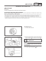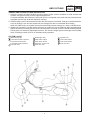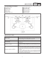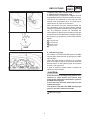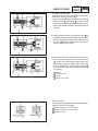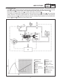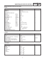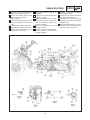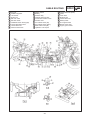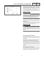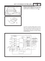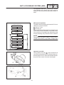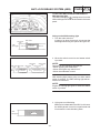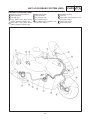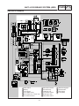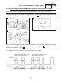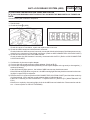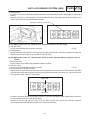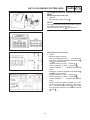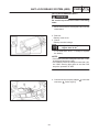
1
FOREWORD This Supplementary Service Manual has been prepared to introduce new service and data for the YP250A ’99. For complete service information procedures it is necessary to use this Supplementary Service Manual together with the following manual. YP250 SERVICE MANUAL: 4UC-AE1 YP250 (J) SUPPLEMENTARY SERVICE MANUAL: 4UC-AE2 YP250D SUPPLEMENTARY SERVICE MANUAL: 5DF-AE1 YP250A ’99 SUPPLEMENTARY SERVICE MANUAL 1998 by Yamaha Motor Co., Ltd. First Edition, July 1998 Any reproduction or unauthorized use without the written permission of Yamaha Motor Co., Ltd. is expressly prohibited. EB001000 NOTICE This manual was produced by the Yamaha Motor Company primarily for use by Yamaha dealers and their qualified mechanics. It is not possible to include all the knowledge of a mechanic in one manual, so it is assumed that anyone who uses this book to perform maintenance and repairs on Yamaha scooter has a basic understanding of the mechanical ideas and the procedures of scooter repair. Repairs attempted by anyone without this knowledge are likely to render the scooter unsafe and unfit for use. Yamaha Motor Company, Ltd. is continually striving to improve all its models. Modifications and significant changes in specifications or procedures will be forwarded to all authorized Yamaha dealers and will appear in future editions of this manual where applicable. NOTE: Designs and specifications are subject to change without notice. IMPORTANT INFORMATION Particularly important information is distinguished in this manual by the following notations. The Safety Alert Symbol means ATTENTION! BECOME ALERT! YOUR SAFETY IS INVOLVED! WARNING CAUTION: NOTE: Failure to follow WARNING instructions could result in severe injury or death to the scooter operator, a bystander or a person inspecting or repairing the scooter. A CAUTION indicates special precautions that must be taken to avoid damage to the scooter. A NOTE provides key information to make procedures easier or clearer. YP002000 HOW TO USE THIS MANUAL MANUAL ORGANIZATION This manual consists of chapters for the main categories of subjects. (See “Illustrated symbols”) 1st title 1 : This is the title of the chapter with its symbol on the upper right corner of each page. 2nd title 2 : This title indicates the section of the chapter and only appears on the first page of each section. It is located in the upper left corner of the page. 3rd title 3 : This title indicates a sub-section that is followed by step-by-step procedures accompanied by corresponding illustrations. EXPLODED DIAGRAMS To heps identify parts and clarify procedure steps, there are exploded diagrams at start of each removal and disassembly section. 1. An easy-to-see exploded diagram 4 is provided for disassembly and assembly jobs. 2. Numbers 5 are given in the order of jobs in the exploded diagram. A number that is enclosed by a circle indicates a disassembly step. 3. An explanation of jobs and notes is presented in an easy-to-read way by the use of symbol marks 6 . The meanings of the symbol marks are given on the next page. 4. A job instruction chart 7 accompanies the exploded diagram, providing the order of jobs, names of parts, notes in jobs, etc. 5. For jobs requiring more information, the step-by-step format supplements 8 are given in addition to the exploded diagram and the job instruction chart. 2 1 4 5 8 6 6 7 3 EB003000 1 GEN INFO 3 2 ILLUSTRATED SYMBOLS SPEC Illustrated symbols 1 to 9 are designed as thumb tabs to indicate the chapter’s number and content. 4 INSP ADJ ENG 5 6 COOL CARB 7 ELEC Illustrated symbols 10 to 17 are used to identify the specifications appearing in the text. 10 9 TRBL SHTG 11 12 13 14 16 10 11 12 13 14 15 16 17 17 18 19 20 21 22 23 24 General information Specifications Periodic inspection and adjustment Engine Cooling system Carburetion Chassis Electrical Troubleshooting 8 CHAS 15 1 2 3 4 5 6 7 8 9 25 Possible to maintain with engine mounted Filling fluid Lubricant Special tool Tightening Wear limit, clearance Engine speed Ω, V, A Illustrated symbols 18 to 23 in the exploded diagrams indicate the types of lubricants and lubrication points. 18 19 20 21 22 23 Apply engine oil Apply gear oil Apply molybdenum disulfide oil Apply wheel bearing grease Apply lightweight lithium-soap base grease Apply molybdenum disulfide grease Illustrated symbols 24 to 25 in the exploded diagrams indicate the where to apply locking agent 24 and when to install new parts 25 . 24 Apply locking agent (LOCTITE) 25 Use new one CONTENTS GENERAL INFORMATION . . . . . . . . . . . . . . . . . . . . . . . . . . . . . . . . . . . . . . . . ABS OUTLINE . . . . . . . . . . . . . . . . . . . . . . . . . . . . . . . . . . . . . . . . . . . . . . . . HU OPERATION TEST WHILE ABS IS WORKING . . . . . . . . . . . . . YAMAHA ABS PROVIDES 3 MAIN ADVANTAGES . . . . . . . . . . . . . SYSTEM LAYOUT . . . . . . . . . . . . . . . . . . . . . . . . . . . . . . . . . . . . . . . . . TOTAL SYSTEM BLOCK DIAGRAM . . . . . . . . . . . . . . . . . . . . . . . . . . COMPOSITION OF PARTS . . . . . . . . . . . . . . . . . . . . . . . . . . . . . . . . . COMPOSITION AND OPERATION OF PARTS . . . . . . . . . . . . . . . . SYSTEM OPERATION . . . . . . . . . . . . . . . . . . . . . . . . . . . . . . . . . . . . . CAUTION FOR OPERATION . . . . . . . . . . . . . . . . . . . . . . . . . . . . . . . . SPECIAL TOOLS . . . . . . . . . . . . . . . . . . . . . . . . . . . . . . . . . . . . . . . . . . . . . 1 1 1 3 3 4 4 5 10 13 14 SPECIFICATIONS . . . . . . . . . . . . . . . . . . . . . . . . . . . . . . . . . . . . . . . . . . . . . . . . GENERAL SPECIFICATIONS . . . . . . . . . . . . . . . . . . . . . . . . . . . . . . . . . . . MAINTENANCE SPECIFICATIONS . . . . . . . . . . . . . . . . . . . . . . . . . . . . . . ENGINE . . . . . . . . . . . . . . . . . . . . . . . . . . . . . . . . . . . . . . . . . . . . . . . . . . CHASSIS . . . . . . . . . . . . . . . . . . . . . . . . . . . . . . . . . . . . . . . . . . . . . . . . . ELECTRICAL . . . . . . . . . . . . . . . . . . . . . . . . . . . . . . . . . . . . . . . . . . . . . CABLE ROUTING . . . . . . . . . . . . . . . . . . . . . . . . . . . . . . . . . . . . . . . . . . . . . 15 15 17 17 17 17 18 CHASSIS . . . . . . . . . . . . . . . . . . . . . . . . . . . . . . . . . . . . . . . . . . . . . . . . . . . . . . . . ANTI-LOOK BRAKE SYSTEM . . . . . . . . . . . . . . . . . . . . . . . . . . . . . . . . . . TERMS EXPLANATION . . . . . . . . . . . . . . . . . . . . . . . . . . . . . . . . . . . . BRAKE FORCE AND THE VEHICLE STABILITY . . . . . . . . . . . . . . . WHEEL SLIP AND THE HYDRAULIC CONTROL . . . . . . . . . . . . . . ABS OPERATION AND THE VEHICLE CONTROL . . . . . . . . . . . . . ELECTRONICS ABS FEATURE . . . . . . . . . . . . . . . . . . . . . . . . . . . . . ABS COMPONENTS FUNCTION . . . . . . . . . . . . . . . . . . . . . . . . . . . . HYDRAULIC UNIT (HU) . . . . . . . . . . . . . . . . . . . . . . . . . . . . . . . . . . . . OTHER ABS MECHANISM COMPONENTS . . . . . . . . . . . . . . . . . . . ABS TROUBLESHOOTING OUTLINE . . . . . . . . . . . . . . . . . . . . . . . . ABS PARTS LOCATION CHART . . . . . . . . . . . . . . . . . . . . . . . . . . . . . ABS CONNECTOR LOCATION CHART . . . . . . . . . . . . . . . . . . . . . . ABS CIRCUIT DIAGRAM . . . . . . . . . . . . . . . . . . . . . . . . . . . . . . . . . . . BASIC INSTRUCTION FOR TROUBLESHOOTING . . . . . . . . . . . . BASIC PROCESS FOR TROUBLESHOOTING . . . . . . . . . . . . . . . . ABS TROUBLESHOOTING . . . . . . . . . . . . . . . . . . . . . . . . . . . . . . . . . [A] MALFUNCTION CHECK BY THE ABS WARNING LIGHT . . . . [B] DETAIL CHECK OF MALFUNCTION . . . . . . . . . . . . . . . . . . . . . . [B-1] WARNING LIGHT DOES NOT GO ON . . . . . . . . . . . . . . . . . . . [B-2] WARNING LIGHT REMAINS GOING ON . . . . . . . . . . . . . . . . . [B-3] WARNING LIGHT KEEPS FLASHING . . . . . . . . . . . . . . . . . . . [B-4] MALFUNCTION CHECK BY THE ABS SELF DIAGNOSIS (PAST MALFUNCTION) . . . . . . . . . . . . . . . . . . . . . . . . . . . . . . . . . . . . [B-5] MALFUNCTION CHECK BY THE ABS SELF DIAGNOSIS (PRESENT MALFUNCTION) . . . . . . . . . . . . . . . . . . . . . . . . . . . . . . . . [C] SUPPOSING THE MALFUNCTION CAUSE AND POSITION . 27 27 27 28 29 29 30 31 34 35 37 39 40 41 42 43 44 44 44 44 44 44 45 46 47 [C-1] ONLY ABS WARNING LIGHT DOES NOT GO ON WHEN THE MAIN SWITCH IS TURNED ON . . . . . . . . . . . . . . . . . . . . . . . . . [C-2] ABS WARNING LIGHT AND ALL OTHER INDICATORS DO NOT GOES ON . . . . . . . . . . . . . . . . . . . . . . . . . . . . . . . . . . . . . . . . [C-3] ABS WARNING LIGHT KEEPS FLASHING . . . . . . . . . . . . . . . [C-4] ABS WARNING LIGHT FLASHES EVERY 0.5 SECOND . . . [C-5] DIAGNOSIS BY THE MALFUNCTION CODE . . . . . . . . . . . . . ECU AND FAIL SAFE RELAY . . . . . . . . . . . . . . . . . . . . . . . . . . . . . . . [D-1] MAINTENANCE FOR ECU . . . . . . . . . . . . . . . . . . . . . . . . . . . . . [D-2] MAINTENANCE OF THE ABS FAIL-SAFE RELAY . . . . . . . . . FRONT WHEEL SENSOR AND SENSOR ROTOR . . . . . . . . . . . . . [D-3] MAINTENANCE OF THE FRONT WHEEL SENSOR AND SENSOR ROTOR . . . . . . . . . . . . . . . . . . . . . . . . . . . . . . . . . . . . . . . . . . REAR WHEEL SENSOR AND SENSOR ROTOR . . . . . . . . . . . . . . [D-4] MAINTENANCE OF THE REAR WHEEL SENSOR AND SENSOR ROTOR . . . . . . . . . . . . . . . . . . . . . . . . . . . . . . . . . . . . . . . . . . HYDRAULIC UNIT (HU) . . . . . . . . . . . . . . . . . . . . . . . . . . . . . . . . . . . . [D-5] MAINTENANCE OF THE HYDRAULIC UNIT (HU) . . . . . . . . . AIR BLEEDING . . . . . . . . . . . . . . . . . . . . . . . . . . . . . . . . . . . . . . . . . . . . CHECK THE OPERATION OF HYDRAULIC UNIT ACCORDING TO THE DECOMPRESSION . . . . . . . . . . . . . . . . . . . [D-6] FINAL CHECK . . . . . . . . . . . . . . . . . . . . . . . . . . . . . . . . . . . . . . . . [D-6-1] CHECKING THE RESERVOIR TANK FLUID LEVEL . . . . . [D-6-2] RECHECKING THE ASSEMBLY STATUS OF WHEEL SENSORS . . . . . . . . . . . . . . . . . . . . . . . . . . . . . . . . . . . . . . . . [D-6-3] HU OPERATION TEST 2 . . . . . . . . . . . . . . . . . . . . . . . . . . . . . [D-6-4] DELETING THE MALFUNCTION CODE . . . . . . . . . . . . . . . [D-6-5] TRIAL RUN . . . . . . . . . . . . . . . . . . . . . . . . . . . . . . . . . . . . . . . . . REAR SHOCK ABSORBER AND SWING ARM . . . . . . . . . . . . . . . . . . . YP250A ’99 WIRING DIAGRAM 47 48 48 49 50 60 61 62 64 65 69 70 72 73 78 78 78 79 79 80 82 83 84 ABS OUTLINE GEN INFO GENERAL INFORMATION ABS OUTLINE Introduction YP250A is equipped with the ABS (Anti-lock Brake System). HU OPERATION TEST WHILE ABS IS WORKING With the scooter stopped, YP250A allows a driver to test the performance of brake lever reaction force which is generated when the ABS operates. There are two methods for the HU operation test, but this section describes only about the HU operation test 1. HU operation test 1: Equal reaction force to the time of ABS operation is generated on the lever. HU operation test 2: Mainly performs when checking the function after the ABS system has been disassembled, adjusted and serviced. Refer to [D-6-3] HU operation test 2. HU operation test 1 1. Turn the main switch off. 2. Remove the protective cap and insert the test coupler adapter 1 into the test connector 2 . Test coupler adapter 90890-03149 NOTE: To access the test coupler, remove the lower panel of windscreen. 3. Turn the engine stop switch 1 off. 1 ABS OUTLINE GEN INFO 4. Turn the main switch on. NOTE: Wait until the ABS warning light goes off after turning the main switch on.(2 seconds) 5. Turn on the starter switch 1 for longer than 4 seconds. CAUTION: Do not grip the brake lever in this case. 6. After releasing the starter switch (OFF), apply the front brake lever. Reaction force is generated on the front brake lever 0.5 second later and lasts about 2 seconds. 7. If the reaction force of front brake lever is lost, apply the rear brake lever while applying the front brake lever. Reaction force is generated on the front brake lever 0.5 second later and lasts about 2 seconds. 8. Turn the main switch off. 9. Remove the test coupler adapter from the test connector. 10. Turn the main switch on. 11. Set the engine stop switch to RUN position. 2 ABS OUTLINE GEN INFO YAMAHA ABS PROVIDES 3 MAIN ADVANTAGES 1. Securely controls the wheel locking at urgent braking under various conditions of road surface and weather, and gives full play to tires’ original performance. For higher reliability, the electronic control unit (ECU) is composed of the main and sub processors and equipped with the high level self diagnostic function. 2. Smooth braking can be also performed when the ABS system is activated. Change of chassis behavior such as pitching is few and this system will not damage the rider’s comfortable drive feeling. When the ABS works, the system informs the brake fluid pressure change to a rider via brake levers. 3. Weight of the hydraulic unit (HU) which is the main of system is 2.2 kg for YAMAHA ABS. We designed to gather the mass by locating this unit at the central portion of scooter. Since the wheel assembly (wheel sensor) also has extremely lightweight structure, the vehicle’s weight gives no damage to the mobility which YP250A provides such as an excellent safety operation. SYSTEM LAYOUT 1 ABS warning light 2 Front / Rear master cylinders Front / Rear brake levers Front / Rear brake switches 3 Fail-safe relay 4 5 6 7 8 Brake light relay Rear brake caliper Rear wheel sensor Electronic control unit Rear disc rotor 3 9 10 11 12 Hydraulic unit Front brake caliper Front wheel sensor Front disc rotor ABS OUTLINE GEN INFO TOTAL SYSTEM BLOCK DIAGRAM 1 2 3 4 5 6 7 Rear master cylinder Hydraulic unit Silencer chamber Hydraulic pump Electric motor Buffer chamber Hydraulic control valve 8 9 10 11 12 13 14 Front master cylinder Rear brake caliper Front brake caliper Electronic control unit Rear wheel sensor Front wheel sensor ABS warning light COMPOSITION OF PARTS Component Function Wheel sensor Detects each wheel rotation pulse of front and rear wheels and inputs them to the electronic control unit. ABS warning light Warns the ABS system failure to the rider. Fail-safe relay Supplies the power to the solenoid valve and motor of hydraulic unit. Hydraulic unit (HU) Controls the brake fluid pressure of front and rear wheels according to the output signal sent from the electronic control unit. Electronic control unit (ECU) Outputs the operation signal to the hydraulic unit so that the unit controls matching the road conditions according to the wheel rotation pulses transmitted from front and rear wheel sensors. In case of ABS system failure, the unit activates the ABS warning light and shuts off the power to hydraulic unit and deactivates the ABS operation. 4 ABS OUTLINE GEN INFO COMPOSITION AND OPERATION OF PARTS 1. Wheel sensor and sensor ring A wheel sensor is composed of magnet and coil and installed with front and rear wheels’ housings. The sensor ring attached to front and rear cast wheels have 36 serration each. The front end of wheel sensor is close to the serration. When the sensor rotor with serration rotates, the flux generation from the wheel sensor magnet changes to generate the alternating voltage in the coil. The electronic control unit calculates the wheel speed by detecting the repeating times per unit period since this alternating voltage changes the frequency proportioning to the wheel rotation speed. 1 2 3 4 At high speed At low speed Wheel sensor Sensor rotor 2. ABS warning light If the failure occurred in the ABS system, the ABS warning light alerts the rider by going on the ABS warning light. When the main switch is turned on, the system goes on the light for about 2 seconds to check the disconnection of ABS warning light and system function, then it goes off. It goes on while the starter switch is pushed to check the disconnection. CAUTION: If the rear wheel is raced by lifting with the centerstand or other means, the system may judge as the malfunction to flashes or goes on the ABS warning light. In this case, turn the main switch off once and restart the engine. The system is normal if the ABS warning light goes on and off in about 2 seconds. 1 ABS warning light 5 ABS OUTLINE GEN INFO 3. Hydraulic unit Hydraulic unit is composed of two pieces of hydraulic control valve (solenoid valve, flow control valve), buffer chamber, pump and silencer chamber, and one motor. It adjusts the front/rear wheel brake fluid pressure to control the wheel rotation condition according to the signal sent from the electronic control unit. 1 2 3 4 5 To rear brake master cylinder Silencer chamber Hydraulic pump Electric motor Buffer chamber 6 7 8 9 10 6 Hydraulic control valve To front brake master cylinder To the rear brake caliper To the electronic control unit To the front brake caliper ABS OUTLINE GEN INFO Hydraulic control valve Hydraulic control valve is composed of the solenoid valve and flow control valve. 1) When the normal brake is applied, the solenoid valve closes 2 , the spool 3 of flow control valve does not move and the hydraulic line between the master cylinder and brake caliper is opened. 2) While the ABS works, the solenoid valve 2 is supplied the power to open when the electronic control unit signals the pressure reduction and the spool 3 of flow control valve is moved toward to the solenoid valve. 3) When the electronic control unit stops the signal of pressure reduction, the solenoid valve 2 closes and pressurizing starts again. Repressurizing while the ABS works controls the flow of brake fluid by the movement of spool 3 of flow control valve, and provides slow pressure rising. 1 2 3 4 Orifice Solenoid valve Spool Flow control valve Buffer chamber Accumulates the decompressed brake fluid temporarily while the ABS works. 1 Buffer chamber (in normal state) 2 Buffer chamber (decompressing) 3 Raise the piston 7 ABS OUTLINE GEN INFO 4. Electronic control unit Relation of the input signal and output signal is shown in the diagram. The circuit receives the signals from wheel sensors, processes them according to the programs in the microcomputer and outputs the control signal to the hydraulic unit and ABS warning light. Electronic control unit (ECU) Power Voltage regulator Memory Front brake switch signal Rear brake switch signal Stop lamp signal Solenoid motor Front brake switch circuit Rear brake switch circuit Motor monitor circuit Solenoid drive circuit Fail-safe relay drive circuit Main CPU (Main microcomputer) Motor Hydraulic unit (HU) Solenoid Motor relay Motor relay drive circuit Warning light drive circuit Brake light circuit Solenoid valve ABS warning light Operation mode switching circuit Starter switch signal Starter switch Starter switch circuit Fault code output circuit Checker Front wheel sensor Rear wheel sensor Front wheel speed output circuit Digital conversion circuit Sub CPU (Sub microcomputer) 8 Speedometer Fail-safe relay ABS OUTLINE GEN INFO 5. Fail-safe relay Fail-safe relay controls the power of hydraulic unit and it is located inside of the tail cover. 1 Fail safe relay Composition and operation Fail-safe relay is composed of the solenoid relay 1 and motor relay 2 . Solenoid relay is continued when the electronic control unit outputs the system start signal. Accordingly, the solenoid valve 3 is activated when the electronic control unit signals the decompression. In case of malfunction, the solenoid relay is turned off and the solenoid valve is deactivated. This makes it impossible to reduce the hydraulic pressure and resumes normal braking. Motor relay is also continued by the signal of electronic control unit and starts the motor simultaneously when the ABS pressure reduction begins. When the solenoid is turned off, the motor relay is also turned off, therefore the motor stops its operation in case of malfunction. 1 2 3 4 5 Solenoid relay Motor relay Solenoid valve Electric control unit Pomp motor relay coil 6 7 8 9 10 Pump motor monitor ABS warning light Fail-safe relay coil Front solenoid Rear solenoid 9 11 Power 12 Fail-safe relay 13 Hydraulic unit GEN INFO ABS OUTLINE SYSTEM OPERATION ABS system’s fluid pressure circuit has the 2 lines of front wheel and rear wheel systems. In this section, we describe about one system of a front wheel. Normal brake (ABS not activated) Port D 12 of the solenoid valve is closed since the control signal from the electronic control unit is not sent to the hydraulic unit. A 8 and B 10 ports of flow control valve spool are opened. Accordingly, when a rider apply the brake lever and the master cylinder hydraulic pressure rises, the brake fluid is directed in the line from Port A 8 to Port B 10 then to brake caliper. At this time, inlet and outlet check valves of pump close the lines and brake fluid is not sent. Therefore, master cylinder directly pressurizes the brake caliper while braking normally. When the brake lever is released next, the brake fluid in the brake caliper returns then to the master cylinder via Port B 10 , Port A 8 . 1 Brake master 2 3 4 5 6 7 8 9 10 10 cylinder Brake switch Silencer chamber Motor Pump Buffer chamber Flow control valve Port A Spool Port B 11 12 13 14 15 16 17 18 19 20 Orifice Port D Solenoid valve Port C Brake caliper Electronic control unit ABS warning light Brake fluid pressure Time Repressurizing GEN INFO ABS OUTLINE At the time of urgent braking (When ABS works) 1) Decompressed state When the wheel is almost locked, the solenoid valve’s port D 12 opens by the “decompression” signal from the electronic control unit. At this time, the spool 9 of flow control valve compresses the return valve to close the port B 10 . Brake fluid which has entered through port A 8 is restricted by the orifice 11 . Accordingly, the brake fluid from the brake caliper is sent in the line of Port C 14 , Port D 12 then to the buffer chamber 6 . The brake caliper fluid pressure is now reduced. Brake fluid which has been stored in the buffer chamber is pumped by the fluid pressure pump interlocked with motor and returned to the master cylinder. 1 Brake master 2 3 4 5 6 7 8 9 10 11 cylinder Brake switch Silencer chamber Motor Pump Buffer chamber Flow control valve Port A Spool Port B 11 12 13 14 15 16 17 18 19 20 Orifice Port D Solenoid valve Port C Brake caliper Electronic control unit ABS warning light Brake fluid pressure Time Repressurizing GEN INFO ABS OUTLINE 2) Pressurized state Port D 12 of solenoid valve closes according to the “increase pressure” signal from the electronic control unit. Also, spool 9 of flow control valve compresses the return spring to close the port B 10 . Brake fluid entered through port A 8 is further restricted by the orifice 11 . Accordingly, the brake fluid in master cylinder is sent in the line of Port A 8 , Port C 14 then to the brake caliper. However, the brake is pressurized at a constant speed regardless of the brake fluid pressure level since the port A’s 8 restriction changes so that the constant pressure difference is maintained between A 21 and B 22 chambers of flow control valve. 1 Brake master 2 3 4 5 6 7 8 9 10 11 12 cylinder Brake switch Silencer chamber Motor Pump Buffer chamber Flow control valve Port A Spool Port B Orifice 12 13 14 15 16 17 18 19 20 21 22 Port D Solenoid valve Port C Brake caliper Electronic control unit ABS warning light Brake fluid pressure Time Repressurizing Chamber A Chamber B ABS OUTLINE GEN INFO CAUTIONS FOR OPERATION The YAMAHA ABS applies the double system control type with the independent hydraulic system for the front and rear wheels respectively. Accordingly, the brake operation is the same as usual scooters providing the right hand brake lever to be used for the front wheel and left hand brake lever for the rear wheel. When the locking tendency of wheels due to urgent brake is detected on each wheel, the independent hydraulic control is performed by each brake hydraulic system. The YAMAHA ABS controls the hydraulic pressure by electronic controls. With the main switch turned on, when the electronic control unit always operates the wheel’s locking movement and checks the system function simultaneously. If the failure such as a malfunction occurs to the ABS or peripheral electric system, the scooter automatically shifts to apply the normal brake function. If the ABS warning light goes on: When the main switch is turned on, the ABS warning light goes on for about 2 seconds. While pressing the starter switch, the ABS warning light and engine oil level warning light goes on. If the ABS warning light goes on during the riding, stop the scooter at the safe place, stop the engine and turn the main switch off. Turn the main switch on again. It is normal if the ABS warning light goes on and off in about 2 seconds. Even if the ABS warning light keeps going on and will not go off, or it goes on again after riding, the vehicle’s performance as a normal brake is still maintained. If the rear wheel is raced, the ABS system may judge as the malfunction to flashing or goes on the ABS warning light. In this case, turn the main switch off once. Then, turn on again. The ABS system is normal if the ABS warning light goes on and off in about 2 seconds. ABS works normal when the ABS warning light flashings. ABS function: ABS is not designed to shorten the braking distance or improve the cornering performance. The braking distance may become longer in comparison with scooters without ABS depending on the road condition, keep a lower speed and safe distance between yourself and the other vichicls. It is basic for a scooter to brake while driving straight. Sudden braking while cornering affects the motion characteristics of chassis. Avoid it. Brake system in which the hydraulic control has been performed by the ABS system alerts a rider that the wheel had an inclination to lock by returning the reaction force to the brake lever. In this case, this condition is a sign that the grip between road surface and tires had come close to the limit point. The rear wheel’s locking state* which occurs when the strong engine brake is applied on the slippery road is beyond the ABS control range. In these cases, drive the vehicle carefully. The ABS does not work when the main switch is turned off. It becomes the normal braking function. * Locking state: By braking stronger than the tires’ gripping force, the chassis moves forward but the wheels do not rotate. 13 SPECIAL TOOLS GEN INFO EB104000 SPECIAL TOOLS The following special tools are necessary for complete and accurate tune-up and assembly. Use only the appropriate special tools as this will help prevent damage caused by the use of inappropriate tools or improvised techniques. When placing an order, refer to the list provided below to avoid any mistakes. Tool No. Tool name/Function Test coupler adaptor 90890-03149 This tool is used to check the ABS diagnosis. 14 Illustration GENERAL SPECIFICATIONS SPEC SPECIFICATIONS GENERAL SPECIFICATIONS Model Model code: YP250A 5DF3 (except for CH) 5DF4 (for CH) Dimensions: Overall length Overall width Overall height Seat height Wheelbase Minimum ground clearance Minimum turning radius 2,110 mm ,780 mm 1,330 mm ,700 mm 1,500 mm ,115 mm 2,600 mm Basic weight: With oil and full fuel tank 169 kg Transmission: Primary reduction system Primary reduction ratio Secondary reduction system Secondary reduction ratio Transmission type Operation Single speed automatic Helical gear 40/15 (2.667) Sper gear 38/15 (2.533) Single speed automatic (V-belt type) Centrifugal automatic type 2.34 0.82 : 1 Tire pressure (cold tire): Maximum load-except motorcycle Loading condition A* front rear Loading condition B* front rear High-speed riding front rear Brake: Brake control device Front brake type operation Rear brake type operation 186 kg 0 90 kg 175 kPa (1.75 kg/cm2, 1.75 bar) 200 kPa (2.0 kg/cm2, 2.0 bar) 90 186 kg 200 kPa (2.0 kg/cm2, 2.0 bar) 225 kPa (2.25 kg/cm2, 2.25 bar) 200 kPa (2.0 kg/cm2, 2.25 bar) 250 kPa (2.5 kg/cm2, 2.5 bar) ABS Single disc brake Right hand operation Single disc brake Left hand operation * Load is the total weight of cargo, rider, passenger, and accessories. 15 GENERAL SPECIFICATIONS Model Bulb wattage quantity: Headlight Marker light Tail/brake light Flasher light Meter light High beam indicator light Oil indicator light Turn indicator light ABS warning light License light YP250A 12 V 60 W/55 W 12 V 5 W 1 12 V 5 W/21 W 12 V 21 W 4 12 V 1.7 W 4 12 V 1.7 W 1 12 V 1.7 W 1 12 V 3.4 W 2 LED 1 12 V 5 W 1 16 1 1 SPEC MAINTENANCE SPECIFICATIONS SPEC MAINTENANCE SPECIFICATIONS ENGINE Item Standard Limit Carburetor: Type I.D. mark Ventuly outside diameter Main jet Main air jet Jet needle Throttle valve size Pilot air jet Needle jet Pilot outlet Pilot jet Bypass Pilot screw Valve seat size Starter jet 1 Starter jet 2 Float height Engine idle speed Intake vacuum Oil temperature Cooling water temperature Y28V-1A 4UC 03 [4UD 03 (CH)] ø 28 # 130 ø 0.9 5D32-3/5 11_ ø 1.2 # 85 ø 0.8 # 44 0.7 3 1 7/8 [1 5/8 (CH)] 1.4 ø 0.45 [ø0.47 (CH)] ø 0.5 27 mm 1,350 X 1,450 r/min 220 X 260 mmHg 65 X 75_C 80_C SSS SSS SSS SSS SSS SSS SSS SSS SSS SSS SSS SSS SSS SSS SSS SSS SSS SSS SSS SSS Item Standard Limit Rear disc brake: Type Disc outside diameter thickness Pad thickness Master cylinder inside diameter Caliper cylinder outside diameter Brake fluid type Single 230 5.0 mm 5.3 mm 11 mm 22.2 + 22.2 mm DOT #4 SSS SSS 0.8 mm SSS SSS SSS Standard limit Fuse 20 A 3A 30 A 5A 20 A 3A 30 A 5A SSS SSS SSS SSS SSS SSS SSS SSS SSS (M.J) (M.A.J) (J.N) (Th.V) (P.A.J.1) (N.J) (P.O) (P.J) (B.P) (P.S) (V.S) (G.S.1) (G.S.2) (F.H) CHASSIS ELECTRICAL Item Circuit breaker: Type MAIN FAN ABS motor ABS Reserve 1 pc. 1 pc. 1 pc. 1 pc. 1 pc 1 pc. 1 pc. 1 pc. 17 CABLE ROUTING SPEC CABLE ROUTING 1 2 3 4 5 6 7 8 9 Front wheel sensor lead Wireharness (ABS) Rear wheel sensor lead Carburetor drain hose Carburetor coolant drain hose Carburetor air ventilation hose Fail safe relay Brake light relay Electronic control unit (ECU) 10 11 12 13 14 15 16 17 18 Rear wheel sensor Crankcase Over flow hose (fuel filler) Hydraulic unit Down tube Wireharness Steering head pipe Throttle cable Crankcase breather hose 18 A Route the rear brake hose through the guide on the handlebar holder. B Fasten the wireharness to the stay with a plastic band. Refer to fig D. C Fasten the throttle cables and wireharness to the down tube with a plastic band. Refer to fig A. CABLE ROUTING D Align the mark on the brake hoses with clamp, and clamp them. E Fasten the throttle cable to the frame with a plastic band. Refer to fig B. F Route the fuel tank over flow hose through the clamp on inside of the frame. G Lower throttle cable is pull side. H Upper throttle cable is push side. I Fasten the wireharness with a steel clamp on the frame. J Route the rear wheel sensor as illustration. K Route the rear wheel sensor lead through the guide. L Route the carburetor air ventilation hose, carburetor coolant drain hose and carburetor drain hose through the guide. M Route the carburetor drain hose through the guide. N Route the over flow hose (fuel filler) and hydraulic unit drain hose through the guide. 19 SPEC O Position the connector of plastic band as illustration. P Position the connector of the plastic band inside of the line. Q Route the rear wheel sensor lead through the front of the crankcase breather hose. R Align the white tape on the wireharness with the steel clamp on the frame, and fasten them. CABLE ROUTING 1 2 3 4 5 6 7 8 9 10 Box light Rectifier / regulator Fuel sender Ignition coil Roll over valve Seat lock cable Handlebar switch lead (right) Front brake switch lead Front brake hose Reservoir tank hose 11 12 13 14 15 16 17 18 19 20 Starter switch Battery Flasher relay Coolant reservoir tank Crankcase breather hose Air filter case Front brake hose (IN) Front brake hose (OUT) Rear brake hose (IN) Hydraulic unit coupler 20 21 22 23 24 25 26 27 28 29 SPEC Rear brake hose (OUT) Igniter Down tube Wireharness Rear brake hose Battery leads AC magneto lead Starter motor lead Engine ground lead CABLE ROUTING A Route the box light lead through from the outside of the frame to the inside of the pipe. B Connect the taillight lead and wireharness on the mudguard. C Fasten the fuel sender lead to the pipe with a plastic clamp. D Fasten the fuel sender lead and auto choke lead with a steel clamp on inside of the frame. E Fasten the seat box light switch lead to the hinge with a plastic locking tie. Route the plastic locking tie into the hole and under the projection of hinge. F Route the box switch lead under the projection of fuel tank hinge. G Route the box switch lead from outside of the fuel tank over flow hose to inside of the pipe. H Fasten the electronic control unit leads (3 lines) with a plastic band. 21 SPEC I Route the seat lock cable through the pipe, and align the mark of seat lock cable with the pipe end. J Fasten the wireharness and seat lock cable with a steel band on the frame. K Position the junction of the thermo switch lead inside of the scooter. L Align the location tape with the steel clamp on the frame, and fasten them. CABLE ROUTING M Fasten the wireharness, seat lock cable and pipe with a steel clamp on the frame. N Fasten the front wheel sensor lead and front brake hose with a plastic clamp. Position the clamp (location of the front wheel sensor) to front of the upper clamp and another clamps to outside. O Route the front wheel sensor lead between the caliper and caliper bolt. Do not route as dotted line. SPEC P Route the front wheel sensor lead U Fasten the wireharness to the through the guide. frame with a plastic band. Q Fasten the pipe with a steel clamp V Route the brake hose, wireharon the frame. ness and battery leads through the R Fasten the fan motor lead, sideguide. stand switch lead and starter W Fasten the battery leads and wireswitch lead to the frame with a harness with a steel clamp on the plastic band. frame. S Route the wireharness over the X Fasten the wireharness with a rear brake hose. steel clamp on the frame. T Route the coolant reservoir tank Y Position the connector of plastic over flow hose through the guide band as illustration. on the inside of the frame. Z Clearance: 1 mm or more 22 CABLE ROUTING 1 2 3 4 5 6 7 8 9 10 11 12 Seat lock Air filter case Engine ground lead Crankcase breather hose Fuel hose Vacuum hose Sidestand switch lead Fan motor lead Fuel tank over flow hose Reservoir tank breather hose Starting circuit cutoff relay Auto choke lead 13 14 15 16 17 18 AC magneto lead Starter motor lead Seat lock cable Fuel pump Fuel tank Hydraulic unit A Route the hydraulic unit drain hose under the coolant hose. B Fasten the fuel tank over flow hose with a steel clamp on the frame. 23 SPEC C Fasten the sidestand switch lead with a steel clamp on the frame. D Route the thermo switch lead outside of the frame. E Fasten the wireharness to the frame with a plastic band. F Route the battery positive lead as illustration. G Fasten the thermo switch lead and fan motor lead with a steel clamp on the frame. CABLE ROUTING H Fasten the sidestand switch lead and battery positive lead with a steel clamp on the frame. I Fasten the sidestand switch lead with a plastic clamp. J Route the battery negative lead through the front and lower side of the flasher relay. K Fasten the wireharness, AC magneto lead, starter motor lead and engine ground lead with a steel clamp on inside of the frame. L Fasten the AC magneto lead, starter motor lead and engine ground lead with a steel clamp on the engine bracket. M Route the crankcase breather hose into the hole of air filter case. N Route the fuel hose over the vacuum hose. O Position the end of the clip to outside. P Fasten the front wheel sensor and electronic control unit lead to the frame with a plastic band. 24 SPEC Q Install the fuse box to the stay on the frame. R Fasten the front wheel sensor, fuse lead and electronic control unit lead to the frame with a plastic band. S Do not fasten the fuel tank over flow hose with a plastic band. CABLE ROUTING 1 2 3 4 5 6 7 8 9 10 11 12 Front turn signal light (right) Front turn signal light (left) Handlebar switch lead (right) Front stop switch lead Seat lock cable Throttle cable Handlebar switch lead (left) Rear brake switch lead Handlebar under cover Stay Horn Front brake hose 13 14 15 16 17 18 19 Front wheel sensor Horn ABS test terminal Handlebar upper cover Handlebar Front turn signal light Grip heater lead (option) A Route the front wheel sensor through the guide on the frame. B Route the handlebar switch lead and front brake switch lead through the guide. 25 SPEC C Route the front brake hose through the right hole of the handlebar under cover. D Route the rear brake hose through the left hole of the handlebar under cover. E Fasten the handlebar switch lead (left) and rear brake switch lead to the handlebar with a plastic locking tie. Cut the end of locking tie at 5 mm or less. CABLE ROUTING F Route the handlebar switch (left) lead and rear brake switch lead through the left side of the speedometer cable. G Route the front wheel sensor through the guide. H Fasten the front brake hose with a brake hose holder. I Fasten the headlight lead, horn lead and front wheel sensor lead with a steel clamp on the stay. J Route the handlebar switch (left) lead through the front side of the handlebar under cover. 26 SPEC ANTI-LOCK BRAKE SYSTEM (ABS) CHAS CHASSIS ANTI-LOCK BRAKE SYSTEM The YAMAHA ABS is the electronic control system applying the 2 system control type with the independent hydraulic system for the front and rear wheels respectively. Accordingly, the brake operation is the same as usual scooters providing the right hand brake lever to be used for the front wheel and left hand brake lever for the rear wheel. When the locking movement of wheels due to urgent braking is detected on each wheel, the independent hydraulic control is performed by each brake hydraulic system. TERMS EXPLANATION Wheel speed Rotation speed of front and rear wheels itself is the wheel speed. Chassis speed When the brake is applied, the wheel rotation is lowered and the chassis speed reduces. However, the chassis tends to travel forward by its inertia even though the wheel rotation is lowered. The speed of chassis itself is the chassis speed. Brake force This is the force to reduce the speed by braking. Wheel lock On a slippery road, if the brake was applied too strong the vehicle tends to run on, but the wheels stop rotating. This state is called a wheel lock. Side force This is the force to act on tires which supports the vehicle sideways. 27 ANTI-LOCK BRAKE SYSTEM (ABS) CHAS Slip ratio When the brake is applied, slipping occurs between tires and road surface, then the difference is made between the wheel speed and chassis speed. This is called a slip. Slip ratio is the value to show the rate of slipping and defined by the following formula. Slip ratio = Chassis speed – Wheel speed Chassis speed 100 (%) 0%: There is no slip between wheels and road surface providing the complete rotation of wheels. 100%: The wheel speed is “0”, i.e. the state of wheel locking. A BRAKE FORCE AND THE VEHICLE STABILITY When the brake pressure is increased, it brakes the wheel and the slip occurs between the tire and road surface to generate the brake force. The limit of this brake force is determined by the friction force between the tire and road surface and has a close relation with the state of slipping. Slipping state is shown by the slip ratio. Therefore, the side force has also a close relation with the slipping state . Figure A shows the relation of them. If the vehicle is braked while keeping the proper slip ratio, it is possible to gain the maximum brake force without losing the much side force. The ABS has a function which allows these tire characteristics to bring their ability into full play on the slippery or less-slippery road. (Figure B ) Friction force between the tire and road surface Brake force Side force Slip ratio(%) Friction force between the tire and road surface B Less slippery road surface Controlling zone Slippery road surface Slip ratio(%) 28 ANTI-LOCK BRAKE SYSTEM (ABS) CHAS WHEEL SLIP AND THE HYDRAULIC CONTROL The ABS computer calculates each wheel speed according to the rotation signal receiving from the front and rear wheel sensors. In addition, the computer calculates the vehicle travel speed and rate of speed reduction with wheels based on the wheel speed values. Differences between the travel speed and wheel speed of wheels calculated as above are equal to the wheel slip. When the wheel tends to lock, the wheel suddenly reduces its speed. When the slip of wheel and speed reduction rate of wheel exceeds the preset value, the ABS computer judges that the wheel is in the tendency to lock. If the slip is large and the wheel tends to lock (A point in the figure), the ABS computer decompresses the brake fluid of caliper and increases the pressure when the locking tendency disappears (B point in the figure). If slip is large and the wheel tends to lock (A point in the figure), the ABS computer executes the pressure reduction and increases the pressure when the locking tendency disappears (B point in the figure). Vehicle speed Wheel speed Pressurizing Decompressing Brake force ABS OPERATION AND THE VEHICLE CONTROL When the ABS is activated, it means that the wheel has a tendency to lock and the vehicle control is close to its limit. To recognize this vehicle condition, the brake lever is designed to generate the reaction force. NOTE: Reaction force to the brake lever while the ABS works is normal. 29 ANTI-LOCK BRAKE SYSTEM (ABS) Side force also reduces when the vehicle equipped with the ABS is braked as same as vehicles with ordinary brake system. Accordingly, sudden braking while cornering loses the vehicle’s stability regardless of ABS existence. It is not the ABS function to prevent the vehicle from slipping to sideways. Brake force Friction force between the tire and road surface CHAS Side force WARNING Slip ratio(%) It is basic for a scooter to brake while driving straight. Even the ABS equipped scooter cannot stop slipping sideways by losing its stability due to sudden brake while cornering. The function of ABS works to control the brake’s hydraulic pressure and prevent the wheel’s locking tendency. Accordingly, locking of wheels which may occur when the engine brake is applied on the slippery road is beyond the ABS control range. WARNING Even the ABS equipped scooter cannot prevent the locking tendency of wheels on the extremely slippery road caused by the engine brake. ELECTRONICS ABS FEATURE The YAMAHA ABS is the anti-lock brake system developed under the most advanced electronics technology. The control is processed with good response providing various travel conditions for scooters. The system also equipments the highly developed self diagnostic function and designed to return to the normal braking state by detecting the problem condition correctly even if the vehicle is struck by troubles. At the moment, the ABS warning light of meter panel alerts a drive by goes on. The YAMAHA ABS is designed to restore the trouble history in the memory allowing easy troubleshooting by reading the malfunction code. 30 ANTI-LOCK BRAKE SYSTEM (ABS) CHAS The ABS is composed of major components as follows. Front and rear wheels are equipped with sensors and sensor rotors respectively. 1 Wheel sensor and the sensor rotor 2 Electronic control unit (ECU) 3 Hydraulic unit (HU) 4 Fail-safe relay 5 ABS harness In addition, there are relevant parts such as the ABS warning light in the meter panel, the test connector of ABS harness in the cowling body. CAUTION: Care should be taken to handle the ABS components since they have been accurately adjusted and must be kept away from shocks and dirt. Among the ABS components, parts of the ECU, HU, wheel sensor and fail-safe relay cannot be disassembled. ABS COMPONENTS FUNCTION Wheel sensor and the sensor rotor Wheel sensor 1 detects the wheel rotation speed and works to send the wheel rotation signal to the ECU. It is composed of the permanent magnet and coil. For a front wheel, it is attached to the sensor housing 2 and to the crankcase for a rear wheel. Sensor rotor 3 is pressed in the inner side of wheel hub with front and rear wheels, then rotates together with the wheel. Sensor rotor has 36 serration inside and is installed close to the wheel sensor. Accordingly, the distance changes to the crest and bottom of teeth as the wheel rotates to generate the inductive electromotive force in the wheel sensor. Wheel rotation speed can be thus detected based on the frequency of this alternating voltage. 31 ANTI-LOCK BRAKE SYSTEM (ABS) CHAS Electronic control unit (ECU) Electronic control unit 1 controls the ABS and is installed inside the taillight unit. To protect from water invasion, it is enveloped by a cover 2 . As shown in the block diagram below, the ECU takes in the wheel sensor signals from front and rear wheels and also receives the signals from various monitor circuits. Two of main and sub microcomputers are installed in the ECU providing mutual monitoring. Electronic control unit (ECU) Power Voltage regulator Memory Front brake switch signal Rear brake switch signal Stop lamp signal Solenoid motor Front brake switch circuit Rear brake switch circuit Motor monitor circuit Solenoid drive circuit Fail-safe relay drive circuit Main CPU (Main microcomputer) Motor Hydraulic unit (HU) Solenoid Motor relay Motor relay drive circuit Warning light drive circuit Brake light circuit Solenoid valve ABS warning light Operation mode switching circuit Starter switch signal Starter switch Starter switch circuit Fault code output circuit Checker Front wheel sensor Rear wheel sensor Front wheel speed output circuit Digital conversion circuit Sub CPU (Sub microcomputer) 32 Speedometer Fail-safe relay ANTI-LOCK BRAKE SYSTEM (ABS) CHAS The operation result is confirmed by the monitor circuit. Based on the result, the control signals of hydraulic unit (HU) and fail-safe relay will be issued. ABS control operation The ABS control operation performed in ECU is divided into 2 parts as follows. Soft wear operation flow Turn the main switch on 1 Hydraulic control 2 Self diagnosis These operations will be performed repeating one time in every 8/1000 seconds. In the case of failure occurrence, it is stored in the malfunction code memory allowing easy find and check of failures. Initialize Self diagnosis (at static) NOTE: Depending on the type of failure, it will not be recorded in the memory. (e.g. battery voltage drop) Self diagnosis (at riding) Receive the signals 8 / 1000 seconds Control operation Judge of decompressing / pressurizing Hydraulic unit (HU) This hydraulic unit (HU) 1 is the component to control the hydraulic pressure of brake system under the signal of ECU, and located beside the battery box at the center of scooter central part. 33 ANTI-LOCK BRAKE SYSTEM (ABS) CHAS HYDRAULIC UNIT (HU) Hydraulic unit is composed of two pieces of hydraulic control valve (solenoid valve, flow control valve), buffer chamber, pump and silencer chamber, and one motor. It adjusts the front/rear wheel brake fluid pressure to control the wheel rotation condition according to the signal transmitted from the electronic control unit. 1 Rear master 2 3 4 5 6 7 8 9 10 11 cylinder Hydraulic unit Silencer chamber Hydraulic pump Electric motor Buffer chamber Hydraulic control valve Front master cylinder Rear brake caliper Front brake caliper Electronic control unit 12 Rear wheel sensor 13 Front wheel sensor 14 ABS warning light HU components Components of each system are five parts as follows. 1 Flow control valve 2 Solenoid valve 3 Buffer chamber 4 Hydraulic pump 5 Silencer chamber Flow control valve 1 works to keep the brake fluid flow at a constant flow rate while the ABS works. This valve also increases and decreases the brake fluid pressure together with the solenoid valve 2 . Buffer chamber 3 accumulates the decompressed brake fluid temporarily while the ABS works. Hydraulic pump 4 is driven by the motor and it returns the brake fluid which has been stored in the buffer chamber 3 to the master cylinder side line. In addition, to increase the quietness, the silencer chamber 5 is equipped. 6 7 8 9 34 Brake master cylinder Brake caliper ABS warning light ECU ANTI-LOCK BRAKE SYSTEM (ABS) CHAS OTHER ABS MECHANISM COMPONENTS ABS warning light The ABS warning light 1 is designed to inform the ABS self diagnostic result and located in the meter panel. Main switch ON Main switch OFF “ABS” warning light Going on the ABS warning light 1. Turn the main switch on It goes on for about 2 seconds. It executes the self diagnosis during this period and goes off. Goes off Goes on for 2 seconds. Goes off Preparation 2. When the main is turned on and starter switch is pushed. Main switch Main switch OFF ON “ABS” warning light Goes off NOTE: Depends on the following requirement When applying the brake lever When the engine stop switch is off When the sidestand is used Starter switch Main switch OFF ON Main switch Starter switch OFF ON Goes on for 2 seconds. Goes off Goes on while the starter switch is pushed. Goes off Preparation ABS warning light keeps going on while starter switch is pashed. The ABS warning light disconnection is confirmed. NOTE: Engine oil warning light goes on while the starter switch is pushed. 3. Light goes on while riding. Malfunction is detected in the ABS. In this case, the ABS hydraulic control is not performed and it becomes the normal braking state. “ABS” warning light Goes on 35 ANTI-LOCK BRAKE SYSTEM (ABS) CHAS 4. Flashes while riding. No problem exists with the ABS function, but it is estimated that the input has unstable factors. (For details, refer to the troubleshooting section.) Goes on Goes off NOTE: The test coupler adapter may be connected with the test connector. ABS warning light Preparation 5. Test connector By removing the lower panel of windscreen, the installed 4 pin connector 1 can be seen. This is the test connector to call the ABS malfunction code. When the test coupler adapter 1 is connected with the test connector, the malfunction history recorded in the ECU will be displayed by the ABS warning light flashing. Test coupler adapter 90890-03149 NOTE: If the scooter rides with the test coupler adapter connected, the ABS warning light flashes. 36 ANTI-LOCK BRAKE SYSTEM (ABS) CHAS ABS TROUBLESHOOTING OUTLINE This section describes the troubleshooting about ABS in details. Read carefully this service manual before repairing various malfunctions, understand and perform the service. Electronic control unit (ECU) has the self diagnostic function. When failures occur in the system, the ABS warning light of meter panel alerts the malfunction. Trouble shooting mentioned below describes the cause pursuing and service method according to the indication by ABS warning light. For troubleshooting other than these items, perform by following the normal service method. WARNING When the maintenance or check has been performed on related parts to ABS, be sure to execute the “final check” before delivering the scooter to the customer. Refer to [D-6] FINAL CHECK. 1. ABS warning light goes on and the ABS condition 1) When the ABS warning light keeps going on It works as a normal brake. Detecting the malfunction by means of the ABS self diagnostic function. 2) Light goes on and off at the time of starting ABS operation is normal. ABS warning light goes on for 2 seconds every time the main switch is turned on and goes off afterward. ABS warning lights go on while the starter switch is pushed. 3) When the ABS warning light flashes ABS operation is normal. Brake switch is defective or improperly adjusted. Rear wheel is racing. Continuous riding on extremely uneven roads. 2. Self diagnosis and services ECU has the self diagnostic function. By utilizing this function, quick and secure services are possible. Previously occurred error phenomenon can be checked since it also installs the memory for storing malfunction history. “In case malfunctions are detected” It is disabled to call the malfunction code by using the ABS warning light since the ABS warning light already goes on. Connect the test coupler adapter to the test connector, connect a pocket tester to the terminal of light green lead and check by its pointing needle movement. (Refer to [B-5]) “In case any malfunctions are not detected” It is possible to call the malfunction code by using the ABS warning light. You can check it by using a pocket tester. Note everything if more than two items of malfunction codes are recorded. 37 ANTI-LOCK BRAKE SYSTEM (ABS) CHAS “Deleting the malfunction code” When the malfunction service is finished, check the normal operation of scooter then delete the malfunction code (Refer to [D-6]). By deleting the malfunction code memory, it is possible to pursue the cause correctly if the next defective phenomenon occurred. Self diagnosis by ECU ECU performs the static check for whole system when the main switch is turned on. It is also possible to check the malfunction while riding. It is possible to check the recorded malfunction data by using a tester or utilizing the ABS warning light of meter by setting the ECU to the self diagnostic mode since all malfunctions which has been once detected are recorded. 3. Differences between the normal handling and services on a vehicle Care should be taken not to damage components by shocks and pulling too much since the ABS components are precisely adjusted. ECU, HU, Wheel sensors and relay boxes are united assemblies. Malfunction history in ECU is recorded. Delete it when the service is finished. (This is because the past malfunction contents will be redundantly displayed when the same malfunction occurred again.) 38 ANTI-LOCK BRAKE SYSTEM (ABS) CHAS ABS PARTS LOCATION CHART Electronic control unit (ECU) 6 ABS warning light 11 Brake light relay 7 Test connector 12 Fail-safe relay 8 Front sensor rotor 13 Front brake hose (Front brake 9 Front wheel sensor 10 Front brake hose (Hydraulic unit- 14 master cylinder-Hydraulic unit) 5 Rear brake hose (Rear brake 15 front brake caliper) master cylinder-Hydraulic unit) 1 2 3 4 39 Hydraulic unit (HU) Fuse box Rear brake hose (Hydraulic unitrear brake caliper) Rear wheel sensor Rear sensor rotor ANTI-LOCK BRAKE SYSTEM (ABS) ABS CONNECTOR LOCATION CHART 40 CHAS CHAS ANTI-LOCK BRAKE SYSTEM (ABS) ABS CIRCUIT DIAGRAM 3 4 5 8 16 17 Main switch Battery Fuse (main) Fuse (ABS motor) ECU (electronic control unit) Front wheel sensor 41 18 19 20 27 28 29 Rear wheel sensor Fail safe relay Hydraulic unit Front brake switch Brake light relay Rear brake switch 46 48 60 62 ABS warning light Speedometer Start switch Fuse (ABS) ANTI-LOCK BRAKE SYSTEM (ABS) CHAS BASIC INSTRUCTION FOR TROUBLESHOOTING WARNING Execute the troubleshooting on each malfunction from [A] to [D] in sequence. Use the sufficiently charged regular batteries only. [A] Malfunction check by the ABS warning light [B] Detail check of malfunction Results by self diagnosis are displayed by the ABS warning light or tester according to the ECU’s operation. [C]Supposing the malfunction cause and position Find the malfunction cause by reasoning the place and situation where it occurred. [D]ABS system services Execute the final check after disassembly and assembly. WARNING Perform the troubleshooting [A][B][C][D] in order. Be sure to follow the order since it results in the wrong diagnosis if the order is differently taken or omitted. 42 ANTI-LOCK BRAKE SYSTEM (ABS) CHAS BASIC PROCESS FOR TROUBLESHOOTING It does not go on. [A] Check the ABS warning light. Flashing [B-1] Warning light does not go on. [B-3] Warning light keeps flashing. Goes on for 2 seconds and goes off afterward. Keeps going on. [B-5] Present malfunction [B-2] Warning light keeps going on. [B-4] Past malfunction NOTE: Display the malfunction code number and record it. [C-1] Only ABS warning light does not go on. Check the fuse. [C-2] All indicator lights do not go on. [C-5] Diagnoses by malfunction codes. [C-3] Warning light keeps flashing. Check the connecting parts. Check the brake switch circuit. Check the ECU comector. [C-4] ABS warning light flashes every 0.5 second. Check the wire harnesses. To investigate, use the diagnosis table (from [C-5-1] to [C-5-10]). Check the test coupler adaptor. Explain to the customer. Check the wire harness. ECU [D-1] Sensor [D-3, 4] Fail-safe relay [D-2] HU [D-5] Check the piping. ECU [D-1] HU test [D-6-3] Are all defective phenomena corrected? Return to [A] Delete the malfunction code record. [D-6-4] End NOTE: Do not delete the malfunction code during the troubleshooting procedures. Be sure to delete it when the service is finished. WARNING Always execute the “final check” when the components related to ABS are checked and serviced. 43 ANTI-LOCK BRAKE SYSTEM (ABS) CHAS ABS TROUBLESHOOTING [A] MALFUNCTION CHECK BY THE ABS WARNING LIGHT Turn the main switch on. (Do not start the engine.) 1) Warning light does not go on. 2) Warning light keeps going on. 3) Warning light keeps flashing. 4) Warning light goes on for two seconds and goes off. [B] DETAIL CHECK OF MALFUNCTION [B-1] WARNING LIGHT DOES NOT GO ON Do other indicators operate normally? 1) They work normally. 2) They do not work normally. [B-2] WARNING LIGHT REMAINS GOING ON Check the ECU in the taillight unit. Is the coupler securely connected? 1) It is connected. 2) It is disconnected. Securely connect until the “click” sound is heard. [B-3] WARNING LIGHT KEEPS FLASHING [B-1] [B-2] [B-3] [B-4] [C-1] [C-2] [B-5] NOTE: Check the battery terminal voltage before proceeding to [B-3]. Check the test connector located in the cowling body. Is the T/C terminal connected to the ground? Grounding (black) (sky-blue) T / C Warning light (white/red) (light green) T / F 1) It is grounded. Disconnect the grounding lead from the T/C terminal and put on the protective cap. NOTE: When the test coupler adapter is connected, the T/C terminal is designed to grounded. [C-3] 2) It is not grounded. 44 ANTI-LOCK BRAKE SYSTEM (ABS) CHAS Arrangement and the function of test couplers ECU becomes the malfunction diagnostic mode when the T/C terminal is grounded. Malfunction code which the ECU generated in the malfunction diagnostic mode (rise and fall of voltage) is output at the T/F terminal. ABS warning light terminal is used when checking the ABS warning light circuit. To ground the T/C terminal, connect the test coupler adapter with the test connector. Before connecting, check if the battery is sufficiently charged. (sky-blue) T / C (light green) T / F Grounding (black) ABS warning light (white/red) Test coupler adapter [B-4] MALFUNCTION CHECK BY THE ABS SELF DIAGNOSIS (PAST MALFUNCTION) Remove the screen and check the location of test connector 1 . Remove the protective cap and connect the test coupler adapter 2 with the test connector. T/C terminal (sky-blue) is now grounded. 1) ABS warning light flashes every 0.5 second. (longer than 6 seconds) 2) ABS warning light keeps flashing in the pattern as shown below. As an example, this pattern shows the malfunction code 14. ABS warning light go on. ABS warning light goes off. Time (sec.) 45 [C-4] [C-5] ANTI-LOCK BRAKE SYSTEM (ABS) CHAS [B-5] MALFUNCTION CHECK BY THE ABS SELF DIAGNOSIS (PRESENT MALFUNCTION) NOTE: Before proceeding to [B-5], read the part of [B-3] “Arrangement and the function of test coupler”. Remove the screen and check the location of test connector. Connect the test coupler adapter with the test connector in order to ground the T/C terminal (sky-blue). (Figure - A ) A C Protective cap Test connector Lock plate Grounding (black) (white/red) T/C terminal T/F terminal B Light terminal (white/red) (light green) Test coupler adapter (light green) (white/red) Set the range of pocket tester to DC20V. Connect the negative (-) terminal of tester to the T/F terminal (light green) and positive (+) terminal to the positive (+) terminal of battery. (Figure - B ) Read the tester indication. (Figure - C ) As an example, ”10 digits/1 digit pattern” of tester reading is shown below. This example is the pattern which shows malfunction code 12. This example is the pattern which shows malfunction code 21. 8V 0V Time (second) 46 ANTI-LOCK BRAKE SYSTEM (ABS) CHAS [C] SUPPOSING THE MALFUNCTION CAUSE AND POSITION [C-1] ONLY ABS WARNING LIGHT DOES NOT GO ON WHEN THE MAIN SWITCH IS TURNED ON NOTE: Check following the numbers in sequence. 1. Visual check 1) Check the fuse 1 . (ABS) Check the cause of fuse blown, repair and replace with a new one. 2) Check the ABS harness and wire harness connector. Check whether the ABS connector is securely connected with the wire harness. Both harnesses are connected by two connectors. Check both connectors. (Refer to ABS CONNECTOR LOCATION CHART) 3) Check the connection of ECU and ABS harness. Check whether the ABS harness is securely connected with the ECU. (Refer to ABS CONNECTOR LOCATION CHART) 2. Confirmation by the test coupler adapter 1) Connect the test coupler and test coupler adapter. (Refer to [B-5]) 2) Connect the warning light terminal (white/red) of test coupler adapter to the ground (or the negative (-) terminal of battery). If the ABS warning light goes on, the inside of ABS harness may be disconnected. If the ABS warning light does not goes on, the ABS warning light lead may be disconnected or the warning light’s contact may be defective. 3) Remove the ECU connector (Refer to ABS CONNECTOR LOCATION CHART) and check the continuity of white/red lead. (ECU and test coupler adapter sides of white/read wire) If there is a continuity, the ECU is defective. ! Replace the ECU. (Refer to [D-1] MAINTENANCE OF ECU) If there is no continuity, the warning light circuit in the ABS harness is defective. Disconnection and others ! Correct (Refer to CIRCUIT DIAGRAM) 47 ANTI-LOCK BRAKE SYSTEM (ABS) CHAS [C-2] ABS WARNING LIGHT AND ALL OTHER INDICATORS DO NOT GOES ON NOTE: Check following the numbers in sequence. Electric system and the connection of scooter may have caused the problem. 1. Check the power supply system. 1) Is the battery correctly connected? 2) Is the battery voltage normal? 3) Is not the main fuse 1 blown? If it is blown, check the cause, correct and replace. 2. 1) 2) 3) 4) Check the connection. Is the main fuse coupler securely connected? Is the wire harness securely connected with the sub harness? Is the main switch coupler securely connected? Is the meter coupler (Refer to ABS CONNECTORS LOCATION CHART) securely connected? When these checks are finished, return to [A] and check the ABS system again. [C-3] ABS WARNING LIGHT KEEPS FLASHING With the engine stopped, check the brake switch (front/rear). Check if the brake light goes on when the front or rear brake is applied. 1) The light responds only one brake. The connector of brake switch is detached. (Refer to ABS CIRCUIT DIAGRAM) The brake switch on the side which the brake light does not respond is defective. 2) The light does not respond to both brakes. The wire harness may be disconnected or the fuse may be blown. Check the power supply (brown) on the power source side for the brake switch. (Refer to ABS CIRCUIT DIAGRAM) 3) The brake light goes on. The ABS harness and wire harness connectors may not be connected. (Refer to ABS CONNECTORS LOCATION CHART) 48 ANTI-LOCK BRAKE SYSTEM (ABS) CHAS [C-4] ABS WARNING LIGHT FLASHES EVERY 0.5 SECOND. This state means that the ECU has not recorded the past malfunction. If the ABS warning light goes on once in a while but does not record the past malfunction, it is estimated that the ABS warning light went on or flashed because of failures on other places of scooter. Explain the possible reason enough to the customer for better understanding. 1. Warning light flashes Following are probable causes for cases when the ABS warning light flashed while riding, but it recovered to be “normal”, or “the ABS warning light flashed but it stopped flashing when the main switch was turned off once and turned on again”. 1) While the scooter stood with the centerstand, the rear wheel was rotated. The system is normal. 2) The rear wheel raced. The system is normal. 3) Ran in wheelie. The system is normal. 4) The scooter continuously ridded on the extremely uneven road. The system is normal. 5) The brake switch is defective or improperly adjusted. Replace or adjust. 2. Voltage drop For the ABS to operate correctly, the voltage should be always higher than the specified voltage. If the voltage drops lower than 10V, the ABS warning light goes on and stops the ABS operation. When the voltage recovers to be higher than 10V, the system restarts to operate, but the state which the voltage dropped lower than 10V means that there are failures with magneto, battery or rectifier/regulator. Correct the failures following regular procedures for normal operation of power supply system. 3. ABS is stopped by ECU This state occurs because the ECU judged that the system must stop since it was exposed to the environment of extremely strong radio wave, static electricity or radioactivity. No defectiveness is shown at present. There is no problem about system function. Explain the customer that the ABS system will operate normally. 49 ANTI-LOCK BRAKE SYSTEM (ABS) CHAS [C-5] DIAGNOSIS BY THE MALFUNCTION CODE Malfunction codes explained in [B-4] and [B-5] are used to judge what type of problems have occurred. They are judged by using the table as follows. NOTE: Records all indicated malfunction codes and check the contents for confirmation. Malfunction code Problem Check point Reference Front wheel sensor signal does not come in correctly. Installation of the front wheel sensor Front wheel sensor lead, connector ABS harness circuit Front sensor housing [C-5-1] and the electricity group Rear wheel sensor signal does not come in correctly. Installation of the rear wheel sensor Rear wheel sensor lead, connector ABS harness circuit Rear sensor housing [C-5-2] and the electricity group Error signal is detected by the front “13” or rear “14” wheel sensor. Installation of sensors Sensor housings Sensor rotors [C-5-3] No continuity in sensor circuits Continuity of sensors ABS harness circuit Connection of sensor connectors [C-5-4] 21 Solenoid circuit is disconnected or short-circuited. ABS harness circuit Connector of solenoid Solenoid [C-5-5] and the electricity group Disconnection is detected on the system of fail-safe relay and solenoid. ABS harness circuit Fail-safe relay circuit Connector of solenoid [C-5-6] 31 32 Defective operation of the fail-safe relay is detected. Fail-safe relay ABS harness circuit [C-5-7] and the electricity group Defective operation of the motor is detected. (Motor stops and will not rotate.) ABS harness circuit Connector of motor Fail-safe relay HU motor circuit [C-5-8] and the electricity group Defective operation of the motor is detected. (Motor keeps running and will not stop.) Fail-safe relay ABS harness circuit HU motor circuit [C-5-9] and the electricity group 11 *1 12 13 / 14 15 / 16 33 34 50 ANTI-LOCK BRAKE SYSTEM (ABS) Malfunction code Problem Check point CHAS Reference Brake dragging HU operation test (Refer to [D-6-3]) Front wheel brake line [C-5-10] 41 Front wheel will not recover from the locking tendency even though the signal is continuously sent from the ECU to release the hydraulic state. (while the battery voltage is normal) Brake dragging HU operation test (Refer to [D-6-3]) Rear wheel brake line [C-5-11] 42 Rear wheel will not recover from the locking tendency even though the signal is continuously sent from the ECU to release the hydraulic state. (while the battery voltage is normal) Brake dragging HU operation test (Refer to [D-6-3]) Front wheel brake line Battery voltage [C-5-12] 51 Front wheel will not recover from the locking tendency even though the signal is continuously sent from the ECU to release the hydraulic state. (while the battery voltage is low) Brake dragging HU operation test (Refer to [D-6-3]) Rear wheel brake line Battery voltage [C-5-13] 52 Rear wheel will not recover from the locking tendency even though the signal is continuously sent from the ECU to release the hydraulic state. (while the battery voltage is low) Inside of ECU may malfunction. ABS harness circuit coupler (test cou ler circuits) ECU (Replace) [D-1] and the electricity group Malfunctioned at present resent [B-5] (Tester always indicates 8V.) *1 Malfunction code “11” is indicated if the rear wheel rotates for longer than about 20 seconds with the front wheel stopped, or the rear wheel rotates within one second after the main switch is turned on. (In the case the scooter stands by the centerstand.) NOTE: Malfunction code “15” (front wheel sensor), “16” (rear wheel sensor) is indicated when the scooter does not ride, and the defective connection of either front or rear sensor is detected. 51 ANTI-LOCK BRAKE SYSTEM (ABS) CHAS [C-5-1] Malfunction code “11” (Front wheel sensor signal does not come in correctly.) Turn the main switch off once, then turn on again after removing the test coupler adapter. 1) ABS warning light remains going on. Defective connection in the front wheel sensor circuit. Sensor connector is detached. [D-3] Sensors or leads are disconnected. [D-3] ABS harness sensor circuit is disconnected. (Refer to ABS CIRCUIT DIAGRAM) ECU connector terminal is disconnected. [D-1] 2) ABS warning light goes on for 2.0 seconds and goes off. 1 With the front wheel stopped, the rear wheel was rotated for longer than about 20 seconds. This is not a malfunction. 2 Signal is not generated from the front wheel sensor. Sensor is not in place. [D-3] Sensor rotor is defective. [D-3] 3 Front wheel sensor circuit is short-circuited. Sensor or leads are short-circuited. [D-3] Sensor circuit of ABS harness is short-circuited. (Refer to ABS CIRCUIT DIAGRAM) 4 Front wheel sensor output drops Sensor signal output may drop due to failures on bearings, wheel axle, wheel and sensor housing of front wheel. Check if there are looseness, distortion or bending with the assembled condition of these components. [C-5-2] Malfunction code “12” (Rear sensor signal does not come in correctly.) Turn the main switch off once, then turn on again. 1) ABS warning light keeps going on. Defective connection in the rear wheel sensor circuit. Sensor connector is detached. [D-4] Sensors or leads are disconnected. [D-4] ABS harness sensor circuit is disconnected. (Refer to ABS CIRCUIT DIAGRAM) ECU connector terminal is disconnected. [D-1] 2) ABS warning light goes on for 2.0 seconds and goes off. 1 With the rear wheel stopped, the front wheel was rotated at a speed faster than about 11 km/h. This is not a malfunction. 2 Signal is not generated from the rear wheel sensor. Sensor is not in place. [D-4] Sensor rotor defective. [D-4] 3 Rear wheel sensor circuit is short-circuited. Sensor or leads are short-circuited. [D-3] Sensor circuit of ABS harness is short-circuited. (Refer to ABS CIRCUIT DIAGRAM) 52 ANTI-LOCK BRAKE SYSTEM (ABS) CHAS 4 Rear wheel sensor output drops Sensor signal output may drop due to failures on wheel and sensor housing. Check if there are looseness, distortion or bending with the assembled condition of these components. NOTE: In the case of riding on the extremely uneven roads continuously, the ABS warning light may flash. If the scooter runs more with the light flashing, the malfunction code “11” or “12” may be recorded depending on the condition. [C-5-3] Malfunction code “13” (front wheel) and “14” (rear wheel) (Error signal is detected from either front wheel (13) or rear wheel(14).) 1) Installation of wheel sensors or sensor rotors may not be normal. 1 Installation of sensors Check if the wheel sensor is correctly installed with the housing. [D-3, 4] Check if there is a looseness between the housings and wheels. [D-3, 4] 2 Installation of sensor rotors. Check if the rotors are correctly pressed in the wheels. [D-3, 4] Check if foreign materials enter the rotor installing part. [D-3, 4] 2) Teeth face of sensor rotor may be defective. Check if there are flaws on the teeth face of rotors. In this case, check also if there are any foreign materials. [D-3, 4] 3) Sensor output may be lower. Sensor signal outputs may drop due to failures on bearings, wheel axle, wheel and sensor housing of front or rear wheel. Check if there are looseness, distortion or bending with the assembled condition of these components. [C-5-4] Malfunction code “15” (front wheel sensor) and “16” (rear wheel sensor) (No continuity in sensor circuits) Disconnection is detected in the front or rear wheel sensor circuit. Sensor connector of the front or rear wheel comes off. [D-3, 4] Sensor or leads of the front or rear wheel is disconnected. [D-3, 4] Disconnection of the ABS harness sensor circuit. (Refer to ABS CIRCUIT DIAGRAM) ECU connector terminal of the ABS harness comes off. [D-1] NOTE: There is a possibility that the both sensor lead connectors are disconnected on front and rear wheels. Check it. If the scooter rides on with the malfunction code “15” and “16” displayed and the malfunction with either front or rear wheel is identified, the malfunction code will be rewritten from “15” and “16” to “11” or “12”. 53 ANTI-LOCK BRAKE SYSTEM (ABS) CHAS [C-5-5] Malfunction code “21” (Solenoid circuit is disconnected or short-circuited.) Check the following procedures. 1) Solenoid connector Check if the solenoid connector terminal is disconnected. (Refer to ABS CONNECTOR LOCATION CHART) 2) HU solenoid Check the continuity of solenoid (front or rear wheel) [D-5] Check the insulation condition of all solenoid terminals and negative (–) terminal of battery. [D-5] 3) ABS harness Check the continuity in the solenoid circuit (See the figure below). Fail-safe relay Front solenoid red red red Rear solenoid ECU Continuity between: 1 1 4 5 – – – – 2 3 7 6 white green Check the insulation condition of battery’s negative (–) terminal and solenoid circuit. [C-5-6] Malfunction code “31” (Disconnection is detected between the system of fail-safe relay and solenoid.) Check the following procedures. 1) ABS motor fuse Check if the ABS motor fuse beside the battery is blown. 2) Solenoid connector Check if the solenoid connector located in the side cover at right hand comes off or whether there is insufficient connection. (Refer to ABS CONNECTOR LOCATION CHART) 3) ABS harness Check the continuity of white/brown leads between the ECU and fail-safe relay. (Refer to ABS CIRCUIT DIAGRAM) ECU coupler terminal (white/brown) is disconnected. [D-1] Check the continuity of red leads between 1 and 2 , 1 and 3 of solenoid circuit. Front solenoid Fail-safe relay red red red Rear solenoid 4) Fail-safe relay Check if the fail-safe relay operates correctly. [D-2] 54 ANTI-LOCK BRAKE SYSTEM (ABS) CHAS 5) Wire harness Check the continuity between the red/blue terminal of fail-safe relay’s coupler and positive (+) terminal of battery. Remove the ECU fuse and check the continuity between the brown/white lead of fail-safe relay’s connector and ABS fuse (see the illustration below). Check the continuity at this point [C-5-7] Malfunction code “32” (Detected the operation failure of fail-safe relay) 1) Fail-safe relay Check if the fail-safe relay operates correctly. [D-2] 2) ABS harness With the fail-safe relay and ECU removed from the ABS wire harness, check the insulation between the red/blue and red terminals of the coupler for fail-safe relay. [C-5-8] Malfunction code “33” (Detected the failure of motor operation (Motor stops and will not rotate)) 1) ABS pump fuse Check if the fuse for ABS motor beside the batter is blown. 2) Fail-safe relay Check if the fail-safe relay operates correctly. [D-2] 3) Wire harness and the ABS harness Remove the fail-safe relay and check the continuity between the red terminal of ABS harness and ABS harness side (A terminal as shown in the figure) of ABS fuse terminal in the fuse box. (Remove the fuse first.) (Refer to ABS CIRCUIT DIAGRAM.) Terminal B Terminal A Check the continuity between the battery positive (+) terminal and battery side of ABS pump fuse terminal (B terminal as shown in the above figure). Remove the ECU and fail-safe relay from the ABS harness and check the continuity between white/black lead terminals and between red / white lead terminals. 55 ANTI-LOCK BRAKE SYSTEM (ABS) CHAS [C-5-9] Malfunction code “34” (Detected the failure operation of motor (Motor keeps rotating and will not stop)) 1) HU pump motor Check if the pump motor connector in the left side cover is detached or is insufficiently connected. Check the continuity of motor. [D-5] 2) ABS harness With the HU pump motor connector removed, check the continuity between the black terminal of pump motor connector of ABS harness and battery negative (–) terminal. With the ECU connector removed, check the continuity between the red/white terminal of ECU connector and red/white terminal of pump motor connector. [D-1] With the fail-safe relay removed, check the continuity between the red/white terminal of pump motor connector of ABS harness and battery positive (+) terminal. 3) Fail-safe relay Check if the fail-safe relay operates correctly. [D-2] [C-5-10]Malfunction code “41” (Front wheel will not recover from the locking tendency even though the signal is continuously sent from the ECU to release the hydraulic state (while the battery voltage is normal).) 1) Rotation of wheels Check there is no brake dragging with the front wheel and it rotates smoothly. Check if there are looseness of bearings, bending of wheel axle or distortion on brake discs. 2) Master cylinder and caliper Check the brake fluid pressure is correctly transmitted to brake disc when the brake lever is operated and the pressure is discompressed when the lever is released. 3) Brake fluid Check the brake fluid in the reservoir tank by observing. (Mixing of water, foreign matters, solidification and contamination) Check if air is mixed in the brake hose line. 4) Brake hose line Check if the brake hose line is folded or broken. WARNING Using brake pipes, hoses and union bolts other than genuine YAMAHA parts may close the piping lines. Do not use them. Check the connection of brake hose or pipe lines on the master cylinder and caliper sides to the HU are correct. WARNING Front wheel side inlet: Brake hose 1 from the front master cylinder Front wheel side outlet: Brake hose 2 from the front brake caliper 56 ANTI-LOCK BRAKE SYSTEM (ABS) CHAS NOTE: If the inlet and outlet to connect with the HU are mistaken, when the HU operation test is performed which is shown in [D-6], the brake lever enters down to full stroke without responding and will be pushed back slowly without pulsation. If the connection of front and rear side is mistaken, when the HU operation test is performed which is shown in [D-6], the HU operation of front and rear sides will be performed in reverse steps. 5) Solenoid connector terminal Check if the front and rear solenoid connector terminals (HU and wire harness sides) are reversed. Terminal color Solenoid side Wire harness side Front Red, white Red, white Rear Red, green Red, green 6) HU If the problem does not come under any phenomena from 1) to 5), the function failure of hydraulic unit could be thought. Replace the hydraulic unit and execute the secure piping and wiring. Check by the HU operation test as described in [D-6]. [C-5-11] Malfunction code “42” (Rear wheel will not recover from the locking tendency even though the signal is continuously sent from the ECU to release the hydraulic state (while the battery voltage is normal.)) 1) Rotation of wheels Check there is no brake dragging with the rear wheel and it rotates smoothly. Check if there is a distortion on brake discs. 2) Master cylinder and caliper Check the brake fluid pressure is correctly transmitted to brake disc when the brake lever is operated and the pressure is discompressed when the lever is released. 3) Brake fluid Check the brake fluid in the reservoir tank by observing. (Mixing of water, foreign matters, solidification and contamination) Check if air is mixed in the brake hose line. 4) Brake hose line Check if the brake hose line is folded or broken. (Particularly between the HU rear caliper) WARNING Using brake pipes, hoses and union bolts other than genuine YAMAHA parts may close the piping lines. Do not use them. Check the connection of brake hose or pipe lines on the master cylinder and caliper sides to the HU are correct. 57 ANTI-LOCK BRAKE SYSTEM (ABS) CHAS WARNING Rear wheel side inlet: Brake hose 1 from the rear master cylinder Rear wheel side outlet: Brake hose 2 from the rear brake caliper NOTE: If the inlet and outlet to connect with the HU are mistaken, when the HU operation test is performed which is shown in [D-6], the brake lever enters down to full stroke without responding and will be pushed back slowly without pulsation. If the connection of front and rear side is mistaken, and the HU operation test is performed which is shown in [D-6], the HU operation of front and rear sides will be performed in reverse steps. 5) Solenoid connector terminal Check if the front and rear solenoid connector terminals (HU and wire harness sides) are reversed. Terminal color Solenoid side Wire harness side Front Red, white Red, white Rear Red, green Red, green 6) HU If the problem does not come under any phenomena from 1) to 5), the function failure of hydraulic unit could be thought. Replace the hydraulic unit and execute the secure piping and wiring. Check with the HU operation test as described in [D-6]. [C-5-12]Malfunction code “51” (Front wheel will not recover from the locking tendency even though the signal is continuously sent from the ECU to release the hydraulic state (while the battery voltage is low).) 1) Rotation of wheels Refer to [C-5-10] Malfunction code “41” 2) Master cylinder and caliper Refer to [C-5-10] Malfunction code “41” 3) Brake fluid Refer to [C-5-10] Malfunction code “41” 4) Brake hose line Refer to [C-5-10] Malfunction code “41” 5) Solenoid coupler terminal Refer to [C-5-10] Malfunction code “41” 6) HU Refer to [C-5-10] Malfunction code “41” 58 ANTI-LOCK BRAKE SYSTEM (ABS) CHAS 7) Battery voltage Measure the battery output voltage. [C-5-13]Malfunction code “52” (Rear wheel will not recover from the locking tendency even though the signal is continuously sent from the ECU to release the hydraulic state (while the battery voltage is low).) 1) Rotation of wheels Refer to [C-5-11] Malfunction code “42” 2) Master cylinder and caliper Refer to [C-5-11] Malfunction code “42” 3) Brake fluid Refer to [C-5-11] Malfunction code “42” 4) Brake hose line Refer to [C-5-11] Malfunction code “42” 5) Solenoid coupler terminal Refer to [C-5-11] Malfunction code “42” 6) HU Refer to [C-5-11] Malfunction code “42” 7) Battery voltage Refer to [C-5-12] Malfunction code “51” 59 ANTI-LOCK BRAKE SYSTEM (ABS) CHAS ECU AND FAIL SAFE RELAY Order Job name/Part name Q’ty Remove the parts in order list. Refer to “TAIL COVER AND FUEL TANK” in Chapter 3. ECU and fail safe relay removal Tail cover 1 2 3 4 5 6 7 Remarks 1 1 2 1 1 1 1 ECU Cover Connector Fail safe relay Fail safe relay connector Brake light relay Brake light relay connector 60 Disconnect the connectors. Disconnect the connector. Disconnect the connector. For installation, reverse the removal procedure. ANTI-LOCK BRAKE SYSTEM (ABS) CHAS [D-1] MAINTENANCE FOR ECU Removing the ECU 1. Remove: ECU 1 NOTE: Carefully take out the ECU lead 3 not to damage the ECU connector and remove the ECU. 2. Remove: ECU connector 1 ECU connector 2 NOTE: To remove the ECU coupler, do not pull the ECU leads. Always press on the lock 3 and remove it. Checking the ECU 1. Check: Terminals 1 of the ECU Cracks /damages Replace ECU Terminals 2 of the ECU coupler Connection defective, contaminated, come-off Correct or clean. NOTE: If the connector is clogged by mud or dirt, clean it by air blow. ECU assembly 1. Install: ECU 1 61 ANTI-LOCK BRAKE SYSTEM (ABS) CHAS [D-2] MAINTENANCE OF THE ABS FAIL-SAFE RELAY Removing the fail-safe relay 1. Remove: ABS fail-safe relay coupler 1 NOTE: Do not pull the ABS fail-safe relay leads to remove the ABS fail-safe relay connector. Always press on the lock 2 and remove it. Operation of solenoid relay Checking the fail-safe relay 1. Check: Solenoid relay continuity Connect the pocket tester (Ω 1) to terminals. Check the continuity between the terminal 3 and 4 of solenoid relay. Tester’s positive (+) lead Terminal 3 Tester’s negative (–) lead Terminal 4 If tester reading is “∞”. Replace the fail-safe relay. Check the continuity between the terminal 7 and 8 of solenoid relay. Tester’s positive (+) lead Terminal 7 Tester’s negative (–) lead Terminal 8 If tester reading is “∞”. Replace the fail-safe relay. Finally, connect the battery’s positive (+) terminal to the terminal 7 of solenoid relay, negative (–) terminal to the terminal 8 , and check the continuity between the solenoid terminal 4 and 5 . : Continuity Terminal number Normal condition Connect the battery to 7 and 8 terminal 62 ANTI-LOCK BRAKE SYSTEM (ABS) CHAS Tester’s positive (+) lead Terminal 4 Tester’s negative (–) lead Terminal 5 If tester reading is “∞”. Replace the fail-safe relay. Fail-safe relay Solenoid relay Motor relay CAUTION: When connecting the relay and battery terminals, be careful not to short-circuit the battery’s positive (+) and negative (–) terminals. 2. Check: Continuity of motor relay Connect the pocket tester (Ω 1) to motor relay terminals. First, check the continuity between the motor relay terminal 1 and 6 . Tester’s positive (+) lead Terminal 1 Tester’s negative (–) lead Terminal 6 If tester reading is “∞”. Replace the fail-safe relay. CAUTION: Operation of motor relay If the 1 and 6 of tester leads are connected reverse, it makes the good or bad detection impossible. Do not mistake. : Continuity Terminal number Normal condition Connect the battery positive (+) terminal to the terminal 6 , negative (–) terminal to the terminal 1 and check the continuity between motor relay terminals 2 and 5 . Tester’s positive (+) lead Terminal 2 Tester’s negative (–) lead Terminal 5 If tester reading is “∞”. Replace the fail-safe relay. Connect the battery to 6 and 1 terminal CAUTION: If the connection of positive (+), negative (–) is mistaken, the diode will be broken. Connect it correctly. When connecting the battery and relay, be careful not to short-circuit the battery’s positive (+) and negative (–) terminals. 63 ANTI-LOCK BRAKE SYSTEM (ABS) CHAS FRONT WHEEL SENSOR AND SENSOR ROTOR 70 Nm (7.0 mkg) 23 Nm (2.3 mkg) Order 1 2 3 4 5 6 7 Job name/Part name Q’ty Remarks Remove the parts in order list. Front wheel sensor and sensor rotor removal Cowling body Front wheel sensor Brake caliper Wheel axle Front wheel Sensor housing Collar Front wheel sensor lead connector Refer to “COWLING” in Chapter 3. 1 1 1 1 1 1 1 64 Disconnect the connector. For installation, reverse the removal procedure. ANTI-LOCK BRAKE SYSTEM (ABS) CHAS ABS wheel sensor and the sensor rotor CAUTION: Care should be taken to handle the ABS components since they have been accurately adjusted and set, and must be kept away from shocks and dirt. ABS wheel sensor cannot be disassembled. Never disassemble it. If failed, replace with a new one. [D-3] MAINTENANCE OF THE FRONT WHEEL SENSOR AND SENSOR ROTOR Removing the front wheel sensor 1. Remove: Clamp 1 NOTE: Clamp can be easily removed by moving the clamp tip of brake hose and wheel sensor leads up and down. 2. Remove: caliper 1 Wheel sensor 2 CAUTION: Care should be taken not to allow the sensor electrode to contact the metal parts when removing the wheel sensor from the wheel hub. To remove the wheel, do not operate the brake lever. Checking the front wheel sensor and the sensor rotor 1. Check: Front wheel sensor 1 Cracks, bending and distortion Replace Iron powder and dust Wash 65 ANTI-LOCK BRAKE SYSTEM (ABS) CHAS 2. Measure: S Wheel sensor resistance Connect the pocket tester (Ω 1) to the terminal of front wheel sensor connector. Tester’s positive (+) lead Terminal 1 Tester’s negative (–) lead Terminal 2 Regulated resistance: 1.19 to 2.21 kΩ at 20 _C Out of specification Replace 3. Check: S Sensor rotor 1 Cracks and damage Replace the wheel assembly Replacing the wheel sensor rotor Wheel sensor rotor of YP250A is inserted under pressure by the special process and cannot be replaced as a single unit. To replace the sensor rotor, replace it as a wheel assembly. Assembling the front wheel sensor Proceed in the reverse order of disassembling paying attention to the following items. 1. Apply: S Litium soap base grease 1 Wheel axle 66 ANTI-LOCK BRAKE SYSTEM (ABS) CHAS 2. Install: Sensor housing 3. Install: Front wheel NOTE: Align the slot of sensor housing with the projection part of front fork, then assemble them. CAUTION: Install after checking if foreign materials are mixed in the wheel hub. If foreign materials are mixed, it causes to damage the inner sensor rotor and wheel sensor. 5. Install: Front wheel sensor 1 Brake caliper 2 Clamp 3 23 Nm (2.3 mkg) 35 Nm (3.5 mkg) NOTE: When installing the wheel sensor, check if the wheel sensor lead is twisted or foreign matters attached to the electrode. CAUTION: To route the front wheel sensor lead, refer to the CABLE ROUTING. 67 ANTI-LOCK BRAKE SYSTEM (ABS) 6. Install: Wheel sensor lead 1 68 CHAS ANTI-LOCK BRAKE SYSTEM (ABS) CHAS REAR WHEEL SENSOR AND SENSOR ROTOR 23 Nm (2.3 mkg) Order 1 2 3 Job name/Part name Q’ty Remarks Remove the parts in order list. Rear wheel sensor and sensor rotor removal Tail cover Rear wheel sensor Rear wheel sensor lead connector Rear wheel 1 1 1 Disconnect the connector. For installation reverse the removal procedure. 69 ANTI-LOCK BRAKE SYSTEM (ABS) CHAS [D-4] MAINTENANCE OF THE REAR WHEEL SENSOR AND SENSOR ROTOR Removing the rear wheel sensor 1. Disconnect: Wheel sensor lead connector 1 2. Remove: Clamp 1 3. Remove: Rear wheel sensor 1 CAUTION: Care should be taken not to allow the sensor electrode to contact the metal parts when removing the wheel sensor from the sensor housing. Checking the rear wheel sensor and sensor rotor Refer to Checking the front wheel sensor and sensor rotor. 70 ANTI-LOCK BRAKE SYSTEM (ABS) CHAS Replacing the wheel sensor rotor Wheel sensor rotor of YP250A is pressed in by the special process and cannot be replaced as a single unit. To replace the sensor rotor, replace as a wheel assembly. Assembling the rear wheel sensor 1. Install: Rear wheel sensor 1 23 Nm (2.3 mkg) NOTE: When installing the wheel sensor, check if the wheel sensor wire is twisted or foreign materials attached to the electrode. CAUTION: To route the rear wheel sensor lead, refer to the CABLE ROUTING. 2. Connect: Wheel sensor lead connector 1 CAUTION: To route the rear wheel sensor wire, refer to CABLE ROUTING. 71 ANTI-LOCK BRAKE SYSTEM (ABS) CHAS HYDRAULIC UNIT (HU) 30 Nm (3.0 mkg) Order Job name/Part name Q’ty Remove the parts in order list. Refer to “FOOTREST BOARD AND LOWER COVER” in Chapter 3. Hydraulic unit removal Lower cover, footrest board 1 2 3 4 5 6 7 8 9 10 Remarks Drain the brake fluid. Union bolt/copper washers Front brake hose (OUT) Union bolt/copper washers Front brake hose (IN) Union bolt/copper washers Rear brake hose (OUT) Union bolt/copper washers Rear brake hose (IN) Hydraulic unit Hydraulic unit lead connector 1/2 1 1/2 1 1/2 1 1/2 1 1 2 72 (HU-Front brake caliper) (HU-Front master cylinder) (HU-Rear brake caliper) (HU-Rear master cylinder) Disconnect the connectors. For installation, reverse the removal procedure. ANTI-LOCK BRAKE SYSTEM (ABS) CHAS [D-5] MAINTENANCE OF THE HYDRAULIC UNIT (HU) CAUTION: To check the solenoid resistance of hydraulic unit and continuity of motor, do not remove the hydraulic unit. CAUTION: Care should be taken to handle the ABS components since they have been accurately adjusted and set, and must be kept away from shocks and dirt. ABS wheel sensor cannot be disassembled. Never disassemble it. If failed, replace with a new one. Do not turn the main switch on while removing the hydraulic unit. Do not clean by flowing air. Do not use the used brake fluid again. Do not mix the brake fluids of different brands. If the brake fluid is attached to the coated surface or plastics, it may cause the damage. Do not allow it to attach. If the brake fluid attached the connectors, it may cause bad contacts. Do not allow it to attach. If the joint parts related to the hydraulic unit are removed, be sure to check tightening on them and bleed air. 73 ANTI-LOCK BRAKE SYSTEM (ABS) CHAS Checking 1 the hydraulic unit (Resistance of solenoid valve/Continuity of motor) 1. Measure: S Resistance of solenoid valve (front side) Connect the pocket tester (Ω 1) to the terminal of solenoid valve (front). Tester’s positive (+) lead Terminal 1 Tester’s negative (–) lead Terminal 2 Solenoid valve resistance: Less than 10 Ω at 20 _C Out of specification Replace the hydraulic unit 2. Measure: S Resistance of solenoid valve (rear side) Connect the pocket tester (Ω 1) to the terminal of solenoid valve (rear). Tester’s negative (–) lead Terminal 1 Tester’s positive (+) lead Terminal 2 Solenoid valve resistance: Less than 10 Ω at 20 _C Out of specification Replace the hydraulic unit. 3. Check: S Insulation of solenoid valve Connect the pocket tester (Ω 1k) to the terminal of solenoid valve and battery negative (–) terminal. Tester’s positive (+) lead 1 2 3 4 Tester’s negative (–) lead Battery negative (–) terminal If continuity is all right Replace the hydraulic unit. 4. Check: S Continuity of the motor (HU) Connect the pocket tester (Ω 1) to the terminal of motor coupler. Tester’s positive (+) lead 1 terminal Tester’s negative (–) lead 2 terminal Continuity is all right. No continuity Replace the hydraulic unit. 74 ANTI-LOCK BRAKE SYSTEM (ABS) CHAS Removing the hydraulic unit 1. Remove: Brake hose (Front IN) 1 Brake hose (Front OUT) 2 Brake hose (Rear IN) 3 Brake hose (Rear OUT) 4 NOTE: Do not operate the brake lever while removing the brake hose. CAUTION: Remove the brake hose after covering the surrounding area of hydraulic unit by using wastes not to allow the brake fluid to attach other components. 2. Remove: Hydraulic unit 1 NOTE: To avoid the brake fluid leakage and foreign materials mixing, attach the rubber plug a to the union bolt hole. Checking 2 the hydraulic unit 1. Check: Hydraulic unit 1 Cracks and damage Replace the hydraulic unit 75 ANTI-LOCK BRAKE SYSTEM (ABS) CHAS Installing the hydraulic unit Proceed in the reverse order of disassembling paying attention to the following items. 1. Install: Hydraulic unit 1 NOTE: Since dusts around the hydraulic unit may enter the brake fluid in a hose while assembling process, clean up dusts before assembling the brake hose. CAUTION: Do not remove the rubber plug which has been secured to the hose setting hole of hydraulic unit while installing the unit. 2. Remove: Rubber plug 3. Install: Brake hose Brake hose Brake hose Brake hose New 1 2 3 4 (from the front master cylinder) (to the front brake caliper) (from the rear master cylinder) (to the rear brake caliper) Plate washer (Copper washer) Union bolt 30 Nm (3.0 mkg) WARNING Outlet side of front and rear brake hoses are partially distinguished by means of rubber hose. Do not mistake to connect them. 76 ANTI-LOCK BRAKE SYSTEM (ABS) CHAS 4. Connect: Solenoid valve lead connector 1 5. Supply: Reservoir tank Recommended brake fluid DOT #4 6. Bleed the air. 7. Check the operation of hydraulic unit according to the decompression. Refer to [D-6-3] HU OPERATION TEST2. CAUTION: Never forget to check the operation of hydraulic unit according to the decompression. 8. Delete the malfunction code. (Refer to [D-6-4]) 9. Trial run. (Refer to [D-6-5]) 77 ANTI-LOCK BRAKE SYSTEM (ABS) CHAS AIR BLEEDING (ABS brake system) WARNING Always bleed air when the brake related parts are removed. CAUTION: Bleed air following these steps. a 1st step: Front brake caliper b 2nd step: Rear brake caliper Front brake lever 1 Rear brake lever 2 3 Front brake hose (IN) 4 Rear brake hose (IN) CHECK THE OPERATION OF HYDRAULIC UNIT ACCORDING TO THE DECOMPRESSION 1. Check the operation by decompression. Refer to [D-6-3] HU OPERATION TEST2. [D-6] FINAL CHECK Checking procedures 1. Check the reservoir tank fluid level 2. Recheck the assembly status of wheel sensors 3. HU operation test 4. Deleting the malfunction codes 5. Trial run 78 ANTI-LOCK BRAKE SYSTEM (ABS) CHAS [D-6-1] CHECKING THE RESERVOIR TANK FLUID LEVEL 1. Check: Brake fluid level Keep the reservoir cap horizontal and check the level. Less than the low level Add the brake fluid more than low level 1 . Recommended Brake fluid DOT #4 CAUTION: Do not mix the brake fluids of different brands. If the brake fluid is attached to the coated surface, plastics or rubbers, it may cause the damage. Do not allow it to attach. Wipe off the attached brake fluid immediately. [D-6-2] RECHECKING THE ASSEMBLY STATUS OF WHEEL SENSORS 1. Check if the wheel sensor housing is installed in place. Refer to [D-3]/[D-4] MAINTENANCE OF WHEEL SENSORS AND SENSOR ROTORS. (only for the front) 2. Check: Installation state of wheel sensors 1 to the sensor housings. Wheel sensor 23 Nm (2.3 mkg) 79 ANTI-LOCK BRAKE SYSTEM (ABS) CHAS [D-6-3] HU OPERATION TEST 2 WARNING Be careful to prevent the scooter from falling down. 1. Move the scooter to the flat place and use the centerstand. 2. Remove: Battery case cover 3. Check: Battery terminal voltage Battery terminal voltage Higher than 12.8V. If it is lower than 12.8V; Charge or replace the battery. NOTE: If the battery terminal voltage is lower than 12.8V, charge and perform the test. If the battery terminal voltage is lower than 10V, the “ABS” warning light goes on and the ECU stops the operation of ABS. 4. Connect the test coupler adapter 1 to the test connector 2 . Refer to [B-5]. 80 ANTI-LOCK BRAKE SYSTEM (ABS) CHAS 5. Turn the main switch to “ON” while operating the front brake and rear brake levers simultaneously. NOTE: When turning the main switch on, it is impossible to check unless the both front brake and rear brake levers are operated simultaneously. Works should be done by two operators. Main switch ON 2.0 seconds ABS warning light 6. Check: HU operation When the main switch is turned on, the ABS warning light goes on for 2 seconds and starts flashing 3 seconds later. ON OFF Flashing 3.0 seconds 0.5 seconds 0.5 seconds 0.5 seconds 0.5 seconds motor 2.0 3.0 seconds seconds HU operation 1.5 seconds At the same time it starts flashing, the front brake lever 1 will be returned instantaneously. Then, the rear brake lever 2 will be also returned instantaneously. OFF CAUTION: 1.0 seconds 0.5 seconds Ensure that the front brake lever is returned, then the rear brake in order. If the order is reversed as the rear brake lever and front brake lever, recheck the hydraulic circuit. If the lever returns slowly not instantaneously, the brake hose may be connected with the inlet and outlet reversed. 0.5 seconds When the HU operation is completely correctly, delete all malfunction codes. 81 ANTI-LOCK BRAKE SYSTEM (ABS) CHAS [D-6-4] DELETING THE MALFUNCTION CODE 1. Connect the test coupler adapter 1 to the test connector 2 . Refer to [B-5]. 2. Turn the main switch on. Previously recorded malfunction code is displayed by the ABS warning light. 3. Turn the engine stop switch 1 off. CAUTION: If the starter switch is pushed without turning the engine stop switch off, it may damage the starting motor gears or other parts, therefore be sure to turn it off. 4. Push the starter switch 2 more than 10 times in 4 seconds, applying the front or rear brake lever. NOTE: ABS warning light goes on when the starter switch is pushed, but this state is normal. 5. Check that the ABS warning light keeps flashing. 6. Turn the main switch off. 82 ANTI-LOCK BRAKE SYSTEM (ABS) Main switch ON ABS warning light 2.0 seconds 7. Turn the main switch on again. Check that the ABS warning light goes on for 2 seconds, then goes out for 3 seconds and starts flashing. 8. Turn the main switch off. ON OFF Flashing 3.0 seconds 0.5 seconds 0.5 seconds CHAS 0.5 seconds 0.5 seconds 9. Disconnect the test coupler adapter from the test connector, and install the protective cap with the test coupler adapter. Deleting the malfunction code is now finished. NOTE: Do not forget to install the protective cap. CAUTION: Since the ECU remains in the memory until the malfunction code is deleted, always delete the malfunction code when the service work is finished. [D-6-5] TRIAL RUN After all checks and services are completed, always ensure the scooter has no problems by performing the trial running at a speed of faster than 10 km/h. 83 REAR SHOCK ABSORBER AND SWING ARM CHAS REAR SHOCK ABSORBER AND SWING ARM 40 Nm (4.0 mkg) 19 Nm (1.9 mkg) 7 Nm (0.7 mkg) 135 Nm (13.5 mkg) 20 Nm (2.0 mkg) 30 Nm (3.0 mkg) 20 Nm (2.0 mkg) 53 Nm (5.3 mkg) Order Job name/Part name Q’ty Remarks Remove the parts in order. Rear shock absorber and swingarm removal Side panels Refer to “COVER AND PANEL” section in CHAPTER 3. 1 2 3 Box Nut Muffler assembly 1 2 1 4 5 6 7 8 9 Axle nut Rear shock absorber Swingarm Collar Oil seal Bearing 1 1 1 1 1 1 NOTE: Loosen. NOTE: Remove with the rear brake applied. Reverse the removal procedure for installation. 84 1 YP250A ’99 WIRING DIAGRAM 2 3 4 5 6 7 8 9 10 11 12 13 14 15 16 17 18 19 20 21 22 23 24 25 26 27 28 29 30 31 32 33 34 35 36 37 38 39 40 41 42 43 44 45 46 47 48 49 50 51 52 53 54 55 56 57 58 59 60 61 62 63 64 COLOR CODE B . . . . . . . Black Br . . . . . . Brown Ch . . . . . . Chocolate Dg . . . . . . Dark green G . . . . . . . Green L . . . . . . . Blue Lg . . . . . . Light green O . . . . . . . Orange 65 P ....... R....... Sb . . . . . . W ...... Y ....... B/ R . . . . . Br / L . . . . Br / W . . . . Pink Red Sky blue White Yellow Black/ Red Brwon/ Blue Brown/ White Br / Y . . . . G/ R . . . . G/ Y . . . . . L/ B . . . . . L/ G . . . . . L/ R . . . . . L/ W . . . . P/ W . . . . AC magneto Rectifier/ Regulator Main switch Battery Fuse (main) Starter relay Starter motor Fuse (ABS motor) Doide Terminal Thermo switch Auto choke Ignition unit Ignition coil Spark plug ECU (electronic control unit) Front wheel sensor Rear wheel sensor Fail safe relay Hydraulic unit Grip warmer switch (option) Grip warmer (left) (option) Grip warmer (right) (option) Fuse (fan) Thermo switch (fan) Fan motor Front brake switch Brake light relay Rear brake switch Turn signal light (rear) Tail / brake light License light Flasher relay Horn Auniliary light Handlebar switch (left) Pass switch Dimmer switch Horn switch Turn signal switch Turn signal light (front) Headlight Fuel sender Thermo unit Meter assembly ABS warning light Clock Speedometer Engine temperature gauge Fuel meter Oil warning light Reset switch Meter light High beam indicator light Turn signal indicator light Seat switch Box light Handlebar switch (right) Engine stop switch Start switch Light switch Fuse (ABS) Starting circuit cutoff relay Sidestand switch ABS test terminal Brwon/ Yellow Green/ Red Green/ Yellow Blue/ Black Blue/ Green Blue/ Red Blue/ White Pink/ White R/ L . . . . . R/ W . . . . R/ Y . . . . . W/G . . . . W/L . . . . W/B . . . . W/R . . . . Y/ R . . . . . Red/ Blue Red/ White Red/ Yellow White/ Green White/ Blue White/ Black White/ Red Yellow/ Red