1
For Kawasaki Discount Parts Call 606-678-9623 or 606-561-4983
ENGINE TOP END 5-9
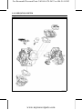
Cylinder Head
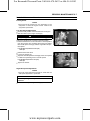
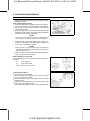
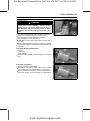
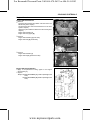
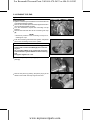
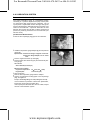
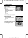
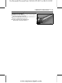
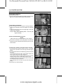
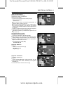
each piston at the T.D.C [A] of the compression
• Set
stroke.
new gaskets and the cylinder head assemblies on
• Put
each cylinder, then let the cylinder heads with push rods
aligned under the rocker arms.
NOTE
○As the head gaskets are coated with sealing agents, be
careful not to damage the surfaces.
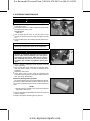
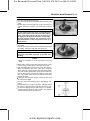
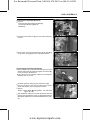
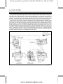
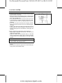
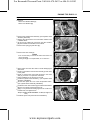
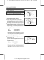
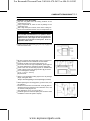
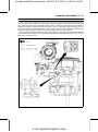
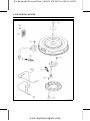
the cylinder head bolts following the tightening
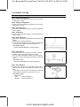
• Tighten
sequence as shown.
○Install the washer to the third tightening bolt.
[A] #1 Cylinder
[B] #2 Cylinder
Torque - Cylinder Head Bolts: 46 N·m (4.7 kgf·m, 34 ft·lb)
CAUTION
A torque wrench must be used to assure proper
torque. Improper tightening of the head bolts may
result in warping of the cylinder head.
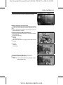
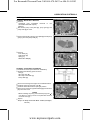
to see that push rod ends are in the hollow of the
• Check
rocker arms.
and adjust the valve clearance.
• Check
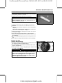
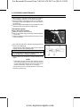
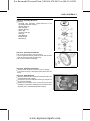
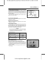
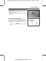
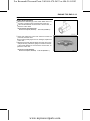
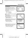
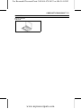
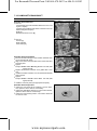
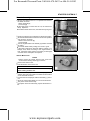
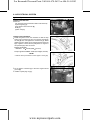
the new gaskets [A] so that the silicone bead side
• Install
[B] face the rocker cover.
• Install the rocker covers.
Torque - Rocker Cover Bolts: 5.9 N·m (0.60 kgf·m, 52 in·lb)
• Install the other removed parts.
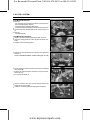
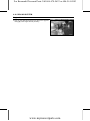
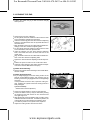
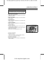
Push Rod Removal
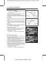
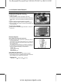
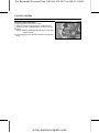
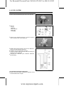
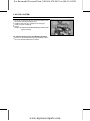
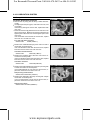
each piston at the T.D.C of the compression stroke.
• Set
the rocker arm (see Valve Mechanism Re• Remove
moval/Installation).
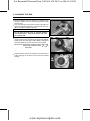
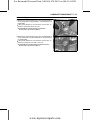
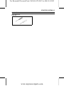
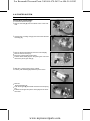
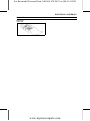
• Pull out the push rods [A]
NOTE
○Mark the push rods to reinstall in their original position
during assembly.
www.mymowerparts.com