1
Service Guide OKIFAX 5700/5900
Chapter 0 Introduction
Front Cover
OKIFAX 5700/5900
FACSIMILE PRODUCTS
Adobe Acrobat printable reference copy
of the OKIDATA Service Training Manual.
10/25/98
Note: This Adobe Acrobat version of the Okidata Service Training Manual was built with the pictures
rendered at 72 dpi, which is ideal for screen viewing. For future updates to this manual, and
more on-line information visit our Business Partner Exchange (BPX) at
http://bpx.okidata.com.
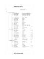
Table of Contents
Page
Service Guide OKIFAX 5700/5900
0 Introduction
Copyright
1 General Information
1.1 General Performance
1.2 General User's Function
1.3 General Maintenance Functions
1.4 General Appearance
....1.4.1 General Appearance of OKIFAX 5700/5900
........Telephone Directory P6
....1.4.2 Control Panel
1.5 Basic Performance Specifications
....Table 1.5.1 (1/8) Basic Performance Specifications
....Table 1.5.1 (2/8) Basic Performance Specifications
....Table 1.5.1 (3/8) Basic Performance Specifications
....Table 1.5.1 (4/8) Basic Performance Specifications
....Table 1.5.1 (5/8) Basic Performance Specifications
....Table 1.5.1 (6/8) Basic Performance Specifications
....Table 1.5.1 (7/8) Basic Performance Specifications
....Table 1.5.1 (8/8) Basic Performance Specifications
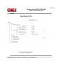
1.6 Reports and Lists
....1.6.1 Reports & List Specifications (1/2)
....1.6.1 Shows Reports and Lists (2/2)
........Active Memory Files P1
........Active Memory Files P2
........Active Memory Files
........Activity Report
........Message Confirmation (Normal Report)
........Memory Confirmation (Error Report)
........Broadcast Entry Report P1
........Broadcast Entry Report P2
........Broadcast Entry Report P1
........Broadcast Entry Report P2
........Broadcast Entry Report (Broadcast TX)
........Broadcast Confirmation Report P1
........Broadcast Confirmation Report P2
........Broadcast Confirmation Report P1
........Broadcast Confirmation Report P2
........Broadcast Confirmation Report (Broadcast TX by Speed
dial)
........Configuration P1
........Configuration P2
........Configuration P3
........Configuration P1
........Configuration P2
........Telephone Directory P1
........Telephone Directory P2
........Telephone Directory P3
........Telephone Directory P4
........Telephone Directory P5
........Telephone Directory P1
2
3
4
5
6
7
8
9
10
11
12
13
14
15
16
17
18
19
20
21
22
23
24
25
26
27
28
29
30
31
32
33
34
35
36
37
38
39
40
41
42
43
44
45
46
47
48
Table of Contents
........Telephone Directory P2
........Telephone Directory P3
........Telephone Directory P4
........Telephone Directory P5
........Telephone Directory P6
........Telephone Directory P7
........Telephone Directory P8
........Telephone Directory (Speed dial)
........Power Outage Report
........Confidential RX Report
........Protocol Dump P1
........Protocol Dump P2
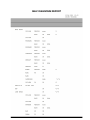
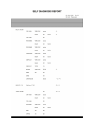
........Self Diagnosis Report
........Function List P1
........Function List P2
........Function List P3
........Function List P1
........Function List P2
........Function List P3
........Group Directory
........Group Directory P1
........Group Directory P2
........Group Directory (Speed dial)
........Protocol Dump P1
........Protocol Dump P2
........NIC Configuration
........Banner Sheet
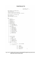
2 Installation
2.1 General Setup Information
2.2 Site Selection
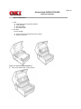
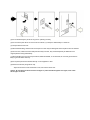
2.3 Unpacking
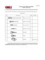
2.4 Check of Contents
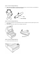
2.5 Installation of Attachments
2.6 AC Cord Connection
2.7 Telephone and Line Connections
2.8 Packing for Shipment
2.9 Initial Settings
....2.9.1 General Procedure of Key Operation
........User Functions
....2.9.2 Technical Functions
........2.9.2.1 Technical Functions Operation 1
........2.9.2.2 Technical Functions Operation 2
........2.9.2.2.1 T1 (TX) Timer Value
........2.9.2.2.2 T1 (RX) Timer Value
........2.9.2.2.3 T2 Timer *100ms
........2.9.2.2.4 Error Criterion
........2.9.2.2.5 Attenuator
........2.9.2.2.6 T/F Tone Att.
........2.9.2.2.7 MF Att.
........2.9.2.2.8 Ring Dura. *10ms
........2.9.2.2.9 CML Timing *100ms
Page
49
50
51
52
53
54
55
56
57
58
59
60
61
62
63
64
65
66
67
68
69
70
71
72
73
74
75
76
77
78
79
80
81
82
83
84
85
86
87
88
89
90
91
92
93
94
95
96
97
98
Table of Contents
........2.9.2.2.10 LED Headstrobe
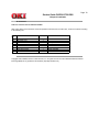
........Service Personnel Initial Settings Table 2.9.2.3 (1/11)
........Service Personnel Initial Settings Table 2.9.2.3 (2/11)
........Service Personnel Initial Settings Table 2.9.2.3 (3/11)
........Service Personnel Initial Settings Table 2.9.2.3 (4/11)
........Service Personnel Initial Settings Table 2.9.2.3 (5/11)
........Service Personnel Initial Settings Table 2.9.2.3 (6/11)
........Service Personnel Initial Settings Table 2.9.2.3 (7/11)
........Service Personnel Initial Settings Table 2.9.2.3 (8/11)
........Service Personnel Initial Settings Table 2.9.2.3 (9/11)
........Service Personnel Initial Settings Table 2.9.2.3 (10/11)
........Service Personnel Initial Settings Table 2.9.2.3 (11/11)
........2.9.2.4 TEL/FAX Automatic Switching
........2.9.2.5 TAD mode
........2.9.2.6 Outline of Parallel Pickup
....2.9.3 User's Functions
....2.9.4 Location Program
........2.9.4.1 Select Menu is shown as below:
........2.9.4.1 Location Program (1/2)
........2.9.4.1 Location Program (2/2)
....2.9.5 Setup
........2.9.5.1 Clock Adjustment
........2.9.5.2 ID/Password Programming
............2.9.5.2.1 TSI/CSI
............2.9.5.2.2 Sender ID
........2.9.5.3 Machine Settings:
............2.9.5.3.1 Auto Answer Mode
............2.9.5.3.2 TX Mode Default
........2.9.5.4 Dial Options
........2.9.5.4 Dial Options Table
............2.9.5.4.1 Redial Tries
............2.9.5.4.2 Redial Interval
............2.9.5.4.3 Dial Prefix
........2.9.5.5 Incoming Options
............Table 2.9.5.5 Incoming Options
............2.9.5.5.1 CNG Count
........2.9.5.6 Report Options:
............2.9.5.5.2 Distinctive Ring
........2.9.5.7 LAN Options:
............2.9.5.7 Table
............2.9.5.7.1 IP Address
............2.9.5.7.2 Subnet Mask
............2.9.5.7.3 Default Gateway
....2.9.6 User Default Setting
....2.9.7 Technical Default Setting
....2.9.8 Default Setting of Dial Parameters
....2.9.9 Off-line tests
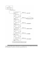
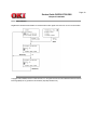
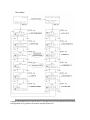
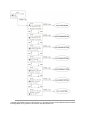
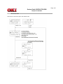
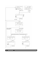
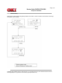
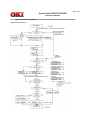
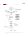
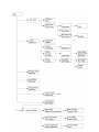
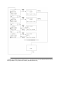
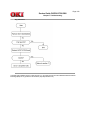
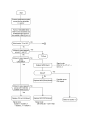
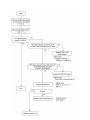
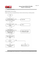
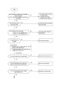
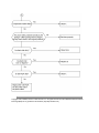
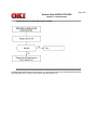
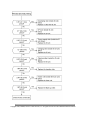
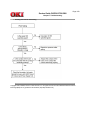
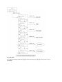
........2.9.9.1 Self Diagnosis Flow
........Self Diagnosis Report
....2.9.10 On-line Tests
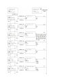
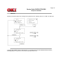
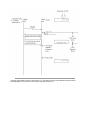
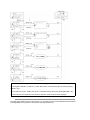
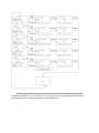
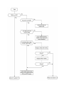
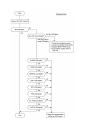
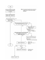
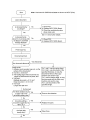
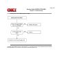
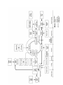
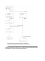
........2.9.10.1 Typical Transmission Flow Diagram
Page
99
100
101
102
103
104
105
106
107
108
109
110
111
112
113
114
115
116
117
118
119
120
121
122
123
124
125
126
127
128
129
130
131
132
133
134
135
136
137
138
139
140
141
142
143
144
145
146
147
148
149
Table of Contents
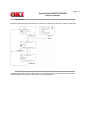
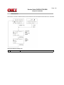
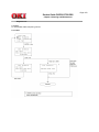
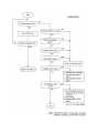
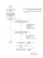
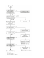
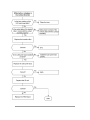
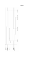
........2.9.10.2 Typical Reception Transmission Diagram
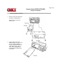
2.10 Installation of optional units
....2.10.1 Optional units
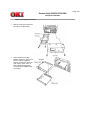
....2.10.2 Memory Board Installation Instruction
....2.10.3 Network Card Installation Instruction
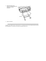
....2.10.4 G4 Board Installation Instruction
3 Brief Technical Description
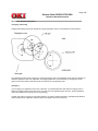
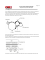
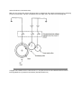
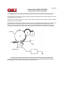
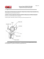
Electrophotographic Process Flow
3.1 Fundamentals of the Electro-Photographic Process
3.2 Actual Electrophotographic Process
3.3 Board and Units
3.4 Overall Dimension and Mechanical Structure
4 Disassembly
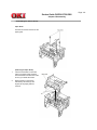
4.0 General
....4.1 Precautions for Parts Replacement
....4.2 Tools
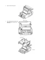
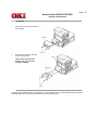
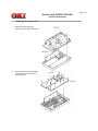
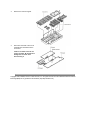
....4.3 How to Disassemble and Reassemble
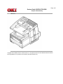
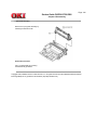
........Whole Unit Picture
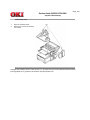
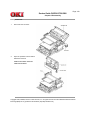
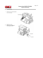
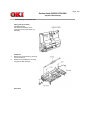
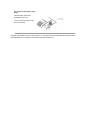
........4.3.1 Document Table Cover
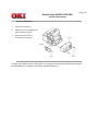
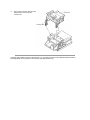
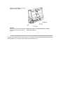
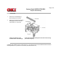
........4.3.2 Rear Cover and NCU Cover
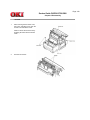
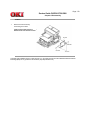
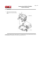
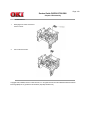
........4.3.3 Main Cover
........4.3.4 Operation Unit
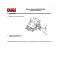
........4.3.5 NCU Board
........4.3.6 MODEM Board
........4.3.7 Plate Package
........4.3.8 Scanner Unit (CIS)
........4.3.9 Stacker Frame
........4.3.10 Printer Unit
........4.3.11 Fan and Fan Guard
........4.3.12 Main Board
........4.3.13 Contact Assembly and High-/Low Voltage Power
Supply Boards
........4.3.14 Disassembling the Operation Unit
............4.3.14.1 Disassembling the Operation Unit
........4.3.15 Disassembling the Scanner Unit (L)
........4.3.16 Scanner (CIS)
........4.3.17 PC1/PC2 Sensors
........4.3.18 Speaker
........4.3.19 Scanner Motor
........4.3.20 Disassembling the Printer Unit
........4.3.21 LED Head
........4.3.22 Toner Lockout Board
........4.3.23 Stacker Cover
........4.3.24 Fusing Unit
........4.3.25 Manual Feed Assembly
........4.3.26 Back-up Roller, Transfer Roller
........4.3.27 Resist Roller, Hopping Roller, Sensor Plates
........4.3.28 Eject Guide Assembly
5 Adjustments
5.1 Setting of LED Print Head Drive Time
....Settings of Technical Function No. 26 (Table 5.1.1)
Page
150
151
152
153
154
155
156
157
158
159
160
161
162
163
164
165
166
167
168
169
170
171
172
173
174
175
176
177
178
179
180
181
182
183
184
185
186
187
188
189
190
191
192
193
194
195
196
Table of Contents
....5.2.1 Confirmation Items
....5.2.2 Measurement
6 Cleaning and Maintenance
6.1 Replacement of Consumables
6.2 Routine Inspection
6.3 Printer Counter Display/Clear (User)
6.4 Printer Counter Display/Clear (Service)
6.5 Self-Diagnosis Test
6.6 Sensor Calibration Test
6.7 LED Test
6.8 Tone Send Test
6.9 High-Speed Modem Send Test
6.10 High-Speed Modem Receive Test
6.11 MF Send Test
6.12 Tone (TEL/FAX)
6.13 Protocol Data Dump Printing
6.14 System Reset
6.15 Service Codes
....Service Code list [Table 6.15.1] (1/2)
....Service Code list [Table 6.15.1] (2/2)
....G4 Service Code Lists
7 Troubleshooting
7.0 Extension cable lists
7.1 Overview
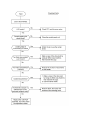
....7.1 Overall Troubleshooting Flow Chart
....7.2 No LCD Operation
....7.3 ALARM LED On
....7.4 Printing Test Failure
....7.5 No Local Copy
....7.6 Auto Dial Failure
....7.7 Transmission Problem
....7.8 Auto Reception Failure
....7.9 Reception Problem
....7.10 Sensor Calibration Test
....7.11 LED Test
....7.12 Tone Send Test
....7.13 High-Speed Modem Test
....7.14 MF Send Test
....7.15 Tone (TEL/FAX) Send Test
....7.16 No Acoustic Line Monitor
....7.17 Power Supply Unit
....7.18 No Document Feeding
....7.19 Multiple Document Feeding
....7.20 Document Skew
....7.21 Document Jam
....7.22 Printer Unit
........7.22.1 Precaution
........7.22.2 Troubleshooting Flow Charts of Printer Unit
........Table 7.22.2 Alarm Display
............Troubleshooting flow chart 1: Top Cover is Open
............Troubleshooting flow chart 2: Replace Image Drum
Message
Page
197
198
199
200
201
202
203
204
205
206
207
208
209
210
211
212
213
214
215
216
217
218
219
220
221
222
223
224
225
226
227
228
229
230
231
232
233
234
235
236
237
238
239
240
241
242
243
244
245
Table of Contents
............Troubleshooting flow chart 3: Engine Controller Error
............Troubleshooting flow chart 4: Fuser Unit Thermal Error
............Troubleshooting flow chart 5: Paper Jams
............Troubleshooting flow chart 6: No Paper Tray or No
Paper
............Action Items (Printer Unit-LCD Message) Table 7.22.2
............Sample Image Problems (Figure 7.22.1)
............Troubleshooting flow chart 7: Light or Blurred Output
............Troubleshooting flow chart 8: Smeared Background on
Output
............Troubleshooting flow chart 9: Blank Output
............Troubleshooting flow chart 10: Vertical Black Stripes on
Output
............Troubleshooting flow chart 11: Evenly Spaced Marks on
Output
............Troubleshooting flow chart 12: Missing Print on Output
............Troubleshooting flow chart 13: Vertical White Stripes on
Output
............Troubleshooting flow chart 14: Poor Fusing
8 Dipswitch Setting Tables
Portuguese
A Board Descriptions
Preface
Service Caution
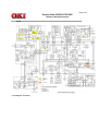
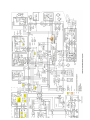
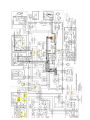
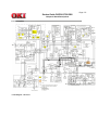
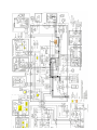
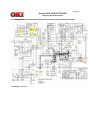
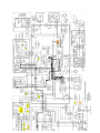
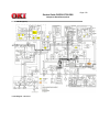
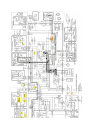
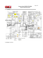
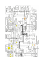
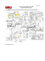
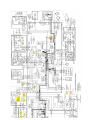
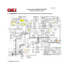
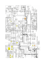
A1.1 Unit Configuration and Block Diagram
....Block Diagram
A2.1 Signal Flow Explanation
....1. Copy
....2. G3 TX (MH/MR/MMR)
....2-1. G3 TX (JBIG): OKIFAX 5900 only
....3. G3 RX (MH/MR/MMR)
....3-1. G3 RX (JBIG): OKIFAX 5900 only
....4. PC Print (Option)
....5. PC Scanner (Option)
....6. PC-FAX TX (Option)
....7. PC-FAX RX (Option)
....8. ISDN PC-FAX G3 TX (Option)
....9. ISDN PC-FAX G3 RX (Option)
....10. ISDN G3 TX (Option)
....11. ISDN G3 RX (Option)
....12. G4 TX (Option)
....13. G4 RX (Option)
....14. LAN Print (Option)
....A3.1 Toner Low Detection
....A3.2 Centronics Parallel Interface
....A3.3 Electrophotographic Process
....A3.4 Process Operation Descriptions
B Print Operation Description
B.1 Mechanical Components
B.2 Description of Print Operations
....1) Hopping and feeding
Page
246
247
248
249
250
251
252
253
254
255
256
257
258
259
260
261
262
263
264
265
266
267
268
269
270
271
272
273
274
275
276
277
278
279
280
281
282
283
284
285
286
287
288
Table of Contents
....2) Charging
....3) Exposure
....4) Developing
....5) Transfer
....6) Fusing
....7) Cleaning
....8) Cleaning of rollers
B.3 Errors
....B.3.1 Errors List
....B.3.2 Major Trouble Errors
........B.3.2.1 Fuse Error
........B.3.2.2 Fan Error
........B.3.2.3 Paper Feed Monitoring
........B.3.2.4 2'nd Tray Communication Error
........B.3.2.5 Cover Open
....B.3.3 Recoverable errors
........B.3.3.1 Toner Low Detection
B.4 Other Special Cases
....B.4.1 Manual Paper Feed
....B.4.2 Cleaning
....B.4.2 Diagram - Description of Print Operations
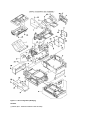
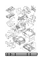
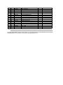
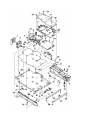
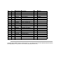
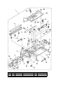
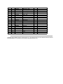
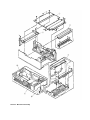
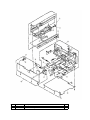
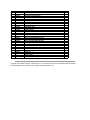
C Illustrated Parts List
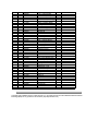
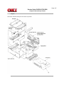
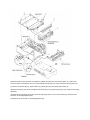
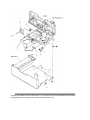
Illustrated Parts List
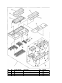
....Section 1: Cabinet Assembly
....Section 2: Control Panel Assy
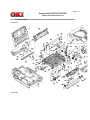
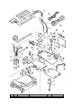
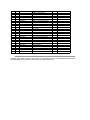
....Section 3: Printer Assembly
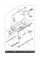
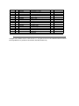
....Section 4: Base Assembly
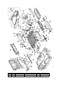
....Section 5: Frame Assy Scanner - (L)
....Section 6: Frame Assy - Scanner (U)
....Section 7: Cables, Option Boards
D Second Paper Feeder
Preface
1. Outline
....1.1 Functions
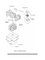
....1.2 External View and Component Names
2. Mechanism Description
....2.1 General Mechanism
....2.2 Hopper Mechanism
3. Parts Replacement
....3.1 Precautions Concerning Parts Replacement
....3.2 Parts Layout
....3.3 Parts Replacement Methods
........3.3.1 Stepping motor (Hopping)
........3.3.2 TQSB2 PCB
........3.3.3 Hopping Roller Shaft Assy and One-way Clutch Gear
4. Troubleshooting
....4.1 Precautions Prior to the Troubleshooting
....4.2 Preparations for the Troubleshooting
....4.3 Troubleshooting Method
........4.3.1 LCD Status Message List
5. Connection Diagram
Page
289
290
291
292
293
294
295
296
297
298
299
300
301
302
303
304
305
306
307
308
309
310
311
312
313
314
315
316
317
318
319
320
321
322
323
324
325
326
327
328
329
330
331
332
333
334
335
336
337
Table of Contents
....5.1 Interconnection Diagram
....5.2 PCB Layout
6 Parts List
E PC-Loading
PC Loading
....1. General
........1.1 Application
........1.2 General
........1.3 Note on Explanation
........1.4 Related Document
....2. Basic Operation
........2.1 Supported Functions
........2.2 Differences from HSLS
........2.3 G4 PC Loading
............2.3.1 Operating Conditions
....3. PC Loading Procedure
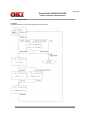
........3.1 PC Loading Upon Memory Error Occurrence
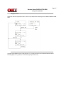
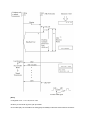
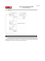
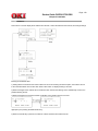
............3.1.1 Explanation on Procedure
............3.1.2 Procedural Sequence Diagram
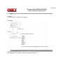
........3.2 PC Loading by Manual Operation
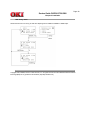
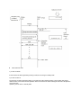
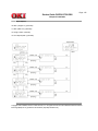
............3.2.1 Explanation of Procedure
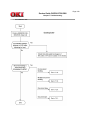
............3.2.2 Procedural Sequence Diagram
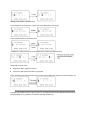
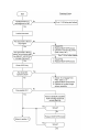
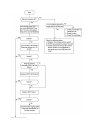
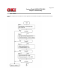
............3.2.3 Operation Flow
........3.3 G4 Board PC Loading Procedure
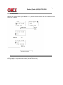
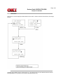
............3.3.1 Explanation of Procedure
............3.3.2 Sequence Diagram
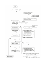
............3.3.3 G4 PC Loading Flow
....4. LCD Messages
....5. Buzzer Sounding Patterns
........5.1 Upon Start of PC Loading
........5.2 Upon Normal End
........5.3 Upon Error Occurrence
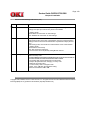
....6. List of Error Causes and Corresponding Codes
....7. Cautions
....8. Loading Processing Time
........8.1 Main Board
........8.2 ISDN Option Board
Page
338
339
340
341
342
343
344
345
346
347
348
349
350
351
352
353
354
355
356
357
358
359
360
361
362
363
364
365
366
367
368
369
370
371
372
373
Service Manual for OF53/56Plus
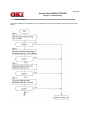
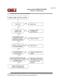
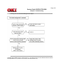
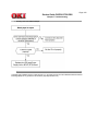
7 Troubleshooting
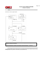
............Overall Troubleshooting Flowchart
374
Page: 2
Service Guide OKIFAX 5700/5900
Chapter 0 Introduction
Copyright
This document may not be reproduced without the written permission of Okidata Training and Publications. Every
effort has been made to ensure the accuracy of the information contained in this training course. Okidata is not
responsible for errors beyond its control.
Copyright / About Information
Copyright 1999 by Okidata All rights reserved.
Written by Okidata Training and Publications
Contact
Please address any comments on this publication to:
Mailing Address Okidata
Training and Publications
2000 Bishops Gate Blvd.
Mount Laurel, NJ 08054-3499
Web Site
www.okidata.com
Copyright Listing
OKIDATA is a registered trademark of Oki Electric Industry Company, Ltd.; marques deposee de Oki Electric
Industry Company, Ltd.; marca registrada, Oki Electric Industry Company, Ltd.
IBM, PC, PC-DOS, and Proprinter XL are registered trademarks of International Business Machines Corporation.
Microsoft and MS-DOS are registered trademarks and Microsoft Basic, Windows, TrueImage, and TrueType are
trademarks of Microsoft Corporation.
Okilink II is a trademark of Oki Electric Industry Company, Ltd.
ZIP Code is a registered trademark of the United States Postal Service.
Copyright 1998, Okidata, Division of OKI America, Inc. All rights reserved. See the OKIDATA Business Partner
Exchange (BPX) for any updates to this material. (http://bpx.okidata.com)
Page: 3
Service Guide OKIFAX 5700/5900
Chapter 1 General Information
1.1 General Performance
1 Type of appearance
l
Desktop type
2 Applicable lines
l
l
l
l
3
4
5
6
7
8
9
10
11
12
PSTN (Public switched telephone network)
PBX (Private branch exchange)
ISDN (Integrated service digital network)
LAN (Local area network)
Note: ISDN and LAN are option.
Compatibility
l ITU-T Group 3 facsimile transceiver
l ITU-T Group 4 facsimile transceiver (option)
Document width
l Max. 216 mm (8.5 inches [North American Letter])
l Min. 148 mm (5.83 inches [ISO A5 size])
Effective reading width
(TX):
l Max. 215.4 mm (NA Letter)
l 208.6 mm (ISO A4 size)
(RX):
l 211.3 mm (NA Letter)
l 211.3 mm (ISO A4 size)*1
* Printing width will be 206 mm
Scanning length
l 128 mm to 356 mm (5.06 inches to 14 inches)
(Length setting: Long document s(1500 mm) are also available.)
Automatic document feeder (ADF)
l 50 sheets (NA Letter/A4-size: 20-lb/75 gm Oki Data recommended paper)
l 30 sheets (North American Letter/A4-size: 16 to 28-1b bond/60-105 gm)
Recording paper or sheet
l 1st cassette: North American Letter/NA Legal/A4-size plain paper cut 250 sheets capacity
(20-lb/75 gm)
l 2nd cassette (option): North American Letter/NA Legal/A4-size plain paper cut 500 sheets
capacity (20-lb/75 gm)
l Manual paper feeder: Transparency for overhead projector, applicable. sheet size: NA
Letter/NA Legal/A4-size
* : Oki Data Recommended paper
Printable width
l North American: 211.3 mm (203.2 mm for assured quality)
l North American Legal: 211.3 mm (203.2 mm for assured quality)
l ISO A4: 206.0 mm (197.3 mm for assured quality)
Printable length
l NA Letter: 273.4 mm (10.76 inches) / 266.7 mm (10.49 inches) for assured quality
l NA Legal: 349.6 mm (13.76 inches) / 342.9 mm (13.49 inches) for assured quality
l ISO A4: 291 mm (11.46 inches) / 284.3 mm (11.19 inches) for assured quality
Copy stacker
l Face down stacking: Max. 200* sheets
l Face up stacking: Max. 10* sheets
*Note 1: Oki Data Recommended paper
*Note 2: Face down or face up stacking is changeable by the lever.
Scanning resolution
a) Horizontal
l 300 dots per inch (Note: 600 dpi x 15.4 mm; copy is available)
b) Vertical
l 300 dots per inch, 15.4, 7.7 and 3.85 lines per mm (Note: 300 dpi x 300 dpi; Transmission
is available.
13 Scanning method
l 2592 bits contact image sensor
14 Recording resolution)
a) Horizontal: 600 dots/inch
b) Vertical:
Variable:
l
l
l
l
STD mode (A4: 3.85 to 5.06 line/mm) (Letter: 3.85 to 5.28)
FINE mode (A4: 7.7 to 9.3 line/mm) (Letter: 7.7 to 10.57)
EX-FINE mode : (A4: 15.4 line/mm) (A4 15.4 to 19.87 line/mm) (Letter: 15.4 to 21.15)
EX-FINE (300 dot/inch): (A4: 300 to 387 mm/line) (Letter: 300 to 412)
Fixed:
l
l
l
l
l
EX-FINE mode : 300 dot/inch, 15.4 line/mm
FINE mode: 7.7 line/mm
STD mode: 3.85 line/mm
PC-Print: 600 dot/inch, 300 dot/inch
15 Printing method
16
17
18
19
20
21
22
23
24
25
Electrophotographic printing
l 211.3 mm (2496 bits) LED printhead
Minimum scan line time for reception
l When receiving from OKIFAX or ECM: 0 ms
l When receiving from non- OKIFAX and non ECM: 10 ms at 3.85 line/mm; 5 ms at 7.7
line/mm, 15.4 line/mm
Print speed
l Max. 10 sheets per minute (at NA letter size)
Coding scheme
l Modified Huffman (MH)
l Modified READ (MR)
l Modified Modified READ (MMR)
l JBIG (only for OKIFAX 5900)
Modem (Rev. 2)
l ITU-T Rec. V.29: 9600 bps for use on point-to-point 4-wire leased telephone type circuits.
l ITU-T Rec. V.27 ter: 4800 bps modem for use in GSTN (General Switched Telephone
Network)
l ITU-T Rec. V.21 channel 2: 300 bps duplex modem for GSTN
l ITU-T Rec. V.17: 2-wire modem for fax applications up to 14.4 kbps
l ITU-T Rec. V.34
Transmission speed
l 2.5 sec. per sheet of ITU-T No. 1 evaluation test chart (for OKIFAX 5900)
l 3.0 sec. per sheet of ITU-T No. 1 evaluation test chart (for OKIFAX 5700)
Note: This is Phase C time at 3.85 line/mm.
Protocol
l ITU-T Rec. T.30
l ITU-T Rec. G4 Class 1 (option)
l OKI special protocols: High-speed protocol (G3)
Error correction mode (ECM)
l ITU-T ECM
Image memory
l Basic mode: 2.5 M-byte (OKIFAX 5700) & 4.5 M-byte (OKIFAX 5900)
l Optional memory: 2.0/4.0 M-byte
Liquid crystal display (LCD)
l Four lines of 20 characters for operation guidance, check and various kinds of information
Power source
l
l
Nominal input voltage 120 VAC for ODA version
Nominal input voltage 230 VAC for INT'L version
26 MFP (Multi- Function Peripheral) function
l PC Printer Function
l PC Scanner Function
l PC Fax Modem Function
Note: For details, see "Product Specification for MFP". Hardware is standard and software is
Bi-Centro interface.
27 ISDN function (option)
l G4 function
l ISDN G4: Communication
l ISDN G3: Communication
l ISDN: Report and List
28 Network print service
l
l
l
l
Netware
TCP/IP
Windows NT/95/3.1
T600 dpi, 10 ppm
Note: For details, see "Product Specification for Network Print Service"
NA = North America
Copyright 1998, Okidata, Division of OKI America, Inc. All rights reserved. See the OKIDATA Business Partner
Exchange (BPX) for any updates to this material. (http://bpx.okidata.com)
Page: 4
Service Guide OKIFAX 5700/5900
Chapter 1 General Information
1.2 General User's Function
1) Transmission
1 Transmit mode
l
l
2
3
4
5
6
7
8
9
10
11
12
13
14
Automatic transmit mode
Manual transmit mode
Instant Dialing
Delayed feeder transmission
Memory transmission
l 40 sessions
Delayed memory transmission (within 3 days)
l 20 specified times for OKIFAX 5700
l 30 specified times for OKIFAX 5900
Sequential broadcast (Memory)
l 150 stations for OKIFAX 5700
l 240 stations for OKIFAX 5900
Delayed broadcast
l 20 specified times for OKIFAX 5700
l 30 specified times for OKIFAX 5900
Confidential message transmission
l Feeder Confidential TX
l Memory Confidential TX
Relay broadcast initiate
l Feeder Relay broadcast initiate
l Memory Relay broadcast initiate
Polling transmission
l Feeder Polling TX
l Memory Polling TX
Bulletin Poll transmission (When Box number is opened).
l 16 boxes
Batch transmission
Priority transmission
Transmission preparation (Feeder)
2) Reception
1 Receive mode
l
l
l
l
l
l
2
3
4
5
6
7
Automatic receive mode
Manual receive mode
TEL/FAX receive mode
TAD mode
Memory receive mode
Forwarding mode
Memory only reception
No toner/No paper reception (memory)
Confidential message reception
l 16 mail boxes
Fax forwarding for incoming calls
Fax forwarding for no toner/no paper reception
Polling reception
3) Convenience
1 Dual access
2 Automatic redial
3 Last number redial (Manual redial)
4 Local copy of a document, including multiple copies
l
99 copies max.
5 Sender identification (Sender ID)
6 Personal identification (Personal ID)
7 TSI/CSI: Local telephone number
8 Acoustic monitor (only TX mode)
l
5 level selectable
9 Automatic alternate selecting call
(FAX No. + FAX No. can be registered in one-touch keys).
l OKIFAX 5700: Speed Dial (1 to 40) are assigned to one-touch keys.
l OKIFAX 5900: Speed Dial (1 to 80) are assigned to one-touch keys.
10 Half-tone transmission (at FINE resolution)
l
64 scale gradations
11 Page re-transmission (Only when memory TX mode)
12 Distinguishing text from pictures
13 Vertical reduction printing (Reduction rate is from 100% to xx%).
Note: xx is Letter 72.8%, A4 77.5%
14 Smoothing printing
In case of 8 dot/mm x 3.85 lines/mm --> 300 dot/inch x 784 lines/inch
15 Auto dialing
16
17
18
19
20
21
22
23
24
25
26
27
28
29
30
31
32
l Speed dialing:
OKIFAX 5700: 1 to 140 (1 to 40 are assigned to one-touch keys)
OKIFAX 5900: 1 to 230 (1 to 80 are assigned to one-touch keys)
l Group dialing: 20 groups
l Keypad dialing
l Chain dialing
l Mixed dialing
Real-time dialing
Dialing with off hook condition or when the HOOK key is pressed.
Automatic pause signal insertion
Local copy
Telephone directory (Alpha/Location) dialing
TEL/FAX automatic switching
TAD mode (for external telephone answering device)
Session number
Closed user group (Direct mail rejection)
Contrast and resolution control
Key touch tone
Printer counter display (For drum, toner, print, and scan)
Quick scanning
Time and date setting
Language selection
l 2 languages (LCD and Report)
Distinctive ring detect
Restricted access
Beep sound
4) Reports
1
2
3
4
5
6
7
8
9
10
11
12
Function list
Configuration
Phone directory
Group directory
Activity report
Active memory files
Broadcast
Protocol dump (G3 and G4)
NIC configuration
Log. report
G4 Log. report
Self diagnosis report
5) Report options
1
2
3
4
MCF. (Single-Loc.)
MCF. (Multi-Loc.)
Image in MCF.
Error report (MCF).
Copyright 1998, Okidata, Division of OKI America, Inc. All rights reserved. See the OKIDATA Business Partner
Exchange (BPX) for any updates to this material. (http://bpx.okidata.com)
Page: 5
Service Guide OKIFAX 5700/5900
Chapter 1 General Information
1.3 General Maintenance Functions
1) Local tests
1 Self-diagnosis
Main board
l
l
l
l
l
l
CPU ROM/RAM check
Flash memory check (Program, Language, and Default)
Modem
RAM check
Toner cartridge
Option memory check
DEVICE ID
l
LAN Board check (option)
ISDN board (option)
2
3
4
5
6
7
8
9
10
11
12
13
14
15
16
17
l CPU ROM/RAM check
Sensor calibration (Adjustment of scanning level)
LED test
Tone send test (When NCU board is installed)
High-speed modem send test (When NCU board is installed)
High-speed modem receive test (When NCU board is installed)
MF tone test (When NCU board is installed)
Tone (TEL/FAX) test (When NCU board is installed)
Loop back 1 (When ISDN option board is installed)
Loop back 2 (When ISDN option board is installed)
INFO0 sending (When ISDN option board is installed)
INFO1 sending (When ISDN option board is installed)
INFO2 sending (When ISDN option board is installed)
INFO3 sending (When ISDN option board is installed)
Pulse (1kHz) send (When ISDN option board is installed)
Pulse (2kHz) send (When ISDN option board is installed)
Pulse (N2kHz) send (When ISDN option board is installed)
2) Technical setup
3) System reset
l
l
l
All data clear
Location data clear
Configuration data clear
4) Default type set
5) PC loading
6) G4 PC loading
Copyright 1998, Okidata, Division of OKI America, Inc. All rights reserved. See the OKIDATA Business Partner
Exchange (BPX) for any updates to this material. (http://bpx.okidata.com)
Page: 6
Service Guide OKIFAX 5700/5900
Chapter 1 General Information
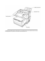
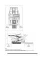
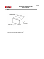
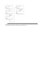
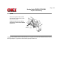
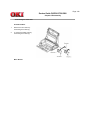
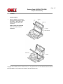
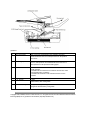
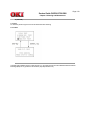
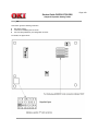
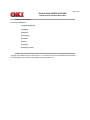
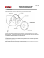
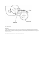
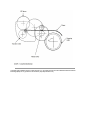
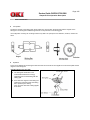
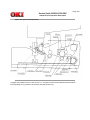
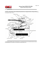
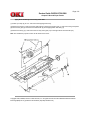
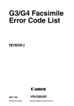
1.4 General Appearance
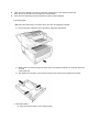
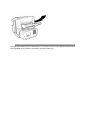
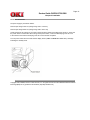
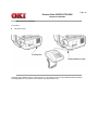
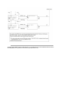
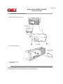
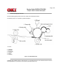
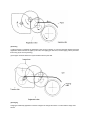
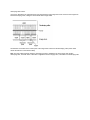
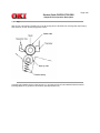
Figure 1.4.1 shows the general appearance of the OKIFAX 5700/5900.
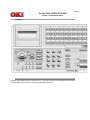
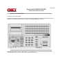
Figure 1.4.2 Control Panel for OKIFAX 5700/5900.
Copyright 1998, Okidata, Division of OKI America, Inc. All rights reserved. See the OKIDATA Business Partner
Exchange (BPX) for any updates to this material. (http://bpx.okidata.com)
Page: 7
Service Guide OKIFAX 5700/5900
Chapter 1 General Information
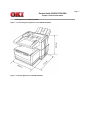
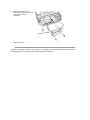
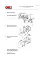
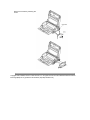
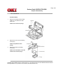
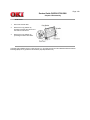
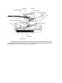
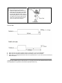
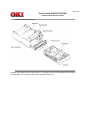
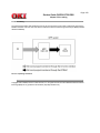
1.4.1 General Appearance of OKIFAX 5700/5900
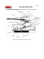
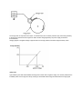
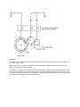
Figure 1.4.1 shows the general appearance of the OKIFAX 5700/5900.
Figure 1.4.1 General Appearance of OKIFAX 5700/5900.
Copyright 1998, Okidata, Division of OKI America, Inc. All rights reserved. See the OKIDATA Business Partner
Exchange (BPX) for any updates to this material. (http://bpx.okidata.com)
Page: 8
Service Guide OKIFAX 5700/5900
Chapter 1 General Information
Telephone Directory P6
Copyright 1998, Okidata, Division of OKI America, Inc. All rights reserved. See the OKIDATA Business Partner
Exchange (BPX) for any updates to this material. (http://bpx.okidata.com)
Page: 9
Service Guide OKIFAX 5700/5900
Chapter 1 General Information
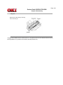
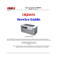
1.4.2 Control Panel
Copyright 1998, Okidata, Division of OKI America, Inc. All rights reserved. See the OKIDATA Business Partner
Exchange (BPX) for any updates to this material. (http://bpx.okidata.com)
Page: 10
Service Guide OKIFAX 5700/5900
Chapter 1 General Information
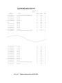
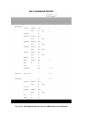
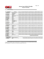
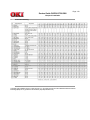
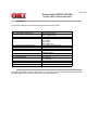
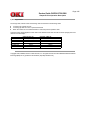
1.5 Basic Performance Specifications
Table 1.5.1 (1/8) Basic Performance Specifications
Table 1.5.1 (2/8) Basic Performance Specifications
Table 1.5.1 (3/8) Basic Performance Specifications
Table 1.5.1 (4/8) Basic Performance Specifications
Table 1.5.1 (5/8) Basic Performance Specifications
Table 1.5.1 (6/8) Basic Performance Specifications
Table 1.5.1 (7/8) Basic Performance Specifications
Table 1.5.1 (8/8) Basic Performance Specifications
Copyright 1998, Okidata, Division of OKI America, Inc. All rights reserved. See the OKIDATA Business Partner
Exchange (BPX) for any updates to this material. (http://bpx.okidata.com)
Page: 11
Service Guide OKIFAX 5700/5900
Chapter 1 General Information
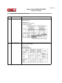
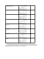
Table 1.5.1 (1/8) Basic Performance Specifications
No.
1
Item
Specifications
Applicable line
1) PSTN (Public switched telephone network)
2) PBX (Private branch exchange)
3) ISDN (Integrated services digital network): Option
4) LAN (Local area network): Option
2
Line interface
1) Impedance
3
600 Ohms balanced
Note: Impedance may differ by the requirement of PTT.
2) Sending power level
0 dBm to -15 dBm range
(Adjustable in 1 dB steps. Technical Setup No. 21)
3) Receiving power level
0 dBm to -40 dBm
(In case of V.34 TX/RX, -3 to -43 dBm
Type of document to be
transmitted
1) Width
2) Length
Max. 216 mm (NA Letter)
Min: 148 mm (ISO A5 size)
Note: Effective reading width is NA Letter 215 mm)
Min. 128 mm
Max. 356 mm (14 inches)
Long document detection: 380 mm, or 150 mm
* Technical Setup No. 10 (To enable or disable the long document
scanning)
3) Thickness
Based on common bond paper
a) 0.08 to 0.13 mm for multiple page feeding
b) 0.06 to 0.15 mm for single page feeding
4) Shape
Rectangular
5) Opacity
Documents allowing less than 40% of the scanner source light to
pass through them.
Copyright 1998, Okidata, Division of OKI America, Inc. All rights reserved. See the OKIDATA Business Partner
Exchange (BPX) for any updates to this material. (http://bpx.okidata.com)
Page: 12
Service Guide OKIFAX 5700/5900
Chapter 1 General Information
Table 1.5.1 (2/8) Basic Performance Specifications
No.
4
Item
Specifications
Effective reading width
Document width
Communication
Mode/Paper width
Effective reading width
Copy size
ISO A4 (210 mm)
[INTL]
G3/A4
208.6 mm for TX
211.3 mm for local copy
A4
NA letter (216 mm)
[US/CANADA]
G3/A4
215.4 mm for TX
211.3 mm for local copy
Letter
Note (*1): Printing width will be 206 mm.
No.
5
Item
Specifications
Automatic document feeder
(ADF)
Max. 50 documents: 20 lb./75gm NA Letter or A4 size paper.
Max. 30 documents: 16 to 28/60 to 105gm; NA or A4 size paper
Documents shall be placed face down on ADF stacker.
6
Document skew
Max. 1.0 mm skew over any advance of 100 mm.
The occurrence of skew exceeding 1 mm per 100 shall be 0.5% or
less.
7
Document jam detection
1) Transmission will stop and line disconnection will occur when the
end of a document is not detected within 380 mm after scanning
begins (except for the long document scanning. Technical Setup No.
10)
2) A jam will also be declared if the document does not reach the
scanning position within 5 seconds after the start of a document feed.
Note: When a jam is detected during message transmission from the
feeder, the machine will stop scanning and disconnect the line, but its
receiving capability will remain valid.
8
Document jam removal
Manual release
Copyright 1998, Okidata, Division of OKI America, Inc. All rights reserved. See the OKIDATA Business Partner
Exchange (BPX) for any updates to this material. (http://bpx.okidata.com)
Page: 13
Service Guide OKIFAX 5700/5900
Chapter 1 General Information
Table 1.5.1 (3/8) Basic Performance Specifications
No.
9
Item
Specifications
Document stacking
Documents up to 297 mm in length, which meet the basic
weight and thickness specification, will exit on the stacker,
and documents of Letter or A4-size will stack in sequence.
The first sheet will be fed first in the feeder and will exit on
the stacker with printing side down.
10
Recording paper or sheet
For the first or second recording paper cassette:
1) Type: Plain paper cut (Bond paper: Xerox 4200 type or equivalent)
2) Size: ISO A4 210 mm x 297 mm
NA Letter 215.9 mm x 279.4 mm / 8.5 inch x 11 inch
NA Legal 14: 215.9 mm x 355.6 mm / 8.5 inch x 13 inch
3) Weight: 16 lbs to 24 lbs/60 to 105 gm base weight
Base weight is defined as the weight of 500 sheets
of 431.8 mm (17 inch) by 558.8 mm (22 inch) or 1 sheet size 1000
mm by 1000 mm.
4) Thickness: 0.08 mm to 0.13 mm
5) Condition: New paper
For the manual loading feeder
1) Type: Plain paper, colored paper, printed paper, envelope
2) Size: LA Letter/A4/NA Legal/Executive/A5/A6/etc.
3) Weight, thickness and condition: Same as above
Note: One single sheet should be loaded on the manual paper
feeder for one occasion.
For best results use Oki Data recommended papers
1) Xerox 4200 (20 - lb/75 gm base weight paper)
2) L-type paper for photo-printers
11
Recording paper cassette
first cassette
Up to 250 sheets/cassette
(Oki Data recommended paper)
second cassette
Up to 500 sheets/cassette
(Oki Data recommended paper)
Copyright 1998, Okidata, Division of OKI America, Inc. All rights reserved. See the OKIDATA Business Partner
Exchange (BPX) for any updates to this material. (http://bpx.okidata.com)
Page: 14
Service Guide OKIFAX 5700/5900
Chapter 1 General Information
Table 1.5.1 (4/8) Basic Performance Specifications
No.
12
Item
Specifications
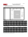
Effective recording area
1) Printable area
Letter Size
inch
mm
PL
PW
EL
EW
T
B
L
R
11
8.5
10.76
8.32
.12
.12
.09
.09
279.4
216
273.4
211.3
3
3
.08
.08
A4 Size
inch
mm
11.7
8.27
11.46
8.11
0.12
0.12
0.08
0.08
297
210
291
206
3
3
2
2
14 inch Legal Size
inch
mm
14
8.5
13.76
8.32
0.12
0.12
0.09
0.09
355.6
216
349.6
211.3
3
3
2.3
2.3
13 inch Legal Size
inch
mm
13
8.5
12.76
8.32
0.12
0.12
0.09
0.09
330.2
216
324.2
211.3
3
3
2.3
2.3
1) Guaranteed printing area
PL
PW
EL
EW
T
B
L
R
Letter Size
inch
mm
inch
mm
11
8.5
10.5
8.0
0.25
0.25
0.25
0.25
11.7
8.27
11.2
7.77
0.25
0.25
0.25
0.25
297
210
284.3
197.3
6.35
6.35
6.35
6.35
279.4
216
266.7
203.2
6.35
6.35
6.35
6.35
A4 Size
14 inch Legal Size
inch
mm
13 inch Legal Size
inch
mm
14
8.5
13.5
8.0
0.25
0.25
0.25
0.25
13
8.5
12.5
8.0
0.25
0.25
0.25
0.25
355.6
216
342.9
203.2
6.35
6.35
6.35
6.35
Note: The printable area means the area allowing actual printing at the time of receiving. The guaranteed printing
area means the area where the printing quality is guaranteed.
330.2
216
317.5
203.2
6.35
6.35
6.35
6.35
These tables do not include vertical and horizontal addressing error (+/- 3 mm) of recording paper.
Copyright 1998, Okidata, Division of OKI America, Inc. All rights reserved. See the OKIDATA Business Partner
Exchange (BPX) for any updates to this material. (http://bpx.okidata.com)
Page: 15
Service Guide OKIFAX 5700/5900
Chapter 1 General Information
Table 1.5.1 (5/8) Basic Performance Specifications
No.
13
Item
Specifications
Copy stacking
The printed copies will be discharged on the stacker with printed face
up or face down.
1) Face down stacking: Up to 200 copies
2) Face up stacking: Up to 10 copies
Note:
1) Using the recommended paper, New standard 20-lb. (Xerox 4200)
2) Except 16 lb. papers.
3) Face down or face up stacking is changeable by the lever.
14
Scanning resolution
Horizontal:
l 300 dot/inch
Vertical:
Transmission mode:
l 300 dot/inch, 15.4 lines/mm (EX-FINE), 7.7 lines/mm (FINE) or
3.85 lines/mm (STD)
15
Image scanning method
NA Letter size (2592-bit) direct contact image sensor
16
Contrast control
The Light and Dark contrasts (low contrast) will be automatically
enhanced to improve image quality.
Slice level shifting has 3 levels of switch selection on operation panel.
17
Recording solution
Horizontal:
l 300 dot/inch
Vertical:
l 300 dot/inch (EX-FINE), 15.4 line/mm (EX-FINE), 7.7 line/mm
(FINE), or 3.85 line/mm (STD)
STD
Fine
Ex-Fine (15.4 line/mm)
Ex-Fine (300 dot/inch)
A4
Letter
3.85 ~ 4.96
7.7 ~ 9.93
15.4 ~ 19.87
300 ~ 387
3.85 ~ 5.28
7.7 ~ 10.57
15.4 ~ 21.15
300 ~ 412
No.
Item
Specifications
18
Copy resolution
19
Recording method
Electro-photographic printing
1) 211.3mm (4992 bits)
20
Recording paper skewing
Maximum allowable skew is + or - 1 mm over an advance of 100 mm.
l
l
l
STD: 200 dot/inch x 3.85 line/mm
FINE/PHOTO: 300 dot/inch x 300 dot/inch
EX-FINE: 600 dot/inch x 15.4 line/mm
21
Copy darkness
1) Black image: Greater than 1.2 OD *
2) White background: Not greater than 0.2 OD
Note: OD: (Optical density)
22
Copy uniformity
Printed copies will exhibit a uniform density of the printed and
background area:
1) From edge to edge: 25%
2) From copy to the next copy: 30%
23
Recording paper running out The fax can detect the no-paper condition by a photosensor.
When the paper has run out in the local copy operation, the scanning
will stop with "PAPER OUT/JAM" on the LCD and an ALARM LED
turns on without an alarm tone.
When the paper has run out while a message is being received and
the no-paper reception is activated, the LCD display will show "MSG.
IN MEMORY", and the ALARM LED turns on.
Copyright 1998, Okidata, Division of OKI America, Inc. All rights reserved. See the OKIDATA Business Partner
Exchange (BPX) for any updates to this material. (http://bpx.okidata.com)
Page: 16
Service Guide OKIFAX 5700/5900
Chapter 1 General Information
Table 1.5.1 (6/8) Basic Performance Specifications
No.
24
Item
Specifications
Minimum scan line time for
receiving
0 ms, when receiving in ECM mode or from an Oki Data facsimile.
5 ms at 15.4 line/mm or 7.7 line/mm and 10 ms at 3.85 line/mm when
receiving from a non-Oki Data facsimile or non-ECM mode.
25
Coding scheme
1) One-dimensional coding scheme:
Modified Huffman (MH)
2) Two-dimensional coding scheme:
Modified READ (MR)
Modified modified READ (MMR)
3) JBIG (only for OKIFAX 5900)
26
Modem operations
1) High-speed Modem
2) Low-speed Modem
3) JBIG
l
l
l
l
l
ITU-T Rec. V.29 (9600/7200 bps)
ITU-T Rec. V.27 ter (4800/2400 bps)
ITU-T Rec. V.17 (14400/12000/9600/7200 bps)
ITU-T Rec. V.33 (14400/12000 bps)
ITU-T Rec. V.34 (33600/28800 bps)
l
ITU-T Rec. V.21 channel 2 (300 bps)
Performs JBIG communication conforming to T.82/T.85 or ITU-T Rec.
Note: Only for OKIFAX 5900, and JBIG is not performed in G4
communication.
27
4) ISDN G4:
ITU-T Rec. T.563, T.521, T.503, T.62, T.6, T.70
Fallback
Automatic fallback will occur according to the following sequence by
FTT, RTN or PPR.
Fallback rank
Transmission
speed
Activated by FTT
(Times)
Activated by RTN
(Times)
Protocol
1st
2nd
3rd
4th
5th
6th
14400 bps
12000 bps
9600 bps
7200 bps
4800 bps
2400 bps
1
1
1
1
2
2
1
1
1
1
1
1
ITU-T V.17 (V.17)
ITU-T V.17 (V.17)
ITU-T V.17 (V.29)
ITU-T V.17 (V.29)
ITU-T V.17 V.27 ter.
ITU-T V.17 V.27 ter.
When the last trial fails, the transmitting station sends out a DCN signal to the remote station for disconnection.
Note:
l
l
No.
Modem automatically performs the fall-back depending upon the line condition.
V.34 fallback sequence: The modem automatically selects transmission speed according to the line condition.
Item
Specifications
28
Protocol
1) ITU-T Rec. T.30
2) Oki Data special protocol (speed protocol)
The T.30 handshaking procedure will be conducted at message
transmission speed instead of 300 baud, during transmission
multi-page.
Note: In High-speed protocol, V.34 is not applied.
3) ITU-T G4 Class 1 (option)
Copyright 1998, Okidata, Division of OKI America, Inc. All rights reserved. See the OKIDATA Business Partner
Exchange (BPX) for any updates to this material. (http://bpx.okidata.com)
Page: 17
Service Guide OKIFAX 5700/5900
Chapter 1 General Information
Table 1.5.1 (7/8) Basic Performance Specifications
No.
29
Item
Specifications
Transmission time
2.5 seconds at 33.6 kbps with JBIG for OKIFAX 5900 and 3.0
seconds at 33.6 kbps for OKIFAX 5700 per sheet of ITU-T No. 1
evaluation test chart.
Note: This speed denotes the time interval corresponding to Phase C
(message transmission phase) as referred to in ITU-T T.30.
Procedure Time
G3
Basic
Image Time
OKIFAX 5700
OKIFAX 5700
OKIFAX 5900
OKIFAX 5900
Initial
Intermediate
Final
33600
8.5 sec. (V34)
1.0 sec. (V34)
1.0 sec. (V34)
Standard 3.0 sec.
Fine 4.2 sec.
Initial
Intermediate
Final
33600
8.5 sec. (V34)
1.0 sec. (V34)
1.0 sec. (V34)
Standard 2.5 sec.
Fine 3.5 sec.
Note: The following table shows the values under the following conditions:
l
l
l
l
Sender ID: OFF
High-speed protocol: OFF
Transmission mode: Memory
Resolution: STD
No.
30
Item
Specifications
Error correction
ITU-T ECM defined in T4, T.30 are provided.
31
Communication mode
Half-duplex
32
Ringing signal detection
sensitivity
1) Voltage range
33
25 to 150 V r.m.s.
Inoperative below 10 V
Note: This range may differ by the requirement of PTT.
2) Frequency range
20 to 68 Hz
Note: This range may differ by the requirement of PTT.
3) Ring response time
One-ringing signal or 5 sec, 10 sec, 15 sec, and 20 sec selectable
Memory capacity (Image
memory)
OKIFAX 5700
OKIFAX 5900
basic model
optional memory
2.5 M-byte
4.5 M-byte
2/4 M-byte
2/4 M-byte
Note 1: ITU-T No. 1 sample document is used to count the number of sheets.
Note 2: Memory back-up time is 72 hours (typical and Battery full charge condition) after the power off condition.
No.
34
Item
Specifications
Telephone handset (option)
General telephone function is available while the power is on.
Note: In the fax special versions, general telephone is available even
when the power is off.
35
Overheat protection
The heater of the fuser unit is controlled within the predetermined
temperature range by the thermistor. If the temperature of the heater
exceeds the range, the LCD displays "PRINTER ALARM 4".
Furthermore, the built-in thermostat in the fuser unit prevents the
heater from being overheated even in the event of the failures in the
above temperature control circuit.
Copyright 1998, Okidata, Division of OKI America, Inc. All rights reserved. See the OKIDATA Business Partner
Exchange (BPX) for any updates to this material. (http://bpx.okidata.com)
Page: 18
Service Guide OKIFAX 5700/5900
Chapter 1 General Information
Table 1.5.1 (8/8) Basic Performance Specifications
No.
36
Item
Specifications
PC interface applications
(Option)
The following four modes are supported:
1) PC Printer function
2) PC Scanner function
3) PC FaxModem function
Note 1: Hardware is standard and software is option for Bi-Centro
interface.
37
Network print service
(option)
38
ISDN G4 (option)
39
Power supply unit and Power Power consumption of the machine
consumption of the machine
l
This function can be used for OKIFAX 5700/5900 network
printer service. The OkiHSP NIC (Network Interface Card)
Ethernet Adapter used for OKIFAX 5700/5900 is originally
designed for the OkiPage printers and is intended to be forward
compatible with
(future) products utilizing an OkiHSP compatible interface.
l Installing the NIC card for OKIFAX 5700/5900 provides
Network print service as an option.
The following four modes are supported.
1) G4 function
2) ISDN G4 communication
3) ISDN G3 communication
4) ISDN Report and List
Mode
Typical power
Transmit
Receive
Local copy
Standby (Power Save OFF)
Standby (Power Save ON)
40
Ambient condition
17W
425W
428W
5.4W
*
Note: ( ): when power save mode is set to ON. Chart: ITU-T No. 1
see table below.
In operation
Power off mode
During Storage
Unit
Temperature
50 - 90
(10-32)
32 - 110
(0-43)
14-110
(-10 - 43)
o
Humidity
20 - 80
10-90
10-90
% RH
Maximum wet bulb
temperature
77
(25)
80.4
(26.8)
----
o
F
o
( C)
F
o
( C)
Minimum difference
35.6
between wet and dry bulb (2)
temperatures
35.6
(2)
----
o
F
o
( C)
1. Storage conditions specified above apply to the machine in packed condition.
2. Temperature and humidity must be in the range where no condensation occurs.
No.
41
Item
Specifications
Dimension (Main body)
1) Width: Approx. 360 mm
2) Depth: Approx. 472 mm
3) Height: Approx. 352
42
Weight (Main body)
Approx. 14 kg
Excluding recording paper and packing materials.
43
Attachment (to the main
board)
OKIFAX 5700/5900 1) AC power cord x 1
2) I/D unit x 1 (Already installed)
3) Toner cartridge x 1
4) Telephone line cord x 1
5) Document stacker x 1
6) One touch sheet x 1 (Already installed)
7) User's guide x 1
Copyright 1998, Okidata, Division of OKI America, Inc. All rights reserved. See the OKIDATA Business Partner
Exchange (BPX) for any updates to this material. (http://bpx.okidata.com)
Page: 19
Service Guide OKIFAX 5700/5900
Chapter 1 General Information
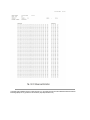
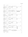
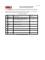
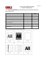
1.6 Reports and Lists
Table 1.6.1 (1/2) Reports and Lists Specifications
Table 1.6.1 (2/2) shows Reports and Lists Specifications
Copyright 1998, Okidata, Division of OKI America, Inc. All rights reserved. See the OKIDATA Business Partner
Exchange (BPX) for any updates to this material. (http://bpx.okidata.com)
Page: 20
Service Guide OKIFAX 5700/5900
Chapter 1 General Information
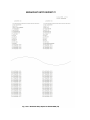
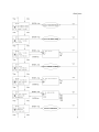
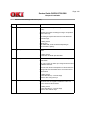
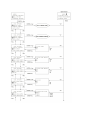
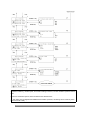
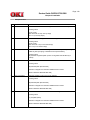
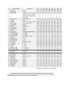
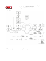
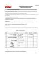
1.6.1 Reports & List Specifications (1/2)
Note: F +OT: Press FUNCTION and One-touch key
FP: Function program setting
TF: Technical function setting
No.
1
Item
Specifications
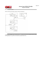
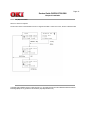
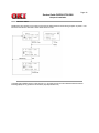
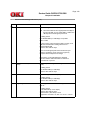
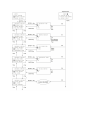
Active memory files
This report will be manually or automatically printed out
for information of transmission/reception data stored in
the memory. When there is no stored image data in the
memory at all, the Active memory files is not printed out.
(MENU key --> Report Print)
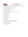
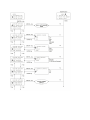
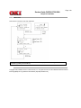
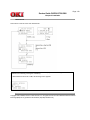
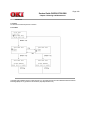
See Fig. 1-6-1-1, Fig. 1-6-1-2, and Fig. 1-6-1-3
2
Activity report
The fax can print out an activity report manually, and
provides of fax machine's last 30 communications. The
report does not contain the results of messages which
were received without errors. However, it does contain
messages received in memory with or without errors.
(MENU key --> Report Print)
See Fig. 1-6-2
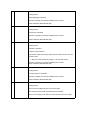
3
Message confirmation report
This report will be manually or automatically printed out
after completion of memory transmission.
1) Manual print
By pressing the ENTER key after a communication.
2) Automatic printout
When the Report Options (to enable or disable automatic
printing after a communication) is set to Enable.
l Single location: (MENU key --> SETUP --> Report
Options: No. 70
l Multi location: (MENU key --> SETUP --> Report
Options: No. 71
See Fig. 1-6-3-1 and Fig. 1-6-3-2
4
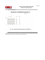
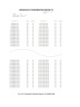
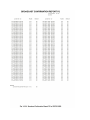
Broadcast entry report
This report will be manually printed out if specified during
operating sequence of a broadcast.
See Fig. 1-6-4-1, Fig. 1-6-4-2, Fig. 1-6-4-3, Fig. 1-6-4-4, and
Fig. 1-6-4-5
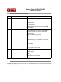
5
Broadcast confirmation report
This report will be manually or automatically printed out
the broadcast confirmation report.
(MENU key --> Report Print)
See Fig. 1-6-5-1, Fig. 1-6-5-2, Fig. 1-6-5-3, Fig. 1-6-5-4 and Fig.
1-6-5-5
6
Configuration report
This report will be manually printed out for maintenance
purpose.
(MENU key --> Report Print)
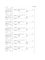
See Fig. 1-6-6-1, Fig. 1-6-6-2, Fig. 1-6-6-3, Fig. 1-6-6-4, and Fig.
1-6-6-5
7
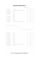
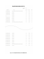
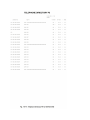
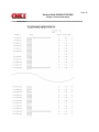
Telephone directory
This report will be manually printed out and print destinations
registered only.
(MENU key --> Report Print)
See Fig. 1-6-7-1, Fig. 1-6-7-2, Fig. 1-6-7-3, Fig. 1-6-7-4, Fig.
1-6-7-5, Fig. 1-6-7-6, Fig. 1-6-7-7, Fig. 1-6-7-8, Fig. 1-6-7-9, Fig.
1-6-7-10, Fig. 1-6-7-11, Fig. 1-6-7-12, Fig. 1-6-7-13, and Fig.
1-6-7-14.
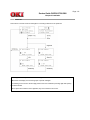
8
Power outage report
If received communications are lost due to power failure,
this report is printed out automatically at power recovery.
The information printed on the Power outage report is not
printed out on the Activity report.
See Fig. 1-6-8
9
Confidential reception report
This report will be informed operator about a stored
confidential messages in the memory and automatically
printed out.
See Fig. 1-6-9
10
Protocol dump (G3)
This report will be manually printed out for maintenance
purpose.
If the previous communication is G3, G3 communication
protocol dump is printed out.
(MENU key --> Report Print)
See Fig. 1-6-10-1 and Fig. 1-6-10-2
11
Self-diagnosis report
This report will be manually printed out for maintenance
purpose.
(To check ROMs, RAMs and Printing function.)
(MENU key --> RESOLUTION key twice --> Technical
PRG --> Local Test --> Self-diagnosis)
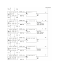
See Fig. 1-6-11-1 and Fig. 1-6-11-2
12
Log report
This report will be manually printed out for fault analysis.
(MENU key --> Report Print)
See Fig. 1-6-12
13
Function list
This list can be printed out manually from the report
operation.
This list is printed out user function only and does not print
technical function.
(MENU key --> Report Print)
See Fig. 1-6-13-1, Fig. 1-6-13-2, Fig. 1-6-13-3, Fig. 1-6-13-4,
Fig. 1-6-13-5, and Fig. 1-6-13-6.
14
Group directory
This list can be printed out manually for a selected group
only (Group #1 to #20) through operation. This list cannot
output all group at a time.
If Group is omitted, report will not be printed out.
(MENU: No. 8 --> Report Print: No. 4
See Fig.1-6-14-1, Fig.1-6-14-2, Fig.1-6-14-3, and Fig. 1-6-14-4.
15
Protocol dump (G4)
This report will be manually printed out for maintenance
purpose.
If it is G4, the G4 communication protocol dump is printed
out.
(MENU: No. 8 --> Report Print: No. 8)
See Fig. 1-6-15-1 and Fig. 1-6-15-2
16
NIC (Network Interface Card)
configuration
This report will be manually printed out for maintenance
purpose.
(MENU: No. 8 --> Report Print: No. 9
See Fig. 1-6-16-1 and Fig. 1-6-16-2
This report is not available for localization.
Copyright 1998, Okidata, Division of OKI America, Inc. All rights reserved. See the OKIDATA Business Partner
Exchange (BPX) for any updates to this material. (http://bpx.okidata.com)
Page: 21
Service Guide OKIFAX 5700/5900
Chapter 1 General Information
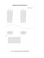
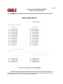
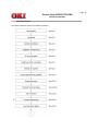
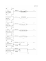
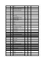
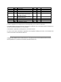
1.6.1 Shows Reports and Lists (2/2)
Active Memory Files P1
Active Memory Files P2
Active Memory Files
Activity Report
Message Confirmation (Normal report)
Message Confirmation (Error report)
Broadcast Entry Report P1
Broadcast Entry Report P2
Broadcast Entry Report P1
Broadcast Entry Report P2
Broadcast Entry Report (Broadcast TX)
Broadcast Confirmation Report P1
Broadcast Confirmation Report P2
Broadcast Confirmation Report P1
Broadcast Confirmation Report P2
Broadcast Confirmation Report (Broadcast TX by Speed Dial)
Configuration P1
Configuration P2
Configuration P3
Configuration P1
Configuration P2
Telephone Directory P1
Telephone Directory P2
Telephone Directory P3
Telephone Directory P4
Telephone Directory P5
Telephone Directory P1
Telephone Directory P2
Telephone Directory P3
Telephone Directory P4
Telephone Directory P5
Telephone Directory P6
Telephone Directory P7
Telephone Directory P8
Telephone Directory (Speed dial)
Power Outage Report
Confidential RX Report
Protocol Dump P1
Protocol Dump P2
Self Diagnosis Report
Function List P1
Function List P2
Function List P3
Function List P1
Function List P2
Function List P3
Group Directory
Group Directory P1
Group Directory P2
Group Directory (Speed dial)
Protocol Dump P1
Protocol Dump P2
NIC Configuration
Banner Sheet
Copyright 1998, Okidata, Division of OKI America, Inc. All rights reserved. See the OKIDATA Business Partner
Exchange (BPX) for any updates to this material. (http://bpx.okidata.com)
Page: 22
Service Guide OKIFAX 5700/5900
Chapter 1 General Information
Active Memory Files P1
Copyright 1998, Okidata, Division of OKI America, Inc. All rights reserved. See the OKIDATA Business Partner
Exchange (BPX) for any updates to this material. (http://bpx.okidata.com)
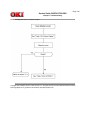
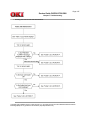
Page: 23
Service Guide OKIFAX 5700/5900
Chapter 1 General Information
Active Memory Files P2
Copyright 1998, Okidata, Division of OKI America, Inc. All rights reserved. See the OKIDATA Business Partner
Exchange (BPX) for any updates to this material. (http://bpx.okidata.com)
Page: 24
Service Guide OKIFAX 5700/5900
Chapter 1 General Information
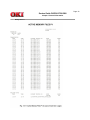
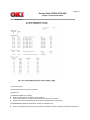
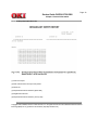
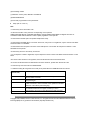
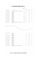
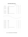
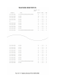
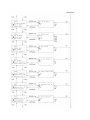
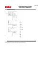
Active Memory Files
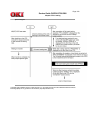
(1) Title of the report
(2) Date and time when the report was printed
(3) Sender ID
(4) RECEPTION (Memory reception)
Prints the information of no paper/no toner reception
Entries is the number of received communication times stored in the memory.
Pages is the number of total pages of the reception messages stored in the memory.
l
l
l
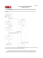
(5) TRANSMISSION (Delayed transmission, standby of redial, Batch TX)
l
Prints the information of Delay memory transmission and Redial. However, Polling RX information is printed out
l
on the below item 6.
Prints the communication date and time, distant station ID, Mode and Pages
(6) POLLING TX/RX
l
l
l
Prints the information of Polling RX or Polling TX.
Polling TX prints Mode column and number of read pages. When Feeder Polling TX, the number of read pages
is a blank.
Polling RX prints the communication date and time, distant station ID and Mode.
(7) PERSONAL BOX (Confidential, Bulletin Poll)
l
l
l
l
Prints the opened condition of Personal Box.
Mode shows the type of Box.
Entries prints the number of receipt times stored in the memory.
Pages prints the number of total pages of each Box.
Copyright 1998, Okidata, Division of OKI America, Inc. All rights reserved. See the OKIDATA Business Partner
Exchange (BPX) for any updates to this material. (http://bpx.okidata.com)
Page: 25
Service Guide OKIFAX 5700/5900
Chapter 1 General Information
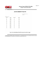
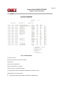
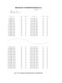
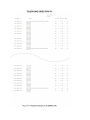
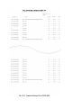
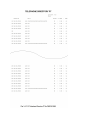
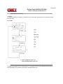
Activity Report
(1) Title of the report
(2) Date and time when the report was printed.
(3) Sender ID
(4) Total TX and total RX time
(5) Date of transmission or reception
(6) Time when the communication started
(7) Length of time for which the OKIFAX 5700/5900 was connected to the line
(8) Identification of the remote station
l
Personal ID/CSI(TSI)/Location ID/Dial number/Called TID/Calling TID
(9) Mode of the communication
l
CALLING/CALLED(Memory reception)/ CONF=XX(Confidential reception)/B.C.(Broadcast TX)/ POLLED(Polling
TX)/POLL=XX(Bulletin Poll TX)/CALLING-G4(G4 TX)/FWD-T/FWD-R/BATCH
XX=Box No.
(10) Total number of pages
(11) Result of the communication
l
OK/NO/STOP/BUSY/PAPER/COMP(Completion of a broadcast)/S JAM/R JAM/COVER/CANCEL/PUNIT
(12) Service code
Copyright 1998, Okidata, Division of OKI America, Inc. All rights reserved. See the OKIDATA Business Partner
Exchange (BPX) for any updates to this material. (http://bpx.okidata.com)
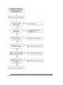
Page: 26
Service Guide OKIFAX 5700/5900
Chapter 1 General Information
Message Confirmation (Normal Report)
Copyright 1998, Okidata, Division of OKI America, Inc. All rights reserved. See the OKIDATA Business Partner
Exchange (BPX) for any updates to this material. (http://bpx.okidata.com)
Page: 27
Service Guide OKIFAX 5700/5900
Chapter 1 General Information
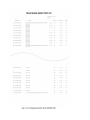
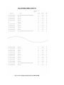
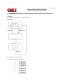
Memory Confirmation (Error Report)
(1) Title of the report
(2) Date and time when the report was printed.
(3) Sender ID
(4) Total TX and total RX time
(5) Date of transmission or reception
(6) Time when the communication started
(7) Length of time for which the OKIFAX 5700/5900 was connected to the line
(8) Identification of the remote station
l
Personal ID/CSI(TSI)/Location ID/Dial number/Called TID/Calling TID
(9) Mode of the communication
l
CALLING/CALLED(Memory reception)/CONF=XX(Confidential reception)/B.C.(Broadcast TX)/POLLED(Polling
TX)/POLL=XX(Bulletin Poll TX)/CALLING-G4(G4 TX)/FWD-T/FWD-R/BATCH
XX=Box No.
(10) Total number of pages
(11) Result of the communication
l
OK/NO/STOP/BUSY/PAPER/COMP(Completion of a broadcast)/S JAM/RJAM/ *COVER/CANCEL/PUNIT
(12) Service code
(13) Message
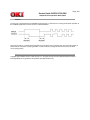
(14) Fig. 1-6-3-2 (error report)
l
l
Number of pages stored in memory
Page number is printed only in case transmission from memory is carried out.
Page numbers of the pages to which an RTN signal or PIN signal received.
The asterisk ( * ) mark indicates that retransmission of the page met the criteria of copy quality.
Copyright 1998, Okidata, Division of OKI America, Inc. All rights reserved. See the OKIDATA Business Partner
Exchange (BPX) for any updates to this material. (http://bpx.okidata.com)
Page: 28
Service Guide OKIFAX 5700/5900
Chapter 1 General Information
Broadcast Entry Report P1
Copyright 1998, Okidata, Division of OKI America, Inc. All rights reserved. See the OKIDATA Business Partner
Exchange (BPX) for any updates to this material. (http://bpx.okidata.com)
Page: 29
Service Guide OKIFAX 5700/5900
Chapter 1 General Information
Broadcast Entry Report P2
Copyright 1998, Okidata, Division of OKI America, Inc. All rights reserved. See the OKIDATA Business Partner
Exchange (BPX) for any updates to this material. (http://bpx.okidata.com)
Page: 30
Service Guide OKIFAX 5700/5900
Chapter 1 General Information
Broadcast Entry Report P1
Copyright 1998, Okidata, Division of OKI America, Inc. All rights reserved. See the OKIDATA Business Partner
Exchange (BPX) for any updates to this material. (http://bpx.okidata.com)
Page: 31
Service Guide OKIFAX 5700/5900
Chapter 1 General Information
Broadcast Entry Report P2
Copyright 1998, Okidata, Division of OKI America, Inc. All rights reserved. See the OKIDATA Business Partner
Exchange (BPX) for any updates to this material. (http://bpx.okidata.com)
Page: 32
Service Guide OKIFAX 5700/5900
Chapter 1 General Information
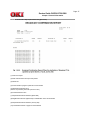
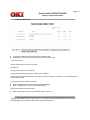
Broadcast Entry Report (Broadcast TX)
(1) Title of the report
(2) Date and time when the report was printed
(3) Sender ID
(4) Required transmission address (Speed dial)
(5) Registered location ID
(6) Required transmission address (Ten key dial)
Copyright 1998, Okidata, Division of OKI America, Inc. All rights reserved. See the OKIDATA Business Partner
Exchange (BPX) for any updates to this material. (http://bpx.okidata.com)
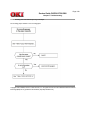
Page: 33
Service Guide OKIFAX 5700/5900
Chapter 1 General Information
Broadcast Confirmation Report P1
Copyright 1998, Okidata, Division of OKI America, Inc. All rights reserved. See the OKIDATA Business Partner
Exchange (BPX) for any updates to this material. (http://bpx.okidata.com)
Page: 34
Service Guide OKIFAX 5700/5900
Chapter 1 General Information
Broadcast Confirmation Report P2
Copyright 1998, Okidata, Division of OKI America, Inc. All rights reserved. See the OKIDATA Business Partner
Exchange (BPX) for any updates to this material. (http://bpx.okidata.com)
Page: 35
Service Guide OKIFAX 5700/5900
Chapter 1 General Information
Broadcast Confirmation Report P1
Copyright 1998, Okidata, Division of OKI America, Inc. All rights reserved. See the OKIDATA Business Partner
Exchange (BPX) for any updates to this material. (http://bpx.okidata.com)
Page: 36
Service Guide OKIFAX 5700/5900
Chapter 1 General Information
Broadcast Confirmation Report P2
Copyright 1998, Okidata, Division of OKI America, Inc. All rights reserved. See the OKIDATA Business Partner
Exchange (BPX) for any updates to this material. (http://bpx.okidata.com)
Page: 37
Service Guide OKIFAX 5700/5900
Chapter 1 General Information
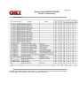
Broadcast Confirmation Report (Broadcast TX by Speed dial)
(1) Title of the report
(2) Date and time when the report was printed
(3) Sender ID
(4) Total numbers of pages in particular communication
(5) Specified transmission time
(Time is not printed by automatic print out mode.)
(6) Total transmission time
(7) Required transmission address (Speed dial)
(8) Registered location ID (Speed dial) or Identification of the remote station
(9) Required transmission address (Ten key dial)
(10) Transmitted number or pages for each address
(11) Identification of the result of communication
Copyright 1998, Okidata, Division of OKI America, Inc. All rights reserved. See the OKIDATA Business Partner
Exchange (BPX) for any updates to this material. (http://bpx.okidata.com)
Page: 38
Service Guide OKIFAX 5700/5900
Chapter 1 General Information
Configuration P1
Copyright 1998, Okidata, Division of OKI America, Inc. All rights reserved. See the OKIDATA Business Partner
Exchange (BPX) for any updates to this material. (http://bpx.okidata.com)
Page: 39
Service Guide OKIFAX 5700/5900
Chapter 1 General Information
Configuration P2
Copyright 1998, Okidata, Division of OKI America, Inc. All rights reserved. See the OKIDATA Business Partner
Exchange (BPX) for any updates to this material. (http://bpx.okidata.com)
Page: 40
Service Guide OKIFAX 5700/5900
Chapter 1 General Information
Configuration P3
Copyright 1998, Okidata, Division of OKI America, Inc. All rights reserved. See the OKIDATA Business Partner
Exchange (BPX) for any updates to this material. (http://bpx.okidata.com)
Page: 41
Service Guide OKIFAX 5700/5900
Chapter 1 General Information
Configuration P1
Copyright 1998, Okidata, Division of OKI America, Inc. All rights reserved. See the OKIDATA Business Partner
Exchange (BPX) for any updates to this material. (http://bpx.okidata.com)
Page: 42
Service Guide OKIFAX 5700/5900
Chapter 1 General Information
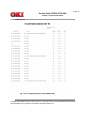
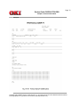
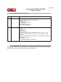
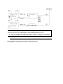
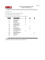
Configuration P2
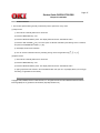
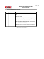
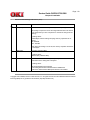
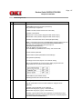
(1) Title of the report
(2) Date and time when the report was printed
(3) Sender ID
(4) User programmed function parameters
l
l
l
l
l
Machine Settings (No.10 to No.28)
Dial Options (No. 40 to No. 52)
Incoming Options (No. 60 to No.67)
Report Options (No. 70 to No. 73)
LAN Options (No. 80 to No. 82)
(5) Telephone number
(6) Forwarding number
(7) ISDN-TID: Country code, ISDN No. and ISDN ID
(8) ISDN-SUB Address
(9) Technical programmed function parameters
l
Setup (No. 01 to No. 37)
Note:
*1: Printed only when Service Bit = ON.
*2: When Service Bit = OFF, printed or not depending on the xpara bit.
USER FUNCTION SETUP > MACHINE SETTINGS > No.26: POWER SAVE MODE is skipped at the time of
COUNTRY CODE=USA of DEFAULT TYPE=1(ODA) regardless of the xpara bit.
*3: Printed when the MFP option is specified in Mfpunlock setup.
*4: Printed when the ISDN option is mounted. At this time, if any item is not registered, only the content is left blank
and its line itself is not left blank.
*5: Printed when the LAN option is mounted. If the LAN option is not mounted. all setup items in SETUP > LAN
OPTIONS are not printed.
*6: Printed only when the second tray is mounted.
*7: If no telephone number is registered, only the telephone number column is left blank and its line itself is not left
blank.
*8: If the ID of this machine is not registered, the ID is left blank and its line itself is left blank.
*9: The item is left blank when an ISDN board is mounted. However, printed when Service Bit = ON.
*10: Printed only when the machine is OKIFAX5900.
*11: Machine setting No. 26 (power save mode) is not printed when the ISDN/LAN board is mounted.
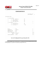
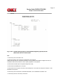
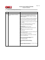
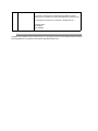
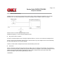
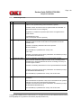
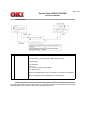
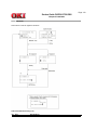
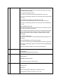
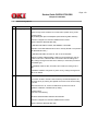
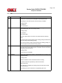
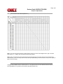
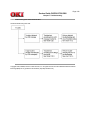
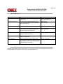
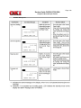
Error Name
(Decimal code)
Error Description
HSP Error 10
Command was sent to the HSP card but its response was not
returned within 5 seconds.
The Status Window did not show in the initial state 10 seconds
after powering on.
Received the operation command during the POWER ON mode if
it takes 3 seconds or more to transfer to the operation mode after
clearance of the initial synchronizing flag.
In the Reverse Data command, the HSP card could not transmit all
the notification data from the higher modules. (In case a
communication error has occurred between the HSP and host.)
Others
HSP Error 20
HSP Error 21
HSP Error 22
HSP Error 00
Copyright 1998, Okidata, Division of OKI America, Inc. All rights reserved. See the OKIDATA Business Partner
Exchange (BPX) for any updates to this material. (http://bpx.okidata.com)
Page: 43
Service Guide OKIFAX 5700/5900
Chapter 1 General Information
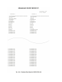
Telephone Directory P1
Copyright 1998, Okidata, Division of OKI America, Inc. All rights reserved. See the OKIDATA Business Partner
Exchange (BPX) for any updates to this material. (http://bpx.okidata.com)
Page: 44
Service Guide OKIFAX 5700/5900
Chapter 1 General Information
Telephone Directory P2
Copyright 1998, Okidata, Division of OKI America, Inc. All rights reserved. See the OKIDATA Business Partner
Exchange (BPX) for any updates to this material. (http://bpx.okidata.com)
Page: 45
Service Guide OKIFAX 5700/5900
Chapter 1 General Information
Telephone Directory P3
Copyright 1998, Okidata, Division of OKI America, Inc. All rights reserved. See the OKIDATA Business Partner
Exchange (BPX) for any updates to this material. (http://bpx.okidata.com)
Page: 46
Service Guide OKIFAX 5700/5900
Chapter 1 General Information
Telephone Directory P4
Copyright 1998, Okidata, Division of OKI America, Inc. All rights reserved. See the OKIDATA Business Partner
Exchange (BPX) for any updates to this material. (http://bpx.okidata.com)
Page: 47
Service Guide OKIFAX 5700/5900
Chapter 1 General Information
Telephone Directory P5
Copyright 1998, Okidata, Division of OKI America, Inc. All rights reserved. See the OKIDATA Business Partner
Exchange (BPX) for any updates to this material. (http://bpx.okidata.com)
Page: 48
Service Guide OKIFAX 5700/5900
Chapter 1 General Information
Telephone Directory P1
Copyright 1998, Okidata, Division of OKI America, Inc. All rights reserved. See the OKIDATA Business Partner
Exchange (BPX) for any updates to this material. (http://bpx.okidata.com)
Page: 49
Service Guide OKIFAX 5700/5900
Chapter 1 General Information
Telephone Directory P2
Copyright 1998, Okidata, Division of OKI America, Inc. All rights reserved. See the OKIDATA Business Partner
Exchange (BPX) for any updates to this material. (http://bpx.okidata.com)
Page: 50
Service Guide OKIFAX 5700/5900
Chapter 1 General Information
Telephone Directory P3
Copyright 1998, Okidata, Division of OKI America, Inc. All rights reserved. See the OKIDATA Business Partner
Exchange (BPX) for any updates to this material. (http://bpx.okidata.com)
Page: 51
Service Guide OKIFAX 5700/5900
Chapter 1 General Information
Telephone Directory P4
Copyright 1998, Okidata, Division of OKI America, Inc. All rights reserved. See the OKIDATA Business Partner
Exchange (BPX) for any updates to this material. (http://bpx.okidata.com)
Page: 52
Service Guide OKIFAX 5700/5900
Chapter 1 General Information
Telephone Directory P5
Copyright 1998, Okidata, Division of OKI America, Inc. All rights reserved. See the OKIDATA Business Partner
Exchange (BPX) for any updates to this material. (http://bpx.okidata.com)
Page: 53
Service Guide OKIFAX 5700/5900
Chapter 1 General Information
Telephone Directory P6
Copyright 1998, Okidata, Division of OKI America, Inc. All rights reserved. See the OKIDATA Business Partner
Exchange (BPX) for any updates to this material. (http://bpx.okidata.com)
Page: 54
Service Guide OKIFAX 5700/5900
Chapter 1 General Information
Telephone Directory P7
Copyright 1998, Okidata, Division of OKI America, Inc. All rights reserved. See the OKIDATA Business Partner
Exchange (BPX) for any updates to this material. (http://bpx.okidata.com)
Page: 55
Service Guide OKIFAX 5700/5900
Chapter 1 General Information
Telephone Directory P8
Copyright 1998, Okidata, Division of OKI America, Inc. All rights reserved. See the OKIDATA Business Partner
Exchange (BPX) for any updates to this material. (http://bpx.okidata.com)
Page: 56
Service Guide OKIFAX 5700/5900
Chapter 1 General Information
Telephone Directory (Speed dial)
l
l
Five pages for OKIFAX 5700 and eight pages for OKIFAX 5900.
SPEED DIAL: Up to 140 for OKIFAX 5700, up to 230 for OKIFAX 5900
(1) Title of the report
(2) Date and time when the report was printed
(3) Sender ID
(4) Programmed ID (up to 15 characters)
(5) Programmed Speed Dial telephone numbers (Up to 40 digits)
(6) Programmed alternative destination (ALT#: alternate TEL No.) telephone numbers #: 1 to 40 for OKIFAX 5700, 1
to 80 for OKIFAX 5900
(7) Programmed communication parameters
l
l
When an ISDN board is mounted: G3-ECHO/G3-RATE/MODE
When no ISDN board is mounted: G3-ECHO/G3-RATE
(8) Programmed batch transmission time
l
Batch transmission time can be set for SPEED DIAL 31 to 40 only.
Copyright 1998, Okidata, Division of OKI America, Inc. All rights reserved. See the OKIDATA Business Partner
Exchange (BPX) for any updates to this material. (http://bpx.okidata.com)
Page: 57
Service Guide OKIFAX 5700/5900
Chapter 1 General Information
Power Outage Report
(1) Title of the report
(2) Date and time when the report was printed
(3) Sender ID
(4) Reserved/transmission date
(5) Reserved/transmission time
(6) Communication time
(7) Identification of the remote station
(8) Mode of the communication
CONF (Confidential reception)/CALLED (Memory reception)/B.C. (Broadcast TX)
(9) Total number of reserved documents or transmitted pages
(10) Result of the communication
LOST
Copyright 1998, Okidata, Division of OKI America, Inc. All rights reserved. See the OKIDATA Business Partner
Exchange (BPX) for any updates to this material. (http://bpx.okidata.com)
Page: 58
Service Guide OKIFAX 5700/5900
Chapter 1 General Information
Confidential RX Report
(1) Title of the report
(2) Date and time when the report was printed.
(3) Sender ID
(4) Date of transmission or reception
(5) Time when the communication started
(6) Length of time for which the OKIFAX 5700/5900 was connected to the line
(7) Identification of the remote station
(8) Mode of the communication
l
l
The stored confidential box number is printed in the MODE column.
CONF=01 (box number)
(9) Total number of pages
(10) Result of the communication
(11) Service code
Copyright 1998, Okidata, Division of OKI America, Inc. All rights reserved. See the OKIDATA Business Partner
Exchange (BPX) for any updates to this material. (http://bpx.okidata.com)
Page: 59
Service Guide OKIFAX 5700/5900
Chapter 1 General Information
Protocol Dump P1
Copyright 1998, Okidata, Division of OKI America, Inc. All rights reserved. See the OKIDATA Business Partner
Exchange (BPX) for any updates to this material. (http://bpx.okidata.com)
Page: 60
Service Guide OKIFAX 5700/5900
Chapter 1 General Information
Protocol Dump P2
(1) Title of the report
(2) Date and time when the report was printed
(3) Sender ID
(4) Date of communication
(5) Time of communication
(6) One message transmission/reception time
(7) Identification of remote station
l
CSI and/or telephone number
(8) Mode of transmission/reception according to ITU-T designation
(9) Total number of pages in communication
(10) Identification of the result of the communication
(11) Service code
(12) TX: DIS/DTC/DCS/NSF/NSS/NSC
(13) Transmitted telephone number
(14) Transmitted SEP/SUB
(15) Common information of ITU-T V.34 TX/RX
(16) Modem trace
(17) RX: DIS/DTC/DCS/NSF/NSS/NSC
(18) Received telephone number
(19) Received SEP/SUB
(20) Common information of ITU-T V.34 TX/RX
(21) Modem trace
Copyright 1998, Okidata, Division of OKI America, Inc. All rights reserved. See the OKIDATA Business Partner
Exchange (BPX) for any updates to this material. (http://bpx.okidata.com)
Page: 61
Service Guide OKIFAX 5700/5900
Chapter 1 General Information
Self Diagnosis Report
Note:
*1: a indicates an alphanumeric character; n indicates a numeric character (0 to 9); h indicates a hexadecimal
number; and b indicates 0 or 1.
*2: Printed when the option memory board is mounted and if not, entry lines following
this line are not omitted.
*3: This item is left blank when MFP AVAIL is OFF. Lowercase letters can also be listed. This item reports MDL
information for the PnP device ID only.
This item can be up to 40 characters long.
*4: This item reports toner cartridge ID information (port read value).
*5: For the LAN board, the status of the LAN board at self diagnosis shall be recorded. (If the LAN board is in the
alarm state, the cause of the alarm is recorded.) When an HSP error occurs, entry items shown below are printed.
HSP NG nn
*6: The result of ISDN board test, which is performed at self diagnosis, shall be printed. (Error information at
power-on shall also be listed partially.)
When an ISDN error occurs, entry items shown below are printed.
ISDN BOARD NG nn
nn=01 Waiting for PC loading
The BOOT2 signal from the host side at the time of power on is set to PC loading mode.
nn=02 Board abnormality
The ISDN board program hash is NG upon power on.
nn=03 Board abnormality
The initial sequence between boards cannot be executed in 10 seconds after power on. (The status window does not
indicate a normal value.)
nn=04 Board abnormality
The initial sequence of the ISDN LSI cannot be executed upon power on.
(No response for the command, NG response)
nn=05 ISDN LSI abnormality
The result of ISDN LSI testing function is NG: (ROM/RAM test, Loop test)
Copyright 1998, Okidata, Division of OKI America, Inc. All rights reserved. See the OKIDATA Business Partner
Exchange (BPX) for any updates to this material. (http://bpx.okidata.com)
Page: 62
Service Guide OKIFAX 5700/5900
Chapter 1 General Information
Function List P1
Copyright 1998, Okidata, Division of OKI America, Inc. All rights reserved. See the OKIDATA Business Partner
Exchange (BPX) for any updates to this material. (http://bpx.okidata.com)
Page: 63
Service Guide OKIFAX 5700/5900
Chapter 1 General Information
Function List P2
Copyright 1998, Okidata, Division of OKI America, Inc. All rights reserved. See the OKIDATA Business Partner
Exchange (BPX) for any updates to this material. (http://bpx.okidata.com)
Page: 64
Service Guide OKIFAX 5700/5900
Chapter 1 General Information
Function List P3
Copyright 1998, Okidata, Division of OKI America, Inc. All rights reserved. See the OKIDATA Business Partner
Exchange (BPX) for any updates to this material. (http://bpx.okidata.com)
Page: 65
Service Guide OKIFAX 5700/5900
Chapter 1 General Information
Function List P1
Copyright 1998, Okidata, Division of OKI America, Inc. All rights reserved. See the OKIDATA Business Partner
Exchange (BPX) for any updates to this material. (http://bpx.okidata.com)
Page: 66
Service Guide OKIFAX 5700/5900
Chapter 1 General Information
Function List P2
Copyright 1998, Okidata, Division of OKI America, Inc. All rights reserved. See the OKIDATA Business Partner
Exchange (BPX) for any updates to this material. (http://bpx.okidata.com)
Page: 67
Service Guide OKIFAX 5700/5900
Chapter 1 General Information
Function List P3
Note:
*1: Printed only when Service Bit = ON.
*2: When Service Bit = OFF, printed or not depending on the xpare bit.
USER FUNCTION SETUP > MACHINE SETTINGS > No.26: POWER SAVE MODE is skipped at the time of
COUNTRY CODE=USA of DEFAULT TYPE=1(ODA) regardless of *the xpara bit.
*3: Printed when the MFP option is specified in Mfpunlock setup.
*4: Printed when the ISDN option is mounted.
*5: Printed when the LAN option is mounted. If the LAN option is not mounted. all setup items in SETUP > LAN
OPTIONS are not printed.
*6: Printed only when User SETUP > MACHINE SETTINGS > No.19: RESTRICT ACCESS = ON.
*7: Printed only when the second tray is mounted.
*8: Printed when Technical SETUP > No.33: TONER COUNTER CLEAR = ON, even if Service Bit = OFF.
*9: If the ID of this machine is not registered, the ID is left blank and its line itself is not left blank.
*10: The item is left blank when an ISDN board is mounted. However, printed when Service Bit = ON.
*11:
FAX, TEL, MEM., and FWD are always listed.
l
T/F is listed when the ISDN board is not mounted and TEL/FAX switch is set to ON.(Technical setup: 08)
l
TAD is listed when the ISDN board is not mounted and TAD mode is set to ON. (Technical
setup: 06)
l
When all description conditions are met, modes must be described in the "FAX --> TEL --> TF --> TAD --> MEM
--> PC --> FWD" sequence. If any description condition is not met for a mode, the mode must be omitted and
the succeeding modes must be moved up.
Example: ISDN board installed, MFP = ON: FAX/TEL/MEM/PC/FWD
*12: When National code is set to FRE, the following setting values are listed.
l
l
Redial tries: 1 to 5 (in one-try steps)
Redial interval: 1 to 12 (in one-minute steps)
*13: Machine setting No. 26 (power save mode) is not printed when the ISDN/LAN board is mounted.
Copyright 1998, Okidata, Division of OKI America, Inc. All rights reserved. See the OKIDATA Business Partner
Exchange (BPX) for any updates to this material. (http://bpx.okidata.com)
Page: 68
Service Guide OKIFAX 5700/5900
Chapter 1 General Information
Group Directory
Copyright 1998, Okidata, Division of OKI America, Inc. All rights reserved. See the OKIDATA Business Partner
Exchange (BPX) for any updates to this material. (http://bpx.okidata.com)
Page: 69
Service Guide OKIFAX 5700/5900
Chapter 1 General Information
Group Directory P1
Copyright 1998, Okidata, Division of OKI America, Inc. All rights reserved. See the OKIDATA Business Partner
Exchange (BPX) for any updates to this material. (http://bpx.okidata.com)
Page: 70
Service Guide OKIFAX 5700/5900
Chapter 1 General Information
Group Directory P2
Copyright 1998, Okidata, Division of OKI America, Inc. All rights reserved. See the OKIDATA Business Partner
Exchange (BPX) for any updates to this material. (http://bpx.okidata.com)
Page: 71
Service Guide OKIFAX 5700/5900
Chapter 1 General Information
Group Directory (Speed dial)
(1) Title of the list
(2) Date and time when the list was printed
(3) Sender ID
(4) Registered Group No. and ID
(5) Registered location ID (up to 15 characters)
Copyright 1998, Okidata, Division of OKI America, Inc. All rights reserved. See the OKIDATA Business Partner
Exchange (BPX) for any updates to this material. (http://bpx.okidata.com)
Page: 72
Service Guide OKIFAX 5700/5900
Chapter 1 General Information
Protocol Dump P1
Copyright 1998, Okidata, Division of OKI America, Inc. All rights reserved. See the OKIDATA Business Partner
Exchange (BPX) for any updates to this material. (http://bpx.okidata.com)
Page: 73
Service Guide OKIFAX 5700/5900
Chapter 1 General Information
Protocol Dump P2
(1) Title of the report
(2) Date and time when the report was printed
(3) Sender ID
(4) Date of communication
(5) Time of communication
(6) One message transmission/reception time
(7) Identification of remote station
l
CSI and/or telephone number
(8) Mode of transmission/reception according to ITU-T designation
(9) Total number of pages in communication
(10) Identification of the result of the communication
(11) Service code
(12) D channel
(13) B channel
(14) COMMN MODE
(15) COMMN SPEED
(16) FLOW CONTROL PARAM.
(17) TID
(18) SETUP
(19) DISC
(20) CR/CN, CA/CC, CQ/CI, RQ/RI, SQ/SI
(21) TBR/TCC/TCR/TCA
(22) CSS
(23) RSSP/RSSN
(24) CD/CL
(25) RDCLP
(26) CDS
(27) CDUI
Copyright 1998, Okidata, Division of OKI America, Inc. All rights reserved. See the OKIDATA Business Partner
Exchange (BPX) for any updates to this material. (http://bpx.okidata.com)
Page: 74
Service Guide OKIFAX 5700/5900
Chapter 1 General Information
NIC Configuration
Copyright 1998, Okidata, Division of OKI America, Inc. All rights reserved. See the OKIDATA Business Partner
Exchange (BPX) for any updates to this material. (http://bpx.okidata.com)
Page: 75
Service Guide OKIFAX 5700/5900
Chapter 1 General Information
Banner Sheet
Copyright 1998, Okidata, Division of OKI America, Inc. All rights reserved. See the OKIDATA Business Partner
Exchange (BPX) for any updates to this material. (http://bpx.okidata.com)
Page: 76
Service Guide OKIFAX 5700/5900
Chapter 2 Installation
2.1 General Setup Information
The following flowchart outlines the installation procedure.
#1: For operation and registration, see OKIFAX 5700/5900 Handbook.
#2: Memory board, G4 option board, LAN option board, Second cassette unit etc.,.
Copyright 1998, Okidata, Division of OKI America, Inc. All rights reserved. See the OKIDATA Business Partner
Exchange (BPX) for any updates to this material. (http://bpx.okidata.com)
Page: 77
Service Guide OKIFAX 5700/5900
Chapter 2 Installation
2.2 Site Selection
INSTALLATION
Precautions for Installation
1 Fluctuation in line voltage
l
l
2
3
4
5
6
7
8
120V AC (102V to 127V)
230V AC (198V to 264V)
Room temperature
l 50 to 90 degrees Fahrenheit (10 to 32 degrees Celsius)
Humidity
l 20 to 80% RH
Operating environment
l Pressure: Equivalent to altitude of 2500m (8020 feet) and below.
Exposure
l Within five minutes at luminous intensity 2,000 lux.
Required space for installation
l The facsimile requires the space as shown below for safety and good operability.
Levelness of installation surface
l 1 degree maximum.
Other requirements
Avoid installing in any of the following places:
l A place exposed to direct sunlight
l A place near a heat source or exposed to vibration
l A dusty place
l A place in the atmosphere of acid gas, or steam etc.
l A place exposed to quick temperature changes
Note:
1 This space is necessary for having the telephone set.
2 This space is necessary for removing the recording paper cassette.
3 This space is necessary for installing the document stacker and allow space for the fan exhaust.
Copyright 1998, Okidata, Division of OKI America, Inc. All rights reserved. See the OKIDATA Business Partner
Exchange (BPX) for any updates to this material. (http://bpx.okidata.com)
Page: 78
Service Guide OKIFAX 5700/5900
Chapter 2 Installation
2.3 Unpacking
Procedure
1 Remove tape on the top of the carton box and open its cover.
Figure 2.3.1.1 Unpacking Procedure (1)
2 Take out the accessory box from the carton box. (See Figure below 2.3)
3 Take out the machine with plastic wrapper from the box.
Copyright 1998, Okidata, Division of OKI America, Inc. All rights reserved. See the OKIDATA Business Partner
Exchange (BPX) for any updates to this material. (http://bpx.okidata.com)
Page: 79
Service Guide OKIFAX 5700/5900
Chapter 2 Installation
2.4 Check of Contents
Table 2.4.1 Contents List for OKIFAX 5700/5900
After having taken out the machine and accompanied accessories from the carton box, check the contents according
to the following list:
Item
No.
1
2
3
4
5
6
7
8
Name
OKIFAX 5700/5900 facsimile
AC power cord
I/D unit
Toner cartridge
Document stacker
Telephone line code
Once touch sheet
User's Guide
Quantity
1
1
1
1
1
1
1
1
Remarks
Already installed.
Already installed.
1 volume
Copyright 1998, Okidata, Division of OKI America, Inc. All rights reserved. See the OKIDATA Business Partner
Exchange (BPX) for any updates to this material. (http://bpx.okidata.com)
Page: 80
Service Guide OKIFAX 5700/5900
Chapter 2 Installation
2.5 Installation of Attachments
1 Items
l
l
l
l
Image Drum (ID) Unit (already installed)
Toner cartridge
Recording paper
Document stacker
2 Procedure
1) Toner cartridge
l
l
Peel off the fixed tape attached to the tray-paper.
Open the cover-top.
Figure 2.5.1 Toner Cartridge Installation (1)
l
Take out the plastic cover out of the ID unit.
Figure 2.5.2 Toner Cartridge Installation (2)
l
Take out the toner cartridge from the damp proof bag, shake it five or six times as shown in the illustration to
eliminate the toner deflection, and peel off the seal gently.
Figure 2.5.3 Toner Cartridge Installation (3)
l
l
Ensure that the plastic tab on the right-hand side of the toner cartridge recess lines up with the groove on the
toner cartridge.
Press down on both ends to make sure the cartridge is fully seated.
Figure 2.5.4 Toner Cartridge Installation (4)
l
Push the gray tab forward until it stops.
l
l
Clean the toner scattered in the vicinity of the toner cartridge using a cloth moistened with cold
water. Do not use hot water since it makes the toner stick there.
Close the cover assembly-top until the buttons have been locked completely.
3 Recording paper
Note: About 250 sheets of the new paper can be set in the recording paper cassette.
l
Remove the paper cassette from the facsimile by pulling the cassette tab.
l
Sheets must not exceed the paper full marker of the new paper limit indication. If excessive sheets are
set, it will
cause paper jams.
l After loading the new paper, push it forward into the slot at the front of the facsimile until it locks.
4 Document stacker
l
Hang the document stacker onto hanging position.
Copyright 1998, Okidata, Division of OKI America, Inc. All rights reserved. See the OKIDATA Business Partner
Exchange (BPX) for any updates to this material. (http://bpx.okidata.com)
Page: 81
Service Guide OKIFAX 5700/5900
Chapter 2 Installation
2.6 AC Cord Connection
The power supply is provided as follows.
Normal input voltage 120V AC (Voltage range 102 to 127V AC)
Normal input voltage 230V AC (Voltage range 198 to 250 V AC)
Check whether the AC voltage of your input is within the above-mentioned voltage range and if so, check that
the power switch is turned OFF. After turning off the power switch, connect the female plug of the AC cord
to the machine and insert the male plug of the AC cord to the inlet receptacle.
Turn the power switch ON and check that the display shows "(TIME and MEMORY FREE 100%)" message
indicating the standby mode.
Copyright 1998, Okidata, Division of OKI America, Inc. All rights reserved. See the OKIDATA Business Partner
Exchange (BPX) for any updates to this material. (http://bpx.okidata.com)
Page: 82
Service Guide OKIFAX 5700/5900
Chapter 2 Installation
2.7 Telephone and Line Connections
1 Procedure
l
Connect the lines.
Copyright 1998, Okidata, Division of OKI America, Inc. All rights reserved. See the OKIDATA Business Partner
Exchange (BPX) for any updates to this material. (http://bpx.okidata.com)
Page: 83
Service Guide OKIFAX 5700/5900
Chapter 2 Installation
2.8 Packing for Shipment
CAUTION: When packing the OKIFAX 5700/5900 for shipment, REMOVE THE IMAGE DRUM AND TONER FROM
THE UNIT AND SHIP SEPARATELY!
Failure to do this will result in damage to the machine.
Copyright 1998, Okidata, Division of OKI America, Inc. All rights reserved. See the OKIDATA Business Partner
Exchange (BPX) for any updates to this material. (http://bpx.okidata.com)
Page: 84
Service Guide OKIFAX 5700/5900
Chapter 2 Installation
2.9 Initial Settings
2.9.1 General Procedure of Key Operation
2.9.2 Technical Functions: Setup
2.9.3 User's Functions
2.9.4 Location Program
2.9.5 Setup
2.9.6 User Default Setting
2.9.7 Technical Default Setting
2.9.8 Default Setting of Dial Parameters
2.9.9 Off-line Tests
2.9.10 On-line Tests
Copyright 1998, Okidata, Division of OKI America, Inc. All rights reserved. See the OKIDATA Business Partner
Exchange (BPX) for any updates to this material. (http://bpx.okidata.com)
Page: 85
Service Guide OKIFAX 5700/5900
Chapter 2 Installation
2.9.1 General Procedure of Key Operation
Note: The fonts displayed on the LCD operation panel may differ from the fonts written this manual.
Accessing to desired functions:
l
There are two methods for accessing a desired function: Step access and Speed access (direct access).
l
Step Access
To access functions in a stepwise manner, the procedure is like that described for navigating the operational layers.
Begin from pressing MENU/EXIT key, and then use the programming keys to locate, enter and set the desired
function.
l
Speed Access
If the function is assigned a speed access number, typing this number in at the menu display prompt in the first
operational layer will bring up the setting or registration display in the fourth operational layer for direct access.
Note 1 A speed access number must be entered with two digits. (It must not be entered with neither one digit nor
three digits.)
Note 2 Speed access numbers are fixed.
Some of them cannot be used (skipped) depending on the destination of delivery and whether the machine is
equipped with any option. Access numbers become discontinuous.
Copyright 1998, Okidata, Division of OKI America, Inc. All rights reserved. See the OKIDATA Business Partner
Exchange (BPX) for any updates to this material. (http://bpx.okidata.com)
Page: 86
Service Guide OKIFAX 5700/5900
Chapter 2 Installation
User Functions
Copyright 1998, Okidata, Division of OKI America, Inc. All rights reserved. See the OKIDATA Business Partner
Exchange (BPX) for any updates to this material. (http://bpx.okidata.com)
Page: 87
Service Guide OKIFAX 5700/5900
Chapter 2 Installation
2.9.2 Technical Functions
1. This section explains items generally conducted by service personnel, not by users.
(1) Step access
1) The machine is standby state with no document.
2) Press the MENU/EXIT key once.
3) Press the RESOLUTION key twice. The display will be shown the "TECHNICAL PRG.".
4) Press the SHIFT DOWN ( ) key. The menu option "2 SETUP" indicated by the blinking cursor is selected,
and press the ENTER/SHIFT RIGHT (-->) key.
5) The display will be shown "SETUP".
6) You can access a desired function by switching among menus using SHIFT keys
(2) Speed access
1) The machine is standby state with no document.
2) Press the MENU/EXIT key once.
3) Press the RESOLUTION key twice. The display will be shown the "TECHNICAL PRG.".
4) Typing a speed access number in the "TECHNICAL PRG. XX" (XX: 01 to 37) display allows you to bring up
the setting or registration screen directly.
Copyright 1998, Okidata, Division of OKI America, Inc. All rights reserved. See the OKIDATA Business Partner
Exchange (BPX) for any updates to this material. (http://bpx.okidata.com)
Page: 88
Service Guide OKIFAX 5700/5900
Chapter 2 Installation
2.9.2.1 Technical Functions Operation 1
Select Menu is shown as below:
1. Local Test
2. Technical Setup: Go to Section 2.9.2.2
3. System Reset
4. Default Type Set
5. PC Loading
6. G4 PC Loading
Copyright 1998, Okidata, Division of OKI America, Inc. All rights reserved. See the OKIDATA Business Partner
Exchange (BPX) for any updates to this material. (http://bpx.okidata.com)
Page: 89
Service Guide OKIFAX 5700/5900
Chapter 2 Installation
2.9.2.2 Technical Functions Operation 2
Copyright 1998, Okidata, Division of OKI America, Inc. All rights reserved. See the OKIDATA Business Partner
Exchange (BPX) for any updates to this material. (http://bpx.okidata.com)
Page: 90
Service Guide OKIFAX 5700/5900
Chapter 2 Installation
2.9.2.2.1 T1 (TX) Timer Value
Set the T1 timer (call connection wait time: XTTO) for transmission.
Copyright 1998, Okidata, Division of OKI America, Inc. All rights reserved. See the OKIDATA Business Partner
Exchange (BPX) for any updates to this material. (http://bpx.okidata.com)
Page: 91
Service Guide OKIFAX 5700/5900
Chapter 2 Installation
2.9.2.2.2 T1 (RX) Timer Value
Set the T1 timer for reception.
The time from issue of the first DIS to issue of a signal is checked. If a time-out occurs, the line is disconnected.
Copyright 1998, Okidata, Division of OKI America, Inc. All rights reserved. See the OKIDATA Business Partner
Exchange (BPX) for any updates to this material. (http://bpx.okidata.com)
Page: 92
Service Guide OKIFAX 5700/5900
Chapter 2 Installation
2.9.2.2.3 T2 Timer *100ms
Registers the time duration (in seconds) for which the fax detects the EOL interval during reception of phase C. The
fax disconnects the line when EOL cannot detect within T2 Timer.
Copyright 1998, Okidata, Division of OKI America, Inc. All rights reserved. See the OKIDATA Business Partner
Exchange (BPX) for any updates to this material. (http://bpx.okidata.com)
Page: 93
Service Guide OKIFAX 5700/5900
Chapter 2 Installation
2.9.2.2.4 Error Criterion
Registers the threshold value whether to transmit RTN or MCF signal when the error occurs in received data.
Copyright 1998, Okidata, Division of OKI America, Inc. All rights reserved. See the OKIDATA Business Partner
Exchange (BPX) for any updates to this material. (http://bpx.okidata.com)
Page: 94
Service Guide OKIFAX 5700/5900
Chapter 2 Installation
2.9.2.2.5 Attenuator
Adjusts the attenuation (dB) for the message send signal power level. Adjusting value is 0 to 15dB in one dB steps.
Copyright 1998, Okidata, Division of OKI America, Inc. All rights reserved. See the OKIDATA Business Partner
Exchange (BPX) for any updates to this material. (http://bpx.okidata.com)
Page: 95
Service Guide OKIFAX 5700/5900
Chapter 2 Installation
2.9.2.2.6 T/F Tone Att.
Adjusts the attenuation (dB) for the send MF tone power level. Adjusting the value is 0 to 15dB in one dB steps.
Copyright 1998, Okidata, Division of OKI America, Inc. All rights reserved. See the OKIDATA Business Partner
Exchange (BPX) for any updates to this material. (http://bpx.okidata.com)
Page: 96
Service Guide OKIFAX 5700/5900
Chapter 2 Installation
2.9.2.2.7 MF Att.
Adjusts the attenuation (dB) for the send MF tone power level. Adjusting the value is 0 to 15dB in one dB steps.
Copyright 1998, Okidata, Division of OKI America, Inc. All rights reserved. See the OKIDATA Business Partner
Exchange (BPX) for any updates to this material. (http://bpx.okidata.com)
Page: 97
Service Guide OKIFAX 5700/5900
Chapter 2 Installation
2.9.2.2.8 Ring Dura. *10ms
Selects the minimum ring detection time to meet country's requirements. Adjusting time is 100MS to 990MS in 10MS
steps.
Copyright 1998, Okidata, Division of OKI America, Inc. All rights reserved. See the OKIDATA Business Partner
Exchange (BPX) for any updates to this material. (http://bpx.okidata.com)
Page: 98
Service Guide OKIFAX 5700/5900
Chapter 2 Installation
2.9.2.2.9 CML Timing *100ms
Selects the time from end of ring to CML-ON. Adjusting time is 100MS to 1900MS in 100MS steps.
Copyright 1998, Okidata, Division of OKI America, Inc. All rights reserved. See the OKIDATA Business Partner
Exchange (BPX) for any updates to this material. (http://bpx.okidata.com)
Page: 99
Service Guide OKIFAX 5700/5900
Chapter 2 Installation
2.9.2.2.10 LED Headstrobe
Setting of LED printhead strobe signals (00000 - 11111). Selection of strobe width in LED head. "00000" is lightest
and "11111" is darkest.
Copyright 1998, Okidata, Division of OKI America, Inc. All rights reserved. See the OKIDATA Business Partner
Exchange (BPX) for any updates to this material. (http://bpx.okidata.com)
Page: 100
Service Guide OKIFAX 5700/5900
Chapter 2 Installation
Service Personnel Initial Settings Table 2.9.2.3 (1/11)
T.F.
No.
Item
Specifications
01
Service bit
Enables the serviceman to make special settings. If this setting is OFF, some
settings and report print function may become unavailable.
1) Setting values
ON: Enables the serviceman to make settings.
OFF: Disables the serviceman to make settings.
02
Monitor control
Sets up the line monitor.
If this setting is OFF at the time of transmission, the line is monitored during
dialing but the line will not be monitored after a specified time lapse (about 5
sec).
If this setting is ON, the line will be monitored till the end of communication.
1) Setting values
ON: Monitored continuously
OFF: Not monitored continuously
* The tone level can be adjusted by setting Monitor Volume.
03
Country code
1) Setting values
Select a country code:
USA/INT/GBR/IRL/NOR/SWE/FIN/DEN/GER/HUN/TCH/POL/SUI/AUT/BEL/H
OL/FRE/POR/ESP/ITA/GRE/AUS/NZL/SIN/HNG/LTA/MEX
* The setting data must be transferred to the G4 board.
* Setup a dial parameter when changing a country code.
* Distinctive ring sets to OFF.
* In case Country code is changed in FRE:
Forcibly, set to 7dB when the attenuator setting
values are set between 0dB to 6dB.
Copyright 1998, Okidata, Division of OKI America, Inc. All rights reserved. See the OKIDATA Business Partner
Exchange (BPX) for any updates to this material. (http://bpx.okidata.com)
Page: 101
Service Guide OKIFAX 5700/5900
Chapter 2 Installation
Service Personnel Initial Settings Table 2.9.2.3 (2/11)
T.F.
No.
Item
Specifications
04
Time and date print Determine whether the date and time set on the local machine are to be
printed at the beginning of the received image.
1) Setting values
OFF/ONCE/ALL selectable.
OFF: Not printed
ONCE: Printed on page 1 only
ALL: Printed on all pages
05
TSI print
Determine whether a TSI is to be printed in the received
image.
1) Setting value
ON: Printed
OFF: Not printed
* When this setting is ON and TIME/DATE PRINT is set to ALL , a TSI is
printed on all received pages. In other cases, a TSI is printed on the first
page only.
* When a TSI has not been registered but a personal ID has been registered,
the personal ID is printed.
(Reference)
TSI: Transmitting Subscriber Identification
Copyright 1998, Okidata, Division of OKI America, Inc. All rights reserved. See the OKIDATA Business Partner
Exchange (BPX) for any updates to this material. (http://bpx.okidata.com)
Page: 102
Service Guide OKIFAX 5700/5900
Chapter 2 Installation
Service Personnel Initial Settings Table 2.9.2.3 (3/11)
T.F.
No.
Item
Specifications
06
TAD mode
(For external telephone answering
device.)
Switches between TAD modes.
This setting is required to determine whether TAD is to be
selected in the AUTO ANSWER mode and set the fax
operation to be performed after completion of TAD-side
operation (response).
In the TAD mode, a message is recorded in the telephone
memory if the telephone (connected externally) answers
automatically when the facsimile is ready for reception.
After completion of message recording, the line is switched
to the facsimile.
If CNG is detected while the telephone is answering
automatically, reception starts immediately.
1) Setting values
OFF/TYPE1/TYPE2/TYPE3 selectable.
* Relationships between settings and operations are as
follows:
OFF: TAD cannot be selected in the AUTO
ANSWER mode.
TYPE1: When TAD operation ends without detecting CNG,
the line is switched to the
facsimile starting reception immediately.
TYPE2: After completion of TAD operation, the machine
returns to the standby state.
TYPE3: The machine starts detecting CNG 15
seconds after the telephone starts the
auto answering operation.
If TAD operation ends without detecting
CNG, the machine returns to the standby
state.
* When this setting is set to OFF in the TAD mode, the FAX
mode will be selected automatically.
07
Real time dialing
Determine whether real-time dialing is enabled.
If it is enabled, determine when it will be enabled.
1) Setting values
OFF/TYPE1 (External telephone is off-hooked)/TYPE2
selectable.
OFF: Real-time dialing is disabled (accumulated dialing
only)
TYPE1: Enabled when the external telephone is
off-hooked.
TYPE2: Enabled when the external telephone is off-hooked
or the HOOK key is pressed.
answering device.)
Copyright 1998, Okidata, Division of OKI America, Inc. All rights reserved. See the OKIDATA Business Partner
Exchange (BPX) for any updates to this material. (http://bpx.okidata.com)
Page: 103
Service Guide OKIFAX 5700/5900
Chapter 2 Installation
Service Personnel Initial Settings Table 2.9.2.3 (4/11)
T.F.
No.
Item
Specifications
08
TEL/FAX switching
Determine whether the TEL/FAX mode can be selected
in the AUTO ANSWER mode.
1) Setting values
ON: Selective
OFF: Not selective
* When OFF is selected in the TEL/FAX mode, the FAX
mode will be selected automatically.
Related item:
09
MDY/DMY
l
Technical Function: Setup No.22 (T/F tone
attenuator)
l
User Functions: Incoming Options No.62 (T/F timer
Prg.)
Select a date display mode for LCD display and report
printing.
1) Setting value
MDY (Month/Day/Year)/DMY (Day/Month/Year)
selectable.
10
Long document SCAN
Determine whether long documents (380 mm or longer)
are to be scanned during transmission or copying.
1) Setting values
ON: 1500 mm or 60 minutes
OFF: 380 mm or 60 minutes
* 60 minutes = Transmission time
11
Tone for Echo
Determine whether an echo suppressor protection tone
is to be added.
This setting is required when the line condition is poor
(overseas communication, etc.).
1) Setting value
ON: Added
OFF: Not added
* During speed dial transmission, this setting is ignored
because communication parameters are referenced.
* This setting affects the following settings:
Copyright 1998, Okidata, Division of OKI America, Inc. All rights reserved. See the OKIDATA Business Partner
Exchange (BPX) for any updates to this material. (http://bpx.okidata.com)
Page: 104
Service Guide OKIFAX 5700/5900
Chapter 2 Installation
Service Personnel Initial Settings Table 2.9.2.3 (5/11)
T.F.
No.
Item
Specifications
12
MH only
Determine whether only MH coding is to be handled
forcibly.
Switches the function of limiting the image compression
to MH codes only.
This setting is required when the line noise affects the
received image.
1) Setting values
ON: MH only
OFF: MMR, MR, or MH is selected depending on
communication capacity
13
High-speed modem rate
Set the initial value of modem transmission
speed.
1) Setting values
33.6/28.8/14.4/9.6/4.8k bps selectable.
14
T1 (TX) timer value
Set the T1 timer (call connection wait time: XTTO) for
transmission.
* T1 (TX) is a time to detect up to 3 flags of DIS sent from
a called fax machine.
This timer sets the time that lapses from the moment the
last digit has been transmitted to the moment the line is
disconnected.
1) Setting values
10-255 selectable (in 1 second steps)
* Enter a value using ten-keys.
15
T1 (RX) timer value
Set the T1 timer for reception. The time from issue of the
first DIS to issue of a signal is checked. If a time-out
occurs, the line is disconnected.
1) Setting values
10-255 selectable (in 1 second steps)
* Enter a value with ten-keys.
16
T2 timer *100ms
Set the T2 timer. The T2 timer is an EOL (End Of Line)
signal interval timer used for G3 image reception or an
instruction reception
wait timer.
If any signal cannot be detected within the timer-set time,
the fax disconnects the line.
1) Setting values
1-255 selectable (in 100 ms steps)
* Enter a value with ten-keys.
* Actual value = (Set value) x 100 ms
Suppose the set value is 060, then
060 x 100 ms = 6 s
Copyright 1998, Okidata, Division of OKI America, Inc. All rights reserved. See the OKIDATA Business Partner
Exchange (BPX) for any updates to this material. (http://bpx.okidata.com)
Page: 105
Service Guide OKIFAX 5700/5900
Chapter 2 Installation
Service Personnel Initial Settings Table 2.9.2.3 (6/11)
T.F.
No.
Item
Specifications
17
DIS bit 32
Determine whether the thirty-second bit (expansion bit) of
DIS is to be sent out.
1) Setting values
ON: Transmits a bit32 and a successing bit 32.
OFF: Not transmit
* When OFF is selected, machines of other companies
cannot receive documents in the EX.FINE, SEP/SUB
mode or JBIG.
18
Error criterion
Set an image error criterion (RTN sending standard).
* Sets the threshold value whether to transmit RTN or
MCF signal when the error occurs in received data.
1) Setting values
00-99 (%) selectable (in 1% steps)
* Enter a value with ten-keys.
19
Off-hook bypass
Determine whether on-hook is regarded as off-hook.
* Switches the function of maintaining communication
without hooking up the telephone set in normal testing etc.
1) Setting values
ON: bypassed
OFF: Not bypassed
Note: When ON is selected in off-hook bypass mode, the
COPY operation cannot be used.
20
NL equalizer
Set up the reception amplitude equalizer.
1) Setting values
Select one of the following values according to the line
length:
0 dB/4 dB/8 dB/12 dB selectable.
Copyright 1998, Okidata, Division of OKI America, Inc. All rights reserved. See the OKIDATA Business Partner
Exchange (BPX) for any updates to this material. (http://bpx.okidata.com)
Page: 106
Service Guide OKIFAX 5700/5900
Chapter 2 Installation
Service Personnel Initial Settings Table 2.9.2.3 (7/11)
T.F.
No.
Item
Specifications
21
Attenuator
Set the FAX signal attenuator (level).
l
Since the maximum send signal power level (dB) of
the fax is at 0dB, you can select 0dB to -15dB in one
dB steps for the send signal power level.
1) Setting values
0-15 dB selectable (in 1 dB steps): except FRE
FRE: 7-15dB
In case Country code is changed in FRE, Forcibly, set to
7dB when the attenuator setting values are set
between 0dB to 6dB.
* Enter a value with ten-keys.
Note: The send signal power level should meet your
country's regulations. Some country's may specify
the power level at telephone exchange.
In that case, you should subtract the specified
level from the line cable attenuation to determine
the send level of your fax.
22
T/F tone attenuator (for TEL/FAX
switch)
Set the T/F pseudo ring back tone signal attenuator
(level).
1) Setting values
0-15 dB selectable (in 1 dB steps)
* Enter a value with ten-keys.
23
MF attenuator
Set the MF signal attenuator (level).
1) Setting values
0-15 dB selectable (in 1 dB steps)
* Enter a value with ten-keys.
24
Ring during detection time *10 ms
Set a ring detection time within the range from 100 ms to
990 ms.
1) Setting values
10-99 selectable (in 10 ms steps)
* Enter a value with ten-keys.
* Actual value = (Set value) x 10 ms
Suppose the set value is 12, then 12 x 10 ms = 120 ms
25
CML timing *100ms
Set a line seizure timing within the range from 100 ms to
1900 ms.
1) Setting values
1-19 selectable (in 100 ms steps)
* Enter a value with ten-keys.
* Actual value = (Set value) x 100 ms
Suppose the set value is 03, then 03 x 100 ms = 300 ms
Copyright 1998, Okidata, Division of OKI America, Inc. All rights reserved. See the OKIDATA Business Partner
Exchange (BPX) for any updates to this material. (http://bpx.okidata.com)
Page: 107
Service Guide OKIFAX 5700/5900
Chapter 2 Installation
Service Personnel Initial Settings Table 2.9.2.3 (8/11)
T.F.
No.
Item
Specifications
26
LED heat strobe
Set the LED head strobe time. The larger the value, the darker the
image.
1) Setting values
00000 to 11111 (5 bits)
Note1: When the rank marking of the new replaced LED print head
(new part) is same as that of the old used LED print head (old part), you
do not always have to set the LED print head strobe signal.
Note2: Intensity ranking is determined by the first, second and third
digits from the right on the LED print head serial number.
(i.e. in ...061, 061 is the intensity ranking.)
Note3: Setting values are not initialized even though All Data Clear is
performed.
Setting of Technical Function No. 26
Copyright 1998, Okidata, Division of OKI America, Inc. All rights reserved. See the OKIDATA Business Partner
Exchange (BPX) for any updates to this material. (http://bpx.okidata.com)
Page: 108
Service Guide OKIFAX 5700/5900
Chapter 2 Installation
Service Personnel Initial Settings Table 2.9.2.3 (9/11)
T.F.
No.
Item
Specifications
27
Media type
Set the recording paper quality (thickness).
1) Setting values
M (Medium)/MH (Thicker than medium)/H (Thick) selectable.
28
Transfer roller latch
current
Set an imprinting latch current value.
1) Setting values
-2/-1/0/+1/+2 selectable.
29
V34 TX retry
Determine whether the V34 communication error is to be
remembered.
1) Setting values
ON: Remembered
OFF: Nor remembered
30
Symbol rate
Set the V.34 modem symbol rate.
1) Setting values
2400/2800/3200/3429 selectable.
31
NSF switch
Determine whether the NSS/NSF signal is to be sent out.
1) Setting values
ON: Sent
OFF: Not sent
* If data is transmitted with this setting OFF, DCS OKIFAX 5700/5900
transmission is performed (NSC is not sent) even if
the Oki NSF is received.
Relay initiate transmission operation cannot be performed.
* If REMOTE DIAGNOSIS is set to ON although NSF Switch (this
setting) is set to OFF, an NSF is sent and sent immediately if Oki's
original function is ON (confidential, etc.).
Copyright 1998, Okidata, Division of OKI America, Inc. All rights reserved. See the OKIDATA Business Partner
Exchange (BPX) for any updates to this material. (http://bpx.okidata.com)
Page: 109
Service Guide OKIFAX 5700/5900
Chapter 2 Installation
Service Personnel Initial Settings Table 2.9.2.3 (10/11)
T.F.
No.
Item
Specifications
32
ID/TSI priority
Determines whether the personal ID or TSI is given priority during LCD
display and printing.
1) Setting values
ID: Personal ID is given priority
TSI: TSI is given priority
33
Toner counter clear
Determine whether the toner counter can be cleared regardless of the
service bit setting (ON/OFF).
1) Setting values
ON: Can be cleared
OFF: Cannot be cleared
34
Parallel pick up
Determine whether parallel pickup is enabled.
* To control a receiving fax by 2 digits (the same digits as remote
reception from a telephone set connected parallel to the telephone line.
(For the detail, see section 2.9.2.6 Outline of Parallel Pick Up.)
1) Setting values
ON: Enabled
OFF: Disabled
Copyright 1998, Okidata, Division of OKI America, Inc. All rights reserved. See the OKIDATA Business Partner
Exchange (BPX) for any updates to this material. (http://bpx.okidata.com)
Page: 110
Service Guide OKIFAX 5700/5900
Chapter 2 Installation
Service Personnel Initial Settings Table 2.9.2.3 (11/11)
T.F.
No.
Item
Specifications
35
Print priority
Determine whether the memory is mainly used for printing.
This setting is required to rescue the image data that cannot be stored
in the page memory if ACC compression is carried out during PC/LAN
printing.
1) Setting values
Relationships between settings and page memory capacities are as
follows:
ON: 2560 KB
OFF: 1844 KB
Note: When this setting is set to ON, the memory capacities decreases
to 716k bytes.
36
JBIG facility
Set up the encoding JBIG.
1) Setting values
ON/OFF (Only OKIFAX 5900)
37
LLC check
Determine whether the lower layer compatibility information
instructed from the calling side is analyzed.
1) Setting values
ON (Analyzed)/OFF (Not analyzed)
* The setting data must be transferred to the ISDN board.
* Cannot be selected when ISDN option board is not installed.
Copyright 1998, Okidata, Division of OKI America, Inc. All rights reserved. See the OKIDATA Business Partner
Exchange (BPX) for any updates to this material. (http://bpx.okidata.com)
Page: 111
Service Guide OKIFAX 5700/5900
Chapter 2 Installation
2.9.2.4 TEL/FAX Automatic Switching
This function is used for the purpose of TEL/FAX automatic switching as follows.
(1) If the machine detects a call with a CNG signal indicating an auto send facsimile call, it starts an automatic
document receiving operation.
(2) If machine detects a call without a CNG signal, machine generates the buzzer sounds as a telephone call. The
calling person can hear a "ring back" tone within a predetermined time.
If the operator at the called side does not lift the handset within the predetermined time, the machine automatically
starts a document receiving operation.
Voice conversation will automatically be available through the internal handset by lifting up the handset while the call
buzzer is sounding.
Note:
1: The predetermined time is selectable between 20 or 35 sec. (Function program No. 10)
2: No ringing signal is sent to the external telephone handset.
3: Choice of message sending level. The level is selectable from 0 to 15 dB in one dB step. (Technical
function No. 22)
4: TEL/FAX mode is available by Technical Function No. 08.
[Notes]
*1: Ring Back Tone -- 1 sec. ON, 3.2 sec. OFF
*2: When you want to talk by phone, pick up handset.
*3: The called party can send CED to the calling party immediately to start FAX communication if the CNG is
detected during the period.
*4: If the fax does not detect CNG signal during working of TEL/FAX mode, LCD display indicates "LIFT HANDSET".
Copyright 1998, Okidata, Division of OKI America, Inc. All rights reserved. See the OKIDATA Business Partner
Exchange (BPX) for any updates to this material. (http://bpx.okidata.com)
Page: 112
Service Guide OKIFAX 5700/5900
Chapter 2 Installation
2.9.2.5 TAD mode
l
TAD: Telephone Answering Device
l
TAD can be connected to external telephone terminal to record your messages.
l
TAD records your speech and switches an automatic voice message response to the calling station.
Note 1: A choice of TAD mode is available by technical Function (Setup No.06).
Note 2: The predetermined time is selectable between 20 or 30 sec.
l
TAD mode flow chart
In case of TYPE 1;
Even though the fax does not detect CNG signal, the fax will go to receiving mode.
l
TAD mode flow chart
1) In case of TYPE2:
If the fax does not CNG signal during working of TAD, the fax will go to standby state.
2) In case of TYPE 3:
The fax does not detect CNG signal during 15 seconds from TAD operation starting. The fax starts CNG signal
detection after 15 seconds from TAD operation. When the fax does not detect CNG signal and ends TAD operation
(on-hook of TAD
operation), the fax return to standby state.
Copyright 1998, Okidata, Division of OKI America, Inc. All rights reserved. See the OKIDATA Business Partner
Exchange (BPX) for any updates to this material. (http://bpx.okidata.com)
Page: 113
Service Guide OKIFAX 5700/5900
Chapter 2 Installation
2.9.2.6 Outline of Parallel Pickup
Parallel pick up is a function that controls a fax (to make a fax in receive mode) from a telephone set connected
parallel to a fax. The two possible parallel connections of telephone sets A and B are shown in the figure.
Remote control: To control a fax from telephone set A
Parallel Pick Up (PP): To control a fax from telephone set B.
l
Why a PP function is needed !
As shown in the block diagram on the next page, telephone sets B, A, A' and A" are connected to a telephone line.
Since A, A' and A" are connected to the line via fax, off-hook status of any of the telephone sets can be detected by
the OFF-HOOK Detector 16 in the block diagram.
However, off-hook status of telephone set B cannot be detected by the fax side.
l
PP Control
When a normal ring arrives at the fax from the line, the CML 7 turns on resulting in the formation of an AC loop via
circuit 13. The AC loop makes it possible for the modem to detect the AC signals. If a user hooks up telephone set B
after the first ring and enters the MF 2-digit special code in order to make the fax in the receive mode, then it
becomes possible to detect the MF signals along the remote.
< front view >
< side view >
Copyright 1998, Okidata, Division of OKI America, Inc. All rights reserved. See the OKIDATA Business Partner
Exchange (BPX) for any updates to this material. (http://bpx.okidata.com)
Page: 114
Service Guide OKIFAX 5700/5900
Chapter 2 Installation
2.9.3 User's Functions
OKIFAX 5700/5900 This section explains the items usually set up by general users.
l
Select Menu is shown as below:
1. Delayed TX
2. Delayed Batch TX
3. Priority TX
4. Confidential TX
5. Relay initiate TX
6. Polling TX/RX
7. Print From Memory
8. Report Print
9. Location Program: Go to Section 2.9.4
10. Setup Go to Section 2.9.5
11. Counter
12. Printer Cleaning
Copyright 1998, Okidata, Division of OKI America, Inc. All rights reserved. See the OKIDATA Business Partner
Exchange (BPX) for any updates to this material. (http://bpx.okidata.com)
Page: 115
Service Guide OKIFAX 5700/5900
Chapter 2 Installation
2.9.4 Location Program
1) The machine is standby state with no document.
2) Press the MENU EXIT key once.
3) Press the SHIFT DOWN
key two times.
4) The menu option "9 LOCATION PROGRAM" indicated by the blinking cursor is selected, and press the
ENTER/SHIFT RIGHT (-->) key.
5) The display will be shown "LOCATION PROGRAM" and you can access a desired function by switching among
menus using SHIFT keys
, and press the ENTER/SHIFT RIGHT (-->) key.
Copyright 1998, Okidata, Division of OKI America, Inc. All rights reserved. See the OKIDATA Business Partner
Exchange (BPX) for any updates to this material. (http://bpx.okidata.com)
Page: 116
Service Guide OKIFAX 5700/5900
Chapter 2 Installation
2.9.4.1 Select Menu is shown as below:
1. Speed Dial
2. Group
3. Batch TX Time
4. Forwarding No.
5. Forward ON P-ERR
6. Relay Report No.
Copyright 1998, Okidata, Division of OKI America, Inc. All rights reserved. See the OKIDATA Business Partner
Exchange (BPX) for any updates to this material. (http://bpx.okidata.com)
Page: 117
Service Guide OKIFAX 5700/5900
Chapter 2 Installation
2.9.4.1 Location Program (1/2)
No.
Item
Specifications
1
Speed Dial
Register speed dial number.
(LOC#/NAME/ALT#/Communication parameters)
* Only LOC# may be registered.
(If NAME is omitted, location search will not be made.)
1) Number of speed dials
OKIFAX 5700: 1-140 (1-40 are assigned to ONE TOUCH keys.)
OKIFAX 5900: 1-230 (1-80 are assigned to ONE TOUCH keys.)
2) Number of characters that can be entered (all speed dials)
NAME = 15 characters (ten-keys 0-9/*/#/alphabetic characters (uppercase and
lowercase characters)/special characters/PAUSE/HYPHEN/SPACE/+)
LOC# and ALT# = 40 characters each (ten-keys 0-9/
* /#/PAUSE/HYPHEN/SPACE/+)
* ALT# can register only One touch key.
* The HYPHEN key is prohibited when country code is set to FRE.
3) Communication parameter
- Communication speeds (33.6/28.8/14.4/9.6/4.8k bps)
- Echo protection (ON/OFF)
The settings shown below depend on the ON/OFF setting.
When OT is transmitted, the "Tone for Echo" setting is ignored and the
settings made here are used for the transmission.
- G3/G4 SELECT (G3 mode/G4 mode)
- Switching between G3 mode and G4 mode
2
Group
Register group dials.
(Only the speed dials to which a location address is assigned can be
registered.)
1) Number of group dials that can be registered
OKIFAX 5700: 20 groups (1 group: 1-140 locations)
OKIFAX 5900: 20 groups (1 group: 1-230 locations)
2) Number of group dial IDs that can be registered 15 characters (ten-keys
0-9/*/#/alphabetic characters (uppercase and lowercase characters)/special
characters/PAUSE/HYPHEN/SPACE/+)
Copyright 1998, Okidata, Division of OKI America, Inc. All rights reserved. See the OKIDATA Business Partner
Exchange (BPX) for any updates to this material. (http://bpx.okidata.com)
Page: 118
Service Guide OKIFAX 5700/5900
Chapter 2 Installation
2.9.4.1 Location Program (2/2)
No.
Item
Specifications
3
Batch TX time
Set a batch transmission time (24-hour system). When a time is specified,
locations can be specified during batch transmission operation.
1) Number of batch TX times that can be registered OKIFAX 5700/5900: 10
(Speed dial numbers 31-40 are assigned.)
* Registration is enabled if the specified speed dial is not registered in the
remote machine.
2) Specifiable time range
00:00 to 23:59 (Date cannot be specified.)
4
Forwarding No.
Specify the destination of forwarding for incoming call. When the transfer
destination telephone number is set, FWD can be specified in the AUTO
ANSWER mode.
1) Number of forwarding destination that can be specified
OKIFAX 5700/5900: 1
* The HYPHEN key is prohibited when country code
is set to FRE.
2) Number of characters used to specify a destination 40 characters (ten-keys
0-9/*/#/PAUSE/HYPHEN/SPACE/+)
5
Forward ON P-ERR.
Specify the destination of forwarding for no toner/no paper reception.
When the transfer destination telephone number is set, Forwarding can be
transmitted to the specified destination at the time of message in memory for
no toner/no paper condition.
1) Number of forwarding destination that can be specified OKIFAX 5700/5900:
1
2) Number of characters used to specify a destination 40 characters (ten-keys
0-9/*/#/PAUSE/HYPHEN/SPACE/+)
* The HYPHEN key is prohibited when country code is set to FRE.
6
Relay report No.
Specify the destination of a relay report for relay broadcast initiate
transmission.
When this destination is specified, a relay report is transmitted to the specified
destination upon the relay broadcast initiate transmission.
1) Number of characters used to specify a destination 40 characters (ten-keys
0-9/*/#/PAUSE/HYPHEN/SPACE/+)
* The HYPHEN key is prohibited when country code is set to FRE.
Copyright 1998, Okidata, Division of OKI America, Inc. All rights reserved. See the OKIDATA Business Partner
Exchange (BPX) for any updates to this material. (http://bpx.okidata.com)
Page: 119
Service Guide OKIFAX 5700/5900
Chapter 2 Installation
2.9.5 Setup
1) The machine is standby state with no document.
2) Press the MENU key once.
3) Press the SHIFT DOWN
key three times.
4) The menu option "10 SETUP" indicated by the blinking cursor is selected, and press the ENTER/SHIFT RIGHT
(-->) key.
5) The display will be shown "SETUP" and you can access a desired function by switching among menus using
SHIFT keys
, and press the ENTER/SHIFT RIGHT (-->) key.
1) Select Menu is shown as below:
Note: There are two methods for accessing a desired function: Step access and Speed access (direct access).
Speed access number must be entered with two digits.
1. Clock Adjustment (No. 00)
2. I/D Password Programming (No. 01 to 07)
3. Machine Settings (No. 10 to 28)
4. Dialing Options (No. 40 to 52)
5. Incoming Options (No. 60 to 67)
6. Report Options (No. 70 to 73)
7. LAN Options (No. 80 to 85)
Copyright 1998, Okidata, Division of OKI America, Inc. All rights reserved. See the OKIDATA Business Partner
Exchange (BPX) for any updates to this material. (http://bpx.okidata.com)
Page: 120
Service Guide OKIFAX 5700/5900
Chapter 2 Installation
2.9.5.1 Clock Adjustment
No.
Item
Specifications
00
Clock adjustment
Set the date (year, month, and day) and time.
Select either MDY (month/day/year) or DMY (day/month/year).
1) Setting values
Year: 1998-2097
Month: 1-12
Day: 1-31 (vary with years and months)
Time: 00:00 to 23:59
* When the clock adjustment screen is selected, the current time is displayed.
* When invalid data is set, the ENTER key is made ineffective.
Copyright 1998, Okidata, Division of OKI America, Inc. All rights reserved. See the OKIDATA Business Partner
Exchange (BPX) for any updates to this material. (http://bpx.okidata.com)
Page: 121
Service Guide OKIFAX 5700/5900
Chapter 2 Installation
2.9.5.2 ID/Password Programming
01. TSI/CSI
02. Sender ID
03. Personal Box
04. Mem. Password
05. Restrict ID
06. ISDN TID (Country Code/ISDN No./ISDN ID)
07. ISDN Sub No.
Copyright 1998, Okidata, Division of OKI America, Inc. All rights reserved. See the OKIDATA Business Partner
Exchange (BPX) for any updates to this material. (http://bpx.okidata.com)
Page: 122
Service Guide OKIFAX 5700/5900
Chapter 2 Installation
2.9.5.2.1 TSI/CSI
This function is used to register TSI/CSI.
*1: After the first digit is entered, "ENTER WHEN DONE" is displayed. It will not change if all characters
are erased by pressing the CLEAR key.
*2: Enter the TSI/CSI with a maximum of 20 characters (numerical characters, +, and space).
Copyright 1998, Okidata, Division of OKI America, Inc. All rights reserved. See the OKIDATA Business Partner
Exchange (BPX) for any updates to this material. (http://bpx.okidata.com)
Page: 123
Service Guide OKIFAX 5700/5900
Chapter 2 Installation
2.9.5.2.2 Sender ID
This function is used to register a sender ID.
Table 2.9.5.2 ID/Password Prg. (1/3)
No.
Item
Specifications
01
TSI/CSI
Register a TSI/CSI (local telephone number).
1) Number of characters used to register a TSI/CSI 20 characters (ten-keys
0-9/HYPHEN (+)/SPACE/+) * The setting data must be transferred to the G4
board.
02
Sender ID
Register a sender ID.
1) Number of characters used to register a sender ID 32 characters
Ten-keys 0-9/*/#/alphabetic characters (uppercase and lowercase
characters)/special characters/PAUSE/HYPHEN/SPACE/+
* The setting data must be transferred to the G4 board.
03
Personal Box
Open/close a personal box (confidential and bulletin). When the specified box
has not been opened: "CONFIDENTIAL" or "BULLETIN POLLING" can be
selected. When the specified box is opened as a confidential box,
"CONFIDENTIAL" or "CLOSE" can be selected.
When the specified box is opened as a bulletin, "BULLETIN POLLING" or
"CLOSE" can be selected.
1) Number of personal boxes
OKIFAX 5700/5900: 16 boxes (1-16)
* The user can set these 16 boxes as confidential and bulletin boxes as
desired.
2) Confidential
A box used only for confidential reception. Either sub frame or Oki mode (NSF)
can be selected. When a confidential box is opened, a password must be
registered so that other persons cannot print data. Password: 4 digits (0-9
only)
3) Bulletin Poll
A box used for bulletin transmission. It is opened to multiple persons.
(Password setting is not required.) An SEP frame can be used for bulletin
transmission. A document is assigned to a box so that data can be obtained
from this box.
* SEP and SUB frames are used for bulletin transmission and confidential
reception respectively.
* To assure communication with the existing machines, this machine is
designed taking into account the existing polling (S bit) and confidential
(NSS) methods.
04
Mem. Password
Set the password for using the Auto Answer Mode (MEM.: Memory only
reception mode). Persons who do not know the password cannot make
changes or print memory data in the Auto Answer Mode (MEM. mode).
* This setting is disabled when Auto Answer Mode is set to MEM.
1) Number of Mem. passwords that can be registered OKIFAX 5700/5900: 1
2) Number of characters used to specify a Mem. password: 4 characters
(digits only)
3) Password check
The entered password cannot be checked on the machine. However, it can be
checked using RMCS.
05
Restrict ID
Register a restriction ID. Persons who do not know the password cannot use
the machine.
A restriction ID can be registered when Restrict Access (machine setting) is
set to ON (operation is restricted).
1) Number of restriction IDs that can be registered OKIFAX 5700/5900: 24
2) Number of characters used to specify a restriction ID 4 characters (digits
only)
3) Password check
The entered password cannot be checked on the machine. However, it can be
checked using RMCS.
06
ISDN TID
Set a terminal ID.
1) Setting values
This setting consists of the following:
- Country code
3 characters (digits only)
- ISDN No. (subscriber number)
20 characters (digits only)
- ISDN ID (subscriber code)
10 characters (alphabetic characters, lowercase characters)
* The setting data must be transferred to the G4 board.
In case of origination, the ISDN number if used for reporting the calling
subscriber number. It is reported to the network.
In case of termination, the ISDN number is used for MSN collation.
07
ISDN Sub. No.
Set a sub address.
1) Setting values
19 characters (digits only)
* The setting data must be transferred to the G4 board.
Copyright 1998, Okidata, Division of OKI America, Inc. All rights reserved. See the OKIDATA Business Partner
Exchange (BPX) for any updates to this material. (http://bpx.okidata.com)
Page: 124
Service Guide OKIFAX 5700/5900
Chapter 2 Installation
2.9.5.3 Machine Settings:
10: Auto Answer Mode (FAX, TEL, T/F, TAD, MEM, PC, and FWD)
11: Monitor Volume (OFF/LOW/MID./HIGH-MID./HIGH)
12: Buzzer Volume (LOW/MIDDLE/HIGH)
13: User Language (ENGLISH/OTHER: Second language)
14: Remote Diagnosis (OFF/ON)
15: TX Mode Default (STANDARD/FINE/EXTRA FINE/PHOTO) (LIGHT/NORMAL/DARK)
16: No Toner Mem. RX (OFF/ON)
17: Mem. Full Save (OFF/ON)
18: Instant Dialing (OFF/ON)
19: Restrict Access (OFF/ON)
20: ECM Function (OFF/ON)
21: Closed Network (OFF/TX,RX/RX)
22: Toner Save (OFF/ON)
23: Sender ID (OFF/ON)
24: 1’st Paper Size (A4/LETTER/LEGAL 13/LEGAL 14/EXEC/JIS-B5/A5/A6)
25: 2’nd Paper Size (A4/LETTER/LEGAL 13/LEGAL 14/EXEC/JIS-B5/A5)
26: Power Save Mode (OFF/ON)
27: ISDN Dial Mode (G3 MODE/G4 MODE)
28: Speech Receive (OFF/ON)
Some options of the MACHINE SETTINGS menu cannot be selected depending on the destination of
delivery, machine specs, and machine settings. However, numbers related to speed access are fixed.
If there are unselective options, these numbers become discontinuous.
*1: "EXEC. /JIS-B5/A5/A6" is displayed only when MFPUNLOCK is set to ON.
*2: This mode can be made only when 2nd tray is mounted.
*3: This mode cannot be made when Default type is set to 1 and Country code is set to USA.
*4: This mode can be made only when ISDN option board is installed. "FUNC.NOT AVAIL" is indicated
during 3 seconds by pressing ENTER/-->key in the case of MUPIS I/F error.
*5: This mode cannot be selected when ISDN/LAN board is installed.
Copyright 1998, Okidata, Division of OKI America, Inc. All rights reserved. See the OKIDATA Business Partner
Exchange (BPX) for any updates to this material. (http://bpx.okidata.com)
Page: 125
Service Guide OKIFAX 5700/5900
Chapter 2 Installation
2.9.5.3.1 Auto Answer Mode
This function is used to set up the auto answer mode.
When you switch the MEMORY RX mode (the password has been registered) to another mode and print
memory data (PRINT FROM MEMORY) directly without returning to the standby mode, you need not enter
the password again.
The G4 model does not have T/F and TAD modes.
Copyright 1998, Okidata, Division of OKI America, Inc. All rights reserved. See the OKIDATA Business Partner
Exchange (BPX) for any updates to this material. (http://bpx.okidata.com)
Page: 126
Service Guide OKIFAX 5700/5900
Chapter 2 Installation
2.9.5.3.2 TX Mode Default
This function is used to set default values for the transmission mode selected with a document set in the feeder.
Table 2.9.5.3 Machine Settings (1/5)
No.
Item
Specifications
10
Auto answer mode
Set up the auto answer mode (FAX/TEL/T/F/TAD/MEM/PC/FWD)
The following restrictions are placed on individual mode settings according to
the machine status and setting:
1) T/F (TEL/FAX AUTO SW.) mode
This mode can be selected only when TEL/FAX Switch is set to ON.
* This mode is automatically switched to the FAX mode when TEL/FAX switch
is set to OFF.
2) TAD (TAD/FAX AUTO SW.) mode (auto answer mode)
This mode can be selected except when TAD is set to OFF (TYPE1-3).
* This mode is automatically switched to the FAX mode when TAD MODE is
set to OFF.
3) MEM. (MEMORY RX) mode
When a memory password was set, this mode cannot be switched to another
mode without entering the set password.
* When printing memory data without returning to the standby state (the flash
memory is has not been written with data in the new mode) after switching
between modes under the above condition, the password need not been
entered again.
4) PC mode (PCFAX mode)
This mode can be selected only when MFPUNLOCK (hidden setting) is set to
ON (default).
5) FWD (FORWARDING) mode (redirecting mode)
This mode can be selected when FORWARDING No. has been programmed.
* This mode is automatically switched to the FAX mode when FORWARDING
No. is erased.
* When G4 is selected, neither T/F nor TAD cannot be selected.
11
Monitor volume
Set the monitor volume.
1) Setting values
OFF/LOW/MID./HIGH-MID./HIGH selectable
12
Buzzer volume
Set the buzzer volume (communication end or off-hook alarm).
1) Setting values
LOW/MIDDLE/HIGH selectable.
* The key touch sound level is fixed at LOW.
13
User language
Select the language used for LCD display or report printing.
1) Setting values
English/Other
Other (second language): GER (German), FRE (French), etc.
* English/Other is selected according to country code.
14
Remote diagnosis
Determine whether remote maintenance is to be enabled from the remote
center.
1) Setting values
ON (Enables)/OFF (Disables)
15
TX mode default
Set transmission mode default values used when a document is set in the
feeder.
The resolution and scanning density can be set sepa-rately.
1) Resolution
STANDARD/FINE/EXTRA FINE/PHOTO selectable
2) Scanning density (Type of Original)
LIGHT/NORMAL/DARK selectable
16
No toner memory RX
OKIFAX 5700/5900 Determine whether data is to be received in the memory
or on recording paper when the toner level is low.
1) Setting values
ON (Memory reception)/OFF (Recording paper reception)
ON: Data received in the memory when the toner level is low.
OFF: Data is received on recording paper if the toner level is low (the print
quality is poor because the toner level is low).
17
Memory full save
When the memory becomes full during read, the operator must determine
whether the read pages are to be saved or canceled. Determine whether the
read pages are to be saved or canceled automatically if the operator forget to
save/cancel them and therefore an operation T.O. results.
1) Setting values
ON (Saved)/OFF (Canceled)
ON: The page being read is discarded and the previously read pages are
saved (or transmitted if transmission preparation is specified).
OFF: All pages are discarded including the page being read.
18
Instant dial
Determine whether instant dial transmission is to be performed.
If the remaining memory capacity is not satisfied the instant dial start condition
although this setting is ON, the feeder transmission is performed. When this
setting is OFF, the feeder transmission is uniformly performed.
1) Setting values
ON (Instant dialing transmission is performed)/OFF
(Instant dialing transmission is not performed)
19
Restrict access
Determine whether operation is to be restricted.
When ON is selected, persons who do not know the password cannot operate
the machine.
When ON is selected, the standby screen requires the operator to enter the
password. Operation is restricted until a valid password is entered.
1) Setting values
ON (Operation is restricted)/OFF (Operation is not restricted)
ON: The ID/Password Prg. allows a restrict ID to be registered.
Operation is restricted only when this setting is ON and a restrict ID has
already been registered.
OFF: The ID/Password Prg. disables registration of a restrict ID.
When this setting is OFF, operation is not restricted irrespective of whether a
restrict ID has been registered.
20
ECM function
Determine whether ECM transmission is to be performed.
1) Setting values
ON (ECM transmission performed)/OFF (ECM transmission not performed)
21
Closed network
Set up closed network.
The TSI/CSI of the remote machine is compared with the low-order 4 digits of
the speed dial of the local machine.
If they match, closed network is performed. If they do not match, closed
network is not performed.
1) Setting values
OFF: Closed network is not performed.
TX/RX: Closed communication is performed for both transmission and
reception.
RX: Closed communication is performed only for reception.
22
Toner save
Determine whether toner saving is to be performed during fax printing.
When a LAN/PC printer is used, this setting is ignored and the command from
the host is executed.
1) Setting values
ON (Toner saving performed)/OFF (Toner saving is not performed)
23
Sender ID
Determine whether the sender ID is to be added to the sending data.
A maximum of 32 characters are added to only outside the document.
1) Setting values
ON (Added)/OFF (Not added)
24
1st paper size
OKIFAX 5700/5900 Set the size of recording paper in the first cassette.
As the recording paper size is not detected automatically, the operator must
set it. EXEC./JIS-B5/A5/A6 can be set only when LAN is mounted.
1) Setting values
A4/LETTER/LEGAL 13/LEGAL 14/EXEC./JIS-B5/A5/A6
* The setting data must be transferred to the G4 board.
25
2nd paper size
Set the size of recording paper in the second tray.
EXEC./JIS-B5/A5 can be set only when LAN is mounted.
1) Setting values
A4/LETTER/LEGAL 13/LEGAL 14/EXEC./JIS-B5/A5
* The setting data must be transferred to the G4 board.
26
Power save mode
Determine whether the current mode is to be switched to the Power Save
mode.
The power supply will be fed to all circuits of a fax machine whenever the fax
goes to the operating state.
The power save mode has reduced the power consump-tion at standby to
below 0.5 W.
1) Setting values
ON (Switched)/OFF (Not switched)
* When Default Type is set to 1 and Country Code is set to USA, the Power
Save mode cannot be
selected.
* This mode cannot be made when ISDN or LAN board is installed.
27
ISDN dial mode
Determine whether G4 communication is to be performed by calling a single
remote machine by pressing ten-keys when an ISDN option is provided.
1) Setting values
G3 mode (G3 communication)/G4 mode (G4 com-munication)
* This setting cannot be made when an ISDN option is not provided.
* This setting data must be transferred to the ISDN board.
28
Speech Receive
Determine whether the incoming call is answered when the information
transmission capacity instructed by the network is voice transmission.
1) Setting values
ON (Answered)/OFF (Not answered)
* This setting data must be transferred to the ISDN board.
* This setting cannot be made when ISDN option is not provided.
Copyright 1998, Okidata, Division of OKI America, Inc. All rights reserved. See the OKIDATA Business Partner
Exchange (BPX) for any updates to this material. (http://bpx.okidata.com)
Page: 127
Service Guide OKIFAX 5700/5900
Chapter 2 Installation
2.9.5.4 Dial Options
40: Redial Tries (0 to 10 ¹FRE, 0 to 5=FRE)
41: Redial Interval (1 to 6 ¹FRE, 1 to 12 =FRE)
42: Auto Start (OFF/ON)
43: Dial Tone Detect (OFF/ON)
44: Busy Tone Detect (OFF/ON)
45: MF/DP (DP/MF)
46: Pulse Dial Rate (10/16/20 pps)
47: Pulse Make Ratio ((33/39/40%)
48: Pulse Dial Type (N/10-N/N+1)
49: MF (Tone) Duration (75/85/100MS)
50: PBX Line (OFF/ON)
51: Flash/Earth/Normal (NORMAL/FLASH/EARTH)
52: Dial Prefix (OFF/4-digit)
OKIFAX 5700/5900 Some options of the DIALING OPTIONS menu cannot be selected depending on the
destination of delivery, machine specs, and machine settings. However, numbers related to speed access are
fixed.
If there are unselective options, these numbers become discontinuous.
*1: This setting can be skipped when ISDN board is installed. (However, this setting can be made only when
service bit is set to ON.)
Copyright 1998, Okidata, Division of OKI America, Inc. All rights reserved. See the OKIDATA Business Partner
Exchange (BPX) for any updates to this material. (http://bpx.okidata.com)
Page: 128
Service Guide OKIFAX 5700/5900
Chapter 2 Installation
2.9.5.4 Dial Options Table
No.
Item
Specifications
40
Redial tries
Sets on the redial tries to meet the regulations of the installed country.
1) Setting values
Country code =
Other than FRE: 0-10 (in one-try steps)
FRE: 1-5 (in one-tray steps)
41
Redial Interval
Set an automatic redialing interval to meet the regulations of installed country.
1) Setting values
Country code =
Other than FRE: 1-6 (in one-minute steps)
FRE: 1-12 (in one-minute steps)
42
Auto Start
Determine whether a call is to be originated automatically without pressing the
START key after specifying a destination with a speed dial key.
1) Setting values
ON (Automatic origination)/OFF (Call is not originated until START key is
pressed)
43
Dial Tone Detect
Determine whether a dial tone is to be detected.
1) Setting values
ON (Detected)/OFF (Not detected)
* Selection is skipped over when the ISDN board is mounted.
(selection allowed if SERVICE BIT=ON)
44
Busy Tone Detect
Determine whether a busy tone is to be detected.
1) Setting values
ON (Detected)/OFF (Not detected)
* Selection is skipped over when the ISDN board is mounted.
(selection allowed if SERVICE BIT=ON)
45
MF/DP
Determine whether MF or DP is to be used for call origination.
1) Setting values
MF (Tone)/DP (Pulse)
* Selection is skipped over when the ISDN board is mounted.
(selection allowed if SERVICE BIT=ON)
46
Pulse Dial Rate
Determine a DP pulse rate used at call origination.
1) Setting values
10pps/16pps/20pps selectable
* Selection is skipped over when the ISDN board is mounted.
(selection allowed if SERVICE BIT=ON)
47
Pulse Make Ratio
Set a DP make ratio at used at call origination.
1) Setting values
33%/39%/40% selectable
* Selection is skipped over when the ISDN board is mounted.
(selection allowed if SERVICE BIT=ON)
48
Pulse Dial Type
Set a DP dial type.
1) Setting values
N/10-N/N+1 selectable
N: Dial the selected number.
10-N: Dial the number obtained by subtracting the selected number from the
selected number.
N + 1: Dial the number obtained by adding 1 to the selected number.
* Selection is skipped over when the ISDN board is mounted.
(selection allowed if SERVICE BIT=ON)
49
MF (Tone) Duration
Set the MF duration.
1) Setting values
75 ms/85 ms/100 ms selectable
* Selection is skipped over when the ISDN board is mounted.
(selection allowed if SERVICE BIT=ON)
50
PBX Line
Determine whether the machine is to be connected to the PBX line.
1) Setting values
ON (Connected to PBX)/ OFF (Not connected to PBX)
* This setting cannot be made when ISDN board is installed.
(However, this setting can be made only when the service bit is set to ON.)
51
Flash/Earth/Normal
Set the method of switching between flash and earth modes for PBX line.
1) Setting values
NORMAL/FLASH/EARTH selectable (PBX line origination types)
* Selection is skipped over when the ISDN board is mounted.
(selection allowed if SERVICE BIT=ON)
52
Dial Prefix
Set the access digits used for connecting the PBX line to the public line.
1) Setting values
OFF/1- to 4-digit access digit (digits only)
* Access digits are validated when a numeric value is entered.
* All spaces: OFF
* Selection is skipped over when the ISDN board is mounted.
(selection allowed if SERVICE BIT=ON)
Note: Setting values are defined for each country code.
Copyright 1998, Okidata, Division of OKI America, Inc. All rights reserved. See the OKIDATA Business Partner
Exchange (BPX) for any updates to this material. (http://bpx.okidata.com)
Page: 129
Service Guide OKIFAX 5700/5900
Chapter 2 Installation
2.9.5.4.1 Redial Tries
This function is used to set an auto redial tries.
*1:After the first digit is entered, "ENTER WHEN DONE" is displayed. It will not change if all characters
are erased by pressing the CLEAR key.
Copyright 1998, Okidata, Division of OKI America, Inc. All rights reserved. See the OKIDATA Business Partner
Exchange (BPX) for any updates to this material. (http://bpx.okidata.com)
Page: 130
Service Guide OKIFAX 5700/5900
Chapter 2 Installation
2.9.5.4.2 Redial Interval
This function is used to set an auto redial interval.
*1: After the first digit is entered, "ENTER WHEN DONE" is displayed. It will not change if all
characters are erased by pressing the CLEAR key.
*1: When National code is set to FRE, the following screen appears:
Copyright 1998, Okidata, Division of OKI America, Inc. All rights reserved. See the OKIDATA Business Partner
Exchange (BPX) for any updates to this material. (http://bpx.okidata.com)
Page: 131
Service Guide OKIFAX 5700/5900
Chapter 2 Installation
2.9.5.4.3 Dial Prefix
This function is used to set the access digits for connecting a PBX line to the public line.
*: OFF" appears when spaces are entered for all digits.
*: Movement and display of cursor during input of spaces and digits
- The blinking cursor moves to the first digit position when four characters (including digits and spaces)
have been entered.
- When spaces are included in the 4-digit data, they are truncated on the screen.
Copyright 1998, Okidata, Division of OKI America, Inc. All rights reserved. See the OKIDATA Business Partner
Exchange (BPX) for any updates to this material. (http://bpx.okidata.com)
Page: 132
Service Guide OKIFAX 5700/5900
Chapter 2 Installation
2.9.5.5 Incoming Options
60: Incoming Ring (OFF/ON/DRC)
61: Remote Receive (OFF/00/11/22/33/44/55/66/77/88/99/**/##)
62: T/F Timer Programming (20/35SEC)
63: Continuous Tone (OFF/ON)
64: PC/FAX Switch (OFF/ON)
65: CNG Count (1 to 5)
65: Ring Response (1RING/5SEC/10SEC/15SEC/20SEC)
66: Distinctive Ring (OFF/ON/SET)
OKIFAX 5700/5900 Some options of the INCOMING OPTIONS menu cannot be selected depending on
the destination of delivery, machine specs, and machine settings. However, numbers related to speed
access are fixed. If there are unselective options, these numbers become discontinuous.
*1: This setting can be skipped when ISDN board is installed. (However, this setting can be made only
when service bit is set to ON.)
Copyright 1998, Okidata, Division of OKI America, Inc. All rights reserved. See the OKIDATA Business Partner
Exchange (BPX) for any updates to this material. (http://bpx.okidata.com)
Page: 133
Service Guide OKIFAX 5700/5900
Chapter 2 Installation
Table 2.9.5.5 Incoming Options
No.
Item
Specifications
60
Incoming Ring
Set up the soft ringer.
Instead of ringer circuit, software can control built-in speaker to ring sound.
1) Setting values
ON (Sounded)/OFF (Not sounded)/DRC (Sounded during DRC detection)
* Selection is skipped over when the ISDN board is mounted.
(selection allowed if SERVICE BIT=ON)
* If DISTINCTIVE RING is settable, OFF/ON/DRC is selectable.
("Settable" means that SERVICE BIT is ON or mask by XPARA is not provided
with SERVICE BIT=OFF.)
* If DISTINCTIVE RING cannot be set, OFF or ON is selectable.
* Setting is possible if SERVICE BIT is ON even though masking is done by
XPARA. In this case, if SERVICE BIT is turned OFF with this setting set to
DRC, setting is changed from DRC to the default (i.e. initial value provided for
each default type).
* If COUNTRY CODE is USA, AUS, NZL, SIN or HNG, this setting is set to
DRC.
If COUNTRY CODE is changed to any other country, setting is changed from
DRC to the default.
61
Remote Receive
Set a remote access address.
This function is used to transfer a call received by an external telephone set
(connected to fax) by entering two-digit MF tones if the remote receive setting
is not OFF.
When this function is off, control of Parallel Pick Up doesn't do it at all
regardless of ON/OFF of Parallel Pick Up setting.
1) Setting values
Select one of the following:
OFF/00/11/22/33/44/55/66/77/88/99/**/## selectable
* Selection is skipped over when the ISDN board is mounted.
(selection allowed if SERVICE BIT=ON)
62
T/F Timer
Programming
Set the time till start of automatic reception when the operator has performed
no operation for the call terminated in the TEL/FAX mode.
1) Setting values
20SEC/35SEC selectable
* Selection is skipped over when the ISDN board is mounted.
(selection allowed if SERVICE BIT=ON)
63
Continuous Tone
Set up the reception completion buzzer.
The buzzer sound can be stopped by pressing the STOP key.
1) Setting values
ON: Sounded
OFF: Not sounded
64
PC/FAX Switch
Determine whether the FAX reception mode is to be selected automatically
when PC reception is impossible.
1) Setting values
ON: Selects the FAX reception mode.
Fax transfers received faxes directly to PC.
OFF: Does not select the FAX reception mode (reception disabled).
Fax receives and prints the message.
65
CNG Count
When T/F, TAD, or Parallel pickup is operating in CNG signal detection
processing, this setting can be shifted to the facsimile reception mode at the
time of number of CNG signal detection times are equal to the set values.
1) Setting values:
1 -5 (in one-tray steps)
* Selection is skipped over when the ISDN board is mounted.
(selection allowed if SERVICE BIT=ON)
66
Ring Response
Sets the time from arrival of a ring to line seizure
1) Setting values
1 ring/5 sec/10 sec/15 sec/20 sec selectable
* Selection is skipped over when the ISDN board is mounted.
(selection allowed if SERVICE BIT=ON)
67
Distinctive Ring
OKIFAX 5700/5900 Determine whether a distinctive is to be remembered and
detected.
Only in GER, SUI, and AUT modes, OFF is set as the default.
When ON is selected, reception operation starts only when a remembered ring
pattern is detected. If it has not been remembered, a ring pattern defined for
each country as the default is used to detect it.
1) Setting values
ON: Detected
OFF: Not detected
SET: Remembered
* Selection is skipped over when the ISDN board is mounted.
(selection allowed if SERVICE BIT=ON)
* When changing the country code, this setting is forcibly set to OFF.
* In case of applicable countries of DRC remembered ring pattern (Country
code=USA, AUS, NZL, SIN, and HUG), OFF/ON/SET can be selected as
default.
Except for above country, OFF/SET can be selected as default.
Note: Setting values are defined for each default type
Copyright 1998, Okidata, Division of OKI America, Inc. All rights reserved. See the OKIDATA Business Partner
Exchange (BPX) for any updates to this material. (http://bpx.okidata.com)
Page: 134
Service Guide OKIFAX 5700/5900
Chapter 2 Installation
2.9.5.5.1 CNG Count
OKIFAX 5700/5900 *1): After the first digit is entered, "ENTER WHEN DONE" is displayed.
Copyright 1998, Okidata, Division of OKI America, Inc. All rights reserved. See the OKIDATA Business Partner
Exchange (BPX) for any updates to this material. (http://bpx.okidata.com)
Page: 135
Service Guide OKIFAX 5700/5900
Chapter 2 Installation
2.9.5.6 Report Options:
70: MCF. (Single-Loc.) (OFF/ON)
71: MCF. (Multi-Loc.) (OFF/ON)
72: Image in MCF. (OFF/ON)
73: Error Report (MCF.) (OFF/ON)
Copyright 1998, Okidata, Division of OKI America, Inc. All rights reserved. See the OKIDATA Business Partner
Exchange (BPX) for any updates to this material. (http://bpx.okidata.com)
Page: 136
Service Guide OKIFAX 5700/5900
Chapter 2 Installation
2.9.5.5.2 Distinctive Ring
This function is used to make settings for distinctive ring learning (remembrance) and detection.
No.
Item
Specifications
70
Message Confirmation Determine whether a single location transmission result report is to be output
Report (Single
automatically.
location)
1) Setting values
ON: Report is output automatically.
OFF: Report is not output automatically.
71
Message Confirmation
Determine whether a multi-location transmission result report is to be output
Report (Multiple
automatically.
locations)
1) Setting values
ON: Report is output automatically.
OFF: Report is not output automatically.
72
Image in MCF
Determine whether a multi-location transmission result report is to be output
automatically.
1) Setting values
ON: Report is output automatically.
OFF: Report is not output automatically.
73
Error Report MCF
Determine whether an error report is to be output automatically when
communication does not end with S.C 0000 (service code 0000).
1) Setting values
ON: Report is output automatically.
OFF: Report is not output automatically.
Note: Setting values are defined for each default type
Copyright 1998, Okidata, Division of OKI America, Inc. All rights reserved. See the OKIDATA Business Partner
Exchange (BPX) for any updates to this material. (http://bpx.okidata.com)
Page: 137
Service Guide OKIFAX 5700/5900
Chapter 2 Installation
2.9.5.7 LAN Options:
80: Auto Tray Switch (OFF/ON)
81: Paper Size Check (OFF/ON)
82: LAN Print Timeout (5SEC/30SEC/5MIN)
83: IP Address See Section 2.9.5.7.1
84: Subnet Mask See Section 2.9.5.7.2
85: Default Gateway See Section 2.9.5.7.3
*1: If no LAN option is used, "7 LAN OPTIONS" is not displayed.
*2: During NIC initialization or HSP error. "FUNC. NOT AVAIL." is indicated during 3 seconds by pressing
ENTER/-->key.
*3: If an HSP error occurs. "FUNC. NOT AVAIL." is indicated during 3 seconds by pressing ENTER/-->key.
*4: When there is case where NIC card cannot be supported, these mode will not be displayed.
Copyright 1998, Okidata, Division of OKI America, Inc. All rights reserved. See the OKIDATA Business Partner
Exchange (BPX) for any updates to this material. (http://bpx.okidata.com)
Page: 138
Service Guide OKIFAX 5700/5900
Chapter 2 Installation
2.9.5.7 Table
No.
Item
Specifications
80
Auto Tray Switch
Determine whether the current tray is automatically switched to another
tray when the current tray runs out of paper in the LAN print mode.
This setting can be made only when the second tray is installed.
1) Setting values
ON: Switched
OFF: Not switched
81
Paper Size Check
Determine whether the set paper size is to be checked against the
host-specified paper size in the LAN print mode.
1) Setting values
ON: Checked
OFF: Not checked
* If the two paper sizes do not match, the machine takes the following
action:
ON: Issues a paper request directly before starting printing and detects the
paper size and jam after starting printing.
OFF: Does not issues a paper request directly before starting printing nor
detect the paper size and jam after starting printing.
82
LAN Print Timeout
Set the time from job start to job end during which image data storage in
the image memory (from LAN) should be completed. If this time is expired,
LAN printing will be interrupted.
1) Setting values
5 sec/30 sec/5 min selectable
83
IP Address
Display the IP address from the NIC, check the data from the terminal, and
change the setting.
1) Setting values
32 bits are divided into four 8-bit decimal values for setting.
The decimal values are separated by dots as shown below.
[206.181.233.105]
* If a LAN option is installed, this setting cannot be made when an HSP
error has occurred.
* This setting cannot be made when not supported by NIC card.
84
Subnet Mask
Display the subnet address from the NIC, check the data from the terminal,
and change the setting.
1) Setting values
32 bits are divided into four 8-bit decimal values for setting.
The decimal values are separated by dots as shown below.
[207.255.255.0 ]
* If a LAN option is installed, this setting cannot be made when an HSP
error has occurred.
* This setting cannot be made when not supported by NIC card.
85
Default Gateway
Display the gateway address from the NIC, check the data from the
terminal, and change the setting (NIC option setting).
1) Setting values
32 bits are divided into four 8-bit decimal values for setting.
The decimal values are separated by dots as shown below.
[206.181.233.2 ]
* If a LAN option is installed, this setting cannot be made when an HSP
error has occurred.
* This setting cannot be made when not supported by NIC card.
Note: Setting values are defined for each default type
The settings listed below can be made only when a LAN option is installed. When it is not installed, none of
LAN-related setup items can be selected. None of them can be selected during NIC initialization.
Copyright 1998, Okidata, Division of OKI America, Inc. All rights reserved. See the OKIDATA Business Partner
Exchange (BPX) for any updates to this material. (http://bpx.okidata.com)
Page: 139
Service Guide OKIFAX 5700/5900
Chapter 2 Installation
2.9.5.7.1 IP Address
This function is used to display the IP address from the NIC, confirm the data from the terminal, and change settings.
Entering an IP address value
1) Setting data is received from NIC. When HSP error has occurred during the data reception, the machine returns
to the "LAN OPTIONS" menu screen after "FUNC. NOT AVAIL" is displayed during 3 seconds.
2) When three digits of the network ID or host ID have been entered, the blinking cursor automatically moves to the
position following the dot.
3) When three digits have not been entered, the blinking cursor position moves to the next
digit input by the pressing the SHIFT RIGHT key.
4) When the CLEAR key is pressed, a maximum of three characters are erased from the
blinking cursor position to the dot position.
5) The ENTER key is rejected if the numeric entry space delimited by dot is empty.
6) The right-left shift key is valid during input.
7) Whether the entered value is correct is identified when numeric entry between dots is
determined as shown below.
l
3-digit entry: When 3 digits are entered
l
Less than 3 digits: When the SHIFT key is pressed
8) The value that can be entered ranges from 0 to 255 but the suitable value depends on network limitation, etc.
Copyright 1998, Okidata, Division of OKI America, Inc. All rights reserved. See the OKIDATA Business Partner
Exchange (BPX) for any updates to this material. (http://bpx.okidata.com)
Page: 140
Service Guide OKIFAX 5700/5900
Chapter 2 Installation
2.9.5.7.2 Subnet Mask
This function is used to display the subnet address from the NIC, confirm the data from the terminal, and change
settings.
Copyright 1998, Okidata, Division of OKI America, Inc. All rights reserved. See the OKIDATA Business Partner
Exchange (BPX) for any updates to this material. (http://bpx.okidata.com)
Page: 141
Service Guide OKIFAX 5700/5900
Chapter 2 Installation
2.9.5.7.3 Default Gateway
This function is used to display the gateway address from the NIC, confirm the data from the terminal, and change
settings (NIC option setting).
Copyright 1998, Okidata, Division of OKI America, Inc. All rights reserved. See the OKIDATA Business Partner
Exchange (BPX) for any updates to this material. (http://bpx.okidata.com)
Page: 142
Service Guide OKIFAX 5700/5900
Chapter 2 Installation
2.9.6 User Default Setting
Copyright 1998, Okidata, Division of OKI America, Inc. All rights reserved. See the OKIDATA Business Partner
Exchange (BPX) for any updates to this material. (http://bpx.okidata.com)
Page: 143
Service Guide OKIFAX 5700/5900
Chapter 2 Installation
2.9.7 Technical Default Setting
Copyright 1998, Okidata, Division of OKI America, Inc. All rights reserved. See the OKIDATA Business Partner
Exchange (BPX) for any updates to this material. (http://bpx.okidata.com)
Page: 144
Service Guide OKIFAX 5700/5900
Chapter 2 Installation
2.9.8 Default Setting of Dial Parameters
Copyright 1998, Okidata, Division of OKI America, Inc. All rights reserved. See the OKIDATA Business Partner
Exchange (BPX) for any updates to this material. (http://bpx.okidata.com)
Page: 145
Service Guide OKIFAX 5700/5900
Chapter 2 Installation
2.9.9 Off-line tests
(1) Purpose
Activate self-diagnosis which includes:
1) Main board
l
CPU ROM version printing
l
CPU RAM check
l
PROG version printing
l
LANGUAGE version printing
l
DEFAULT version printing
l
MODEM version printing
l
RAM check
l
RAM check (optional memory board)
2) ISDN board
l
CPU ROM version printing
l
CPU RAM check
l
PROG version printing
l
RAM check
l
DPRAM check
3) Printing function
(2) Operations:
1. The machine is standby state with no document.
2. Press the MENU/EXIT key once.
3. Press the RESOLUTION key twice. The display will be shown the "TECHNICAL PRG.".
4. Press the ENTER/SHIFT RIGHT (-->) key. The display will be shown the "LOCAL TEST".
5. Press the ENTER/SHIFT RIGHT (-->) key.
The display will be shown the "SELF DIAGNOSIS".
Copyright 1998, Okidata, Division of OKI America, Inc. All rights reserved. See the OKIDATA Business Partner
Exchange (BPX) for any updates to this material. (http://bpx.okidata.com)
Page: 146
Service Guide OKIFAX 5700/5900
Chapter 2 Installation
2.9.9.1 Self Diagnosis Flow
To check ROMs, RAMs and printing function. Test report will be automatically printed out.
Copyright 1998, Okidata, Division of OKI America, Inc. All rights reserved. See the OKIDATA Business Partner
Exchange (BPX) for any updates to this material. (http://bpx.okidata.com)
Page: 147
Service Guide OKIFAX 5700/5900
Chapter 2 Installation
Self Diagnosis Report
*1: a indicates an alphanumeric character; n indicates a numeric character (0 to 9); h indicates a hexadecimal
number; and b indicates 0 or 1.
*2: Printed when the option board is mounted and if not, entry lines following this line are not omitted.
*3: Lowercase letters can also be listed. This item reports MDL information for the PnP device ID only. This item can
be up to 40 characters long.
*4: This item reports toner cartridge ID information (port read value). Entry items shown below are printed.
CARTRIDGE bbbb
*5: For the LAN board, the status of the LAN board at self diagnosis shall be recorded. (If the LAN board is in the
alarm state, the cause of the alarm is recorded.) When an HSP error occurs, entry items shown below are printed.
HSP NG nn
*6: The result of ISDN board test, which is performed at self diagnosis, shall be printed. (Error information at
power-on shall also be listed partially.) When an ISDN error occurs, entry items shown below are printed.
ISDN board NG nn
nn=01 Waiting for PC loading
The BOOT2 signal from the host side at the time of power on is set to PC loading mode.
nn=02 Board abnormality
The ISDN board program hash is NG upon power on.
nn=03 Board abnormality
The initial sequence between boards cannot be executed in 10 seconds after power on. (The status window does not
indicate a normal value.)
nn=04 Board abnormality
The initial sequence of the ISDN LSI cannot be executed upon power on. (No response for the command, NG
response)
nn=05 ISDN LSI abnormality
The result of ISDN LSI testing function is NG: (ROM/RAM test, Loop test)
Copyright 1998, Okidata, Division of OKI America, Inc. All rights reserved. See the OKIDATA Business Partner
Exchange (BPX) for any updates to this material. (http://bpx.okidata.com)
Page: 148
Service Guide OKIFAX 5700/5900
Chapter 2 Installation
2.9.10 On-line Tests
1. Transmission
(1) Load documents
(2) Make sure that
l
The loaded documents are fed in automatically.
l
The STD and NORMAL lamps light.
l
The display shows SELECT LOCATION(S) OR PRESS COPY.
(3) Dial the telephone number of the remote machine by the ten-key pad.
(4) Make sure that the telephone number of the remote machine is shown on the display.
(5) Press the START/COPY button.
(6) Typical message transmission flow is described in Figure 2.9.10.1.
2. Reception
(1) Use another machine for dialing.
(2) Make sure that
l
The display shows AUTO REC. START.
l
The message is automatically received.
(3) Typical message reception flow is described in Figure 2.9.10.2
Copyright 1998, Okidata, Division of OKI America, Inc. All rights reserved. See the OKIDATA Business Partner
Exchange (BPX) for any updates to this material. (http://bpx.okidata.com)
Page: 149
Service Guide OKIFAX 5700/5900
Chapter 2 Installation
2.9.10.1 Typical Transmission Flow Diagram
Typical Transmission Flow
Figure 2.9.10.1
Copyright 1998, Okidata, Division of OKI America, Inc. All rights reserved. See the OKIDATA Business Partner
Exchange (BPX) for any updates to this material. (http://bpx.okidata.com)
Page: 150
Service Guide OKIFAX 5700/5900
Chapter 2 Installation
2.9.10.2 Typical Reception Transmission Diagram
Typical Reception Flow
Figure 2.9.10.2
Copyright 1998, Okidata, Division of OKI America, Inc. All rights reserved. See the OKIDATA Business Partner
Exchange (BPX) for any updates to this material. (http://bpx.okidata.com)
Page: 151
Service Guide OKIFAX 5700/5900
Chapter 2 Installation
2.10 Installation of optional units
2.10.1 Optional units
2.10.2 Memory Board Installation Instructions
2.10.3 Network Card Installation Instruction
2.10.4 G4 Board Installation Instruction
Copyright 1998, Okidata, Division of OKI America, Inc. All rights reserved. See the OKIDATA Business Partner
Exchange (BPX) for any updates to this material. (http://bpx.okidata.com)
Page: 152
Service Guide OKIFAX 5700/5900
Chapter 2 Installation
2.10.1 Optional units
(1) Items
l
Memory EXP. Board-RA1-/-2
l
Board-G4A
l
Board-LAN
l
2nd tray unit
(2) Procedure
l
Turn the facsimile power switch OFF and remove the AC power cord.
Note: Unplug the AC power cord from the wall outlet first and then from the facsimile.
l
Do not remove unnecessary parts.
l
Since screws and small parts are likely to be lost, they should temporarily be attached to their original
positions.
Copyright 1998, Okidata, Division of OKI America, Inc. All rights reserved. See the OKIDATA Business Partner
Exchange (BPX) for any updates to this material. (http://bpx.okidata.com)
Page: 153
Service Guide OKIFAX 5700/5900
Chapter 2 Installation
2.10.2 Memory Board Installation Instruction
1.
Remove Cover-Rear, Plate-Rear
2.
Connect Memory Board
3.
Attach Plate-Rear and
Cover-Rear.
Copyright 1998, Okidata, Division of OKI America, Inc. All rights reserved. See the OKIDATA Business Partner
Exchange (BPX) for any updates to this material. (http://bpx.okidata.com)
Page: 154
Service Guide OKIFAX 5700/5900
Chapter 2 Installation
2.10.3 Network Card Installation Instruction
1.
Remove Cover-Rear, Plate-Rear
and 2 piece of Plate-dummy.
2.
Connect Network card with
Adapter board, then, mount it into
the room. Before installation,
check #1 of Dipswitch should be
"ON" and #2 - $4 be "OFF". In
case of G4 board application,
exchange above Adapter board
to G4 board.
3.
Attach Plate-Rear, and fix
Network card, Adapter board with
2 each screw. Then fix
Plate-Rear.
4.
Attach Cover-Rear.
Copyright 1998, Okidata, Division of OKI America, Inc. All rights reserved. See the OKIDATA Business Partner
Exchange (BPX) for any updates to this material. (http://bpx.okidata.com)
Page: 155
Service Guide OKIFAX 5700/5900
Chapter 2 Installation
2.10.4 G4 Board Installation Instruction
1.
Remove Cover-Rear, Plate-Rear
and 2 piece of Plate-dummy.
Caution: Remove only lower
Plate-dummy.
2.
Connect Network card with
Adapter board, then, mount it into
the room. Before installation,
check #1 of Dipswitch should be
"ON" and #2 - $4 be "OFF". In
case of G4 board application,
exchange above Adapter board
to G4 board.
3.
Attach Plate-Rear, and fix
Network card, Adapter board with
2 each screw. Then fix
Plate-Rear.
4.
Attach Cover-Rear.
Copyright 1998, Okidata, Division of OKI America, Inc. All rights reserved. See the OKIDATA Business Partner
Exchange (BPX) for any updates to this material. (http://bpx.okidata.com)
Page: 156
Service Guide OKIFAX 5700/5900
Chapter 3 Brief Technical Description
Electrophotographic Process Flow
Copyright 1998, Okidata, Division of OKI America, Inc. All rights reserved. See the OKIDATA Business Partner
Exchange (BPX) for any updates to this material. (http://bpx.okidata.com)
Page: 157
Service Guide OKIFAX 5700/5900
Chapter 3 Brief Technical Description
3.1 Fundamentals of the Electro-Photographic Process
The electro-photographic process involves six sub-processes:
(1) Charging (2) Exposure (3) Development (4) Transfer (5) Fusing (6) Cleaning
Outline of each process is explained below.
Process
1 Charging
Illustration
Description
The surface of the
electro-photographic
Image drum is uniformly charged
with negative charges by
applying a negative voltage to
the charge roller.
When the applied DC voltage
exceeds a threshold value,
charging of the drum begins.
2 Exposure
Light emitted from the LED head
irradiates the negatively charged
surface.
The potential of the irradiated
part of the Image drum surface
is raised, so that an
electrostatic latent image
associated with the print image
is formed.
3 Development
Toner is attracted to the exposed
part (high-potential part) of the
Image drum at
the contact between the Image
drum and the developing roller,
making the electro-static latent
image visible.
At the same time, the residual
toner on the Image drum is
attracted to the developing roller
by static electricity.
4 Transfer
The recording paper is placed
over the Image drum surface and
a positive charge, opposite in
polarity to the toner, is applied to
the reverse side of the paper
from the transfer roller. The toner
is attracted by the positive
charge and is transferred to the
paper. The toner charged
negative that is attracted to the
Image drum surface is
transferred to the upper side of
the recording paper by the
positive charge on the lower side
of the paper.
5 Fusing
The unfused toner image is
fused on the paper under heat
and pressure as it passes
between the heater roller and the
back-up roller.
6 Cleaning
Residual toner on the Image
drum is attracted to the cleaning
roller temporarily by static
electricity on the Image drum
surface.
Copyright 1998, Okidata, Division of OKI America, Inc. All rights reserved. See the OKIDATA Business Partner
Exchange (BPX) for any updates to this material. (http://bpx.okidata.com)
Page: 158
Service Guide OKIFAX 5700/5900
Chapter 3 Brief Technical Description
3.2 Actual Electrophotographic Process
The electrophotographic process of the unit consists of six essential processes.
The following Figure 3.2.1 provides a general description.
* Process:
1 : Charging
2 : Exposure
3 : Developing
4 : Transfer
5 : Fusing
6 : Cleaning
Figure 3.2.1 Actual EP Process
Copyright 1998, Okidata, Division of OKI America, Inc. All rights reserved. See the OKIDATA Business Partner
Exchange (BPX) for any updates to this material. (http://bpx.okidata.com)
Page: 159
Service Guide OKIFAX 5700/5900
Chapter 3 Brief Technical Description
3.3 Board and Units
The following boards and units constitute the facsimile transceiver machine.
Standard
l
MCNT (Main control board)
l
l
V.34 Modem
NCU (Network Control Unit)
l
l
l
l
Operation panel assembly unit
High Voltage Power Unit
Toner Lock Board
Low Voltage Power Unit
R76- (OKIFAX 5900)
R76-2 (OKIFAX 5700)
C34/H34UNC- (USA/Canada)
WN5- (INT'L)
DN5- (GER)
FN5- (UK/France)
P76- (Main), P77- (One-touch)
H10
TLKMPW2520 (120V)
MPW2420 (230V)
Option
l
Optional Memory
l
l
l
G4 board
Adaptor board for NIC
NIC (Network Interface Card)
RA- (2M byte)
RA-2 (4M byte)
G4ADM1-
Copyright 1998, Okidata, Division of OKI America, Inc. All rights reserved. See the OKIDATA Business Partner
Exchange (BPX) for any updates to this material. (http://bpx.okidata.com)
Page: 160
Service Guide OKIFAX 5700/5900
Chapter 3 Brief Technical Description
3.4 Overall Dimension and Mechanical Structure
Figure 3.4.1 Overall Dimension and Mechanical Structure (1/2)
Copyright 1998, Okidata, Division of OKI America, Inc. All rights reserved. See the OKIDATA Business Partner
Exchange (BPX) for any updates to this material. (http://bpx.okidata.com)
Page: 161
Service Guide OKIFAX 5700/5900
Chapter 4 Disassembly
4.0 General
This chapter explains the procedures for replacement of assemblies and units in the field.
4.1 Precautions for Parts Replacement
4.2 Tools
4.3 How to Disassemble and Reassemble
Copyright 1998, Okidata, Division of OKI America, Inc. All rights reserved. See the OKIDATA Business Partner
Exchange (BPX) for any updates to this material. (http://bpx.okidata.com)
Page: 162
Service Guide OKIFAX 5700/5900
Chapter 4 Disassembly
4.1 Precautions for Parts Replacement
(1) Before starting to replace parts, remove the AC cord.
(a) Remove the AC cord in the following sequence:
1. Turn off ("o") the power switch of the machine.
2. Disconnect the AC inlet plug of the AC cord from the AC receptacle.
3. Disconnect the line cable from the machine.
(b) Reconnect the machine in the following procedure:
1. Connect the AC cord and line cable to the machine.
2. Connect the AC inlet plug to the AC receptacle.
3. Turn on ("l") the power switch of the machine.
(2) Do not disassembly the printer as long as it is operating normally.
(3) Do not remove parts which do not have to be touched; try to keep the disassembly to a minimum.
(4) Use specified service tools.
(5) When disassembling, follow the laid out sequences. Parts may be damaged if these sequences are not followed.
(6) Since screws, collars and other small parts are likely to be lost, they should temporarily be attached to the
original positions during disassembly.
(7) When handling IC's such as microprocessors, ROMs and RAMs, or circuit boards, do not wear gloves that are
likely to generate static electricity.
(8) Do not place printed circuit boards directly on the equipment or floor.
(9) Remove the I/D unit (image drum unit).
- Open the document cover and stacker cover, then remove the I/D unit.
Caution: Do not expose the I/D unit to direct sunlight. To protect the I/D unit against room lights, cover it with
A4-size paper or the like.
Board of Part
Adjustment
a
NCU board
DIP switches to be placed in the same position as on the removed board.
Refer to Chapter 8.
b
LED printhead
When the rank marking of the replaced LED print head (new part) is the same
as that of the used LED print head (old part), you do not always have to set the
LED print head strobe time by the technical function (Refer to chapter 5).
Copyright 1998, Okidata, Division of OKI America, Inc. All rights reserved. See the OKIDATA Business Partner
Exchange (BPX) for any updates to this material. (http://bpx.okidata.com)
Page: 163
Service Guide OKIFAX 5700/5900
Chapter 4 Disassembly
4.2 Tools
Table 4.1 shows the tools required for the replacement of parts such as circuit boards and mechanical units.
Table 4.1 Tools
Copyright 1998, Okidata, Division of OKI America, Inc. All rights reserved. See the OKIDATA Business Partner
Exchange (BPX) for any updates to this material. (http://bpx.okidata.com)
Page: 164
Service Guide OKIFAX 5700/5900
Chapter 4 Disassembly
4.3 How to Disassemble and Reassemble
This section explains how to disassemble and reassemble the fax.
l
Figure 4.3 shows the disassembly procedure flow as generalization.
l
The detailed disassembly procedure is explained from sub-section 4.3.1 to 4.3.18.
Copyright 1998, Okidata, Division of OKI America, Inc. All rights reserved. See the OKIDATA Business Partner
Exchange (BPX) for any updates to this material. (http://bpx.okidata.com)
Page: 165
Service Guide OKIFAX 5700/5900
Chapter 4 Disassembly
Whole Unit Picture
Copyright 1998, Okidata, Division of OKI America, Inc. All rights reserved. See the OKIDATA Business Partner
Exchange (BPX) for any updates to this material. (http://bpx.okidata.com)
Page: 166
Service Guide OKIFAX 5700/5900
Chapter 4 Disassembly
4.3.1 Document Table Cover
1.
2.
Open the operation panel.
Remove the cover by unscrewing
four screws.
Copyright 1998, Okidata, Division of OKI America, Inc. All rights reserved. See the OKIDATA Business Partner
Exchange (BPX) for any updates to this material. (http://bpx.okidata.com)
Page: 167
Service Guide OKIFAX 5700/5900
Chapter 4 Disassembly
4.3.2 Rear Cover and NCU Cover
1.
Unscrew two screws (1).
2.
Slide the rear cover up slightly and
pull it forward for removal.
3.
Remove the NCU cover by
unscrewing one screw (2).
Copyright 1998, Okidata, Division of OKI America, Inc. All rights reserved. See the OKIDATA Business Partner
Exchange (BPX) for any updates to this material. (http://bpx.okidata.com)
Page: 168
Service Guide OKIFAX 5700/5900
Chapter 4 Disassembly
4.3.3 Main Cover
1.
After removing the document cover,
rear cover, and NCU cover, open the
scanner unit and stacker cover.
Caution: Secure the scanner unit by
engaging its hooks with the stacker
cover.
2.
Unscrew two screws.
3.
Open the manual feed guide.
4.
First, disengage the two hooks at the
back. Next, remove the main cover
with it lifted.
Copyright 1998, Okidata, Division of OKI America, Inc. All rights reserved. See the OKIDATA Business Partner
Exchange (BPX) for any updates to this material. (http://bpx.okidata.com)
Page: 169
Service Guide OKIFAX 5700/5900
Chapter 4 Disassembly
4.3.4 Operation Unit
1.
Disconnect the connector.
2.
Open the operation unit and slide it
leftward for removal.
Caution: Pull out the connector
cable from the frame.
Copyright 1998, Okidata, Division of OKI America, Inc. All rights reserved. See the OKIDATA Business Partner
Exchange (BPX) for any updates to this material. (http://bpx.okidata.com)
Page: 170
Service Guide OKIFAX 5700/5900
Chapter 4 Disassembly
4.3.5 NCU Board
1.
Remove the NCU board by
unscrewing two screws.
Caution: Earth cable position is
different from each machine version.
Copyright 1998, Okidata, Division of OKI America, Inc. All rights reserved. See the OKIDATA Business Partner
Exchange (BPX) for any updates to this material. (http://bpx.okidata.com)
Page: 171
Service Guide OKIFAX 5700/5900
Chapter 4 Disassembly
4.3.6 MODEM Board
1.
Remove the plate by unscrewing two
screws (1).
2.
Remove the MODEM board by
unscrewing one screw (2).
Copyright 1998, Okidata, Division of OKI America, Inc. All rights reserved. See the OKIDATA Business Partner
Exchange (BPX) for any updates to this material. (http://bpx.okidata.com)
Page: 172
Service Guide OKIFAX 5700/5900
Chapter 4 Disassembly
4.3.7 Plate Package
1.
Unscrew two screws (1) and pull out
the rear plate.
2.
Unscrew four screws (2) and take
out the package plate.
Caution: Before taking out the
package plate, disconnect the
connector of Battery.
Copyright 1998, Okidata, Division of OKI America, Inc. All rights reserved. See the OKIDATA Business Partner
Exchange (BPX) for any updates to this material. (http://bpx.okidata.com)
Page: 173
Service Guide OKIFAX 5700/5900
Chapter 4 Disassembly
4.3.8 Scanner Unit (CIS)
1.
Disconnect six connectors (CN8, 9,
13, 14, 15 and SP)
2.
3.
Remove four cores.
Remove the torque limiter by
unscrewing two screws.
4.
Pull out the connector cable from the
stacker frame and remove the
scanner unit.
Copyright 1998, Okidata, Division of OKI America, Inc. All rights reserved. See the OKIDATA Business Partner
Exchange (BPX) for any updates to this material. (http://bpx.okidata.com)
Page: 174
Service Guide OKIFAX 5700/5900
Chapter 4 Disassembly
4.3.9 Stacker Frame
1.
Remove the AC inlet and unscrew
three screws to remove the stacker
frame.
Copyright 1998, Okidata, Division of OKI America, Inc. All rights reserved. See the OKIDATA Business Partner
Exchange (BPX) for any updates to this material. (http://bpx.okidata.com)
Page: 175
Service Guide OKIFAX 5700/5900
Chapter 4 Disassembly
4.3.10 Printer Unit
1.
Disconnect three flat cables and two
connector cables.
2.
Remove the shield by unscrewing
one screw.
Remove the printer unit by
unscrewing six screws.
3.
Caution: The number of pins of the
CN2 connector is the same as that
of the CN3 connector; however,
colors of these connectors are
different (CN2 is yellow and CN3 is
white). When connecting these
connectors, pay attention to their
colors.
Copyright 1998, Okidata, Division of OKI America, Inc. All rights reserved. See the OKIDATA Business Partner
Exchange (BPX) for any updates to this material. (http://bpx.okidata.com)
Page: 176
Service Guide OKIFAX 5700/5900
Chapter 4 Disassembly
4.3.11 Fan and Fan Guard
1.
Disconnect the connector cable and
remove the fan and fan guard.
Copyright 1998, Okidata, Division of OKI America, Inc. All rights reserved. See the OKIDATA Business Partner
Exchange (BPX) for any updates to this material. (http://bpx.okidata.com)
Page: 177
Service Guide OKIFAX 5700/5900
Chapter 4 Disassembly
4.3.12 Main Board
1.
Remove the shield plate by
unscrewing six screws.
2.
Unscrew four screws and disconnect
two connector cables, then slide the
main board for removal.
Copyright 1998, Okidata, Division of OKI America, Inc. All rights reserved. See the OKIDATA Business Partner
Exchange (BPX) for any updates to this material. (http://bpx.okidata.com)
Page: 178
Service Guide OKIFAX 5700/5900
Chapter 4 Disassembly
4.3.13 Contact Assembly and High-/Low Voltage Power Supply Boards
1.
2.
3.
Remove the high-/low voltage power
supply boards by unscrewing seven
screws.
Caution: Remove both boards at the
same time. Unscrew one ground
screw and remove the ground cable
from the AC inlet.
Disconnect two connectors to
separate two boards.
Remove the contact assembly.
Caution: Never touch the pattern on
the low-voltage board.
Copyright 1998, Okidata, Division of OKI America, Inc. All rights reserved. See the OKIDATA Business Partner
Exchange (BPX) for any updates to this material. (http://bpx.okidata.com)
Page: 179
Service Guide OKIFAX 5700/5900
Chapter 4 Disassembly
4.3.14 Disassembling the Operation Unit
1.
Remove the paper guide (U)
assembly by unscrewing two screws.
2.
Unscrew 22 screws and disengage
six hooks to remove the P76/P77
board assembly.
3.
Remove the numeric keypad.
4.
Disconnect the white connector to
separate the P76 board from the
P77 board.
Caution: The white connector is a
spring connector. Be careful not to
damage the connector when
disconnecting it.
Copyright 1998, Okidata, Division of OKI America, Inc. All rights reserved. See the OKIDATA Business Partner
Exchange (BPX) for any updates to this material. (http://bpx.okidata.com)
Page: 180
Service Guide OKIFAX 5700/5900
Chapter 4 Disassembly
4.3.14.1 Disassembling the Operation Unit
Paper guide (U) Assembly
Separation Rubber
The Separation Rubber can be
removed from the Paper Guide (U)
Assembly.
Feed Roller
1.
2.
Remove the ground cbale by removing
the two screws (5).
Remove the Feed Roller by removing
the gear and ADF bearings.
Scan Roller
Remove the Scan Roller by removing
the gear and ADF bearing.
Exit Roller
Remove the Exit Roller while spreading Caution: Be careful as not to break the shaft of the Exit
Roller when removing.
and holding up the part of the fixing
hooks.
Copyright 1998, Okidata, Division of OKI America, Inc. All rights reserved. See the OKIDATA Business Partner
Exchange (BPX) for any updates to this material. (http://bpx.okidata.com)
Page: 181
Service Guide OKIFAX 5700/5900
Chapter 4 Disassembly
4.3.15 Disassembling the Scanner Unit (L)
Paper Guide
Unscrew two screws and remove the
paper guide.
(Removing the Paper Guide)
1.
Insert the screwdriver in the holes
(two) in the paper guide and push
the screwdriver in the direction of the
arrow (1) to release the hooks.
2.
While pressing on the portion
indicated by the arrow (2) with
fingers, lift the paper guide for
removal.
(Precautions for Installing the Paper
Guide)
Install the paper guide while
pressing the PC1 lever.
* This is necessary to prevent the
lever from sticking.
Copyright 1998, Okidata, Division of OKI America, Inc. All rights reserved. See the OKIDATA Business Partner
Exchange (BPX) for any updates to this material. (http://bpx.okidata.com)
Page: 182
Service Guide OKIFAX 5700/5900
Chapter 4 Disassembly
4.3.16 Scanner (CIS)
1.
Remove the CIS assembly by
disconnecting one connector.
2.
Remove the CIS from the bracket. (*
Disengage the hook on the side
where there is no connector).
Caution: Pay attention to the
orientation when reassembling it.
Caution: Be careful not to damage the cable when disconnecting.
(The cable is very thin).
Copyright 1998, Okidata, Division of OKI America, Inc. All rights reserved. See the OKIDATA Business Partner
Exchange (BPX) for any updates to this material. (http://bpx.okidata.com)
Page: 183
Service Guide OKIFAX 5700/5900
Chapter 4 Disassembly
4.3.17 PC1/PC2 Sensors
1.
Disengage four hooks and remove
the PC1 sensor.
2.
Pull out the PC2 sensor.
Copyright 1998, Okidata, Division of OKI America, Inc. All rights reserved. See the OKIDATA Business Partner
Exchange (BPX) for any updates to this material. (http://bpx.okidata.com)
Page: 184
Service Guide OKIFAX 5700/5900
Chapter 4 Disassembly
4.3.18 Speaker
Remove the speaker with it pushed
in the direction of the arrow (1), then
disconnect the cable.
Caution: Be careful not to damage
the portion (2) of the frame indicated
by the arrow.
Copyright 1998, Okidata, Division of OKI America, Inc. All rights reserved. See the OKIDATA Business Partner
Exchange (BPX) for any updates to this material. (http://bpx.okidata.com)
Page: 185
Service Guide OKIFAX 5700/5900
Chapter 4 Disassembly
4.3.19 Scanner Motor
1.
Remove the scanner latch.
2.
Remove the motor cable and
unscrew two screws (1) to remove
the motor along with the bracket.
Caution: Do not remove the four
screws* securing the motor.
3.
Remove the bracket and ground
plate by unscrewing two screws.
4.
Remove the damper by unscrewing
two screws.
Caution: As a maintenance part, the
damper is available separately from
the motor. Keep the damper without
throwing it away.
Precautions for Installation
1.
When installing the damper, pay
attention to its orientation and screw
positions.
2.
When installing the bracket and
ground plate, check for their
positions.
Copyright 1998, Okidata, Division of OKI America, Inc. All rights reserved. See the OKIDATA Business Partner
Exchange (BPX) for any updates to this material. (http://bpx.okidata.com)
Page: 186
Service Guide OKIFAX 5700/5900
Chapter 4 Disassembly
4.3.20 Disassembling the Printer Unit
Drum/Resist Motor
1.
Remove the drum motor by
unscrewing two screws (1).
2.
To remove the resist motor by
unscrewing two screws (2).
Motor Bracket
Remove the bracket by releasing two
hooks.
Copyright 1998, Okidata, Division of OKI America, Inc. All rights reserved. See the OKIDATA Business Partner
Exchange (BPX) for any updates to this material. (http://bpx.okidata.com)
Page: 187
Service Guide OKIFAX 5700/5900
Chapter 4 Disassembly
4.3.21 LED Head
Drum/Resist Motor
1.
Open the stacker cover and open
the left-hand latch slightly to pull the
LED head out. Next, disconnect
flexible cables (two) along with
connectors.
Caution: Disconnect the flexible
cables with them inserted in
connectors.
Copyright 1998, Okidata, Division of OKI America, Inc. All rights reserved. See the OKIDATA Business Partner
Exchange (BPX) for any updates to this material. (http://bpx.okidata.com)
Page: 188
Service Guide OKIFAX 5700/5900
Chapter 4 Disassembly
4.3.22 Toner Lockout Board
Drum/Resist Motor
1.
Remove two springs, pull the shield
toward you, and remove the LED
head cover.
Caution: Do not lose the springs.
2.
Remove the TLK cover by releasing
hooks (four).
Caution: Pay attention to two
springs.
3.
Remove the board by releasing
hooks (two).
Caution: Do not break the hooks. Be
careful not to lose the springs.
Copyright 1998, Okidata, Division of OKI America, Inc. All rights reserved. See the OKIDATA Business Partner
Exchange (BPX) for any updates to this material. (http://bpx.okidata.com)
Page: 189
Service Guide OKIFAX 5700/5900
Chapter 4 Disassembly
4.3.23 Stacker Cover
1.
Disconnect the flat cable.
2.
Remove the Copy Stacker by
pressing inward the two latches on it
from the two reset levers.
3.
Remove the Copy Stacker by
spreading it from the lower base.
Copyright 1998, Okidata, Division of OKI America, Inc. All rights reserved. See the OKIDATA Business Partner
Exchange (BPX) for any updates to this material. (http://bpx.okidata.com)
Page: 190
Service Guide OKIFAX 5700/5900
Chapter 4 Disassembly
4.3.24 Fusing Unit
Remove the Fusing Unit by removing
the four screws (2).
Copyright 1998, Okidata, Division of OKI America, Inc. All rights reserved. See the OKIDATA Business Partner
Exchange (BPX) for any updates to this material. (http://bpx.okidata.com)
Page: 191
Service Guide OKIFAX 5700/5900
Chapter 4 Disassembly
4.3.25 Manual Feed Assembly
1.
First, carry out the disassembly
procedure up to the point of Main
Cover removal. (Refer to section
4.3.3)
2.
Remove the Manual Feed Assembly
by pressing inward the two retainers.
Copyright 1998, Okidata, Division of OKI America, Inc. All rights reserved. See the OKIDATA Business Partner
Exchange (BPX) for any updates to this material. (http://bpx.okidata.com)
Page: 192
Service Guide OKIFAX 5700/5900
Chapter 4 Disassembly
4.3.26 Back-up Roller, Transfer Roller
1.
After removing the Lower Base, remove the
spring.
2.
Lift the left side of the Back-up Roller and
pull it out leftwards.
Caution:
- Do not lose the ground washer.
- Do not bend the ground plate.
- Do not damage the backup roller.
3.
Release the gear by unlocking the latch on
the Lower Base.
4.
Lift the right side of the Transfer Roller and
shift rightwards, then pull it out from the
Lower Base.
Copyright 1998, Okidata, Division of OKI America, Inc. All rights reserved. See the OKIDATA Business Partner
Exchange (BPX) for any updates to this material. (http://bpx.okidata.com)
Page: 193
Service Guide OKIFAX 5700/5900
Chapter 4 Disassembly
4.3.27 Resist Roller, Hopping Roller, Sensor Plates
(1) Disassembly procedure
1) Resist Roller, Hopping Roller
1.
First, carry out the disassembly procedure
up to the point of the Lower Base removal.
2.
Remove the One-way Clutch Gear.
3.
Press the Resist Roller to the right side and
lift up the left side of it, then take off the
Resist Roller.
4.
Remove the One-way Clutch Gear and
Bearing.
5.
Remove the Hopping Roller by sliding to the
right side.
2) Sensor Plates (Inlet, Outlet), Toner Sensor
1.
After removing the Lower Base, remove the
Sensor Plate by pressing and holding the
latches while shifting the Sensor Plate up
and out.
Copyright 1998, Okidata, Division of OKI America, Inc. All rights reserved. See the OKIDATA Business Partner
Exchange (BPX) for any updates to this material. (http://bpx.okidata.com)
Page: 194
Service Guide OKIFAX 5700/5900
Chapter 4 Disassembly
4.3.28 Eject Guide Assembly
Remove the eject guide assembly by
releasing the left-hand hook.
Reassembly Procedure
Carry out reassembly by reversing
the disassembly procedure.
Copyright 1998, Okidata, Division of OKI America, Inc. All rights reserved. See the OKIDATA Business Partner
Exchange (BPX) for any updates to this material. (http://bpx.okidata.com)
Page: 195
Service Guide OKIFAX 5700/5900
Chapter 5 Adjustments
5.1 Setting of LED Print Head Drive Time
l
Adjustment point: Technical Function No. 26.
* To bring the LCD up to Technical Function, press MENU key once, RESOLUTION key twice (In case of no
message in memory).
Note: When the rank marking of the replaced LED print head (new part) is the same as that of the used LED print
head (old part), you do not always have to set the LED print head drive time.
Adjustment:
1) Turn AC power ON.
2) Setting of LED print head should be according to the Table 5.1.1 in the next section.
Copyright 1998, Okidata, Division of OKI America, Inc. All rights reserved. See the OKIDATA Business Partner
Exchange (BPX) for any updates to this material. (http://bpx.okidata.com)
Page: 196
Service Guide OKIFAX 5700/5900
Chapter 5 Adjustments
Settings of Technical Function No. 26 (Table 5.1.1)
Note 1: The luminous intensity ranking is determined by the first, second and third digits from the right in the LED
print head (i.e. in ---XX061, 061 is the luminous inten-sity ranking.)
Note 2: When the head label of the replaced LED print head (new part) is the same as that of the used LED print
head (old part), you do not always have to set the LED print head width by technical function: Set up No.26. (Refer to
table 2.9.2.3, TF No.26)
Copyright 1998, Okidata, Division of OKI America, Inc. All rights reserved. See the OKIDATA Business Partner
Exchange (BPX) for any updates to this material. (http://bpx.okidata.com)
Page: 197
Service Guide OKIFAX 5700/5900
Chapter 5 Adjustments
5.2.1 Confirmation Items
The clock frequency and power voltage of the machine are not possible to adjust in the field. However, their
measurement procedures are described here for confirmation of clock frequency and each voltage.
1) Clock Frequency
l
Measurement point: R76 board; R180-2 pin and ground terminal
l
Specification: 20.000 MHz ± 50 PPM
Note: If the counter does not read with 20.000 MHz, replace with a new crystal oscillator (X1).
2) +5V DC Voltage (SUB)
l
Measurement point: R76 board; CN1-A8 pin and ground terminal
l
Specification: +5.2V ± 4%
3) +5V DC Voltage
l
Measurement point: R76 board; CN1-B10, A11, B11 and A12 pin and ground terminal
l
Specification: +5.1V ± 4%
4) +8V DC Voltage
l
Measurement point: R76 board CN1-A16 pin and ground terminal
l
Specification: +8V ±4%
5) -8V DC Voltage
l
Measurement point: R76 board; CN1-B15 pin and ground terminal
l
Specification: -8V ±4%
6) +24V DC Voltage
l
Measurement point: R76 board; CN1-B6 pin and ground terminal
l
Specification: 22V to 27V
7) +38V DC Voltage
l
Measurement point: R76 board; CN1-B12, A13 and B13 pin and ground terminal
l
Specification: +26V to +45V
8) Contact Image Sensor Output (SIG signal)
l
Measurement point: R76 board; CN13-1 pin and ground terminal
l
Specification: A waveform sample is shown below.
l
Test chart: White sheet (A4 size)
Copyright 1998, Okidata, Division of OKI America, Inc. All rights reserved. See the OKIDATA Business Partner
Exchange (BPX) for any updates to this material. (http://bpx.okidata.com)
Page: 198
Service Guide OKIFAX 5700/5900
Chapter 5 Adjustments
5.2.2 Measurement
1
2
3
4
5
6
7
8
Turn the AC power OFF.
Carry out the disassembly procedure up to Cover assembly-top, Frame assembly-scanner, and Unit-printer.
(Refer to the Mechanical Disassembly and Reassembly in Chapter 4.)
Connect extension cables to the R51 board.
Connect the frequency counter (for clock frequency), digital voltmeter (for power voltage) and Oscilloscope
(for SIG signal). See figure 5.2.1 below.
Reconnect the AC power cord. Main power supply is set to "ON" (PC1 ON) by loading the document on the
cover-top. (except +5V SUB)
Measurement
Turn the AC power OFF.
Reverse the disassembly procedures.
Figure 5.2.1 Measurement Points on R76 Board
Copyright 1998, Okidata, Division of OKI America, Inc. All rights reserved. See the OKIDATA Business Partner
Exchange (BPX) for any updates to this material. (http://bpx.okidata.com)
Page: 199
Service Guide OKIFAX 5700/5900
Chapter 6 Cleaning and Maintenance
6.1 Replacement of Consumables
The user (or service personnel) is required to replace the following items as consumable parts.
(1) User side
No.
1
Part Name
Expected Use Before Replacement
Toner Cartridge 3,000 sheets/4% duty (2,500 sheet for OKI-INT)
(ITU-T document sample No. 1)
Reference Item No. in
Figure 6.1
(1)
(For the second or later cartridge to a new I/D
Unit)
* The first toner cartridge installed in a new I/D
unit will have a decreased yield.
2
I/D Unit
(Image Drum
Unit)
(Image drum unit)
(2)
9,000 sheets: 1 page/job, 14,000 sheets: 3
page/job, 20,000 pages/continuous
(1) Service personnel side
No.
Part Name
Expected Use Before Replacement
Reference Item No. in
Figure 6.1
1
Fuser Unit
180,000 sheets
(3)
2
Separation
Rubber
The Separation Rubber will not require replacement for
at least 30,000 documents fed
(4)
(1) Others
No.
Item
Specifications
1
Document feeder
Jam occurrence and misfeeds in the automatic document
feeder will be less than one in 500 operations for all specified
documents.
2
Recording paper feeder Jam occurrence in the automatic paper feeder will be less than
one in 1,500 operations and misfeeds will be less than one in
500 operations for all specified recording paper.
3
MTBF
4
Battery
l for RTC
l
for memory
The MTBF for the overall machine will exceed 3,000 hours of
actual operation.
The MTBF will be measured at a confidence level of 95% under
controlled laboratory conditions.
The MTBF will be based on 50% transmit and 50% receive
activities.
5 years
Lithium battery: Not rechargeable.
300 cycle of charge/discharge
Manganese dioxide battery: Chargeable.
Copyright 1998, Okidata, Division of OKI America, Inc. All rights reserved. See the OKIDATA Business Partner
Exchange (BPX) for any updates to this material. (http://bpx.okidata.com)
Page: 200
Service Guide OKIFAX 5700/5900
Chapter 6 Cleaning and Maintenance
6.2 Routine Inspection
Basically, the routine inspection of following items is performed about half-yearly (or every one year) after the
machine is installed. The description of routine inspection is shown in Table 6.2.
Table 6.2 Routine Inspection
No.
Part Name
Expected Use Before Replacement
1
Roller-scan
Clean with wet cloth.
(1)
2
Roller-ADF
Clean with wet cloth. If the surface of this roller
becomes dirty and the dirt causes misfeeding of
documents, perform this cleaning.
(2)
3
Contact Image
Sensor
Check for accumulation of paper dust, etc. Clean with
ethyl alcohol if necessary.
(3)
4
Separation
Rubber
Clean with wet cloth. If this rubber is worn out, replace
this rubber, every one year.
(4)
5
LED printhead
Clean the surface of the head by moving the tissue
paper back and forth several times.
(5)
6
Printer unit
Clean the inside of the printer unit by using wet cloth.
7
Lubrication
Apply MOLYKOTE EM-30L Grease (Made by Dow
Corning Co., Ltd.), oil to the gears every one year.
8
Cleaning
Remove materials that have fallen from outside if any.
Figure 6.2 Parts of Routine Inspection
Reference Item No. in
Figure 6.2
Copyright 1998, Okidata, Division of OKI America, Inc. All rights reserved. See the OKIDATA Business Partner
Exchange (BPX) for any updates to this material. (http://bpx.okidata.com)
Page: 201
Service Guide OKIFAX 5700/5900
Chapter 6 Cleaning and Maintenance
6.3 Printer Counter Display/Clear (User)
Note: The fonts displayed on the LCD operation panel may differ from the fonts written in this manual.
1. Purpose
A user can clear the image drum counter (only when "Change Drum Soon" message is displayed) and also check
some of the other counters (such as the print counter, scan counter) by using the <--- key or ---> key.
2-1. Procedure
The following shows the case when the service bit has been set OFF and TONER COUNT CLEAR = OFF.
2-2. Procedure
The following shows the case when the service bit has been set OFF & TONER COUNT CLEAR = ON.
Copyright 1998, Okidata, Division of OKI America, Inc. All rights reserved. See the OKIDATA Business Partner
Exchange (BPX) for any updates to this material. (http://bpx.okidata.com)
Page: 202
Service Guide OKIFAX 5700/5900
Chapter 6 Cleaning and Maintenance
6.4 Printer Counter Display/Clear (Service)
1. Purpose
The service personnel can clear and check the following counters.
l
l
l
l
l
Image Drum
Toner
Image Drum (Total)
Print
Scan
2. Procedure
The following shows the case when the service bit has been set ON.
Copyright 1998, Okidata, Division of OKI America, Inc. All rights reserved. See the OKIDATA Business Partner
Exchange (BPX) for any updates to this material. (http://bpx.okidata.com)
Page: 203
Service Guide OKIFAX 5700/5900
Chapter 6 Cleaning and Maintenance
6.5 Self-Diagnosis Test
1. Purpose
To check ROMs, RAMs and printing function.
2. Procedure
Note:
*1: a indicates an alphanumeric character; n indicates a numeric character (0 to 9); h indicates a hexadecimal
number; and b indicates 0 or 1.
*2: Printed when the option board is mounted and if not, entry lines following this line are not omitted.
*3: Lowercase letters can also be listed. This item reports MDL information for the PnP device ID only. This item can
be up to 40 characters long.
*4: This item reports toner cartridge ID information (port read value). Entry items shown below are printed.
CARTRIDGE bbbb
*5: For the LAN board, the status of the LAN board at self diagnosis shall be recorded. (If the LAN board is in the
alarm state, the cause of the alarm is recorded.) When an HSP error occurs, entry items shown below are printed.
HSP NG nn
nn=10:
Command was sent to the HSP card but its response was not returned within 5 seconds.
nn=20:
The Status Window did not show in the initial state 10 seconds after powering on.
nn=21:
Received the operation command during the POWER ON mode if it takes 3 seconds or more to transfer to the
operation mode after clearance of the initial synchronizing flag.
nn=22:
In the Reverse Data command, the HSK card could not transmit all the notification data from the higher modules. (In
case a communication error has occurred between the HSP and host.)
nn=00:
Others
*6: The result of ISDN board test, which is performed at self diagnosis, shall be lprinted. (Error information at
power-on shall also be listed partially.)
When an ISDN error occurs,entry items shown below are printed.
ISDN BOARD NG nn
nn=01 Waiting for PC loading
The BOOT2 signal from the host side at the time of power on is set to PC loading mode.
nn=02 Board abnormality
The ISDN board program hash is NG upon power on.
nn=03 Board abnormality
The initial sequence between boards cannot be excuted in 10 seconds after power on. (The status window does not
indicate a normal value.)
nn=04 Board abnormality
The initial sequence of the ISDN LSI cannot be excuted upon power on. (No response for the command, NG
response)
nn=05 ISDN LSI abnormality
The result of ISDN LSI testing function is NG: (ROM/RAM test, Loop test)
Copyright 1998, Okidata, Division of OKI America, Inc. All rights reserved. See the OKIDATA Business Partner
Exchange (BPX) for any updates to this material. (http://bpx.okidata.com)
Page: 204
Service Guide OKIFAX 5700/5900
Chapter 6 Cleaning and Maintenance
6.6 Sensor Calibration Test
1. Purpose
To adjust the linearity of the contact image sensor output levels.
Copyright 1998, Okidata, Division of OKI America, Inc. All rights reserved. See the OKIDATA Business Partner
Exchange (BPX) for any updates to this material. (http://bpx.okidata.com)
Page: 205
Service Guide OKIFAX 5700/5900
Chapter 6 Cleaning and Maintenance
6.7 LED Test
1. Purpose
To check all LEDs on operation panel by lighting.
2. Procedure
Copyright 1998, Okidata, Division of OKI America, Inc. All rights reserved. See the OKIDATA Business Partner
Exchange (BPX) for any updates to this material. (http://bpx.okidata.com)
Page: 206
Service Guide OKIFAX 5700/5900
Chapter 6 Cleaning and Maintenance
6.8 Tone Send Test
1. Purpose
To send the G3 tonal frequencies to the line.
2. Procedure
Copyright 1998, Okidata, Division of OKI America, Inc. All rights reserved. See the OKIDATA Business Partner
Exchange (BPX) for any updates to this material. (http://bpx.okidata.com)
Page: 207
Service Guide OKIFAX 5700/5900
Chapter 6 Cleaning and Maintenance
6.9 High-Speed Modem Send Test
Copyright 1998, Okidata, Division of OKI America, Inc. All rights reserved. See the OKIDATA Business Partner
Exchange (BPX) for any updates to this material. (http://bpx.okidata.com)
Page: 208
Service Guide OKIFAX 5700/5900
Chapter 6 Cleaning and Maintenance
6.10 High-Speed Modem Receive Test
1. Purpose
To check the telephone line quality in combination with a remote station programmed to the high-speed modem
send test mode.
2. Procedure
Copyright 1998, Okidata, Division of OKI America, Inc. All rights reserved. See the OKIDATA Business Partner
Exchange (BPX) for any updates to this material. (http://bpx.okidata.com)
Page: 209
Service Guide OKIFAX 5700/5900
Chapter 6 Cleaning and Maintenance
6.11 MF Send Test
1. Purpose
To send the multi-frequencies of tone dialing to the line.
2. Procedure
l
After the test, press STOP key.
Frequencies of MF tones are as follows:
1
2
3
4
5
6
7
8
9
0
*
#
697 Hz/1209 Hz
697 Hz/1366 Hz
697 Hz/1477 Hz
770 Hz/1209 Hz
770 Hz/1366 Hz
770 Hz/1477 Hz
852 Hz/1209 Hz
852 Hz/1366 Hz
852 Hz/1477 Hz
941 Hz/1366 Hz
941 Hz/1209 Hz
941 Hz/1477 Hz
Copyright 1998, Okidata, Division of OKI America, Inc. All rights reserved. See the OKIDATA Business Partner
Exchange (BPX) for any updates to this material. (http://bpx.okidata.com)
Page: 210
Service Guide OKIFAX 5700/5900
Chapter 6 Cleaning and Maintenance
6.12 Tone (TEL/FAX)
1. Purpose
To check the pseudo-ring back tone of TEL/FAX automatic switching.
2. Procedure
Copyright 1998, Okidata, Division of OKI America, Inc. All rights reserved. See the OKIDATA Business Partner
Exchange (BPX) for any updates to this material. (http://bpx.okidata.com)
Page: 211
Service Guide OKIFAX 5700/5900
Chapter 6 Cleaning and Maintenance
6.13 Protocol Data Dump Printing
1. Purpose
To analyze the transmitted/received G3 protocol signals.
2. Procedure
l
Manual printout of the last communication.
(a) Manual printout
Copyright 1998, Okidata, Division of OKI America, Inc. All rights reserved. See the OKIDATA Business Partner
Exchange (BPX) for any updates to this material. (http://bpx.okidata.com)
Page: 212
Service Guide OKIFAX 5700/5900
Chapter 6 Cleaning and Maintenance
6.14 System Reset
1. Purpose
To clear or initialize the following data to factory default settings.
(a) Location data
(b) Configuration data (default)
2. Procedure
Copyright 1998, Okidata, Division of OKI America, Inc. All rights reserved. See the OKIDATA Business Partner
Exchange (BPX) for any updates to this material. (http://bpx.okidata.com)
Page: 213
Service Guide OKIFAX 5700/5900
Chapter 6 Cleaning and Maintenance
6.15 Service Codes
1.
The service code can be printed on Activity Report to recognize the result of each communication.
2.
The activity report indicates the code "0000", should a communication terminates on normal status as
a service code.
3.
The activity report indicates one of the codes of "90XX", should a communication terminates on
abnormal status, as an error code.
4.
Besides the above codes of "90XX", the following codes are prepared for identifying an abnormal
status in details.
-21XX: For error codes in Group 3 transmission phase B
-29XX: For error codes in Group 3 reception phase B
-39XX: For error codes in Group 3 reception phase C
-41XX: For error codes in Group 3 transmission phase D
-49XX: For error codes in Group 3 reception phase D
-90XX: Common error codes
-AEXX: ISDN Common error codes
-BBXX: ISDN Dch layer 2
-BAXX: ISDN Dch layer 3
-BCXX: ISDN Bch layer 2
-B2XX: ISDN Bch layer 3
-B7XX: ISDN Bch layer 4
-B9XX: ISDN Bch layer 5
-B8XX: ISDN Bch layer 6
Copyright 1998, Okidata, Division of OKI America, Inc. All rights reserved. See the OKIDATA Business Partner
Exchange (BPX) for any updates to this material. (http://bpx.okidata.com)
Page: 214
Service Guide OKIFAX 5700/5900
Chapter 6 Cleaning and Maintenance
Service Code list [Table 6.15.1] (1/2)
Code
Description
0000
1080
10A2
14C0
14C1
14C2
14C3
21A0
21A1
21A3
21A4
21A5
21B0
Successful end of communication.
STOP ey has been pressed while calling a remote fax.
Busy tone detected.
Dial tone not detected.
Line current not detected.
Calling-and-waiting for line connection time out.
dialing limit time out.
Received signal other than DIS/DTC.
Contents of received DIS/DTC are faulty.
Each time there is no response from the receiver for sending TCF three times.
TSF fall back is not possible.
Received signal other than the desired signal in response to sending TCF.
Transmitter tried to transmit by confidential transmission function but the remote fax has not
the capability of confidential reception.
Transmitter tried to transmit by Broadcast Initiate function but the remote fax has not the
broadcast capability.
In Closed Network setting. TSI/CIG/CSR is either not received, or if received, it is not
authorized one.
Contents of CM/JM are faulty at transmission side.
Phase 2 time out at transmission side.
Phase 3 time out at transmission side.
Training time out of phase B control channel at transmission side.
In Confidential Reception, the mail box specified by transmitter is not set up and open.
In closed Network setting, TSI/CSI is either not received, or if received, is it not authorized
one.
Contents of CM/JM are faulty at receive side.
Phase 2 time out at receive side.
Phase 3 time out at receive side.
Training time out of phase B control channel at receive side.
The number of continuous-error lines have exceeded the specified limit.
The number of random-error lines have exceeded the specified limit.
Memory Overflow has occurred while receiving in memory.
Memory Overflow has occurred during Confidential Reception.
DECODER hardware error, (cannot reproduce picture).
21B1
21C0
21E0
21E1
21E2
21E3
29B6
29C1
29E0
29E1
29E2
29E3
39A0
39A1
39B0
39B1
39C0
Copyright 1998, Okidata, Division of OKI America, Inc. All rights reserved. See the OKIDATA Business Partner
Exchange (BPX) for any updates to this material. (http://bpx.okidata.com)
Page: 215
Service Guide OKIFAX 5700/5900
Chapter 6 Cleaning and Maintenance
Service Code list [Table 6.15.1] (2/2)
Code
Description
39C1
41A0
41A6
41A9
41C8
41CE
41E0
49CC
49CD
49E0
49E1
60A0
6803
9080
9081
9082
9083
9084
9087
9088
9089
908E
9090
90B1
90C1
90C6
90C7
90D4
90D5
90F0
90F1
90F2
90F3
90F4
DECODER hardware error, (cannot detect end of picture).
There was no response each time in response to the three post commands.
Received signal other than the desired signal in response to the post command.
Fall back in Phase C is not possible.
T5 time out.
Received negative signal in response to the post command.
Control channel data. time out in Phase D.
Received signal other than the desired signal in response to RNRN.
Command not received in response to RNR.
Data time out of
Fall back in Phase C is not possible.
Broadcast completed.
DCN received in response to NSF/DIS without sending a signal picture.
Pressed STOP key.
T1 time out.
T2 time out.
T3 time out.
No recording paper.
Document jam.
60-minute or 70-minute time out.
Document length has exceeded its maximum limit.
Recording paper jam.
Received DCN.
Picture memory hash error.
Document removed prior to transmission.
Normal or error-free lines not received for 13 seconds.
Error frame protocol received.
Hardware error in transmission system, (response of modem not detected).
ENCODER error. (Picture storage fault)
Option (2'nd tray) error.
Fan motor error.
Fuser error.
Recording paper size error
Cover open.
Copyright 1998, Okidata, Division of OKI America, Inc. All rights reserved. See the OKIDATA Business Partner
Exchange (BPX) for any updates to this material. (http://bpx.okidata.com)
Page: 216
Service Guide OKIFAX 5700/5900
Chapter 6 Cleaning and Maintenance
G4 Service Code Lists
Classification
Code
Description
Alarm
Result
Remarks
Dch layer 2
BB02
BB03
BB04
BB05
BB06
BA01
BA02
BA03
LSI NG
Line draw out
Link release by network
TEI release by network
TEI verification procedure failure
Unallocated (unassigned) number
No route to specified transit network
No route to destination
ON
ON
ON
ON
ON
ON
ON
NG
NG
NG
NG
NG
NG
NG
ISDN board sensor
BA06
BA07
ON
ON
BA2F
BA31
BA32
BA39
Channel unacceptable
Call awarded and being delivered in
an established channel
User busy
No user responding
No answer from user (user alerted)
Call rejected
Number changed
Non-selected user clearing
Destination out of order
Invalid number format
Facility rejected
Response to STATUS-ENQUIRY
Normal, unspecified
No circuit/channel available
Network out of order
Temporary failure
Switching equipment congestion
Access information discarded
Requested circuit/channel not
available
Resources unavailable, unspecified
Quality of service unavailable
Requested facility not subscribed
Bearer capability not authorized
BA3A
Bearer capability not authorized
BA3F
Service of option not available,
unspecified
Bearer capability not implemented
Dch layer 3
BA11
BA12
BA13
BA15
BA16
BA1A
BA1B
BA1C
BA1D
BA1E
BA1F
BA22
BA26
BA29
BA2A
BA2B
BA2C
BA41
BA42
BA45
BA46
BA4F
BA51
BA52
BA53
Channel type not implemented
Requested facility not implemented
Only restricted digital information
bearer capability is available
Service or option not implemented,
unspecified
Invalid call reference value
Identified channel does not exist
A suspended call exists, but this call
identity does not
Handling in the G3
fallback
NG
NG
Handling of the redial
ON
ON
ON
ON
ON
ON
ON
ON
ON
NG
NG
NG
NG
NG
NG
NG
NG
NG
Handling of the redial
Handling of the redial
ON
ON
NG
NG
Handling of the redial
ON
ON
ON
NG
NG
NG
Handling in the G3
fallback
Handling in the G3
fallback
Handling in the G3
fallback
Handling in the G3
fallback
ON
ON
NG
NG
Handling in the G3
fallback
Handling in the G3
fallback
ON
ON
ON
NG
NG
NG
BA54
BA55
BA56
Call identity in use
ON
No call suspended
ON
Call having the requested call identity ON
has been cleared
Incompatible destination
NG
NG
NG
ON
ON
ON
NG
NG
NG
ON
NG
ON
NG
ON
NG
ON
ON
NG
NG
BA66
BA6F
Invalid transit network selection
Invalid message, unspecified
Mandatory information element is
missing
Message type non-existent or not
implemented
Message not compatible with call
state or message type non-existent or
not implemented
Information element non-existent or
not implemented
Invalid information element contents
Message not compatible with call
state
Recovery on timer expiry
Protocol error, unspecified
ON
NG
BA7F
Networking, unspecified
ON
NG
BB01
BB07
BC02
BC03
BC04
BC05
BC08
BD01
B201
B203
B205
B209
CONN message wait time out
Reset requested by network
N2 times time out
FRMR reception
FRMR transmission
The other party link disconnection
T3 timeout
SABME wait time out
The other party terminal busy
Incorrect facility request
Network congestion
Connection impossible (failure or
absent)
Packet that is not adaptable to status
transition (Packet level ready state)
Remote procedure error
Packet that is not adaptable to status
transition (DTE restart request state)
Local procedure error
Packet that is not adaptable to status
transition (Empty state)
Packet that is not adaptable to status
transition (CO packet wait)
Packet that is not adaptable to status
transition (CA packet wait)
Packet that is not adaptable to status
transition (During data transmission)
Packet that is not adaptable to status
transition (Outgoing/incoming
collision)
Packet that is not adaptable to status
transition (CQ packet)
Unallowable packet (Packet type not
clear)
Unallowable packet (Call by special
incoming logic channel)
ON
ON
ON
ON
ON
ON
ON
ON
ON
ON
ON
ON
NG
NG
NG
NG
NG
NG
NG
NG
NG
NG
NG
NG
ON
NG
ON
ON
NG
NG
ON
ON
NG
NG
ON
NG
ON
NG
ON
NG
ON
NG
ON
NG
ON
NG
ON
NG
BA58
BA5B
BA5F
BA60
BA61
BA62
BA63
BA64
BA65
Bch layer 2
Bch layer 3
B210
B211
B212
B213
B214
B215
B216
B217
B218
B219
B221
B222
Handling in the G3
fallback
Handling in the G3
fallback
Handling in the G3
fallback
B226
B227
B229
B22A
B231
B232
B241
B242
B243
B244
B245
B246
B247
B248
B249
B24A
B24B
Bch layer 4
B702
B703
B704
B705
B706
B707
B708
B709
B70A
Bach layer 5
Bch layer 6
B901
B902
B903
B904
B905
B906
B907
B908
B909
B801
B802
B803
B804
B805
Unallowable packet (Too short
packet)
Unallowable packet (Too long packet)
Unallowable packet (Restart packet in
which LCN or LCGN is not 0)
Unallowable packet (Packet that is
not adaptable to the facility)
Timer time out (CA packet wait time
out)
Timer time out (CF packet wait time
out)
Call setting problem (unallowable
facility code)
Call setting problem (unallowable
facility parameter)
Call setting problem (incoming
address is invalid)
Call setting problem (outgoing
address is invalid)
Call setting problem (invalid facility
length)
Call setting problem (call termination
reject)
Call setting problem (No empty logic
channel)
Call setting problem
(outgoing/incoming collision)
Call setting problem (overlapped
facility request)
Call setting problem (address length
other than zero)
Call setting problem (facility length
other than zero)
Reception TDT length over
TDT length negotiation unsuccessful
Invalid block received
Abnormal parameter received
Illegal block received
TCR wait time out (T0.2 T.O)
TCA wait time out (T1.1 T.O)
Communication interruption due to
TCC reception
Communication interruption due to
TBR reception
Command response reception error
Non-implicit command response
received
Lack of essential parameter
Invalid parameter reception
Invalid parameter value reception
Window size over reception
Document reference number error
Length illegal
Check point error
Command response reception error
Parameter reception error
Negotation unsuccessful RSSP
reception
Negotation unsuccessful RSSN
reception
CSCC at the time when the
transmission right cannot be reversed
ON
NG
ON
ON
NG
NG
ON
NG
ON
NG
ON
NG
ON
NG
ON
NG
ON
NG
ON
NG
ON
NG
ON
NG
ON
NG
ON
NG
ON
NG
ON
NG
ON
NG
ON
ON
ON
ON
ON
ON
ON
ON
NG
NG
NG
NG
NG
NG
NG
NG
ON
NG
ON
ON
NG
NG
ON
ON
ON
ON
ON
ON
ON
ON
ON
ON
NG
NG
NG
NG
NG
NG
NG
NG
NG
NG
ON
NG
ON
NG
Bch layer 7
B806
B809
B80A
B80B
B80C
AE01
AE02
AE03
AE04
AE05
AE06
CSR reception
CSA reception
Time out at the time of termination
Close wait time out
CSE reception before close
Negotation unsucessful (requirement
for communication with the other
party FAX is not met)
Negotation unsuccessful (only the
other party standard)
The other party SUD fault
Basic terminal function unmatched
Switching type unmatched
The other party TU fault
ON
ON
ON
ON
ON
ON
NG
NG
NG
NG
NG
NG
ON
NG
ON
ON
ON
ON
NG
NG
NG
NG
If "redial" is applicable, the redial operation is entered depending on the number of redial times.
If the redial operation cannot be entered (i.e. the number of redial times is 0 or the residual number of redial times is
0), Alarm=ON and Result=BUSY occur as with PSTN.
If "G3 fallback" is applicable, the dial operation in G3 mode is entered.
If a service code to which "G3 fallback" is applicable occurs regardless of dialing in G3 mode, a communication error
is assumed and Alarm=ON and Result=NG occur.
Copyright 1998, Okidata, Division of OKI America, Inc. All rights reserved. See the OKIDATA Business Partner
Exchange (BPX) for any updates to this material. (http://bpx.okidata.com)
Page: 217
Service Guide OKIFAX 5700/5900
Chapter 7 Troubleshooting
7.0 Extension cable lists
Copyright 1998, Okidata, Division of OKI America, Inc. All rights reserved. See the OKIDATA Business Partner
Exchange (BPX) for any updates to this material. (http://bpx.okidata.com)
Page: 218
Service Guide OKIFAX 5700/5900
Chapter 7 Troubleshooting
7.1 Overview
This chapter contains:
(a) Troubleshooting flow charts related to general operations
(b) Troubleshooting flow charts by test operations
(c) Troubleshooting flow charts placing an emphasis on mechanical portions
Section No.
7.1
7.2
7.3
7.4
7.5
7.6
7.7
7.8
7.9
7.10
7.11
7.12
7.13
7.14
7.15
7.16
7.17
7.18
7.19
7.20
7.21
7.22
Name of Flow Chart
(a)
(b)
Overall troubleshooting flow chart
No LCD operation
ALARM LED on
Printing test failure
No local copy
Auto dial failure
Transmission problem
Auto reception failure
Reception problem
Sensor calibration test
LED test
Tone send test
High-speed modem test
MF (Tone) send test
Tone (TEL/FAX) send test
No acoustic line monitor
Power supply unit
No document feeding
Multiple document feeding
Document skew
Document jam
Printer unit
X
X
X
X
X
X
X
X
X
X
(c)
X
X
X
X
X
X
X
X
X
X
X
X
X
X
Copyright 1998, Okidata, Division of OKI America, Inc. All rights reserved. See the OKIDATA Business Partner
Exchange (BPX) for any updates to this material. (http://bpx.okidata.com)
Page: 219
Service Guide OKIFAX 5700/5900
Chapter 7 Troubleshooting
7.1 Overall Troubleshooting Flow Chart
Copyright 1998, Okidata, Division of OKI America, Inc. All rights reserved. See the OKIDATA Business Partner
Exchange (BPX) for any updates to this material. (http://bpx.okidata.com)
Page: 220
Service Guide OKIFAX 5700/5900
Chapter 7 Troubleshooting
7.2 No LCD Operation
Copyright 1998, Okidata, Division of OKI America, Inc. All rights reserved. See the OKIDATA Business Partner
Exchange (BPX) for any updates to this material. (http://bpx.okidata.com)
Page: 221
Service Guide OKIFAX 5700/5900
Chapter 7 Troubleshooting
7.3 ALARM LED On
Copyright 1998, Okidata, Division of OKI America, Inc. All rights reserved. See the OKIDATA Business Partner
Exchange (BPX) for any updates to this material. (http://bpx.okidata.com)
Page: 222
Service Guide OKIFAX 5700/5900
Chapter 7 Troubleshooting
7.4 Printing Test Failure
Copyright 1998, Okidata, Division of OKI America, Inc. All rights reserved. See the OKIDATA Business Partner
Exchange (BPX) for any updates to this material. (http://bpx.okidata.com)
Page: 223
Service Guide OKIFAX 5700/5900
Chapter 7 Troubleshooting
7.5 No Local Copy
Copyright 1998, Okidata, Division of OKI America, Inc. All rights reserved. See the OKIDATA Business Partner
Exchange (BPX) for any updates to this material. (http://bpx.okidata.com)
Page: 224
Service Guide OKIFAX 5700/5900
Chapter 7 Troubleshooting
7.6 Auto Dial Failure
Copyright 1998, Okidata, Division of OKI America, Inc. All rights reserved. See the OKIDATA Business Partner
Exchange (BPX) for any updates to this material. (http://bpx.okidata.com)
Page: 225
Service Guide OKIFAX 5700/5900
Chapter 7 Troubleshooting
7.7 Transmission Problem
This section explains how to localize the cause of problems occurred after completion of connection with a remote
station.
Copyright 1998, Okidata, Division of OKI America, Inc. All rights reserved. See the OKIDATA Business Partner
Exchange (BPX) for any updates to this material. (http://bpx.okidata.com)
Page: 226
Service Guide OKIFAX 5700/5900
Chapter 7 Troubleshooting
7.8 Auto Reception Failure
Copyright 1998, Okidata, Division of OKI America, Inc. All rights reserved. See the OKIDATA Business Partner
Exchange (BPX) for any updates to this material. (http://bpx.okidata.com)
Page: 227
Service Guide OKIFAX 5700/5900
Chapter 7 Troubleshooting
7.9 Reception Problem
This section explains how to localize the cause of problems occurred after completion of connection with a remote
station.
Copyright 1998, Okidata, Division of OKI America, Inc. All rights reserved. See the OKIDATA Business Partner
Exchange (BPX) for any updates to this material. (http://bpx.okidata.com)
Page: 228
Service Guide OKIFAX 5700/5900
Chapter 7 Troubleshooting
7.10 Sensor Calibration Test
Copyright 1998, Okidata, Division of OKI America, Inc. All rights reserved. See the OKIDATA Business Partner
Exchange (BPX) for any updates to this material. (http://bpx.okidata.com)
Page: 229
Service Guide OKIFAX 5700/5900
Chapter 7 Troubleshooting
7.11 LED Test
Copyright 1998, Okidata, Division of OKI America, Inc. All rights reserved. See the OKIDATA Business Partner
Exchange (BPX) for any updates to this material. (http://bpx.okidata.com)
Page: 230
Service Guide OKIFAX 5700/5900
Chapter 7 Troubleshooting
7.12 Tone Send Test
Copyright 1998, Okidata, Division of OKI America, Inc. All rights reserved. See the OKIDATA Business Partner
Exchange (BPX) for any updates to this material. (http://bpx.okidata.com)
Page: 231
Service Guide OKIFAX 5700/5900
Chapter 7 Troubleshooting
7.13 High-Speed Modem Test
Copyright 1998, Okidata, Division of OKI America, Inc. All rights reserved. See the OKIDATA Business Partner
Exchange (BPX) for any updates to this material. (http://bpx.okidata.com)
Page: 232
Service Guide OKIFAX 5700/5900
Chapter 7 Troubleshooting
7.14 MF Send Test
Copyright 1998, Okidata, Division of OKI America, Inc. All rights reserved. See the OKIDATA Business Partner
Exchange (BPX) for any updates to this material. (http://bpx.okidata.com)
Page: 233
Service Guide OKIFAX 5700/5900
Chapter 7 Troubleshooting
7.15 Tone (TEL/FAX) Send Test
Copyright 1998, Okidata, Division of OKI America, Inc. All rights reserved. See the OKIDATA Business Partner
Exchange (BPX) for any updates to this material. (http://bpx.okidata.com)
Page: 234
Service Guide OKIFAX 5700/5900
Chapter 7 Troubleshooting
7.16 No Acoustic Line Monitor
There are two source routes of acoustic line monitor:
(a) General communication signal
(b) DP pulse signal
Copyright 1998, Okidata, Division of OKI America, Inc. All rights reserved. See the OKIDATA Business Partner
Exchange (BPX) for any updates to this material. (http://bpx.okidata.com)
Page: 235
Service Guide OKIFAX 5700/5900
Chapter 7 Troubleshooting
7.17 Power Supply Unit
(A) Low-voltage Selection
Replace the Power Supply Unit when output voltage written on the item A3 in the Appendix A is not normal.
(B) High-voltage Selection
Copyright 1998, Okidata, Division of OKI America, Inc. All rights reserved. See the OKIDATA Business Partner
Exchange (BPX) for any updates to this material. (http://bpx.okidata.com)
Page: 236
Service Guide OKIFAX 5700/5900
Chapter 7 Troubleshooting
7.18 No Document Feeding
Note: This section places an emphasis on troubleshooting of mechanical portions. Therefore, it is recommended to
replace the MCNT (R76) Board first and, then if not solved, follow this flow chart.
Copyright 1998, Okidata, Division of OKI America, Inc. All rights reserved. See the OKIDATA Business Partner
Exchange (BPX) for any updates to this material. (http://bpx.okidata.com)
Page: 237
Service Guide OKIFAX 5700/5900
Chapter 7 Troubleshooting
7.19 Multiple Document Feeding
Definition: Multiple document feeding.
Multiple documents are not separated and they are fed at the same time during one feeding operation.
Copyright 1998, Okidata, Division of OKI America, Inc. All rights reserved. See the OKIDATA Business Partner
Exchange (BPX) for any updates to this material. (http://bpx.okidata.com)
Page: 238
Service Guide OKIFAX 5700/5900
Chapter 7 Troubleshooting
7.20 Document Skew
Copyright 1998, Okidata, Division of OKI America, Inc. All rights reserved. See the OKIDATA Business Partner
Exchange (BPX) for any updates to this material. (http://bpx.okidata.com)
Page: 239
Service Guide OKIFAX 5700/5900
Chapter 7 Troubleshooting
7.21 Document Jam
Copyright 1998, Okidata, Division of OKI America, Inc. All rights reserved. See the OKIDATA Business Partner
Exchange (BPX) for any updates to this material. (http://bpx.okidata.com)
Page: 240
Service Guide OKIFAX 5700/5900
Chapter 7 Troubleshooting
7.22 Printer Unit
7.22.1 Precautions
7.22.2 Troubleshooting Flow Charts of Printer Unit
Copyright 1998, Okidata, Division of OKI America, Inc. All rights reserved. See the OKIDATA Business Partner
Exchange (BPX) for any updates to this material. (http://bpx.okidata.com)
Page: 241
Service Guide OKIFAX 5700/5900
Chapter 7 Troubleshooting
7.22.1 Precaution
1. Points to check before correcting image troubles
(1) Is the printer being run in proper ambient conditions?
(2) Have the supplies (toner) and the routine replacement part (EP unit) been replaced properly?
(3) Is the recording paper normal?
(4) Has the EP unit been loaded properly?
2. Tips for correcting image troubles
(1) Do not touch, or bring foreign matter into contact with the surface of the drum.
(2) Do not expose the drum to direct sunlight.
(3) Keep hands off the fuser unit as it is heated during operation.
(4) Do not expose the drum to light for longer than 5 minutes at room temperature.
Table 7.22.1 LCD Message Trouble List
Category
LCD message display
Trouble
Cover open
See "Table 7.22.2 Alarm
Display".
See "Table 7.22.2 Alarm
Display".
See "Table 7.22.2 Alarm
Display".
See "Table 7.22.2 Alarm
Display".
See "Table 7.22.2 Alarm
Display".
The cover (cover-top) is open.
1
Warning message to replace EP
unit because of its life.
Engine controller error
2
Fuser unit thermal error
4
Recording paper feed jam, transport
jam, ejection jam, recording size
error
No recording paper tray or no
recording paper
Toner is running short.
Note: No toner memory RX is ON.
Toner is running short.
Note: No toner memory RX is OFF.
5
Image drum
alarm
Engine errors
Engine errors
Recording
paper/jam error
Paper cassette
request
Daily status
Daily status
See "Table 7.22.2 Alarm
Display".
See "Table 7.22.2 Alarm
Display".
See "Table 7.22.2 Alarm
Display".
Troubleshooting flow
chart number
3
6
Copyright 1998, Okidata, Division of OKI America, Inc. All rights reserved. See the OKIDATA Business Partner
Exchange (BPX) for any updates to this material. (http://bpx.okidata.com)
Page: 242
Service Guide OKIFAX 5700/5900
Chapter 7 Troubleshooting
7.22.2 Troubleshooting Flow Charts of Printer Unit
Overall troubleshooting flow chart.
Copyright 1998, Okidata, Division of OKI America, Inc. All rights reserved. See the OKIDATA Business Partner
Exchange (BPX) for any updates to this material. (http://bpx.okidata.com)
Page: 243
Service Guide OKIFAX 5700/5900
Chapter 7 Troubleshooting
Table 7.22.2 Alarm Display
ALARM
LCD
LED
Flash memory error data
ON
Second tray time-out error
ON
ID lock
ON
Toner lock
ON
Thermister error
ON
Fan motor error
ON
Cover open
ON
Document jam (limit length error)
ON
Document jam (suction error)
ON
Paper jam (feed outlet error)
ON
Paper jam (path error)
ON
Paper jam (feed error)
ON
Paper size error
ON
No paper
ON
Face-up
ON
Drum life expired
Toner near end
Toner near end & drum counter >/- 19000)
ON
No ID (Image Drum)
ON
Toner near end
(NO TONER MEM. RX = OFF)
OFF
Toner near end
(NO TONER EM. RX = ON)
ON
Second tray cover open
OFF
Memory overflow
ON
Communication error
ON
LAN board
MUPIS I/F error
ON
ISDN board
MUPIS I/F error
ON
Error 77 (no ID)
ON
LAN print
ACC error
ON
Copyright 1998, Okidata, Division of OKI America, Inc. All rights reserved. See the OKIDATA Business Partner
Exchange (BPX) for any updates to this material. (http://bpx.okidata.com)
Page: 244
Service Guide OKIFAX 5700/5900
Chapter 7 Troubleshooting
Troubleshooting flow chart 1: Top Cover is Open
Copyright 1998, Okidata, Division of OKI America, Inc. All rights reserved. See the OKIDATA Business Partner
Exchange (BPX) for any updates to this material. (http://bpx.okidata.com)
Page: 245
Service Guide OKIFAX 5700/5900
Chapter 7 Troubleshooting
Troubleshooting flow chart 2: Replace Image Drum Message
Copyright 1998, Okidata, Division of OKI America, Inc. All rights reserved. See the OKIDATA Business Partner
Exchange (BPX) for any updates to this material. (http://bpx.okidata.com)
Page: 246
Service Guide OKIFAX 5700/5900
Chapter 7 Troubleshooting
Troubleshooting flow chart 3: Engine Controller Error
Copyright 1998, Okidata, Division of OKI America, Inc. All rights reserved. See the OKIDATA Business Partner
Exchange (BPX) for any updates to this material. (http://bpx.okidata.com)
Page: 247
Service Guide OKIFAX 5700/5900
Chapter 7 Troubleshooting
Troubleshooting flow chart 4: Fuser Unit Thermal Error
Copyright 1998, Okidata, Division of OKI America, Inc. All rights reserved. See the OKIDATA Business Partner
Exchange (BPX) for any updates to this material. (http://bpx.okidata.com)
Page: 248
Service Guide OKIFAX 5700/5900
Chapter 7 Troubleshooting
Troubleshooting flow chart 5: Paper Jams
Copyright 1998, Okidata, Division of OKI America, Inc. All rights reserved. See the OKIDATA Business Partner
Exchange (BPX) for any updates to this material. (http://bpx.okidata.com)
Page: 249
Service Guide OKIFAX 5700/5900
Chapter 7 Troubleshooting
Troubleshooting flow chart 6: No Paper Tray or No Paper
No recording paper cassette or not recording paper.
Copyright 1998, Okidata, Division of OKI America, Inc. All rights reserved. See the OKIDATA Business Partner
Exchange (BPX) for any updates to this material. (http://bpx.okidata.com)
Page: 250
Service Guide OKIFAX 5700/5900
Chapter 7 Troubleshooting
Action Items (Printer Unit-LCD Message) Table 7.22.2
No.
Action
1
Check MCNT (R76) Board
2
Check H10 Board
l cover open switch
l cover open switch connection
Check MCNT (R76) Board
3
Return to Section 7.1
4
Replace the EP Unit, and clear Drum Count, Section 6.3
5
Check installation of MCNT (R76) board, POWER SUPPLY UNIT board
6
Check MCNT (R76) Board
7
Check thermister (resistance of about 200 kilo ohms at room temperature and
about 140 kilo ohms at high temperature), POWER SUPPLY UNIT
8
Check connection between the PWU and the fuser assembly, heater, thermostat
9
Check PWU
10
Check Sensor-E, magnet-H, hopping roller, pulse motor, MCNT (R76) Board,
Action of Idle gear-P
11
Check Gear-T, MCNT (R76) Board, H10 Board
12
Check exit sensor lever, PWU
13
Check MCNT (R76) Board
14
Check H10 Board, MCNT (R76) Board
Note: M76 board for OKIFAX 5700/5900 is shown as MCNT (R76).
Copyright 1998, Okidata, Division of OKI America, Inc. All rights reserved. See the OKIDATA Business Partner
Exchange (BPX) for any updates to this material. (http://bpx.okidata.com)
Page: 251
Service Guide OKIFAX 5700/5900
Chapter 7 Troubleshooting
Sample Image Problems (Figure 7.22.1)
Table 7.22.4 Image Troubles
Abnormal Symptom
Reference Figure
Troubleshooting Flow
Chart No.
Images are light or blurred as a whole.
Fig. (A)
7
The blank background is smeared.
Fig. (B)
8
Blank paper is output.
Fig. (C)
9
Black belts or black stripes in vertical direction.
Fig. (D)
10
Periodic abnormal printing.
Fig. (E)
11
----
12
Fig. (F)
13
---
14
Some parts not printed.
White belts or some white stripes in vertical direction.
Poor fusing (Images are blurred or peeled off when
touched by hands)
Figure 7.22.1 Abnormal Symptoms of Image Troubles (Example)
Copyright 1998, Okidata, Division of OKI America, Inc. All rights reserved. See the OKIDATA Business Partner
Exchange (BPX) for any updates to this material. (http://bpx.okidata.com)
Page: 252
Service Guide OKIFAX 5700/5900
Chapter 7 Troubleshooting
Troubleshooting flow chart 7: Light or Blurred Output
Copyright 1998, Okidata, Division of OKI America, Inc. All rights reserved. See the OKIDATA Business Partner
Exchange (BPX) for any updates to this material. (http://bpx.okidata.com)
Page: 253
Service Guide OKIFAX 5700/5900
Chapter 7 Troubleshooting
Troubleshooting flow chart 8: Smeared Background on Output
Copyright 1998, Okidata, Division of OKI America, Inc. All rights reserved. See the OKIDATA Business Partner
Exchange (BPX) for any updates to this material. (http://bpx.okidata.com)
Page: 254
Service Guide OKIFAX 5700/5900
Chapter 7 Troubleshooting
Troubleshooting flow chart 9: Blank Output
Copyright 1998, Okidata, Division of OKI America, Inc. All rights reserved. See the OKIDATA Business Partner
Exchange (BPX) for any updates to this material. (http://bpx.okidata.com)
Page: 255
Service Guide OKIFAX 5700/5900
Chapter 7 Troubleshooting
Troubleshooting flow chart 10: Vertical Black Stripes on Output
Copyright 1998, Okidata, Division of OKI America, Inc. All rights reserved. See the OKIDATA Business Partner
Exchange (BPX) for any updates to this material. (http://bpx.okidata.com)
Page: 256
Service Guide OKIFAX 5700/5900
Chapter 7 Troubleshooting
Troubleshooting flow chart 11: Evenly Spaced Marks on Output
Copyright 1998, Okidata, Division of OKI America, Inc. All rights reserved. See the OKIDATA Business Partner
Exchange (BPX) for any updates to this material. (http://bpx.okidata.com)
Page: 257
Service Guide OKIFAX 5700/5900
Chapter 7 Troubleshooting
Troubleshooting flow chart 12: Missing Print on Output
Copyright 1998, Okidata, Division of OKI America, Inc. All rights reserved. See the OKIDATA Business Partner
Exchange (BPX) for any updates to this material. (http://bpx.okidata.com)
Page: 258
Service Guide OKIFAX 5700/5900
Chapter 7 Troubleshooting
Troubleshooting flow chart 13: Vertical White Stripes on Output
Copyright 1998, Okidata, Division of OKI America, Inc. All rights reserved. See the OKIDATA Business Partner
Exchange (BPX) for any updates to this material. (http://bpx.okidata.com)
Page: 259
Service Guide OKIFAX 5700/5900
Chapter 7 Troubleshooting
Troubleshooting flow chart 14: Poor Fusing
Copyright 1998, Okidata, Division of OKI America, Inc. All rights reserved. See the OKIDATA Business Partner
Exchange (BPX) for any updates to this material. (http://bpx.okidata.com)
Page: 260
Service Guide OKIFAX 5700/5900
Chapter 8 Dipswitch Setting Tables
Portuguese
This section gives the following instruction.
l
l
l
DIP switch setting
Instructions of Marking with red oil ink.
Put short-plug (40095701) into designated connector.
For details, see figure below.
Copyright 1998, Okidata, Division of OKI America, Inc. All rights reserved. See the OKIDATA Business Partner
Exchange (BPX) for any updates to this material. (http://bpx.okidata.com)
Page: 261
Service Guide OKIFAX 5700/5900
Chapter A Board Descriptions
Preface
This manual has been designed to provide basic information concerning the electric section for the component-level
maintenance of the OKIFAX 5700/OKIFAX 5900 facsimile transceiver. It includes such information which will help
maintenance personnel to understand the circuit operations.
This manual will also provide the reader information concerning the functions of units and the relationships among
the units which will assist you in conducting unit-level maintenance.
Detailed circuit diagram has been omitted from this manual to avoid duplications of contents with other associated
manuals, For information not contained in this manual, refer to:
OKIFAX 5700/OKIFAX 5900 CIRCUIT DIAGRAM / PARTS LIST (Appendix C)
Copyright 1998, Okidata, Division of OKI America, Inc. All rights reserved. See the OKIDATA Business Partner
Exchange (BPX) for any updates to this material. (http://bpx.okidata.com)
Page: 262
Service Guide OKIFAX 5700/5900
Chapter A Board Descriptions
Service Caution
Copyright 1998, Okidata, Division of OKI America, Inc. All rights reserved. See the OKIDATA Business Partner
Exchange (BPX) for any updates to this material. (http://bpx.okidata.com)
Page: 263
Service Guide OKIFAX 5700/5900
Chapter A Board Descriptions
A1.1 Unit Configuration and Block Diagram
1. The unit configuration is as follows:
Figure A.1.1 Unit Configuration (Modifying)
Standard:
(1) MCNT (R76- : OKIFAX 5700/R76-2 OKIFAX 5900)
(2) V.34 Modem (C34-/H34-)
(3) NCU (UNC-/WN5-/DN5-FN5-)
(4) Operation Panel Board (P76-: Main/P77-: One-touch)
(5) High-voltage Power Unit (H10)
(6) Low-voltage Poewr Unit (MPW2520: 120V/MPW2420: 230V)
(7) Toner Lock Board (TLK-)
Option:
(8) Optional Memory (RA-: 2M byte/RA-2: 4M byte)
(9) G4 Board (G4A-)
(10) Adaptor Board for NIC (DM1-)
(11) NIC (Network Interface Card)
Copyright 1998, Okidata, Division of OKI America, Inc. All rights reserved. See the OKIDATA Business Partner
Exchange (BPX) for any updates to this material. (http://bpx.okidata.com)
Page: 264
Service Guide OKIFAX 5700/5900
Chapter A Board Descriptions
Block Diagram
< same Diagram - Side View >
Copyright 1998, Okidata, Division of OKI America, Inc. All rights reserved. See the OKIDATA Business Partner
Exchange (BPX) for any updates to this material. (http://bpx.okidata.com)
Page: 265
Service Guide OKIFAX 5700/5900
Chapter A Board Descriptions
A2.1 Signal Flow Explanation
1. Copy
2. G3 TX (MH/MR/MMR)
2-1. G3 TX (JBIG): OKIFAX 5900 only
3. G3 RX (MH/MR/MMR)
3-1. G3 RX (JBIG): OKIFAX 5900 only
4. PC Print (Option)
5. PC Scanner (Option)
6. PC-FAX TX (Option)
7. PC-FAX RX (Option)
8. ISDN PC-FAX G3 TX (Option)
9. ISDN PC-FAX G3 RX (Option)
10. ISDN G3 TX (Option)
11. ISDN G3 RX (Option)
12. G4 TX (Option)
13. G4 RX (Option)
14. LAN Print (Option)
Copyright 1998, Okidata, Division of OKI America, Inc. All rights reserved. See the OKIDATA Business Partner
Exchange (BPX) for any updates to this material. (http://bpx.okidata.com)
Page: 266
Service Guide OKIFAX 5700/5900
Chapter A Board Descriptions
1. Copy
< same Diagram - side view >
Copyright 1998, Okidata, Division of OKI America, Inc. All rights reserved. See the OKIDATA Business Partner
Exchange (BPX) for any updates to this material. (http://bpx.okidata.com)
Page: 267
Service Guide OKIFAX 5700/5900
Chapter A Board Descriptions
2. G3 TX (MH/MR/MMR)
< same Diagram - side view >
Copyright 1998, Okidata, Division of OKI America, Inc. All rights reserved. See the OKIDATA Business Partner
Exchange (BPX) for any updates to this material. (http://bpx.okidata.com)
Page: 268
Service Guide OKIFAX 5700/5900
Chapter A Board Descriptions
2-1. G3 TX (JBIG): OKIFAX 5900 only
< same Diagram - side view >
Copyright 1998, Okidata, Division of OKI America, Inc. All rights reserved. See the OKIDATA Business Partner
Exchange (BPX) for any updates to this material. (http://bpx.okidata.com)
Page: 269
Service Guide OKIFAX 5700/5900
Chapter A Board Descriptions
3. G3 RX (MH/MR/MMR)
< same Diagram - different view >
Copyright 1998, Okidata, Division of OKI America, Inc. All rights reserved. See the OKIDATA Business Partner
Exchange (BPX) for any updates to this material. (http://bpx.okidata.com)
Page: 270
Service Guide OKIFAX 5700/5900
Chapter A Board Descriptions
3-1. G3 RX (JBIG): OKIFAX 5900 only
< same Diagram - side view>
Copyright 1998, Okidata, Division of OKI America, Inc. All rights reserved. See the OKIDATA Business Partner
Exchange (BPX) for any updates to this material. (http://bpx.okidata.com)
Page: 271
Service Guide OKIFAX 5700/5900
Chapter A Board Descriptions
4. PC Print (Option)
< same Diagram - side view >
Copyright 1998, Okidata, Division of OKI America, Inc. All rights reserved. See the OKIDATA Business Partner
Exchange (BPX) for any updates to this material. (http://bpx.okidata.com)
Page: 272
Service Guide OKIFAX 5700/5900
Chapter A Board Descriptions
5. PC Scanner (Option)
< same Diagram - side view >
Copyright 1998, Okidata, Division of OKI America, Inc. All rights reserved. See the OKIDATA Business Partner
Exchange (BPX) for any updates to this material. (http://bpx.okidata.com)
Page: 273
Service Guide OKIFAX 5700/5900
Chapter A Board Descriptions
6. PC-FAX TX (Option)
< same Diagram - side view >
Copyright 1998, Okidata, Division of OKI America, Inc. All rights reserved. See the OKIDATA Business Partner
Exchange (BPX) for any updates to this material. (http://bpx.okidata.com)
Page: 274
Service Guide OKIFAX 5700/5900
Chapter A Board Descriptions
7. PC-FAX RX (Option)
< same Diagram - side view >
Copyright 1998, Okidata, Division of OKI America, Inc. All rights reserved. See the OKIDATA Business Partner
Exchange (BPX) for any updates to this material. (http://bpx.okidata.com)
Page: 275
Service Guide OKIFAX 5700/5900
Chapter A Board Descriptions
8. ISDN PC-FAX G3 TX (Option)
< same Diagram - side view >
Copyright 1998, Okidata, Division of OKI America, Inc. All rights reserved. See the OKIDATA Business Partner
Exchange (BPX) for any updates to this material. (http://bpx.okidata.com)
Page: 276
Service Guide OKIFAX 5700/5900
Chapter A Board Descriptions
9. ISDN PC-FAX G3 RX (Option)
< same Diagram - side view >
Copyright 1998, Okidata, Division of OKI America, Inc. All rights reserved. See the OKIDATA Business Partner
Exchange (BPX) for any updates to this material. (http://bpx.okidata.com)
Page: 277
Service Guide OKIFAX 5700/5900
Chapter A Board Descriptions
10. ISDN G3 TX (Option)
< same Diagram - side view >
Copyright 1998, Okidata, Division of OKI America, Inc. All rights reserved. See the OKIDATA Business Partner
Exchange (BPX) for any updates to this material. (http://bpx.okidata.com)
Page: 278
Service Guide OKIFAX 5700/5900
Chapter A Board Descriptions
11. ISDN G3 RX (Option)
< same Diagram - side view >
Copyright 1998, Okidata, Division of OKI America, Inc. All rights reserved. See the OKIDATA Business Partner
Exchange (BPX) for any updates to this material. (http://bpx.okidata.com)
Page: 279
Service Guide OKIFAX 5700/5900
Chapter A Board Descriptions
12. G4 TX (Option)
< same Diagram - side view >
Copyright 1998, Okidata, Division of OKI America, Inc. All rights reserved. See the OKIDATA Business Partner
Exchange (BPX) for any updates to this material. (http://bpx.okidata.com)
Page: 280
Service Guide OKIFAX 5700/5900
Chapter A Board Descriptions
13. G4 RX (Option)
< same Diagram - side view >
Copyright 1998, Okidata, Division of OKI America, Inc. All rights reserved. See the OKIDATA Business Partner
Exchange (BPX) for any updates to this material. (http://bpx.okidata.com)
Page: 281
Service Guide OKIFAX 5700/5900
Chapter A Board Descriptions
14. LAN Print (Option)
< same Diagram - side view >
Copyright 1998, Okidata, Division of OKI America, Inc. All rights reserved. See the OKIDATA Business Partner
Exchange (BPX) for any updates to this material. (http://bpx.okidata.com)
Page: 282
Service Guide OKIFAX 5700/5900
Chapter A Board Descriptions
A3.1 Toner Low Detection
l
Device
The Toner Low Detection device consists of a stirring gear which rotates at a constant rate, a stirring bar and a
magnet on the stirring bar. The stirring bar rotation is driven by the link to the gouged portion in the stirring gear.
l
Operation
Toner Low is detected by monitoring the time interval of the encounter of the magnet set on the sensor plate and the
magnet on the stirring bar.
Operation during Toner Full state
l
The stirring bar rotates due to the
mechanical transmission of energy
originating from the interlocking with the
stirring gear.
l
Even when the magnet on the stirring bar
reaches the maximum height, the stirring
bar is pushed by the stirring
gear, since the other side is being dipped
in the toner.
Operation during Toner Low state
l
When the stirring bar reaches the
maximum height, it falls to the minimum
height due to its own weight, since there
is no resistance provided by the toner on
the other side. Because of this, the time
interval during which it is in encounter with
the magnet of the sensor plate becomes
longer. By monitoring this time interval,
Toner Low state can be detected.
Toner Full State
l
l
l
l
When the Toner Low state is detected 2 times consecutively, Toner Low is established.
When the Toner Full state is detected 2 times consecutively, Toner Low is canceled.
When there is no change with the toner sensor for 2 cycles (2.63 sec. x 2) or more, then the Toner Sensor
Alarm is activated.
The toner sensor is not monitored while the main (drum) motor is in a halt.
Copyright 1998, Okidata, Division of OKI America, Inc. All rights reserved. See the OKIDATA Business Partner
Exchange (BPX) for any updates to this material. (http://bpx.okidata.com)
Page: 283
Service Guide OKIFAX 5700/5900
Chapter A Board Descriptions
A3.2 Centronics Parallel Interface
The LSI sets a BUSY-P signal to ON at the same time when it reads the parallel data (PDATA1-P to PDATA8-P)
from the parallel port at the fall of STB-N signal. Furthermore, it makes the store processing of receiving data into a
receive buffer terminate within a certain fixed time and outputs an ACK-N signal, setting the BUSY-P signal to OFF.
Copyright 1998, Okidata, Division of OKI America, Inc. All rights reserved. See the OKIDATA Business Partner
Exchange (BPX) for any updates to this material. (http://bpx.okidata.com)
Page: 284
Service Guide OKIFAX 5700/5900
Chapter A Board Descriptions
A3.3 Electrophotographic Process
(1) Electrophotographic process
The electrophotographic process is outlined below.
1 Charging
The surface of the image drum is charged negatively and uniformly by applying the DC voltage to the charge roller.
2 Exposure
Light emitted from the LED head irradiates the negatively charged surface of the image drum. The surface potential
of the irradiated surface attenuates to form the electrostatic latent image corresponding to the image signal.
3 Development and residual toner recovery
The negatively charged toner is brought into contact with the Image drum, adhering to the electrostatic latent image
on the image drum by static electricity. This adhesion causes the electrostatic latent image to change to a visible
image.
At the same time, the residual toner on the image drum is attracted to the developing roller by static electricity.
4 Transfer
When paper is placed over the image drum surface, the positive charge which is opposite in polarity to that of the
toner, is applied to the reverse side by the transfer roller. The toner is attracted by the positive charge and is
transferred onto the paper. This results in the transfer of the toner image formed on the image drum onto the paper.
5 Cleaning
The cleaning roller temporarily attracts the residual toner on the transferred image drum with static electricity, then
returns the toner to the image drum.
6 Fusing
The transferred unfused toner image is fused to a sheet of paper by applying heat and pressure to the image.
An electrophotographic process timing chart is shown in Figure 2-5.
Figure 2-4
Figure 2-5
Copyright 1998, Okidata, Division of OKI America, Inc. All rights reserved. See the OKIDATA Business Partner
Exchange (BPX) for any updates to this material. (http://bpx.okidata.com)
Page: 285
Service Guide OKIFAX 5700/5900
Chapter A Board Descriptions
A3.4 Process Operation Descriptions
(1) Hopping and Feeding
Hopping and feeding motions are actuated by a single registration motor in the mechanism as shown below:
The registration motor turning in direction "a" drives the hopping roller. The registration motor turning in direction "b"
drives the registration roller. The registration and hopping gears have one-way bearing, so turning any of these
gears in the reverse direction will not transmit the motion to the corresponding roller.
(a) Hopping
(1) For hopping, the registration motor turns in direction "a" (clockwise direction) and drives the hopping roller to
advance the paper until the inlet sensor turns on (in this case, the registration gear also turns, but the registration
roller is prevented from turning by the one-way bearing.)
(2) After inlet sensor is turned on by the paper advance, the paper is further advanced to a predetermined distance
until the paper hits the registration roller (the skew of the paper can thus be corrected.)
(b) Feeding
(1) When hopping is completed, the registration motor turning in direction "b" (counter-clockwise direction) drives the
registration roller to advance the paper (in this case, the hopping gear also turns, but the hopping roller is prevented
from turning by the one-way bearing.)
(2) The paper is further advanced in synchronization with the print data.
(2) Charging
Charging is actuated by application of the DC voltage to the charge roller that is in contact with the image drum
surface.
The charge roller is composed of two layers, a conductive layer and a surface protective layer, both having elasticity
to secure good contact with the image drum. When the DC voltage applied by the power supply exceeds the
threshold value,
charging begins. The applied voltage is proportional to the charge potential, with offset of approximately -550V.
(3) Exposure
Light emitted by the LED head irradiates the image drum surface with a negative charge. The surface potential of the
irradiated portion of the image drum drops, forming an electrostatic latent image associated with the image signal.
The image drum is coated with an underlayer (UL), a carrier generation layer (CGL), and carrier transfer layer (CTL)
on aluminum base. The organic photo conductor layer (OPC), comprising a CTL and a CGL, is about 20 m m thick.
The image drum surface is charged to about -750 V by the contact charge of the charge roller.
When the light from the LED head irradiates the image drum surface, the light energy generates positive and
negative carriers in the CGL. The positive carriers are moved to the CTL by an electrical field acting on the image
drum. Likewise, the negative carriers flow into the aluminum layer (ground).
The positive carriers moved to the CTL combine with the negative charges on the image drum surface accumulated
by the contact charge of the charge roller, lowering the potential on the image drum surface. The resultant drop in
the potential of the irradiated portion of the image drum surface forms an electrostatic latent image on it. The
irradiated portion of the image drum surface is kept to about -100 V.
(4) Developing
Toner is attracted to the electrostatic latent image on the image drum surface, converting it into a visible toner
image. Developing takes place through the contact between the image drum and the developing roller.
(1) As the toner supply roller rotates while rubbing on the developing roller, a friction charge is generated between
the developing roller and the toner, allowing the toner to be attracted to the developing roller (the developing roller
surface is charged positive and the toner, negative.)
(2) The toner attracted to the developing roller is scraped off by the doctor blade, forming a thin coat of toner on the
developing roller surface.
(3) Toner is attracted to the exposed portion (low-potential part) of the image drum at the contact of the image drum
and the developing roller, making the electro-static latent image visible.
An illustration of activities at the contact point of the image drum surface and the developing roller (arrow marks
denote the direction of the electrical field).
Note: The bias voltage required during the developing process is supplied to the toner supply roller and the
developing roller, as shown below. -500 VDC is supplied to the toner supply roller, -265 VDC to the developing roller.
(5) Transfer
The transfer roller is composed of conductive sponge material, and is designed to get the image drum surface and
the paper in a close contact.
Paper is placed over the image drum surface, and the positive charge, opposite in polarity to that of the toner, is
applied to the paper from the reverse side.
The application of a high positive voltage the from the power supply to the transfer roller causes the positive charge
inducement on the transfer roller surface, transferring the charge to the paper as it contacts the transfer roller. The
toner with negative charge is attracted to the image drum surface, and it is transferred to the upper side of the paper
due to the positive charge on the reverse side of the paper.
(6) Fusing
After the end of the transfer operation, the unfused toner image is fused on the paper under heat and pressure as it
passes between the heater roller and the back-up roller. The heater roller with a Teflon coating incorporates a 500 W
heater Halogen lamp), which heats the heat roller.
A thermister, which is in contact with the heater roller regulates the heater roller at a predetermined temperature
(about 185 °C for OKIFAX 5000 series). A safety thermostat cuts off voltage supply to the heater by opening the
thermostat in the event of abnormal rise in temperature.
The back-up roller is held under a pressure of 3.76 kg applied by the pressure spring on each side.
(7) Cleaning
When the transfer is completed, the residual toner left on the image drum is attracted to the cleaning roller
temporarily by static electricity, and the image drum surface is cleaned.
(8) Cleaning of Rollers
The charge, transfer and cleaning rollers are cleaned for the following cases:
l
Warning up when the power is turned on.
l
l
Warning up after the opening and closing of the cover.
When the number of sheets accumulated reaches 10 or more, and the printout operation ends.
Changes in bias voltage applied to each roller move attaching toner off the roller to the image drum and return it to
the developer.
Copyright 1998, Okidata, Division of OKI America, Inc. All rights reserved. See the OKIDATA Business Partner
Exchange (BPX) for any updates to this material. (http://bpx.okidata.com)
Page: 286
Service Guide OKIFAX 5700/5900
Chapter B Print Operation Description
B.1 Mechanical Components
1) EP drum cartridge
The EP (image) cartridge consists of an EP (image) drum, a charger, and a developer. The cartridge forms a toner
image on the drum, using an electrostatic latent image formed by the LED print head.
2) Resist motor
This resist motor is a pulse motor of 48 steps/rotation that is two-phase excited by the signal from the M76 board. It
drives the hopping roller and the resist roller via two one-way clutches according to the direction of rotation.
3) Drum motor
This drum motor is a pulse motor of 48 steps/rotation that is two-phase excited by the signal from the M76 board and
is the main motor of this mechanism.
4) LED head
Image data for each dot on a line from the M76 board is received by the shift registers and latch registers. The Letter
size LED head are driven to radiate the image data on to the EP (image) drum.
5) Fuser
The fuser consists of a heater, a heat roller, a thermister and a thermostat. An AC voltage from the power supply
board (H10, and Low Power Voltage Unit) is applied to the heater under the control of the HEAT-N signal from the
M76 board. This AC voltage heats the heater. The M76 board supervises the heat roller temperature via the
thermister, and regulates the heater roller at a predetermined temperature (about 185 °C for OKIFAX 5700/5900) by
connecting or disconnecting the AC voltage supply to the heater.
If the heater roller temperature rises abnormally, the thermostat of the heater voltage supply circuit is activated to cut
off the AC voltage supply forcibly.
Copyright 1998, Okidata, Division of OKI America, Inc. All rights reserved. See the OKIDATA Business Partner
Exchange (BPX) for any updates to this material. (http://bpx.okidata.com)
Page: 287
Service Guide OKIFAX 5700/5900
Chapter B Print Operation Description
B.2 Description of Print Operations
B.2.1 Process Operations
1) Hopping and feeding
2) Charging
3) Exposure
4) Developing
5) Transfer
6) Fusing
7) Cleaning
8) Cleaning of rollers
Copyright 1998, Okidata, Division of OKI America, Inc. All rights reserved. See the OKIDATA Business Partner
Exchange (BPX) for any updates to this material. (http://bpx.okidata.com)
Page: 288
Service Guide OKIFAX 5700/5900
Chapter B Print Operation Description
1) Hopping and feeding
Hopping and feeding are affected by a single resist motor in the mechanism shown below.
Turning the resist motor in the "a" direction drives the hopping roller. Turning the resist motor in the "b" direction
drives the resist roller. The resist gear and hopping gear contain one-way clutch, so that turning each of these gears
in reverse direction will not be transmitted to the corresponding roller.
a) Hopping
(1) Hopping turns the resist motor in the "a" direction (in the CW direction) and drives the hopping roller to advance
the paper until the inlet sensor turns on. (In this case, the resist gear also turns, but the resist roller is prevented from
turning by the one-way clutch gear.)
(2) After the paper has turned on the inlet sensor, the paper is further advanced by a predetermined length until the
paper hits the resist roller. (The skew in the paper can thus be corrected.)
(b) Feeding
(1) After end of hopping, turning the resist motor in the "b" direction (in the CCW direction) drives the resist roller to
advance the paper. (In this case, the hopping gear also turns, but the hopping roller is prevented from turning by the
one-way clutch gear.)
(2) The paper is further advanced in synchrony with the print data.
Copyright 1998, Okidata, Division of OKI America, Inc. All rights reserved. See the OKIDATA Business Partner
Exchange (BPX) for any updates to this material. (http://bpx.okidata.com)
Page: 289
Service Guide OKIFAX 5700/5900
Chapter B Print Operation Description
2) Charging
Charging is affected by applying a DC voltage to the charge roller that is in contact with the EP (image) drum
surface.
The charge roller is composed of two layers consisting of a conductive layer and a surface protective layer that has
elasticity, in order to secure a good contact with the EP (image) drum. When the DC voltage 1.30 KV KVDC) applied
from the Power Supply Unit exceeds a threshold value, charging begins. The applied voltage is proportional to
charge potential with off set of approx. -550V.
Copyright 1998, Okidata, Division of OKI America, Inc. All rights reserved. See the OKIDATA Business Partner
Exchange (BPX) for any updates to this material. (http://bpx.okidata.com)
Page: 290
Service Guide OKIFAX 5700/5900
Chapter B Print Operation Description
3) Exposure
Light emitted from the LED head irradiates the EP (image) drum surface with negative charges. The surface
potential of the irradiated part of the EP drum drops, thereby forming an electrostatic latent image associated with
the image signal.
The EP (image) drum is coated with an underlayer (UL), a carrier generation layer (CGL), and carrier transfer layer
(CTL) on the aluminum base. The organic photo conductor layer (OPC), comprising a CTL and a CGL, is about 20
mm thick.
The EP (image) drum surface is charged to about -800 V by the contact charge of the charge roller.
When light from the LED head irradiates the EP (image) drum surface, the light energy generates positive and
negative carriers in the CGL. The positive carriers are moved to the CTL by an electrical field acting on the EP
(image) drum. Likewise, the negative carriers flow into the aluminum layer (ground).
The positive carriers moved to the CTL combine with the negative charges on the EP (image) drum surface
accumulated by the contact charge of the charge roller, lowering the potential on the EP (image) drum surface. The
resultant drop in the
potential of the irradiated part of the EP (image) drum surface forms an electrostatic latent image on it. The irradiated
part of the EP (image) drum surface is kept at about -100 V.
Copyright 1998, Okidata, Division of OKI America, Inc. All rights reserved. See the OKIDATA Business Partner
Exchange (BPX) for any updates to this material. (http://bpx.okidata.com)
Page: 291
Service Guide OKIFAX 5700/5900
Chapter B Print Operation Description
4) Developing
Toner is attracted to the electrostatic latent image on the EP (image) drum surface to convert it into a visible toner
image. Developing takes place at the contact between the EP (image) drum and the developing roller.
(1) As the toner supply roller rotates while rubbing on the developing roller, a friction charge is generated between
the developing roller and the toner, allowing the toner to be attracted to the developing roller. (The developing
roller surface is charges positive and the toner, negative.)
(2) The toner attracted to the developing roller is scraped off by the doctor blade, forming a thin coating of toner on
the developing roller surface.
(3) Toner is attracted to the exposed part (low-potential part) of the EP (image) drum at the contact between the EP
(image) drum and the developing roller, making the electrostatic latent image visible.
An illustration of activities at the contact point of the image drum surface and the developing roller (arrow marks
denote the direction of the electric field).
Note: The toner supply roller and the developing roller are supplied with bias voltages required during the developing
process as shown below. -500 VDC is supplied to the toner supply roller, -265 VDC to the developing roller.
Copyright 1998, Okidata, Division of OKI America, Inc. All rights reserved. See the OKIDATA Business Partner
Exchange (BPX) for any updates to this material. (http://bpx.okidata.com)
Page: 292
Service Guide OKIFAX 5700/5900
Chapter B Print Operation Description
5) Transfer
The transfer roller is composed of conductive sponge material and is designed to make the EP (image) drum surface
and the paper closely into contact.
Paper is placed over the EP (image) drum surface, and a positive charge, opposite in polarity to the toner, is applied
to the paper from its reverse side.
The application of a high positive voltage (+1.5 KVDC) from the Power Supply Unit (H10 board) to the transfer roller
causes the positive charge induced on the transfer roller surface to be transferred to the paper at the contact
between the transfer roller and the paper. As a result, toner charged negative that is attracted to the EP (image)
drum surface is transferred to the upper side of the paper by the positive charge on the lower side of the paper.
Copyright 1998, Okidata, Division of OKI America, Inc. All rights reserved. See the OKIDATA Business Partner
Exchange (BPX) for any updates to this material. (http://bpx.okidata.com)
Page: 293
Service Guide OKIFAX 5700/5900
Chapter B Print Operation Description
6) Fusing
After the end of the transfer operation, the unfused toner image is fused on the paper under heat and pressure as it
passes between the heater roller and the back-up roller. The heater roller with a Teflon coating incorporates a 500 W
heater (Halogen lamp), which heats the heat roller.
A thermister, which is in contact with the heater roller, regulates the heater roller at a predetermined temperature
(about 185 °C for OKIFAX 5000 series). A safety thermostat cuts off voltage supply to the heater by opening the
thermostat in the event of abnormal rise in temperature.
The back-up roller is held under a pressure of 2.84 kg by the pressure spring at each side.
Copyright 1998, Okidata, Division of OKI America, Inc. All rights reserved. See the OKIDATA Business Partner
Exchange (BPX) for any updates to this material. (http://bpx.okidata.com)
Page: 294
Service Guide OKIFAX 5700/5900
Chapter B Print Operation Description
7) Cleaning
After the end of the transfer, residual toner on the EP (image) drum is attracted to the cleaning roller temporarily by
static electricity to clean the EP (image) drum surface.
Copyright 1998, Okidata, Division of OKI America, Inc. All rights reserved. See the OKIDATA Business Partner
Exchange (BPX) for any updates to this material. (http://bpx.okidata.com)
Page: 295
Service Guide OKIFAX 5700/5900
Chapter B Print Operation Description
8) Cleaning of rollers
The charge roller, transfer roller and cleaning roller are cleaned in the following cases:
l
l
l
In warning up at power-on time
In warning up after the cover is opened and closed
When the number of accumulated sheets is 10 and the printout operation ends
Changes in bias voltage applied to each roller move adhesive toner from the roller to the EP (image) drum and
return it to the developer.
Cleaning "NO" (V)
DB+
DBTR+
TRCB (cleaning)
CH-
(+300 V)
-265 V
+1500 V
--+400 V
-1300 V
Cleaning "YES" (V)
---265 V
+1500 V
-1100 V
-1350 V
-1300 V
Copyright 1998, Okidata, Division of OKI America, Inc. All rights reserved. See the OKIDATA Business Partner
Exchange (BPX) for any updates to this material. (http://bpx.okidata.com)
Page: 296
Service Guide OKIFAX 5700/5900
Chapter B Print Operation Description
B.3 Errors
B.3.1 Errors List
B.3.2 Major Trouble Errors
B.3.3 Recoverable Errors
Copyright 1998, Okidata, Division of OKI America, Inc. All rights reserved. See the OKIDATA Business Partner
Exchange (BPX) for any updates to this material. (http://bpx.okidata.com)
Page: 297
Service Guide OKIFAX 5700/5900
Chapter B Print Operation Description
B.3.1 Errors List
The errors are listed below.
1) Major trouble errors
l
Fuser error
l
Fan error
l
2'nd tray communication error
l
Toner lockout
2) Recoverable errors
l
Cover open
l
2'nd tray route open
l
Paper size error
l
Face-up route open
l
No cassette in 2'nd tray
l
Paper exit jam
l
Drum setting error
l
No paper in 1'st cassette
l
Paper transport system error
l
No paper in 2'nd cassette
l
Paper supply error
3) Alarms (warning)
l
Low toner
l
Paper width error
l
Drum life expired
Note:
1. The major trouble errors do not recover after an error has been removed unless a reset is not performed.
2. A recoverable error resets automatically by itself once the cause of error has been removed. Printing is not
possible while an error is existing.
3. The alarm serves as a warning only and the printing operation is performed.
Copyright 1998, Okidata, Division of OKI America, Inc. All rights reserved. See the OKIDATA Business Partner
Exchange (BPX) for any updates to this material. (http://bpx.okidata.com)
Page: 298
Service Guide OKIFAX 5700/5900
Chapter B Print Operation Description
B.3.2 Major Trouble Errors
B.3.2.1 Fuse Error
B.3.2.2 Fan Error
B.3.2.3 Paper Feed Monitoring
B.3.2.4 2'nd Tray Communication Error
B.3.2.5 Cover Open
Copyright 1998, Okidata, Division of OKI America, Inc. All rights reserved. See the OKIDATA Business Partner
Exchange (BPX) for any updates to this material. (http://bpx.okidata.com)
Page: 299
Service Guide OKIFAX 5700/5900
Chapter B Print Operation Description
B.3.2.1 Fuse Error
The fuser error indicates an error in thermister on heater.
In case the fuser error occurs at the time of printing, the heater is turned off soon but the printing continues of that
page.
However, if the error occurs before the write sensor is turned on, the motor stops soon.
Copyright 1998, Okidata, Division of OKI America, Inc. All rights reserved. See the OKIDATA Business Partner
Exchange (BPX) for any updates to this material. (http://bpx.okidata.com)
Page: 300
Service Guide OKIFAX 5700/5900
Chapter B Print Operation Description
B.3.2.2 Fan Error
The fan error is generated when the FANSNS signal lead goes "1" while the fan is running at full speed. Operation of
the FANSNS signal when the fan is turned on is described below.
Since the fan alarm is not monitored during printing, the fan alarm does not appear from the moment the printing is
started until the completion of printing operation. In other words, the printing will continue even if the fan alarm
occurs during printing.
Copyright 1998, Okidata, Division of OKI America, Inc. All rights reserved. See the OKIDATA Business Partner
Exchange (BPX) for any updates to this material. (http://bpx.okidata.com)
Page: 301
Service Guide OKIFAX 5700/5900
Chapter B Print Operation Description
B.3.2.3 Paper Feed Monitoring
Status
Description and Supervising Sensor
Distance
Paper supply error
Indicates monitoring error in hopping. Hopping is
retried 3 times.
118 mm or less path
Length +36 (hopping) x 3
Transport system jam 1
Indicates an error in the paper transport path.
Error on resist roller section. From resist ON to
write sensor (PS2) ON.
30 mm or less
Inlet ~ write +20
Transport system jam 2
From inlet sensor OFF up to write sensor OFF.
44 mm or less
Transport system jam 3
Indicates an error in the paper transport system.
Error of transfer roller and/or heat roller. From
write sensor ON to outlet sensor ON.
207 mm or less
Write ~ outlet +69
Paper size error
Indicates paper size other than specified one.
From resist sensor ON to OFF.
Recording paper +/- 45 mm
Paper outlet jam 1
Supervises slipping of the recording paper. From
outlet sensor ON to OFF.
Recording paper +/- 45 mm
Paper outlet jam 2
Supervises jamming at the near paper outlet.
135 mm or less: NG
From outlet sensor ON to OFF. When a crumpled
recording paper is detected, the outlet sensor is
set to "OFF" earlier than usual.
Copyright 1998, Okidata, Division of OKI America, Inc. All rights reserved. See the OKIDATA Business Partner
Exchange (BPX) for any updates to this material. (http://bpx.okidata.com)
Page: 302
Service Guide OKIFAX 5700/5900
Chapter B Print Operation Description
B.3.2.4 2'nd Tray Communication Error
This error is generated if on sending a command to the 2'nd tray is returned no-status (90 ms) or an undefined
status. However, in case there is no status when reset, it will be considered that the 2'nd tray is not mounted.
Copyright 1998, Okidata, Division of OKI America, Inc. All rights reserved. See the OKIDATA Business Partner
Exchange (BPX) for any updates to this material. (http://bpx.okidata.com)
Page: 303
Service Guide OKIFAX 5700/5900
Chapter B Print Operation Description
B.3.2.5 Cover Open
Cover open sensor "0" indicates an open cover.
When the cover is closed the CU (control unit) section sends the reset signal and processes in the same way as if
the power has been turned on.
Copyright 1998, Okidata, Division of OKI America, Inc. All rights reserved. See the OKIDATA Business Partner
Exchange (BPX) for any updates to this material. (http://bpx.okidata.com)
Page: 304
Service Guide OKIFAX 5700/5900
Chapter B Print Operation Description
B.3.3 Recoverable errors
The three recoverable errors are listed in the table below.
Status
Description and Supervising Sensor
2'nd tray route open
Paper supply route from the option 2'nd tray to the main body is open,
recording paper of the 1'st tray is being replaced.
No paper in 1'st cassette
No paper has been detected by the 1'st tray's paper sensor.
No paper has been detected by the paper sensor in "1" state.
No paper in 2'nd cassette
Response from the option tray indicated no paper in 2'nd tray.
Copyright 1998, Okidata, Division of OKI America, Inc. All rights reserved. See the OKIDATA Business Partner
Exchange (BPX) for any updates to this material. (http://bpx.okidata.com)
Page: 305
Service Guide OKIFAX 5700/5900
Chapter B Print Operation Description
B.3.3.1 Toner Low Detection
l
Composition
The device consists of the stirring gear which rotates at a constant rate, the stirring bar and the magnet on the
stirring bar. The stirring bar rotates through the link on the protrusion in the stirring gear.
The configuration of stirring bar in the figure below may differ. The principle of toner detection, however, remains the
same.
l
Operation
Toner Low is detected by monitoring the time interval of the encounter of the magnet set on the sensor plate and the
magnet on the stirring bar.
Operation during Toner Full state
l
The stirring bar rotates due to the
mechanical transmission of energy
originating from the interlocking with the
stirring gear.
l
Even when the magnet on the stirring bar
reaches the maximum height, the stirring
bar is pushed by the stirring
gear, since the other side is being dipped
in the toner.
Operation during Toner Low state
l
When the stirring bar reaches the
maximum height, it falls to the minimum
height due to its own weight, since there
is no resistance provided by the toner on
the other side. Because of this, the time
interval during which it is in encounter with
the magnet of the sensor plate becomes
longer. By monitoring this time interval,
Toner Low state can be detected.
Toner Full State
l
l
l
When the Toner Low state is detected 2 times consecutively, Toner Low is established.
When the Toner Full state is detected 3 times consecutively, Toner Low is canceled.
When there is no change with the toner sensor for 2 cycles (2.63 sec. x 2) or more, then the Toner Sensor
Alarm is activated.
Copyright 1998, Okidata, Division of OKI America, Inc. All rights reserved. See the OKIDATA Business Partner
Exchange (BPX) for any updates to this material. (http://bpx.okidata.com)
Page: 306
Service Guide OKIFAX 5700/5900
Chapter B Print Operation Description
B.4 Other Special Cases
B.4.1 Manual Paper Feed
B.4.2 Cleaning
Copyright 1998, Okidata, Division of OKI America, Inc. All rights reserved. See the OKIDATA Business Partner
Exchange (BPX) for any updates to this material. (http://bpx.okidata.com)
Page: 307
Service Guide OKIFAX 5700/5900
Chapter B Print Operation Description
B.4.1 Manual Paper Feed
Turning on the inlet sensors without the hopping operation indicates manual paper feeding for OKIFAX
5700/OKIFAX 5900 (excluding when power is on).
Copyright 1998, Okidata, Division of OKI America, Inc. All rights reserved. See the OKIDATA Business Partner
Exchange (BPX) for any updates to this material. (http://bpx.okidata.com)
Page: 308
Service Guide OKIFAX 5700/5900
Chapter B Print Operation Description
B.4.2 Cleaning
The image drum needs cleaning since it gets dirty after having printed copies for a number of times.
The two kinds of cleaning are listed in the table below.
Cleaning Type
Function
Remarks
Cleaning
This cleaning removes the toner whose
electric potential is reversed due to poor
electrification, or removes the toner
whose electric potential is insufficient on the
image drum surface.
Cleaning is performed when the number of
prints exceed 10 sheets or the one-job
operation ends. (At the end of
communication or copy operations)
(Recovery of the toner to developing roller)
CH (charge roller This cleaning removes the residual toner on User operation
cleaning)
the charging roller surface. The toner is
removed by moving to the
recording paper from charging roller and
image drum.
Copyright 1998, Okidata, Division of OKI America, Inc. All rights reserved. See the OKIDATA Business Partner
Exchange (BPX) for any updates to this material. (http://bpx.okidata.com)
Page: 309
Service Guide OKIFAX 5700/5900
Chapter B Print Operation Description
B.4.2 Diagram - Description of Print Operations
Copyright 1998, Okidata, Division of OKI America, Inc. All rights reserved. See the OKIDATA Business Partner
Exchange (BPX) for any updates to this material. (http://bpx.okidata.com)
Page: 310
Service Guide OKIFAX 5700/5900
Chapter C Illustrated Parts List
Illustrated Parts List
Section 1: Cabinet Assembly
Section 2: Control Panel Assembly
Section 3: Printer Assembly
Section 4: Base Assembly
Section 5: Frame Assy Scanner (L)
Section 6: Frame Assy Scanner (U)
Section 7: Cables, Option Boards
Copyright 1998, Okidata, Division of OKI America, Inc. All rights reserved. See the OKIDATA Business Partner
Exchange (BPX) for any updates to this material. (http://bpx.okidata.com)
Page: 311
Service Guide OKIFAX 5700/5900
Chapter C Illustrated Parts List
Section 1: Cabinet Assembly
Rev.
No.
Oki Part
Number
Description
Q’ty
1
40730901
Stacker - Document
1
Remarks
2
3
4
5
6
7
8
9
10
11
12
15
17
18
19
20
21
22
40729501
40762001
40729401
40729301
40804001
40761901
51017201
40473001
40259701
40093802
40802601
50709103
40802501
40757301
40730101
40044503
40730301
40945401
Cover - Rear
Cover - Side (R)
Cover - NCU
Cover - Main
Cover Assy - Document Table
Cover Side (L)
Manual Feed Guide Assy
Cassette Assy -Paper
Separation Frame Assy
Spring-Damper Assy
Frame Assy - Stacker (FU)
CS-RING (CS4-SUS)
Guide Assy - Paper (FU)
Board - H34
Plate - Shield (NCU)
Board - UNC
Plate - PKG
Plate Assy - Rear
1
1
1
1
1
1
1
1
1
1
1
1
1
1
1
1
1
1
OKI
Copyright 1998, Okidata, Division of OKI America, Inc. All rights reserved. See the OKIDATA Business Partner
Exchange (BPX) for any updates to this material. (http://bpx.okidata.com)
Page: 312
Service Guide OKIFAX 5700/5900
Chapter C Illustrated Parts List
Section 2: Control Panel Assy
Rev.
No.
Oki Part Number
Description
Q’ty
Remarks
1
1
2
3
40802902
40802907
40733401
40733301
OP Panel Assy (OF5700)
OP Panel Assy (OF5900)
Film - One-touch
Sheet - One-touch
1
1
1
1
OF5700
OF5900
OF5900
4
5
5
40733302
40919601
40732401
Sheet - One-touch
Cover - One-touch (OF5700)
Cover - One-touch (OF5900)
1
1
1
OF5700
OF5700
OF5900
Copyright 1998, Okidata, Division of OKI America, Inc. All rights reserved. See the OKIDATA Business Partner
Exchange (BPX) for any updates to this material. (http://bpx.okidata.com)
Page: 313
Service Guide OKIFAX 5700/5900
Chapter C Illustrated Parts List
Section 3: Printer Assembly
< front view >
< side view >
Rev.
No.
OKIDATA P/N
Description
Q’ty
1
2
40796501
40778101
Stacker Assy - 176
Gear - Idle A (Z60/16)
1
1
Remarks
3
4
5
6
7
8
9
10
11
12
13
14
15
16
17
18
19
20
21
22
23
24
25
26
27
28
29
30
31
32
33
34
35
36-41
42
43
44
45
51
52
53
54
55
56
40229001
40396201
40295101
51239501
40294801
40625702
51711401
51607402
50405501
51010701
51228901
51229101
50805901
51229201
40740601
40438001
40437801
53343701
51607601
50929301
40771201
53068901
50805801
50924201
51229401
53069101
40771401
40796201
51607501
50219601
40521201
40949601
40241703
40640801
50517001
50517201
56731701
40891301
40807201
50809902
50932801
40433308
40815606
Motor - Pulse (Main)
Motor - Pulse (Regist)
Gear - Idle B (Z60/16)
Reduction Gear
Bracket - Motor (Caulking)
Heat Assy - 176
Rubber - Hopping Roller
Bearing A
Toner Sensor Assy
Sensor Plate (In)
One-Way Clutch Gear
Idle Gear B
Reset Lever R
Idle Gear C
Roller - Registration
Bearing - TR
Roller - Transfer B Assy
Roller-Backup
Bush A
Bias Spring C
Frame - Lower Subassy
Switch Arm Lever
Reset Lever L
Reset Spring
Damper Frame
Damper Arm Assy
Lever - Eject Sensor Assy
Guide Assy - Eject
Bearing R
Hopping Roller Shaft
Led Head Unit
Holder Assy - TLK
Cord - LED Assy
Screw
Spring - Head
Washer B
Washer C
(BL) Con. Par.
Film - FG (FAX)
Board - TLK
Stacker Cover Holder
Spring Knob
Toner
Image Drum Kit
1
1
1
1
1
1
1
3
1
3
2
1
1
1
1
1
1
1
2
2
1
1
1
1
1
1
1
1
1
1
1
1
1
2
1
1
1
1
2
2
1
1
Copyright 1998, Okidata, Division of OKI America, Inc. All rights reserved. See the OKIDATA Business Partner
Exchange (BPX) for any updates to this material. (http://bpx.okidata.com)
Page: 314
Service Guide OKIFAX 5700/5900
Chapter C Illustrated Parts List
Section 4: Base Assembly
Rev.
No.
OKIDATA P/N Description
Q’ty
1
2
3
4
5
5
6
7
8
9
10
11
12
13
14
15
16
17
18
20
21
22
23
24-30
40275501
56512801
40628501
40660201
40755111
40755112
40730201
56730001
40763001
40729901
51023701
50808601
50929901
53345201
50929501
50808401
40730001
51019701
51011501
51017301
50808501
51023601
51608801
1
1
1
Plate - Guard
DC Fan Motor
FX-176 120V Power Supply
Power Unit - H10
Board - M76-11
Board - M76-12
Plate - Shield (MCNT)
Contact Assy
Sheet - Insulation
Guide - Cassette (R)
FG Plate C
Sheet Link R Assy
Sheet Spring
Link Pull Lever
Cassette Lock Spring
Cassette Lock Lever
Plate - Base
Paper End Sensor Lever
Cassette Detection Lever
Cassette Guide L
Sheet Link L Assy
FG Plate D
Beam Plate
Screws & Washers
1
1
1
1
1
1
1
1
2
2
2
2
1
1
1
1
1
1
2
Remarks
OF5900
OF5700
Copyright 1998, Okidata, Division of OKI America, Inc. All rights reserved. See the OKIDATA Business Partner
Exchange (BPX) for any updates to this material. (http://bpx.okidata.com)
Page: 315
Service Guide OKIFAX 5700/5900
Chapter C Illustrated Parts List
Section 5: Frame Assy Scanner - (L)
Rev.
No.
Okidata p/n
Description
Q’ty
1
2
3
40731201
Frame - Scanner (L)
1
Remarks
4
5
6
7
8
9
10
11
12
13
14
15
16
17
18
19
20
21
22
24
25
26-27
28
40803801
40976401
40983301
50932301
40809901
40731501
40731901
50406201
40802201
40732101
40732201
50930101
40915801
40733601
50410001
50808701
50808801
51229501
40930201
50406101
40731301
51017102
Motor - Pulse (S)
Roller Assy - ADF
Roller Assy - Eject
Eject Pinch Spring
Contact Image Sensor
Holder - CIS
Spring - CIS
Pinch Roller
Shaft - Pinch
Spring - Pinch (L)
Spring - Pinch (R)
Latch Spring
Cap P2
Stopper - Scanner
Photo Sensor
PC1 Lever
PC2 Lever
Gear (Z20)
Gear - Idle (Z75/15)
Sub-Roller Assy
Guide - Paper
Screws
Damper - Rubber
1
1
1
2
1
1
3
1
1
1
1
2
1
2
2
1
1
1
1
1
1
1
Copyright 1998, Okidata, Division of OKI America, Inc. All rights reserved. See the OKIDATA Business Partner
Exchange (BPX) for any updates to this material. (http://bpx.okidata.com)
Page: 316
Service Guide OKIFAX 5700/5900
Chapter C Illustrated Parts List
Section 6: Frame Assy - Scanner (U)
Rev.
No.
OKIDATA P/N
Description
Q’ty
1
40803401
Frame Assy - Scanner (U)
1
2
3
4
5
6
7
8
9
10
11
12
13
14
15
16
18
19
40731101
50410301
51023801
51023901
40803601
53344901
40732001
53339801
40935801
51608901
51236501
51410401
40983001
51236401
51226101
50709103
Frame - Scanner (U)
Feed Roller (1) Assy
Earth - Plate (SR)
Earth - Plate (SL)
Plate Assy - Pinch
Separation Rubber Assy
Spring - ADF
Back-up Plate
Roller Assy - Sensor
Bearing ADF
Gear (Z22)
Exit Roller Assy
Bar - Discharge
Gear (Z28)
Gear (Z16)
SC-Ring (CS4-SUS)
B Screw B
1
1
1
1
1
1
1
1
1
2
1
1
1
1
2
2
2
Copyright 1998, Okidata, Division of OKI America, Inc. All rights reserved. See the OKIDATA Business Partner
Exchange (BPX) for any updates to this material. (http://bpx.okidata.com)
Page: 317
Service Guide OKIFAX 5700/5900
Chapter C Illustrated Parts List
Section 7: Cables, Option Boards
Rev.
No.
1
OKIDATA P/N
Description
Q’ty
CONN Cord-OP2
1
Remarks
2
3
4
5
6
7
8
9
10
11
12
13
14
15
16
17
18
19
20
21a
21b
22
23
24
25
26
40916401
40808001
40805101
40924601
40804901
40805001
40755201
40755202
56621001
56618901
56635001
40962001
53078001
CONN Cord-OPE1
CONN Cord-PC1/PC2
CONN Cord-Wire Motor
CONN Cord-CIS
Speaker
CONN Cord-PSU (3.3V)
CONN Cord-PSU (High/Low)
Connector Cord
Battery Assy - Secondary
TFC-23-11-14 Core
0443-167251 Core
SFC-4 Core
TR-23-11-14 Core
SFC-8 Core
TR-16-8-13 Core
TR-28-16-20 Core
Board-Interface MLET B07
PCB Unit - DM1
PCB Unit-G4A
Board-RA1 (2MB)
Board-RA1_2 (4MB)
FTC2-001-9SG
AC Cord
Cord (TEL1-TEL2)
ISDN Modular cord (4wire, 3m)
TM-6, DC1, Connector-Plug
1
1
1
1
1
1
1
1
1
1
1
1
1
1
1
1
1
1
1
1
1
1
1
1
1
1
2 MB
4 MB
Copyright 1998, Okidata, Division of OKI America, Inc. All rights reserved. See the OKIDATA Business Partner
Exchange (BPX) for any updates to this material. (http://bpx.okidata.com)
Page: 318
Service Guide OKIFAX 5700/5900
Chapter D Second Paper Feeder
Preface
This Maintenance Manual is intended for the maintenance personnel and describes the field maintenance methods
for Second Paper Feeder option of OKIFAX 5700/5900 Series Facsimile Transceiver.
Refer to the Instruction sheet of High Capacity Second Paper Feeder option for equipment handling and operation
methods.
Copyright 1998, Okidata, Division of OKI America, Inc. All rights reserved. See the OKIDATA Business Partner
Exchange (BPX) for any updates to this material. (http://bpx.okidata.com)
Page: 319
Service Guide OKIFAX 5700/5900
Chapter D Second Paper Feeder
1. Outline
1.1 Functions
1.2 External View and Component Names
Copyright 1998, Okidata, Division of OKI America, Inc. All rights reserved. See the OKIDATA Business Partner
Exchange (BPX) for any updates to this material. (http://bpx.okidata.com)
Page: 320
Service Guide OKIFAX 5700/5900
Chapter D Second Paper Feeder
1.1 Functions
When the Second Paper Feeder is installed with the OKIFAX 5700/5900 series facsimile transceiver, the Second
Paper Feeder is connected to the facsimile by a connector. The Second Paper Feeder supplies paper automatically
through the operation of pulse motor (hopping), which is driven by signals sent from CPU of the Second Paper
Feeder under the control of the facsimile.
The main functions are the followings:
l
Paper that can be used:
[Paper Type]
l
Standard paper: Xerox 4200 (20-lb)
l
Special paper: PPC sheets; use of envelopes or thick paper is not possible.
l
Cut sheet size: A4, Letter, Legal13, Legal14
l
Special size: Paper width: 210 to 216mm
Paper length: 279.4 to 355.6mm
[Weight]
2
l
16-lb to 24-lb (60 to 90 g/m )
l
Paper setting quantity: 500 sheets of paper weighing 64 g/m
2
Copyright 1998, Okidata, Division of OKI America, Inc. All rights reserved. See the OKIDATA Business Partner
Exchange (BPX) for any updates to this material. (http://bpx.okidata.com)
Page: 321
Service Guide OKIFAX 5700/5900
Chapter D Second Paper Feeder
1.2 External View and Component Names
Copyright 1998, Okidata, Division of OKI America, Inc. All rights reserved. See the OKIDATA Business Partner
Exchange (BPX) for any updates to this material. (http://bpx.okidata.com)
Page: 322
Service Guide OKIFAX 5700/5900
Chapter D Second Paper Feeder
2. Mechanism Description
2.1 General Mechanism
2.2 Hopper Mechanism
Copyright 1998, Okidata, Division of OKI America, Inc. All rights reserved. See the OKIDATA Business Partner
Exchange (BPX) for any updates to this material. (http://bpx.okidata.com)
Page: 323
Service Guide OKIFAX 5700/5900
Chapter D Second Paper Feeder
2.1 General Mechanism
The Second Paper Feeder feeds the paper into the facsimile by receiving the signal from the facsimile, which drives
the pulse motor inside the Second Paper Feeder, and this motion is transmitted to rotate the one-way clutch of the
hopping frame assembly. The paper is delivered from the hopper into the facsimile through the turning of the
hopping roller and feed roller.
Once delivered into the facsimile, the paper is then controlled and fed through by pulse motor (registration) of the
facsimile.
Copyright 1998, Okidata, Division of OKI America, Inc. All rights reserved. See the OKIDATA Business Partner
Exchange (BPX) for any updates to this material. (http://bpx.okidata.com)
Page: 324
Service Guide OKIFAX 5700/5900
Chapter D Second Paper Feeder
2.2 Hopper Mechanism
The hopper automatically feeds the facsimile with the paper being set, single sheet at a time. When the paper is
loaded in the paper cassette, it is then transported by the pulse motor, carrying forward only a single sheet caught by
the separation rubber at a time.
Copyright 1998, Okidata, Division of OKI America, Inc. All rights reserved. See the OKIDATA Business Partner
Exchange (BPX) for any updates to this material. (http://bpx.okidata.com)
Page: 325
Service Guide OKIFAX 5700/5900
Chapter D Second Paper Feeder
3. Parts Replacement
This section covers the procedures for the disassembly, reassembly and installations in the field. This section
describes the disassembly procedures, and for reassembly procedures, basically proceed with the disassembly
procedures in the reverse order.
3.1 Precautions Concerning Parts Replacement
3.2 Parts Layout
3.3 Parts Replacement Methods
Copyright 1998, Okidata, Division of OKI America, Inc. All rights reserved. See the OKIDATA Business Partner
Exchange (BPX) for any updates to this material. (http://bpx.okidata.com)
Page: 326
Service Guide OKIFAX 5700/5900
Chapter D Second Paper Feeder
3.1 Precautions Concerning Parts Replacement
(1) Parts replacements must be carried out, by first turning the facsimile power switch off "O" and removing the
facsimile from the Second Paper Feeder.
(2) Do not disassemble the Second Paper Feeder if it is operating normally.
(3) Establish the extent of disassembly suitable for the purpose of the procedure, and do not disassemble any more
than necessary.
(4) Only specified service tools may be used.
(5) Disassembly must be carried out according to the prescribed procedures. Parts may be damaged if such
procedures are not followed.
(6) Small parts such as screws and collars can easily be lost, therefore these parts should be temporarily fixed in the
original location.
(7) When handling printed circuit boards, do not use any glove which may generate static electricity.
(8) Do not place the printed circuit boards directly on the equipment or floor.
[Service Tools]
Table 3-1 shows the tools required for the replacement of printed circuit boards, assemblies and units in the field.
Copyright 1998, Okidata, Division of OKI America, Inc. All rights reserved. See the OKIDATA Business Partner
Exchange (BPX) for any updates to this material. (http://bpx.okidata.com)
Page: 327
Service Guide OKIFAX 5700/5900
Chapter D Second Paper Feeder
3.2 Parts Layout
This section describes the layout of the main components.
Copyright 1998, Okidata, Division of OKI America, Inc. All rights reserved. See the OKIDATA Business Partner
Exchange (BPX) for any updates to this material. (http://bpx.okidata.com)
Page: 328
Service Guide OKIFAX 5700/5900
Chapter D Second Paper Feeder
3.3 Parts Replacement Methods
This section describes the parts replacement methods for the components listed in the disassembly order diagram below.
Second Paper Feeder Stepping motor (hopping) (3.3.1)
TQSB-2 PCB (3.3.2)
Hopping roller shaft assy and One-way clutch gear (3.3.3)
Copyright 1998, Okidata, Division of OKI America, Inc. All rights reserved. See the OKIDATA Business Partner
Exchange (BPX) for any updates to this material. (http://bpx.okidata.com)
Page: 329
Service Guide OKIFAX 5700/5900
Chapter D Second Paper Feeder
3.3.1 Stepping motor (Hopping)
(1) Turn the facsimile power switch off, pull out the AC cord from the outlet. Remove the facsimile off Second Paper
Feeder.
(2) Take the paper cassette assy (1) out of Second Paper Feeder.
(3) Remove six screws (2) and remove the upper plate (3). Remove two screws (5) and remove the hopping frame
assy (6).
(4) Remove the front cover assy (4) off the guide boss on the guide L (2nd) assy (7) by bending the guide L (2nd)
assy (7) in the direction of arrow shown in the magnified view below.
(5) Pull the sheet guide assy (8) in the direction of arrow a and also push in the direction of arrow b to unlock the
notch, and bring the sheet guide assy (8) in the direction of arrow c to remove the sheet guide assy (8).
(6) Remove three screws (9) which are holding the guide R (2nd) assy (10) to the bottom plate (11). Remove the
screw (12) which is keeping the rear cover (13) and guide R (2nd) assy (10). Remove the guide R (2nd) assy (10).
(7) Remove the protect (M) (14), guide bracket (15), planet gears (16) and planet gear bracket (17).
(8) Remove the E-ring (18) which is keeping the sheet link (19) on the guide R (2nd) assy (10), and pull out the hinge
stand (20).
(9) Remove three remaining screws (21) which are keeping the motor on the motor bracket (22), and remove the
connector off the Stepping Motor (23).
(10) Remove two screws (24) on the Stepping Motor (23).
Copyright 1998, Okidata, Division of OKI America, Inc. All rights reserved. See the OKIDATA Business Partner
Exchange (BPX) for any updates to this material. (http://bpx.okidata.com)
Page: 330
Service Guide OKIFAX 5700/5900
Chapter D Second Paper Feeder
3.3.2 TQSB2 PCB
(1) Remove the pulse motor (see 3.3.1).
(2) Remove the connector O from the TQSB-2 PCB P.
(3) Remove the screw Q and remove the TQSB-2 PCB P.
Note: Refer to Detail A in the previous section.
Copyright 1998, Okidata, Division of OKI America, Inc. All rights reserved. See the OKIDATA Business Partner
Exchange (BPX) for any updates to this material. (http://bpx.okidata.com)
Page: 331
Service Guide OKIFAX 5700/5900
Chapter D Second Paper Feeder
3.3.3 Hopping Roller Shaft Assy and One-way Clutch Gear
(1) Follow up to step (3) of 3.3.1 and remove the hopping frame assy.
(2) Remove the screw (1) and remove the earth plate (2). Remove the sensor lever (7) and remove the ground plate
(6). Remove the gear (3) and remove the metal bush (5) and Hopping Roller shaft Assy (4).
(3) Remove the E-ring (11) and remove the one-way clutch gear (12) on the right side of the feed roller (10).
Note: The metal bush (13) also comes off. Be careful not to lose it.
Copyright 1998, Okidata, Division of OKI America, Inc. All rights reserved. See the OKIDATA Business Partner
Exchange (BPX) for any updates to this material. (http://bpx.okidata.com)
Page: 332
Service Guide OKIFAX 5700/5900
Chapter D Second Paper Feeder
4. Troubleshooting
4.1 Precautions Prior to the Troubleshooting
4.2 Preparations for the Troubleshooting
4.3 Troubleshooting Method
Copyright 1998, Okidata, Division of OKI America, Inc. All rights reserved. See the OKIDATA Business Partner
Exchange (BPX) for any updates to this material. (http://bpx.okidata.com)
Page: 333
Service Guide OKIFAX 5700/5900
Chapter D Second Paper Feeder
4.1 Precautions Prior to the Troubleshooting
(1) Go through the basic checking items provided in the facsimile Handbook.
(2) Obtain detailed information concerning the problem from the user.
(3) Go through checking in the conditions similar to that in which the problem occurred.
Copyright 1998, Okidata, Division of OKI America, Inc. All rights reserved. See the OKIDATA Business Partner
Exchange (BPX) for any updates to this material. (http://bpx.okidata.com)
Page: 334
Service Guide OKIFAX 5700/5900
Chapter D Second Paper Feeder
4.2 Preparations for the Troubleshooting
(1) Display on the Operator panel
The status of the problem is displayed on the LCD (Liquid Crystal Display) on the Operator panel. Go through the
appropriate troubleshooting procedures according to the messages displayed on the LCD.
Copyright 1998, Okidata, Division of OKI America, Inc. All rights reserved. See the OKIDATA Business Partner
Exchange (BPX) for any updates to this material. (http://bpx.okidata.com)
Page: 335
Service Guide OKIFAX 5700/5900
Chapter D Second Paper Feeder
4.3 Troubleshooting Method
When a problem occurs, go through the troubleshooting according to the following procedure.
LCD Status Message List (section 4.3.1)
Copyright 1998, Okidata, Division of OKI America, Inc. All rights reserved. See the OKIDATA Business Partner
Exchange (BPX) for any updates to this material. (http://bpx.okidata.com)
Page: 336
Service Guide OKIFAX 5700/5900
Chapter D Second Paper Feeder
4.3.1 LCD Status Message List
Copyright 1998, Okidata, Division of OKI America, Inc. All rights reserved. See the OKIDATA Business Partner
Exchange (BPX) for any updates to this material. (http://bpx.okidata.com)
Page: 337
Service Guide OKIFAX 5700/5900
Chapter D Second Paper Feeder
5. Connection Diagram
5.1 Interconnection Diagram
5.2 PCB Layout
Copyright 1998, Okidata, Division of OKI America, Inc. All rights reserved. See the OKIDATA Business Partner
Exchange (BPX) for any updates to this material. (http://bpx.okidata.com)
Page: 338
Service Guide OKIFAX 5700/5900
Chapter D Second Paper Feeder
5.1 Interconnection Diagram
Copyright 1998, Okidata, Division of OKI America, Inc. All rights reserved. See the OKIDATA Business Partner
Exchange (BPX) for any updates to this material. (http://bpx.okidata.com)
Page: 339
Service Guide OKIFAX 5700/5900
Chapter D Second Paper Feeder
5.2 PCB Layout
TQSB-2 PCB
Copyright 1998, Okidata, Division of OKI America, Inc. All rights reserved. See the OKIDATA Business Partner
Exchange (BPX) for any updates to this material. (http://bpx.okidata.com)
Page: 340
Service Guide OKIFAX 5700/5900
Chapter D Second Paper Feeder
6 Parts List
Section 1 - Cabinet & Cassette Assembly
Section 2 - Mechanical Assembly
No.
1
2
Oki part #
51023301
50222001
Description
Plate, Upper
Sheet Guide Assy
Qty
1
1
3
4
5
6
7
8
9
10
11
12
13
14
15
16
17
18
19
20
21
22
23
24
25
26
27
28
29
30
31
32
53075301
50221501
50107304
53345801
53075201
51023401
50222401
51608901
51239001
50411201
50222501
56633901
56512201
51712001
51238901
51239101
51023201
50222301
50409501
50222201
51401101
55078102
n/a
50927502
n/a
n/a
51500301
n/a
n/a
n/a
Front Cover Assy
Inner Guide Assy
Cassette Assy (2nd Tray)
Separation (F) Frame Assy
Cover, Rear
Ground: Stick Finger
Hopping Frame Assy
Bushing, Metal (ADF)
Gear (Z70)
Lever, Sensor (P)
Feed Roller Assy
Cable & connector
Stepping Motor
Bracket
Gear (Z24)
Gear (Z87/Z60)
Plate, Bottom
Second Cassette Guide (L) Assy
Hopping Roller Assy
Second Cassette Guide (R) Assy
One-way Clutch Gear
TQSB-2 PCB
Tail Guide Assy
Separation Spring
Cassette Lock Lever
Locks Spring
Pull Block
Sheet Spring
Sheet Link (L)
Sheet Link (R)
1
1
1
1
1
1
1
1
1
1
1
1
1
1
2
1
1
1
1
1
1
1
1
1
1
1
1
1
1
1
Copyright 1998, Okidata, Division of OKI America, Inc. All rights reserved. See the OKIDATA Business Partner
Exchange (BPX) for any updates to this material. (http://bpx.okidata.com)
Page: 341
Service Guide OKIFAX 5700/5900
Chapter E PC-Loading
PC Loading
1. General
2. Basic Operation
3. PC Loading Procedure
4. LCD Messages
5. Buzzer Sounding Patterns
6. List of Error Causes and Corresponding Codes
7. Cautions
8. Loading Processing Time
Copyright 1998, Okidata, Division of OKI America, Inc. All rights reserved. See the OKIDATA Business Partner
Exchange (BPX) for any updates to this material. (http://bpx.okidata.com)
Page: 342
Service Guide OKIFAX 5700/5900
Chapter E PC-Loading
1. General
1.1 Application
1.2 General
1.3 Note on Explanation
1.4 Related Document
Copyright 1998, Okidata, Division of OKI America, Inc. All rights reserved. See the OKIDATA Business Partner
Exchange (BPX) for any updates to this material. (http://bpx.okidata.com)
Page: 343
Service Guide OKIFAX 5700/5900
Chapter E PC-Loading
1.1 Application
This specification applies to the OKIFAX 5700/5900, an MFP unit capable of two-way communication using the
parallel port as its standard feature.
Copyright 1998, Okidata, Division of OKI America, Inc. All rights reserved. See the OKIDATA Business Partner
Exchange (BPX) for any updates to this material. (http://bpx.okidata.com)
Page: 344
Service Guide OKIFAX 5700/5900
Chapter E PC-Loading
1.2 General
This specification describes the details of PC loading through the Centro connector provided in the OKIFAX
5700/5900.
The functions covered are for loading by each of default data, flash memory program and language areas, which are
equivalent to those of the existing HSLS.
Copyright 1998, Okidata, Division of OKI America, Inc. All rights reserved. See the OKIDATA Business Partner
Exchange (BPX) for any updates to this material. (http://bpx.okidata.com)
Page: 345
Service Guide OKIFAX 5700/5900
Chapter E PC-Loading
1.3 Note on Explanation
The terms used herein shall be interpreted as follows unless specified otherwise.
Term
Explanation
Transfer
Transmission from the PC to the MFP
Receiving
Receiving from the PC to the MFP
Loading data
Data in general that is transferred from the PC to the MFP
Loading program
Program for receiving the data actually loaded to the MFP
Transfer
Data transfer from the MFP to the G4 board
MFP main unit
Main unit of the MFP excluding the option board
MFP system
Whole MFP system including the option board
G4 board PC loading
data
Data transferred from the PC to the MFP, that is, a G4 board
loader or a G4 board program to be loaded
G4 board loading
program
Program that runs in the G4 board's DRAM to receive the G4
board program from the MFP main unit
Copyright 1998, Okidata, Division of OKI America, Inc. All rights reserved. See the OKIDATA Business Partner
Exchange (BPX) for any updates to this material. (http://bpx.okidata.com)
Page: 346
Service Guide OKIFAX 5700/5900
Chapter E PC-Loading
1.4 Related Document
FX-056/176 Product Specification
Copyright 1998, Okidata, Division of OKI America, Inc. All rights reserved. See the OKIDATA Business Partner
Exchange (BPX) for any updates to this material. (http://bpx.okidata.com)
Page: 347
Service Guide OKIFAX 5700/5900
Chapter E PC-Loading
2. Basic Operation
2.1 Supported Functions
2.2 Differences from HSLS
2.3 G4 PC Loading
Copyright 1998, Okidata, Division of OKI America, Inc. All rights reserved. See the OKIDATA Business Partner
Exchange (BPX) for any updates to this material. (http://bpx.okidata.com)
Page: 348
Service Guide OKIFAX 5700/5900
Chapter E PC-Loading
2.1 Supported Functions
The PC loading functions described herein are as follows. Functions equivalent to those used in the existing HSLS
(High Speed Loading System) are supported.
1. Default data area loading function
2. Language area loading function
3. Flash memory area program loading function (The flash memory on the ISDN option board is included.)
These PC loading functions are supported only when the OS used on the PC side is either MS-DOS Ver. 6.0 or
above or PC-DOS Ver. 6.0 or above.
Copyright 1998, Okidata, Division of OKI America, Inc. All rights reserved. See the OKIDATA Business Partner
Exchange (BPX) for any updates to this material. (http://bpx.okidata.com)
Page: 349
Service Guide OKIFAX 5700/5900
Chapter E PC-Loading
2.2 Differences from HSLS
It must be noted that PC loading through the Centro cable is different in the following points as compared with
loading in the HSLS:
1) While transition to the PC loading process is judged according to the presence/absence of the HSLS board,
transition to PC loading is possible by detection of memory error occurrence and manual key operation this time.
2) The header information is added anew to cope with the addition of the loading program as one of the loading data.
3) There is no special application in this PC loading unlike the HSLS. Loading is performed by loading data output to
the parallel port by means of a binary specification (copy/b).
4) In the case of the HSLS, returning to normal standby state will not occur so long as the HSLS board is installed. In
this system, on the other hand, the normal standby state is set automatically upon detection of the end of loading
data by means of the header data.
5) The cause of the error is displayed by the corresponding code upon occurrence of a hash NG or other error. For
the code, see "6. List of Error Causes and Corresponding Codes."
Copyright 1998, Okidata, Division of OKI America, Inc. All rights reserved. See the OKIDATA Business Partner
Exchange (BPX) for any updates to this material. (http://bpx.okidata.com)
Page: 350
Service Guide OKIFAX 5700/5900
Chapter E PC-Loading
2.3 G4 PC Loading
The G4 board PC loading data transferred from the PC through the bi-Centro cable is temporarily stored in the
DRAM in the MFP main unit. Next, this data is transferred to the G4 board through the dual port RAM (hereafter
called the DPRAM).
See 2.3.1 Operating Conditions
Copyright 1998, Okidata, Division of OKI America, Inc. All rights reserved. See the OKIDATA Business Partner
Exchange (BPX) for any updates to this material. (http://bpx.okidata.com)
Page: 351
Service Guide OKIFAX 5700/5900
Chapter E PC-Loading
2.3.1 Operating Conditions
1. G4 board PC loading is started when the following operation is performed with a G4 board installed in the MFP
main unit:
- Operation of G4 board PC loading key when the MFP is in the normal standby state Unlike the PC loading to the
MCNT, there is no other methods for starting loading such as the method by which a special operation is performed.
(For details on the key operation, see Section 3.2.3, "Operation Flow.")
2. Since the G4 board PC loading function is performed using the program in the flash memory in the MFP main unit,
G4 board PC loading cannot be done when the machine does not start normally due to a flash memory hash error.
(It is a matter of course that G4 board PC loading can be performed normally even if a flash memory hash error
occurs on the G4 board side.)
3. The PC has no dedicated application for G4 board PC loading. Use a COPY command of MS(PC)-DOS along with
a binary switch (copy/b) to output G4 board PC loading data through the parallel port.
4. When G4 board PC loading ends normally, control jumps to the initial process, getting into the normal standby
state.
5. When an error such as a hash error occurs, its cause is displayed on the LCD. For error codes, see Chapter 6,
"Error Causes and Codes."
Copyright 1998, Okidata, Division of OKI America, Inc. All rights reserved. See the OKIDATA Business Partner
Exchange (BPX) for any updates to this material. (http://bpx.okidata.com)
Page: 352
Service Guide OKIFAX 5700/5900
Chapter E PC-Loading
3. PC Loading Procedure
3.1 PC Loading Upon Memory Error Occurrence
3.2 PC Loading by Manual Operation
3.3 G4 Board PC Loading Procedure
Copyright 1998, Okidata, Division of OKI America, Inc. All rights reserved. See the OKIDATA Business Partner
Exchange (BPX) for any updates to this material. (http://bpx.okidata.com)
Page: 353
Service Guide OKIFAX 5700/5900
Chapter E PC-Loading
3.1 PC Loading Upon Memory Error Occurrence
3.1.1 Explanation on Procedure
3.1.2 Procedural Sequence Diagram
Copyright 1998, Okidata, Division of OKI America, Inc. All rights reserved. See the OKIDATA Business Partner
Exchange (BPX) for any updates to this material. (http://bpx.okidata.com)
Page: 354
Service Guide OKIFAX 5700/5900
Chapter E PC-Loading
3.1.1 Explanation on Procedure
The PC loading procedure when the LCD on the MFP displays "MEMORY ERROR" for a hash NG state due to one
reason or another is explained below.
1) Activate the MS(PC)-DOS with the host PC and the MFP connected via the Centro cable.
2) Input the copy command from the MS(PC)-DOS on the PC to output the loading data file in binary specification to
the LPT1 in order to transfer the loading data to the MFP.
Example:
>copy/b xxx.x LPT1 (xxx.x is the loading data file name.)
3) The user shall judge the normal end of data loading by checking the normal end of file output on the PC and
sounding of the buzzer indicating the normal end on the MFP. If the MFP displays an error on the LCD, sounds the
buzzer for an error or lights up the alarm LED, the user shall judge abnormal end of data loading from the PC and
repeat the procedure from step 2 after turning the MFP power off once and to on again.
Copyright 1998, Okidata, Division of OKI America, Inc. All rights reserved. See the OKIDATA Business Partner
Exchange (BPX) for any updates to this material. (http://bpx.okidata.com)
Page: 355
Service Guide OKIFAX 5700/5900
Chapter E PC-Loading
3.1.2 Procedural Sequence Diagram
Copyright 1998, Okidata, Division of OKI America, Inc. All rights reserved. See the OKIDATA Business Partner
Exchange (BPX) for any updates to this material. (http://bpx.okidata.com)
Page: 356
Service Guide OKIFAX 5700/5900
Chapter E PC-Loading
3.2 PC Loading by Manual Operation
3.2.1 Explanation of Procedure
3.2.2 Procedural Sequence Diagram
3.2.3 Operation Flow
Copyright 1998, Okidata, Division of OKI America, Inc. All rights reserved. See the OKIDATA Business Partner
Exchange (BPX) for any updates to this material. (http://bpx.okidata.com)
Page: 357
Service Guide OKIFAX 5700/5900
Chapter E PC-Loading
3.2.1 Explanation of Procedure
Loading shall be performed as shown below when the PC loading function is selected by key operation by a service
man.
(1) Activate the MS(PC)-DOS with the host PC and the MFP connected via the Centro cable.
(2) Input the copy command from the MS(PC)-DOS on the PC to output the loading data file in binary specification to
the LPT1 in order to transfer the loading data to the MFP.
Example:
>copy/b xxx.x LPT1 (xxx.x is the loading data file name.)
(3) The user shall judge the normal end of data loading by checking the normal end of file output on the PC and
sounding of the buzzer indicating the normal end on the MFP. If the MFP displays an error on the LCD, sounds the
buzzer for an error or lights up the alarm LED, the user shall judge abnormal end of data loading from the PC and
repeat the procedure from step 2 after turning the MFP power off once and to on again. (See "6. List of Error Causes
and Corresponding Codes" for the error cause.)
Copyright 1998, Okidata, Division of OKI America, Inc. All rights reserved. See the OKIDATA Business Partner
Exchange (BPX) for any updates to this material. (http://bpx.okidata.com)
Page: 358
Service Guide OKIFAX 5700/5900
Chapter E PC-Loading
3.2.2 Procedural Sequence Diagram
Copyright 1998, Okidata, Division of OKI America, Inc. All rights reserved. See the OKIDATA Business Partner
Exchange (BPX) for any updates to this material. (http://bpx.okidata.com)
Page: 359
Service Guide OKIFAX 5700/5900
Chapter E PC-Loading
3.2.3 Operation Flow
l
PC Loading
1) The machine is standby state with no document.
2) Press the MENU key once.
3) Press the RESOLUTION key twice. The display will be shown the "TECHNICAL PRG".
4) PC Loading
l
Press the SHIFT DOWN (
l
The menu option "5 PC LOADING" indicated by the blinking cursor is selected, and press the ENTER/SHIFT
RIGHT (-->) key.
) key four times.
Note: This mode can be selected when ISDN board is installed.
PC Loading Flow
PC Loading automatically rewrites the program stored in the machine by using PC. This function is only for
serviceman.
Copyright 1998, Okidata, Division of OKI America, Inc. All rights reserved. See the OKIDATA Business Partner
Exchange (BPX) for any updates to this material. (http://bpx.okidata.com)
Page: 360
Service Guide OKIFAX 5700/5900
Chapter E PC-Loading
3.3 G4 Board PC Loading Procedure
3.3.1 Explanation of Procedure
3.3.2 Sequence Diagram
3.3.3 G4 PC Loading Flow
Copyright 1998, Okidata, Division of OKI America, Inc. All rights reserved. See the OKIDATA Business Partner
Exchange (BPX) for any updates to this material. (http://bpx.okidata.com)
Page: 361
Service Guide OKIFAX 5700/5900
Chapter E PC-Loading
3.3.1 Explanation of Procedure
The G4 board PC loading procedure is explained below assuming that the MFP system is normal.
1. With the host PC connected to the MFP (having a G4 board) through a Centro cable, turn on the PC and then
MFP.
2. Start MS(PC)-DOS on the PC, then perform the G4 board PC loading start key operation on the MFP. (Make sure
"PC-LOADING" is displayed on the LCD on the MFP system and the "Ready" buzzer sounds.)
3. Execute an MS(PC)-DOS command "COPY" along with a binary switch on the PC to output the G4 board PC
loading data file to the LPT1. Thus, the loading data can be transferred to the MFP.
Example: >copy/b xxx.x LPT1 (xxx.x is a loading file name.)
4. Look at the message on the LCD and listen to the "MFP normal end" buzzer to check that G4 board PC loading
has been competed normally. If the MFP displays an error code on the LCD, issues an error buzzer, or turns on an
alarm LED, power the MFP off and on again to perform the above steps again assuming that a PC loading error has
occurred.
Caution!
Even if a G4 board memory error or a G4 board flash memory contents error occurs together with a hash match error
(i.e., runaway), G4 board loading can be performed following the procedure mentioned above.
Copyright 1998, Okidata, Division of OKI America, Inc. All rights reserved. See the OKIDATA Business Partner
Exchange (BPX) for any updates to this material. (http://bpx.okidata.com)
Page: 362
Service Guide OKIFAX 5700/5900
Chapter E PC-Loading
3.3.2 Sequence Diagram
Copyright 1998, Okidata, Division of OKI America, Inc. All rights reserved. See the OKIDATA Business Partner
Exchange (BPX) for any updates to this material. (http://bpx.okidata.com)
Page: 363
Service Guide OKIFAX 5700/5900
Chapter E PC-Loading
3.3.3 G4 PC Loading Flow
G4 PC Loading automatically rewrites the program stored in the machine by using PC. This function is only for
serviceman.
* Memory data exists, redial is being waited, document reserved to be transmitted exists, a machine alarm (excluding
no paper, toner low and no ID alarms), or the telephone is off-hooked.
Copyright 1998, Okidata, Division of OKI America, Inc. All rights reserved. See the OKIDATA Business Partner
Exchange (BPX) for any updates to this material. (http://bpx.okidata.com)
Page: 364
Service Guide OKIFAX 5700/5900
Chapter E PC-Loading
4. LCD Messages
The LCD message in each operation state is shown below. Note that each message does not vary with the default
type or language type.
Copyright 1998, Okidata, Division of OKI America, Inc. All rights reserved. See the OKIDATA Business Partner
Exchange (BPX) for any updates to this material. (http://bpx.okidata.com)
Page: 365
Service Guide OKIFAX 5700/5900
Chapter E PC-Loading
5. Buzzer Sounding Patterns
The buzzer sounding patterns for various cases are shown below. In each case, the buzzer frequency is 2,400 Hz
and the sound volume is maximum.
5.1 Upon Start of PC Loading
5.2 Upon Normal End
5.3 Upon Error Occurrence
Copyright 1998, Okidata, Division of OKI America, Inc. All rights reserved. See the OKIDATA Business Partner
Exchange (BPX) for any updates to this material. (http://bpx.okidata.com)
Page: 366
Service Guide OKIFAX 5700/5900
Chapter E PC-Loading
5.1 Upon Start of PC Loading
Copyright 1998, Okidata, Division of OKI America, Inc. All rights reserved. See the OKIDATA Business Partner
Exchange (BPX) for any updates to this material. (http://bpx.okidata.com)
Page: 367
Service Guide OKIFAX 5700/5900
Chapter E PC-Loading
5.2 Upon Normal End
Copyright 1998, Okidata, Division of OKI America, Inc. All rights reserved. See the OKIDATA Business Partner
Exchange (BPX) for any updates to this material. (http://bpx.okidata.com)
Page: 368
Service Guide OKIFAX 5700/5900
Chapter E PC-Loading
5.3 Upon Error Occurrence
The following sounding patterns are provided for indicating various error causes. Intermittent sounding is repeated
until the MFP power is turned off. See "6. List of Error Causes and Corresponding codes" for details of the error
causes and codes.
Copyright 1998, Okidata, Division of OKI America, Inc. All rights reserved. See the OKIDATA Business Partner
Exchange (BPX) for any updates to this material. (http://bpx.okidata.com)
Page: 369
Service Guide OKIFAX 5700/5900
Chapter E PC-Loading
6. List of Error Causes and Corresponding Codes
The table below lists the error causes likely to occur during PC loading and the corresponding codes. When an error
occurs, the corresponding error code is displayed, the buzzer sounds in the corresponding pattern and transition to
the permanent loop state occurs. (See Note 1.) See "4. LCD Messages" and "5. Buzzer Sounding Patterns" for the
LCD display and buzzer sound upon occurrence of each error.
1
2
3
4
5
6
7
8
9
10
11
12
13
33
34
35
36
37
38
39
40
41
42
43
44
45
46
47
Timeout of data receiving waiting timer (14 seconds)
Loading data hash check error
Flash memory erase/write error
Disagreement between flash memory and external RAM contents (verify
error)
Header sum check NG *1
Disagreement between loading machine type and machine identifier in
header *1
Designation of unspecified parameter in header *1
Extended address record sum check NG *2
Data record sum check NG *2
Start address record sum check NG *2
File end record sum check NG *2
Timeout by failure in normal data receiving for 1 minute in loading waiting
state after operation
RAM check result NG upon starting loading program processing
The data reception wait timer (14 seconds) has expired during data transfer
from the PC to the MFP main unit.
A received data hash check error has occurred in the MFP main unit.
On the G4 board side, an error has occurred during flash memory data
erasure/write.
On the G4 board side, updated flash memory contents do not mach the
contents of source DRAM.
The G4 board has detected setting of an invalid value in the DPRAM length
area on the
MFP main unit side.
The G4 board has detected setting of an invalid value in the DPRAM status
area on the MFP main unit side.
Reserved
On the MFP main unit side, normal data has not been received for one
minute after start of G4 board PC loading.
On the G4 board side, a header sum check error has occurred.
On the G4 board side, a loading data hash check error has occurred.
On the G4 board side, a header parameter specification error has
occurred.
On the MFP main unit side, the G4-board-side DPARM status response
state has been maintained for 3 minutes or longer.
On the G4 board side, a DRAM check error has occurred.
The MFP main unit has detected setting of an invalid value on the G4
board side.
On the G4 board side, the local machine type does not match the header's
type identifier.
*1. Occurs only in binary format specification.
*2. Occurs only in Intel HEX code specification (reservation code not actually used).
(Note 1)
Code
00
01
02
03
04
05
06
07
08
09
0A
0B
0C
20
21
22
23
24
25
26
27
28
29
2A
2B
2C
2D
2E
No error processing (transition to permanent loop state after error code display and buzzer sounding in
corresponding pattern) occurs when any of the following errors occurs in receiving the loading program header. The
receive data until error occurrence is discarded and the program header receiving starts from the beginning again.
(1) Header sum check NG
(2) Disagreement between loading machine type and machine identifier in header
(3) Designation of unspecified parameter in header
(4) Designation of other than loading program as data type identifier in header
(5) Designation of no succeeding data in descriptor
(6) Designation of Intel HEX format as data type
(7) 14 seconds timeout in header receiving end waiting state
Copyright 1998, Okidata, Division of OKI America, Inc. All rights reserved. See the OKIDATA Business Partner
Exchange (BPX) for any updates to this material. (http://bpx.okidata.com)
Page: 370
Service Guide OKIFAX 5700/5900
Chapter E PC-Loading
7. Cautions
(1) Execute the copy command for PC loading after sounding of the buzzer indicating the ready state for loading (for
about 1 second). Since the buzzer does not sound for PC loading upon memory error detection, however, execute
the copy command after checking "MEMRY ERROR" indication on the LCD after power on.
(2) Even after returning to the DOS prompt state after the end of the copy command on the PC, do not turn the MFP
power off until the buzzer indicating the end of MFP loading sounds.
Copyright 1998, Okidata, Division of OKI America, Inc. All rights reserved. See the OKIDATA Business Partner
Exchange (BPX) for any updates to this material. (http://bpx.okidata.com)
Page: 371
Service Guide OKIFAX 5700/5900
Chapter E PC-Loading
8. Loading Processing Time
The processing time for reloading in the whole OKIFAX 5700/5900 area (program 1, language and default) is shown
below.
Use the value only as reference since the transfer time varies with each type of PC.
8.1 Main Board
8.2 ISDN Option Board
Copyright 1998, Okidata, Division of OKI America, Inc. All rights reserved. See the OKIDATA Business Partner
Exchange (BPX) for any updates to this material. (http://bpx.okidata.com)
Page: 372
Service Guide OKIFAX 5700/5900
Chapter E PC-Loading
8.1 Main Board
Measuring conditions:
MFP: OKIFAX 5700/5900
Flash memory: MBM29F800T (non-cleared state)
Transfer file version: STD1
Result:
Time for transfer from PC to FAX main unit: Approx. seconds
Flash memory update time: Approx. seconds
Copyright 1998, Okidata, Division of OKI America, Inc. All rights reserved. See the OKIDATA Business Partner
Exchange (BPX) for any updates to this material. (http://bpx.okidata.com)
Page: 373
Service Guide OKIFAX 5700/5900
Chapter E PC-Loading
8.2 ISDN Option Board
OKIFAX 5700/5900 Time for transfer from PC to FAX ISDN Board: About 60 seconds.
Copyright 1998, Okidata, Division of OKI America, Inc. All rights reserved. See the OKIDATA Business Partner
Exchange (BPX) for any updates to this material. (http://bpx.okidata.com)
Page: 374
Service Manual for OF53/56Plus
Chapter 7 Troubleshooting
Overall Troubleshooting Flowchart
LCD Message / Troubleshooting Table
Category
LCD message display
Situation
Cover open
14:14
[FAX]
COVER OPEN
14:14
[FAX]
CHANGE DRUM
PRINTER ALARM 2[TEL]
PLEASE CONFIRM
PRINTER ALARM 3[TEL]
PLEASE CONFIRM
PRINTER ALARM 4[TEL]
PLEASE CONFIRM
PAPER JAM [FAX]
CONFIRM AND "STOP"
The cover (cover-top) is open.
1
Replace the image drum unit,
because it is near its end of life.
Engine controller error (Opt.: 2nd
Tray)
Fan Motor Rotation Error
2
Fuser unit thermal error
5
Recording paper feed jam,
transport jam, ejection jam,
recording size error
No recording paper tray or no
recording paper
Toner is low.
Note: No toner memory RX is ON.
Toner is running low.
Note: No toner memory RX is
OFF.
6
Image drum alarm
Engine errors
Recording paper /
jam error
Paper cassette
Daily status
NO PAPER [FAX]
REPLACE PAPER
TONER LOW [FAX]
REPLACE TONER CART.
14:14 [FAX]
REPLACE TONER CART.
Troubleshooting flow
chart number
3
4
7
Copyright 1998, Okidata, Division of OKI America, Inc. All rights reserved. See the OKIDATA Business Partner
Exchange (BPX) for any updates to this material. (http://bpx.okidata.com)