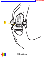
1
RETURN TO MAIN MENU
Tech 2 User’s Guide
CONTENTS
I. Introduction
II. Care & Cleaning
III. Getting Started
IV. Power Supply
V. Adapters
VI. Troubleshooting
VII. Software
©2005 GM Service and Parts Operations
RETURN TO MAIN MENU
Tech 2 User’s Guide
The Tech 2 User’s Guide provides a comprehensive overview of the Tech 2 scan tool.
Everything contained in this manual is based on the latest product information available at the time of
publication. The right is reserved to make changes at any time without notice.
No part of this publication may be reproduced, stored in any retrieval system, or transmitted in any form
by any means, including but not limited to electronic, mechanical, photocopying, recording, or otherwise,
without the prior written permission of GM Service and Parts Operations. This includes all text, tables,
illustrations, and charts.
Requests for permission should be sent to:
General Motors Corporation
Service and Parts Operations
Product Engineering
37350 Ecorse Road
Romulus, MI 48174-1376
U.S.A.
© 2005 GM Service and Parts Operations. Made in the U.S.A. All rights reserved.
® Tech 2 is a registered trademark of General Motors Corporation.
GM
Ser vice and Par ts Operations
2005
Tech 2 User’s Guide
i
RETURN TO MAIN MENU
Customer Support Overview
To obtain assistance with a question or problem concerning the operation of your Techline product and its
attached products, or to arrange for warranty and non-warranty repairs, telephone the GM-Techline
Customer Support Center. To order replacement parts, contact GM Dealer Equipment or your customer
support representative for GM-Techline.
Before Calling
Before making a call to the Customer Support Center or GM Dealer Equipment, be sure to have the
following information ready:
• Dealership name, address and dealer code number
• Serial number of equipment or tool
• Name, part number, and quantity of the item to be requested
• Telephone number where the technician may be reached
Prepare a brief description of the problem:
• Tell when the problem occurred
• List any error codes displayed
• Tell what accessories were being used when the problem occurred, and vehicle information
Please see next page...
2005
Tech 2 User’s Guide
ii
RETURN TO MAIN MENU
Making the Call
The GM Service and Parts Operations Techline Customer Support Center telephone lines operate from
8:00 a.m. to 8:00 p.m. (Eastern Standard Time) Monday to Friday.
In the United States and Canada to contact Customer Support, dial:
•
•
•
•
English: 1-800-828-6860 (option 1) or 1-888-337-1010 (option 3)
French: 1-800-503-3222
Spanish: 1-248-265-0840 (option 2)
Fax line: 1-248-265-9327*
To call GM Dealer Equipment, dial 1-800-GM-TOOLS (1-800-468-6657).
International customers can send questions or comments by fax, (U.S. country code) 248-265-9327, or
use the following telephone numbers:
Latin America 1-248-265-0840
Europe
41-41-766-2940
Asia Pacific 045-562-4483
Australia
613-9544-6222
A GM-Techline Customer Support representative will come on the line or respond by fax to answer
questions, make suggestions, and take repair and parts orders. To make sure every problem is resolved to
the satisfaction of the caller, the GM-Techline Customer Support representative will record each problem,
question, or suggestion into a special problem tracking system. Any problems that cannot be resolved over
the phone will be directed to the appropriate group for resolution.
* You may also send a GM-Techline Product Assistance fax form to the Customer Support Center.
2005
Tech 2 User’s Guide
iii
RETURN TO MAIN MENU
Declaration of Conformity
According to ISO/IEC Guide and EN 45014,
Manufacturer’s Name:
Vetronix Corp.
Manufacturer’s Address:
2030 Alameda Padre Serra
Santa Barbara, CA 93103
declares that the product,
Product Name:
Tech 2
Model Number(s):
Z1090A
Product Options:
ALL
conforms to the following product specifications:
Safety:
IEC 1010-1: 1990 + A1 / EN 61010-1: 1993
EMC:
CISPR 11: 1990 / EN 55011 1991 - Class A
EN 50082-1: 1992
IEC 801-2: 1991 / prEN 55024-2 1992 - 3kV CD, 8kV AD
IEC 801-3: 1984 / prEN 55024-3 1991 - 3V/m
IEC 801-4: 1988 / prEN 55024-4 1992 - 0.5kV
Signal Lines. 1kV Power Lines
Supplementary Information
This is a Class A product. In a domestic environment this product may cause radio interference in which
case the user may be required to take adequate measures.
The product herewith complies with the requirements of the Low Voltage Directive 73/23/EEC and the
EMC Directive 89/336/EEC.
Location:
Santa Barbara, California
Date:
3 / 19 / 01
QA Manager:
David Parker, Product Regulations
2005
Tech 2 User’s Guide
iv
RETURN TO MAIN MENU
Software License Agreement
Please read this license agreement carefully before proceeding to operate the equipment. Rights to the
software are offered only on the condition that the customer agrees to all terms and conditions of the
license agreement. Proceeding to operate the equipment indicates your acceptance of these terms and
conditions:
1. USE: Customer may use the software only on the computer system on which it was originally installed. Customer may not reverse
assemble or decompile software unless authorized by law.
2. OWNERSHIP: Customer agrees that it does not have any title or ownership of the software, other than ownership of the physical
media. Customer acknowledges and agrees that the software is copyrighted and protected under the copyright laws. Customer
acknowledges and agrees that the software may have been developed by a third party software supplier named in the copyright
notices included with the software, who shall be authorized to hold the Customer responsible for any copyright infringement or
violation of this agreement.
3. TERMINATION: General Motors may terminate this software license for failure to comply with any of these terms provided GM has
requested Customer to cure the failure and Customer has failed to do so within thirty (30) days of such notice.
Limited Warranty
SOFTWARE: Vetronix warrants for a period of ninety (90) days from the date of purchase that the Vetronix software product
will execute its programming instructions when properly installed. Vetronix does not warrant that the operations of the
Vetronix software will be uninterrupted or error free. In the event that this Vetronix software product fails to execute its
programming instructions during the warranty period, the remedy shall be a replacement of such software product.
LIMITATION OF WARRANTY: Vetronix makes no other express warranty, whether written or oral with respect to this product.
Any implied warranty of merchantability or fitness for or a particular purpose is limited to the 90-day duration of this written
warranty. Some states or provinces do not allow limitations on how long an implied warranty lasts, so the above limitations or
exclusion may not apply to you.
EXCLUSIVE REMEDIES: The remedies provided above are Customer’s sole and exclusive remedies. In no event shall
Vetronix be liable for any direct, indirect, special, incidental or consequential damages (including lost profit) whether based
on warranty, contract, tort or any other legal theory.
2005
Tech 2 User’s Guide
v
RETURN TO MAIN MENU
SECTION I
INTRODUCTION
Using This Manual
To increase their effectiveness with the Tech 2, users should familiarize themselves with the format and
information contained in this guide.
IMPORTANT
Tech 2 figures and illustrations are hyperlinked to the text of this manual. To view a figure, simply click
on its description, which is shown in blue text. After viewing the figure, click on the rainbow-colored
arrow at the lower left-hand corner of the screen to return to your place in the manual.
Vehicle System Familiarity
While the Tech 2 is a powerful tool, it cannot replace knowledge and skill. To obtain maximum benefit from
the Tech 2, service technicians must have a complete understanding of vehicle systems.
When using the Tech 2 to diagnose a vehicle, it is recommended that service technicians also refer to the
service manual and the latest service bulletins.
Disclaimer
The Tech 2 is designed for use by trained service personnel only. It has been developed for the sole
purpose of diagnosing and repairing automotive systems with electronic controls and interfaces.
Every attempt has been made to provide complete and accurate technical information based on factory
service information available at the time of publication. However, the right is reserved to make changes at
any time without notice.
2005
Tech 2 User’s Guide
I-1
RETURN TO MAIN MENU
SECTION I
INTRODUCTION
Things You Should Know
CAUTION: EXHAUST GAS
When performing any checks with the engine running in an enclosed space such as a garage, ensure proper
ventilation. Never inhale exhaust gases; they contain carbon monoxide—a colorless, odorless, extremely dangerous
gas that can cause unconsciousness or death.
CAUTION: PARKING BRAKE
To help avoid personal injury, always set the parking brake securely and block the drive wheels before performing
any checks or repairs on the vehicle.
CAUTION: SPARKS
The Tech 2 uses parts that can produce arcs or sparks. When used in a garage environment, the Tech 2 must be
located not less than 18 inches (460 mm) above the floor.
Please see next page...
2005
Tech 2 User’s Guide
I-2
RETURN TO MAIN MENU
SECTION I
INTRODUCTION
NOTICE
• DO NOT clasp battery clamps together when connected simultaneously to the vehicle’s 12 volt
cigarette lighter or power supply. Reverse polarity in the vehicle’s cigarette lighter may be present.
Damage could occur to the Tech 2 or to the vehicle.
• If power is applied to the Tech 2 and the display remains blank, reverse polarity in the cigarette
lighter may be present. Damage to the Tech 2 could occur. DO NOT connect the DLC cable to the
vehicle. Verify that the center contact of the vehicle’s cigarette lighter has +12 volts and that the outer
contact is grounded.
• Turn off the power before inserting or removing the PCMCIA card. Continual removal and reinsertion
of this card is not recommended.
• Align all cards and components carefully before inserting them into the Tech 2.
• Make sure all cables and adapters are firmly connected before starting to use the Tech 2.
• Always read the instructions completely before attempting a new procedure.
• The RS-232 and RS-485 ports must not be connected to a direct phone line as the Tech 2 was not
designed for this method of communication.
• Do not place the Tech 2 so that the tilt stand can make contact with the vehicle battery terminal as
this could short out the battery.
2005
Tech 2 User’s Guide
I-3
RETURN TO MAIN MENU
SECTION I
INTRODUCTION
FCC Compliance
This equipment has been tested and found to comply with the limits for a Class A digital device, pursuant
to Part 15 of the FCC rules. These limits are designed to provide reasonable protection against harmful
interference when the equipment is operated in a commercial environment.
This equipment generates, uses, and can radiate radio frequency energy. If not installed and used in
accordance with the instruction manual, it may cause harmful interference to radio communications.
Operation of this equipment in a residential area is likely to cause harmful interference’s in which case the
user will be required to correct the interference at his or her own expense.
VDE Certification (for European Use)
This equipment complies with the requirements of VDE 0871/6.78. Improper use or maintenance neglect
may cause unacceptable radio or TV interference.
2005
Tech 2 User’s Guide
I-4
RETURN TO MAIN MENU
SECTION I
INTRODUCTION
Tech 2 Overview
The Tech 2 is a hand-held computer designed to aid in diagnosis and repair of automotive systems with
electronic controls and interfaces.
Figure I-1
External features of the Tech 2 (front view)
Hardware
The Tech 2 has been designed as a rugged, shop-ready tool by having:
• A sturdy case
• A sealed keypad
• Heavy-duty cables and connectors
You can expect years of trouble-free service if you take reasonable care of the Tech 2 and follow the
maintenance procedures outlined in Section II.
Figure I-2
Table listing Tech 2 base kit part numbers and descriptions (see Section III for illustrations)
Figure I-3
Table listing part numbers for Tech 2 adapters and accessories (see Sections V and Section VII)
Video clip 1 (38 seconds)
90-degree adapter (J42598-20) installation demo*
*After viewing, click the X in the upper right-hand corner of the video window to close.
2005
Tech 2 User’s Guide
I-5
RETURN TO MAIN MENU
SECTION I
Power Supply
INTRODUCTION
(see Section IV)
The Tech 2 can be powered from:
• The automobile battery power cable
• The cigarette lighter power cable
• The Tech 2 power supply
• The DLC (Data Link Connector) connection in most vehicles
Figure I-4
Table listing part numbers for Tech 2 power supplies and cables (see Section IV)
Commands
The Tech 2 prompts you to enter commands via the membrane keypad for:
• Retrieving and viewing diagnostic information
• Selecting self tests
• Performing vehicle diagnostics
Data Storage
The Tech 2 contains electronic components called PCMCIA (Personal Computer Memory Card Industry
Association) cards, which store diagnostic programs. The Tech 2 can be updated as vehicle models
change by reprogramming the PCMCIA card via the RS-232 connector.
Figure I-5
Table showing the PCMCIA kit part number and description
2005
Tech 2 User’s Guide
I-6
RETURN TO MAIN MENU
SECTION I
INTRODUCTION
Mechanical Dimensions
The dimensions of the Tech 2 are as follows:
• Width – 6.1 inches (155 mm)
• Height – 11.8 inches (300 mm)
• Depth – 2.0 inches (55 mm)
• Weight – 2.2 pounds (1.0 kg)
Environmental Specifications
CONDITIONS
Temperature
Relative Humidity
SPECIFICATIONS
Operating:
0 to 40°C (32 to 104°F)
Non-operating:
-40 to 70°C (-40 to 158°F)
Operating:
15% to 95% at 40°C (non-condensing)
Non-operating:
90% at 65°C (non-condensing)
2005
Tech 2 User’s Guide
I-7
RETURN TO MAIN MENU
SECTION I
INTRODUCTION
Warranty
The Tech 2 is warranted against defects in materials and workmanship by the manufacturer for 24 months
beginning five days after the date of shipment to your service center.
If your Tech 2 must be sent in for repair, a replacement will be sent to your dealership prior to the return of
the failed Tech 2. Use the package that the replacement arrives in to return the defective unit. You can
contact Customer Support at 1-800-828-6860 for the exact exchange procedure. If notification of defect is
received during the warranty period, the part listed in figures I-2, I-3, I-4, or I-5 that is defective will be
replaced. You must return the defective unit as directed, or you will be charged for the replacement.
Important: This warranty does not cover any part that has been abused, altered, used for purpose other
than which it was intended, or used in a manner inconsistent with instructions regarding use. This
includes, but is not limited to, removal of any Tech 2 screws.
2005
Tech 2 User’s Guide
I-8
RETURN TO MAIN MENU
SECTION II
CARE & CLEANING
Care and Cleaning
After using the Tech 2, a few simple steps will insure that you get the most life out of this diagnostic tool.
NOTICE
Do not spray or pour cleaner anywhere on the Tech 2. If the Tech 2 should become dirty, clean it with a
mild detergent or hand soap. Avoid using harsh solvents such as petroleum-based cleaning agents:
acetone, benzene, trichlorethylene, etc. Harsh solvents can etch Tech 2 plastic surfaces.
Although the Tech 2 is water resistant it is not waterproof, so be sure to thoroughly dry off the Tech 2
prior to usage and/or storage.
Maintenance of the Tech 2 requires periodic inspection and cleaning of:
• The display window
• The keypad
• The cable assemblies and connectors
Make sure the Tech 2 is not connected to a vehicle or other power source and follow the cleaning
procedures detailed below.
Please see next page...
2005
Tech 2 User’s Guide
II - 1
RETURN TO MAIN MENU
SECTION II
CARE & CLEANING
Cleaning the Display
The display collects dust and grime during normal use. Occasionally wipe the screen with a clean, soft,
static-free cloth. Remove stubborn stains by applying a non-abrasive glass cleaner to a soft cloth and wipe
cloth across display area.
Cleaning the Keypad
Clean the keypad with a non-abrasive cleaner. Apply a small amount of cleaner on a soft cloth and wipe
cloth across keypad area.
Maintaining the Cable Assemblies and Connectors
Inspect cable assemblies during connection and disconnection to components. Watch for any cuts or
abrasions along the cables. Check the connectors and connector pins for grease, dirt and corrosion. If
contaminants are present, remove them with a mild soap solution.
Storing the Tech 2
• Store the Tech 2 away from solvents and other liquids. It is NOT moisture proof.
• Store the Tech 2 away from direct sunlight. Ultraviolet and infrared light will darken the display.
• Store the Tech 2 in its plastic case. Otherwise, the high-impact plastic cover could become scratched.
2005
Tech 2 User’s Guide
II - 2
RETURN TO MAIN MENU
SECTION III
GETTING STARTED
Getting Started
This section covers all Tech 2 vehicle applications. Therefore, some of the information provided may not
be required for individual applications.
The Tech 2 contains two serial communication ports: the RS-232 and the RS-485. Use the RS-232 port for
downloading data from another computer to the Tech 2. The RS-485 port is currently not used.
The Tech 2 also contains two PCMCIA ports, a power jack connector, and a Vehicle Communications
Interface (VCI) connector. One of the PCMCIA slots contains a memory card with diagnostic information.
The power jack accepts power from the AC/DC power supply, battery, or cigarette lighter power cable. The
VCI connector accepts the DLC cable or DLC loopback adapter.
Figure III-1
Identification of the Tech 2’s external ports
NOTICE
When using the Tech 2 for vehicle communications, the power jack must be connected to the Tech 2
DLC cable for proper grounding.
2005
Tech 2 User’s Guide
III - 1
RETURN TO MAIN MENU
SECTION III
GETTING STARTED
Initial Hardware Installation
The Tech 2 hardware initial installation requires the following seven tasks:
1. Remove the RS-232 loopback adapter (P/N 3000112) from the storage case (P/N 3000116). Plug it into
the RS-232 port (Figure III-2).
2. Attach the Tech 2 DLC cable (P/N 3000095) to the VCI connector (Figure III-3).
3. Locate the DLC loopback adapter (P/N 3000109) in the storage case. Attach it to the DLC cable
(Figure III-4).
4. Locate the NAO (P/N 3000113) or Universal (P/N 3000115) power supply and appropriate power cord in
the storage case. Insert the power jack into the Tech 2 DLC cable (Figure III-5) or into the bottom of the
Tech 2 next to DLC cable connector (Figure III-6).
5. Turn on power by pressing the PWR button located on the Tech 2 keypad.
6. Tech 2 hardware will be verified automatically by the POST test. (For information on this program, refer
to Section VI - Troubleshooting.)
7. Disconnect the RS-232 loopback adapter, the power supply, and the DLC loopback adapter and return
to the Tech 2 storage case (Figure III-7).
Figure III-2 – Connection of the RS-232
loopback adapter to the RS-232 port
Figure III-5 – Connection of the power jack
to the DLC cable
Figure III-3 – Connection of the DLC cable
to the VCI connector
Figure III-6 – Connection of the power jack
to the bottom of the Tech 2
Figure III-4 – Connection of the DLC
loopback adapter to the DLC cable
Figure III-7 – Disconnection of the RS-232
loopback adapter, DLC loopback adapter,
and the power supply
2005
Tech 2 User’s Guide
III - 2
RETURN TO MAIN MENU
SECTION III
GETTING STARTED
PCMCIA Card Removal
The PCMCIA Card is accessed by opening the hinged door located at the top of the Tech 2. The card is
found in the upper slot. The lower slot will be used for future enhancements. Press the arrow button
(located beside the slot) to eject the card (Figure III-8).
Figure III-8
Ejection of PCMCIA card
PCMCIA Card Insertion
The PCMCIA Card is keyed with two notches on one side and one notch on the other side (Figure III-9).
Make sure that the notches are in the correct position before inserting the card. Slowly insert the card
(Figure III-10) until it clicks into place.
Figure III-9
PCMCIA card keying
Figure III-10
PCMCIA card insertion
NOTICE
Use only GM Service and Parts Operations supplied PCMCIA cards. The PCMCIA slots are designed
to interface with 5-volt cards. Permanent damage to Tech 2 could occur if a 3.3-volt card is inserted into
the Tech 2 PCMCIA connector.
2005
Tech 2 User’s Guide
III - 3
RETURN TO MAIN MENU
SECTION III
GETTING STARTED
Vehicle Communications Interface Module Removal
The Vehicle Communications Interface (VCI) module is located at the lower end of the Tech 2. Removal of
this module is required only if the VCI needs to be updated or replaced.
To remove the module disconnect Tech 2 DLC cable if attached, move the lever (Figure III-11) all the way
toward the right side of the Tech 2 (Figure III-12). The VCI module can now be removed.
Figure III-11
VCI module removal
Figure III-12
VCI module removed
Hand Strap Adjustment
The Tech 2 velcro hand straps may be adjusted for individual needs as shown in the illustration below
(Figure III-13).
Figure III-13
Tech 2 hand strap adjustment
2005
Tech 2 User’s Guide
III - 4
RETURN TO MAIN MENU
SECTION III
GETTING STARTED
Tech 2 Keypad
The Tech 2 keypad consists of six major keypad operation areas (Figure III-14):
1.
2.
3.
4.
5.
6.
Control keys (SHIFT, PWR)
Soft keys
Selection (arrow) keys
Action keys (YES, NO, ENTER, EXIT)
Function keys (F0 to F9)
Help (?) key
Control Keys
The [PWR] key is used to turn the Tech 2 on or off (Figure III-15). The status indicator light above this key
will be illuminated green when the Tech 2 is operational.
The [SHIFT] key is used with the up and down arrow keys to change screen brightness and contrast
(Figure III-15). To adjust screen brightness and contrast, perform the following:
• Press the [SHIFT] key once (amber status indicator light above [SHIFT] should light up).
• Use up and down arrows to adjust screen brightness and contrast:
Press up arrow key to increase screen brightness and contrast.
Press down arrow key to decrease screen brightness and contrast.
• Press [SHIFT] key again when desired brightness is reached (status indicator light above [SHIFT]
should now be off).
The Tech 2 should return to normal operation after following the above steps.
Figure III-14
Tech 2 keypad
Figure III-15
Location of control keys
2005
Tech 2 User’s Guide
III - 5
RETURN TO MAIN MENU
SECTION III
GETTING STARTED
Soft Keys
Four soft keys are located directly below the Tech 2 screen (Figure III-16). The soft keys correspond
directly to the four possible selection boxes found at the bottom region of the Tech 2 screen. These
selections may change from screen to screen and are under the control of the application software. To
make a screen selection, press the corresponding soft key. In the example shown in Figure III-17, the first
soft key was pressed to select [Display Time].
Figure III-16
Location of soft keys
Figure III-17
Soft key selection for display time
Selection Keys
The Tech 2 selection keys are four directional arrow keys (Figure III-18). Press the arrow keys to move the
highlighted area to a selection on the screen (Figure III-19) or to scroll the screens if more than one. Once
the desired selection is highlighted, press [ENTER] to activate the selection.
Figure III-18
Location of selection keys
Figure III-19
Positioning the highlighted area to make a selection
2005
Tech 2 User’s Guide
III - 6
RETURN TO MAIN MENU
SECTION III
GETTING STARTED
Action Keys
Action keys are used to respond to a specific question, initiate an action, or to exit from the Tech 2
program (Figure III-20). Specific “yes or no” questions will often appear on the Tech 2 screen. The [YES]
and [NO] keys are used to respond to these questions. Either of the two [ENTER] keys may be pressed to
activate a menu selection. Either of the two [EXIT] keys may be pressed to leave the current Tech 2
screen and return to a previous screen.
Figure III-20
Location of action keys
Function Keys
Ten function keys (F0 to F9) are located on the Tech 2 keypad (Figure III-21). A function key may be
pressed to initiate a specific Tech 2 function. In some cases the function keys are used for numeric data
entry. The arrow keys and [ENTER] may also be used to initiate a function selection, but this will require
multiple keystrokes as opposed to only one.
Figure III-21
Location of function keys
Help Key
The help key [?] may be pressed at any time to obtain a help screen (Figure III-22). The help screen will
provide specific information relating to the operation of the Tech 2.
Figure III-22
Location of help key
2005
Tech 2 User’s Guide
III - 7
RETURN TO MAIN MENU
SECTION III
GETTING STARTED
Tech 2 Connection to Vehicle
The Tech 2 receives power through the DLC cable connection to vehicles equipped with On-Board
Diagnostics (OBD II) (Figure III-23). In the case of vehicles not equipped with OBD II, an external power
source such as a vehicle cigarette lighter must be used (Figure III-24).
Figure III-23
Attaching the Tech 2 to OBD II equipped vehicles
Figure III-24
Attaching the Tech 2 to non-OBD II equipped vehicles
2005
Tech 2 User’s Guide
III - 8
RETURN TO MAIN MENU
SECTION III
GETTING STARTED
Tech 2 Connection to Techline Terminal
At times the Tech 2 will need to be connected to a terminal. Reasons for connection to a terminal include
the following:
• Transfer of vehicle data (calibration information, “snapshot,” etc.) from the Tech 2 to the terminal
• Transfer of vehicle calibration data from the terminal to the Tech 2
• Transfer of data (software update, etc.) from the terminal to the Tech 2
Before connecting Tech 2 to the terminal, the following steps should be taken:
• Make sure the RS-232 cable (P/N 3000110) is attached to the Tech 2 RS-232 port located on the left
side of the Tech 2 (Figure III-1 and Figure V-3).
• Make sure the appropriate power supply is connected to the DLC cable power jack connector, or to the
power jack connector at the bottom of the Tech 2 (Figure III-25).
• Make sure the PCMCIA card is fully inserted into the upper slot at the top of the Tech 2 (Figure III-8,
Figure III-9 and Figure III-10).
• Make sure the CANdi module is not connected to the Tech 2.
Figure III-25
Power supply connections for communication with computer terminals
NOTICE
Always use the Tech 2 NAO power supply (P/N 3000113) when connecting the Tech 2 to a terminal. It is
also acceptable to connect the power cable to the vehicle cigarette lighter receptacle.
2005
Tech 2 User’s Guide
III - 9
RETURN TO MAIN MENU
SECTION III
GETTING STARTED
How to Connect the Tech 2 to a Computer Terminal
Follow the steps below and refer to Figure III-26, which illustrates the typical Tech 2 connection to a
computer terminal.
1. Plug the serial port adapter (P/N TA00040) into the serial port marked “A” or “1” on the back of the
computer terminal or to the USB port using the USB serial adapter.
2. Plug the Tech 2’s RS-232 cable into the serial port / USB port adapter and connect the appropriate
power supply.
3. After power is supplied to the Tech 2 and the [PWR] button is pressed, the Tech 2 start-up display
should appear on the Tech 2 screen (Figure III-27).
Figure III-26
Typical Tech 2 connection to a computer terminal (rear view)
Figure III-27
Tech 2 displaying the Tech 2 start-up screen
2005
Tech 2 User’s Guide
III - 10
RETURN TO MAIN MENU
SECTION IV
POWER SUPPLIES
Power Supplies
Power up the Tech 2 using either:
• The power jack connector at the bottom of the Tech 2 unit (Figure IV-1), or
• The DLC cable power jack connector behind the area where various DLC adapters are connected
(Figure IV-1).
For non-vehicle communications, connect power source to either location.
For vehicle communications, connect the power source to the DLC cable power jack connector only.
Proper grounding may not be present if power source is connected directly to Tech 2.
When the Tech 2 is connected to the DLC of an appropriate vehicle, the vehicle battery supplies power.
When the Tech 2 is not connected to the vehicle’s DLC, the DLC cable power jack connector accepts
power from the following:
• Cigarette lighter power cable (Figure IV-1, see text on page IV-2)
• Battery power cable (Figure IV-1, see text on page IV-2)
• NAO or Universal power supply (Figure IV-1 and Figure IV-2, see text on page IV-3)
If the DLC and external power source are both connected, the power jack connection supplies current to
the Tech 2. In this instance, power from the vehicle’s DLC connector is automatically disconnected from
the Tech 2 internal power supply.
Figure IV-1
Tech 2 power connections (without direct power connection from the DLC)
2005
Tech 2 User’s Guide
IV - 1
RETURN TO MAIN MENU
SECTION IV
POWER SUPPLIES
Cigarette Lighter Power Cable
This cable contains one fuse and two connectors. It has a cigarette lighter plug at one end and a power
jack at the other (Figure IV-1). The power jack connects to the Tech 2 DLC cable and carries power to the
Tech 2 when the selected vehicle adapter does not provide power.
Battery Power Cable
This cable has red and black battery clamps attached to one end and a power jack attached to the other
(Figure IV-1). The power jack connects to the Tech 2 DLC cable and carries current to the Tech 2 when the
selected vehicle adapter does not provide power and there is no cigarette lighter adapter available.
Important: This cable contains two 3-amp fuses. If you need to replace them, use identical 3-amp fuses.
For information on fuse replacement, see Section VI - Troubleshooting.
2005
Tech 2 User’s Guide
IV - 2
RETURN TO MAIN MENU
SECTION IV
POWER SUPPLIES
NAO Power Supply
North American electrical supply is normally 110 volts. The Tech 2 base kit includes an external AC to DC
power supply with 110 V AC/60 Hz input (Figure IV-2). Output is 12 volts at 1.5 amps.
Universal Power Supply
Wherever 220 current is required, use the 110/220 V AC/50 Hz external AC to DC power supply
(Figure IV-2). A specific power cord is provided to permit connection to your area’s power cord receptacle.
Figure IV-2
Tech 2 power supplies (NAO and Universal)
CAUTION
To avoid personal injury due to electric shock, use grounded outlet only. The NAO power supply
is for North American use only. The Universal power supply is for use outside North America.
These devices are intended for indoor use only.
Power Cord Plugs
Various types of power cord plugs are available for the Tech 2, depending your geographic location
(Figure IV-3).
Figure IV-3
Table showing various types of power cord plugs for the Tech 2
2005
Tech 2 User’s Guide
IV - 3
RETURN TO MAIN MENU
SECTION V
ADAPTERS
Adapters
A number of adapters are available for the Tech 2 which allow connection to many different vehicles
(Figure V-1 and Figure V-2). Specific adapters are included in the Tech 2 base kit depending upon Tech 2
configuration—NAO, International, Saab, Opel, Vauxhall, etc. Adapters not included in the base kit may be
purchased separately from your tool distributor.
DLC Cable
The DLC cable (P/N 3000095) has a 26-pin connector with thumb screws at one end that connects to the
Tech 2’s VCI cable connector. At the other end is a 19-pin connector that connects to a variety of adapters
(Figure V-1 and Figure V-2).
Figure V-1
DLC cable adapter connections
Figure V-2
Table showing various adapters and their part numbers
RS-232 Cable
The RS-232 cable (P/N 3000110) has an 8-pin RJ45 plug connector at each end (Figure V-3). This cable
attaches to the Tech 2 RS-232 port and is used to communicate with the Techline terminal.
Figure V-3
RS-232 cable connections
2005
Tech 2 User’s Guide
V-1
RETURN TO MAIN MENU
SECTION V
ADAPTERS
RS-232 DB9 Adapter
The RS-232 DB9 adapter (P/N 3000111) has an RJ45 connector at one end and a DB9 connector at the
other (Figure V-4). This adapter allows the connection of the Tech 2 to some terminals.
Figure V-4
RS-232 DB9 adapter connections
RS-232 Loopback Adapter
The loopback adapter (P/N 3000112) has an 8-pin RJ45 connector that attaches to the Tech 2 RS-232
port (Figure III-2). It is used to perform the Tech 2 self test.
DLC Loopback Adapter
Various Tech 2 applications require the DLC loopback adapter (P/N 3000109), which has a Burndy cable
connection end and a VCI DB-26 connection end (Figure V-5). Refer to pages III-1, III-2, VI-18, VII-69, and
figures I-2, III-4, III-7, and VI-4 for more information about this adapter.
Figure V-5
End views of the DLC loopback adapter
2005
Tech 2 User’s Guide
V-2
RETURN TO MAIN MENU
SECTION VI
TROUBLESHOOTING
Troubleshooting
Section VI is a general troubleshooting guide for all vehicle applications of the Tech 2 scan tool. Some of
the information may differ for your particular vehicle application.
If the Tech 2 appears to be operating abnormally, refer to this section—particularly the diagnostic charts
and troubleshooting tables beginning on page VI-6—for probable causes and solutions.
The following two types of self tests are available on the Tech 2:
• Power On Self Test (POST) checks the major functions of the Tech 2 at power-up.
• Self Tests check the major and minor functions of the Tech 2.
If errors are detected, a Tech 2 malfunction is present which may result in vehicle misdiagnosis.
For customer support, refer to the Customer Support Overview on pages ii and iii of this user’s guide.
NOTICE
The CANdi module should not be connected while running Tech 2 and VCI self tests.
2005
Tech 2 User’s Guide
VI - 1
RETURN TO MAIN MENU
SECTION VI
TROUBLESHOOTING
Power On Self Test (POST)
Power On Self Tests run automatically each time the power [PWR] button on the Tech 2 keypad is pressed
on. The screen displays pass or fail results for each area tested. POST automatically checks the following:
•
•
•
•
•
•
•
•
•
MC68332 processor
External RAM (Random Access Memory)
Flash memory
Display controller and display
Sound transducer
MC68332 RAM
Real-time clock
Keypad controller and keypad
Main UART (Universal Asynchronous Receiver/Transmitter)
Results of POST may include fatal errors that do not allow you to continue, or non-fatal errors that allow
you to continue without full Tech 2 operation. If normal Tech 2 functions are stopped or limited, contact
Customer Support to determine if service is required.
At completion of POST, the following audible signals indicate a pass or fail condition:
• One beep - No problem. Your Tech 2 is operating normally.
• No beep - Sound transducer has failed. Contact Customer Support.
• Three short beeps - Tech 2 has failed POST. Contact Customer Support.
In the United States and Canada to contact Customer Support, dial:
•
•
•
•
English:
French:
Spanish:
Fax line:
1-800-828-6860 (option 1)
1-800-503-3222
1-248-265-0840 (option 2)
1-248-265-9327
Refer to page iii for international customer support.
2005
Tech 2 User’s Guide
VI - 2
RETURN TO MAIN MENU
SECTION VI
TROUBLESHOOTING
Tech 2 Self Tests
Tech 2 self tests verify that the Tech 2 is functioning normally. The self tests evaluate all critical areas of
the Tech 2 and display pass or fail messages for each subsystem tested. Self tests isolate user error from
system hardware failures. The self tests should be performed periodically to insure that the Tech 2 is
operating properly.
The Tech 2 must meet the following requirements in order to do a self test:
• Screen display must be fully readable
• Keypad must be operational
Begin the Tech 2 self-testing program by following these steps:
1. Press [ENTER] while viewing the Tech 2 start-up screen (Figure VI-1).
2. Select F3: Tool Options from the Tech 2 Main Menu (Figure VI-2).
3. Select F3: Self Test from the Tool Options menu (Figure VI-3).
Figure VI-1
Tech 2 startup screen
Figure VI-2
Tools Options selected on Main Menu
Figure VI-3
Self Test selected on Tool Options menu
2005
Tech 2 User’s Guide
VI - 3
RETURN TO MAIN MENU
SECTION VI
TROUBLESHOOTING
Tech 2 Self Test Main Menu
Each Tech 2 Self Test main menu selection is explained in detail on the following pages. All users have
access to all the options listed, which are shown in Figure VI-5.
Read all screen instructions and connect or disconnect the appropriate cables and loopback adapters.
Screen messages will be displayed when external loopback connectors are connected. For specific
loopback connection information, refer to Figure III-2, Figure III-4, and Figure VI-4.
F0: Automated Main PCB and VCI Test
Selecting Automated Main PCB and VCI (Figure VI-5) is a quick way to test the performance of the main
Printed Circuit Board (main PCB—the Tech 2 main circuit board) and the Vehicle Communications
Interface (VCI). The Tech 2 displays a test-in-progress screen (Figure VI-6) while performing all the PCB
and VCI tests in sequential order.
Figure VI-4
Connection of DLC loopback adapter to the Tech 2 VCI connector
Figure VI-5
Automated Main PCB and VCI test selected on Tech 2 Self Test main menu
Figure VI-6
Automated Main PCB and VCI test results screen
Continued on next page...
2005
Tech 2 User’s Guide
VI - 4
RETURN TO MAIN MENU
SECTION VI
TROUBLESHOOTING
The Automated Main PCB portion tests the following components:
•
•
•
•
•
•
•
•
•
RAM / ROM
RS-485 loopback (This test requires the connection of a loopback adapter to the Tech 2.)
RS-232 loopback (This test requires the connection of a loopback adapter to the Tech 2.)
Keypad
PCMCIA slot 1
PCMCIA slot 2
Display controller
Sound transducer
Real-time clock
Refer to figures VI-9 and VI-10 (next page) for help in diagnosing problems that involve the PCB and VCI.
If the Tech 2 passes all Automated Main PCB and VCI tests, you will not need to run any more tests to
verify that the Tech 2 is working properly.
The following test results will be displayed:
Total Pass ................................ 1 - indicates that Tech 2 passed test
0 - indicates a test failure
Total Failures ........................... 0 - indicates that Tech 2 passed test
1 - indicates a test failure
PCMCIA Cards Present ........... 1 or 2 indicates how many cards present in Tech 2
Once tests are complete, select the soft keys Main Details or VCI Details (Figure VI-6) to review the
results of the main PCB or VCI tests (Figure VI-7 and Figure VI-8).
If any failures occur, select F3: Selectable Main PCB (Figure VI-13) or F4: Selectable VCI (Figure VI-15)
from the Self Test main menu to further isolate the failure. Report failure information to Customer Support.
2005
Tech 2 User’s Guide
VI - 5
RETURN TO MAIN MENU
SECTION VI
TROUBLESHOOTING
F1: Automated Main PCB Test
This test works the same as the Automated Main PCB and VCI test, except the VCI portion of the test is
not included (Figure VI-11).
F2: Automated VCI Test
This test works the same as the Automated Main PCB and VCI test, except the PCB portion of the test is
not included (Figure VI-12).
Figure VI-7
Main Details selection
Figure VI-8
VCI Details selection
Figure VI-9
Diagnostic chart for Tech 2 Main Printed Circuit Board (PCB)
Figure VI-10
Diagnostic chart for Tech 2 Vehicle Communications Interface (VCI) module
Figure VI-11
Automated Main PCB test selected on Tech 2 Self Test main menu
Figure VI-12
Automated VCI test selected on Tech 2 Self Test main menu
2005
Tech 2 User’s Guide
VI - 6
RETURN TO MAIN MENU
SECTION VI
TROUBLESHOOTING
F3: Selectable Main PCB Test
Choose F3: Selectable Main PCB (Figure VI-13) after a fail message has been displayed during the
Automated Main PCB and VCI or Automated Main PCB tests. When you choose F3: Selectable Main
PCB, a screen like the one shown in Figure VI-14 is displayed. You may then select individual tests for
failed components. For specific information on failed components, refer to the Main Printed Circuit Board
(PCB) Diagnostic Chart (Figure VI-9).
Figure VI-13
Selectable Main PCB test selected on Tech 2 Self Test main menu
Figure VI-14
Selectable Main PCB Self Test screen
2005
Tech 2 User’s Guide
VI - 7
RETURN TO MAIN MENU
SECTION VI
TROUBLESHOOTING
F4: Selectable VCI Test
Choose F4: Selectable VCI (Figure VI-15) after a fail message has been displayed during the Automated
Main PCB and VCI or Automated VCI tests. When you choose F4: Selectable VCI, a screen like the one
shown in Figure VI-16 is displayed. You may select individual tests for failed components from this screen.
If you select More Tests, a screen like the one shown in Figure VI-17 is displayed. If you then select
Previous Menu, the screen shown in Figure VI-16 returns. For specific information on failed components,
refer to the Vehicle Communications Interface (VCI) Module Diagnostic Chart (Figure VI-10).
F5: Power On Self Test Results
Choose F5: Power On Self Test Results (Figure VI-18) after a fail message has been displayed during the
Power On Self Test (POST). Specific information on the failure will be displayed on the screen. Select F0,
F1, F2, F3, or F4 to further isolate the specific fault.
Figure VI-15
Selectable VCI test selected on Tech 2 Self Test main menu
Figure VI-16
First selectable VCI Self Test screen
Figure VI-17
Second selectable VCI Self Test screen
Figure VI-18
Power On Self Test Results selected on Tech 2 Self Test main menu
2005
Tech 2 User’s Guide
VI - 8
RETURN TO MAIN MENU
SECTION VI
TROUBLESHOOTING
No Power to Tech 2 Troubleshooting Tables
Use the following four tables—Figure VI-19, Figure VI-20, Figure VI-21, and Figure VI-22—to diagnose,
isolate, and correct power source problems that may cause a No Power condition to your Tech 2 scan tool.
To help determine power supply source, see Section IV - Power Supplies.
Figure VI-19
Troubleshooting table for DLC cable “No Power”
Figure VI-20
Troubleshooting table for cigarette lighter power cable “No Power”
Figure VI-21
Troubleshooting table for battery power cable “No Power”
Figure VI-22
Troubleshooting table for NAO or universal power supply “No Power”
2005
Tech 2 User’s Guide
VI - 9
RETURN TO MAIN MENU
SECTION VI
TROUBLESHOOTING
Cigarette Lighter Power Cable 3-Amp Fuse Replacement
A three-amp removable fuse is located in the cigarette lighter power cable (P/N 3000096) connector
(Figure VI-23). When required, check or replace the fuse by performing the following steps:
1. Ensure cigarette lighter power cable is not connected to vehicle or Tech 2.
2. Unscrew fuse retainer cap and remove three-amp fuse.
3. Inspect fuse for damage and replace with identical three-amp fuse if required.
4. Verify by connecting cigarette lighter power cable to Tech 2 and vehicle.
Figure VI-23
Cigarette lighter power cable three-amp fuse replacement
2005
Tech 2 User’s Guide
VI - 10
RETURN TO MAIN MENU
SECTION VI
TROUBLESHOOTING
Battery Power Cable 3-Amp Fuse Replacement
Two three-amp fuses are located in the battery power cable (P/N 3000097) three-amp fuse box
(Figure VI-24). When required, check or replace the fuse(s) by performing the following steps:
1. Ensure battery power cable is not connected to vehicle battery or Tech 2.
2. Use a standard fuse puller to remove the fuse(s) from the fuse box.
3. Inspect fuse(s) for damage and replace with identical 3-amp fuse(s) if required.
4. Verify by connecting battery power cable to Tech 2 and vehicle battery.
Figure VI-24
Battery power cable three-amp fuse replacement
CAUTION:
To help avoid personal injury by electric shock, make sure the battery power cable is not
connected to the vehicle’s battery before removing the fuse(s).
2005
Tech 2 User’s Guide
VI - 11
RETURN TO MAIN MENU
SECTION VI
TROUBLESHOOTING
CANdi Module Troubleshooting
The following troubleshooting information applies only to the CANdi module. This application is
unavailable for most vehicles at the time of writing.
Figure VI-25 shows the screen that the Tech 2 displays during programming of the CANdi module.
If the Tech 2 loses power during programming, the CANdi module will not be properly programmed. The
CANdi module will be automatically reprogrammed when power is available.
Figure VI-25
CANdi module programming screen
If a fault occurs during reprogramming, a screen like the one shown in Figure VI-26 may appear. If this
occurs, power off the Tech 2 and attempt to reprogram the CANdi module again. If the problem persists,
incorrect CANdi software may be present on the Tech 2 PCMCIA card. Connect the Tech 2 to the TIS
terminal and download a new version of the software.
Figure VI-26
CANdi fault screen
NOTE: Do not perform a VCI self-test while the CANdi module is connected. If the CANdi module is
connected and an error screen occurs, disconnect the CANdi module from the Tech 2 and
perform the test again.
Continued on next page...
2005
Tech 2 User’s Guide
VI - 12
RETURN TO MAIN MENU
SECTION VI
TROUBLESHOOTING
The screen shown in Figure VI-27 is displayed when the Tech 2 does not detect the CANdi module. This
can occur under the following conditions:
• The CANdi module is not connected to the Tech 2, or
• A problem occurred during start-up that prevented the Tech 2 from configuring the CANdi module.
If this occurs, power the Tech 2 off and start again. If the problem persists, follow the troubleshooting tests
on page VI-15.
It is also possible to connect a CANdi module after the Tech 2 has been powered up via the VCI. If this
occurs, the Tech 2 will not detect CANdi module and will not properly communicate, even if the LED is
flashing on the CANdi module. Power off the Tech 2 and start again.
Figure VI-27
CANdi module not detected screen
The screen displayed in Figure VI-28 occurs when the Tech 2 loses communication with the CANdi
module. This could be a result of the following:
•
•
•
•
VCI not properly seated in the Tech 2 slot
DLC cable not properly connected
Poor Burndy cable connection to the CANdi module
Worn or damaged cable that results in a poor connection between the CANdi module and the VCI
If this occurs, check all Tech 2 and CANdi module connections, power off the Tech 2 and start again.
If problem persists perform the troubleshooting tests on page VI-15.
Figure VI-28
Tech 2 lost communication with the CANdi module screen
2005
Tech 2 User’s Guide
VI - 13
RETURN TO MAIN MENU
SECTION VI
TROUBLESHOOTING
CANdi Module Diagnostics
Select “CANdi Diagnostics” from the Tech 2’s Tools Options menu (Figure VI-29), and the screen shown in
Figure VI-30 appears. If the CANdi module is not connected, the screen shown in Figure VI-27 appears.
Figure VI-29
CANdi Diagnostics selected on Tool Options menu
Figure VI-30
CANdi Diagnostics menu: “POST Results” or “Self Test”
When you select “POST Results” from the CANdi Diagnostics menu (Figure VI-30), the screen shown in
Figure VI-31 appears. You can use the information to determine if the CANdi module had any problems
during its start-up sequence. Software and hardware revision numbers are identified and displayed.
Figure VI-31
CANdi POST Results screen
Selecting “Self Test” from the CANdi Diagnostics menu (Figure VI-30) initiates a complete test of the
CANdi module. When testing is complete, all results are displayed on the screen shown in Figure VI-32.
Figure VI-32
CANdi Self Test Results screen
2005
Tech 2 User’s Guide
VI - 14
RETURN TO MAIN MENU
SECTION VI
TROUBLESHOOTING
CANdi Module Troubleshooting Guide
If a CANdi module is not functioning properly, please perform the following tests:
1. Make sure the CANdi module is properly grounded by connecting to a vehicle or by using the 12-pin
ALDL connector, which has the signal and chassis ground shorted.
IMPORTANT
If not properly grounded, the CANdi module will appear to be defective when it is not. The CANdi
module will fail due to improper grounding if you use the 16-pin DLC (J-1962) connector and power the
Tech 2 from an AC/DC power supply. The adapter you use must have a GM part number. Although PVI
adapters are similar to GM adapters, they will not work with the CANdi module.
2. Verify that the Tech 2 passes all stand-alone self-tests. Replace the Tech 2 if it fails. If the Tech 2
passes, proceed to step three. The CANdi module must be disconnected to run self-tests. If the
CANdi module is connected, a message will appear instructing you to disconnect the module.
3. Verify that the VCI passes self-tests. Replace the VCI if it fails. If the VCI passes, proceed to step four.
The CANdi module must be disconnected to run self-tests. If the CANdi module is connected, a
message will appear instructing you to disconnect the module.
When performing this test, you must also perform the Selectable VCI test (option F4 on the self-test
menu—see Figure VI-15). First install the Burndy loopback adapter into the VCI 26-pin connector,
which does not require the cable. Once you select “Selectable VCI,” select the “More Tests” soft key
(Figure VI-16). In the new submenu, select “F6: VCI TPU” (Figure VI-17). If the VCI passes the test, all
the TPU channels will display a Pass indicator as shown in the example at the top of the next page.
Continued on next page...
2005
Tech 2 User’s Guide
VI - 15
RETURN TO MAIN MENU
SECTION VI
TROUBLESHOOTING
Testing
Status
TPU0
TPU1
TPU5
TPU12 and 15
TPU13 and 14
Pass
Pass
Pass
Pass
Pass
The two TPU inputs that the CANdi module requires are TPU12 and TPU15, which enable the module
and detect its presence. If TPU12 and 15 do not appear on the screen, then they are defective in the
VCI module and the VCI is failing to properly enable the CANdi module. If the above test passes, you
must repeat the same test with the Burndy loopback adapter at the end of the cable. The setup is the
same as if you were plugging into a vehicle without the CANdi module connected and with the loopback
adapter at the end of the cable. Then you must run the VCI TPU test. If the example above appears
(TPU13 and 14 are missing in this test because these I/Os don’t go through the cable), then the cable
is also fine. However, if TPU12 and 15 are missing, then the cable is defective.
4. Verify that the DLC cable (also known as the ALDL, J-1962, or OBDII interface cable) is functioning
properly and then proceed to step five. Replace the DLC cable if it does not function properly. Call the
Techline Customer Support Center (TCSC) at 1-800-828-6860 for more information if you have trouble
with this test.
Continued on next page...
2005
Tech 2 User’s Guide
VI - 16
RETURN TO MAIN MENU
SECTION VI
TROUBLESHOOTING
5. Connect the CANdi module to the Tech 2. Connect the system (Tech 2 and CANdi module) to a vehicle
and power on the Tech 2. Verify that the LED on the CANdi module is flashing.
If the LED does not flash or light up at all, it may be defective and you should proceed to step six.
If the LED is not flashing but illuminated, a bad ground may exist somewhere. The grounding problem
could be due to a defective ALDL (J-1962) female interface on the vehicle. Power the Tech 2 through an
AC/DC power supply and connect the 12-pin ALDL connector. If this fixes the problem with the CANdi
(the LED is flashing), then the vehicle has a grounding problem and the CANdi module is OK.
If the LED is flashing while connected to the vehicle, but the CANdi module still has a problem, proceed
to step six.
6. If problems persist with the CANdi module, and the Tech 2 recognizes the interface, perform self-test
diagnostics on the CANdi module. Select CANdi Diagnostics from the Tool Options menu (Figure VI-29)
to see the CANdi Diagnostics menu (Figure VI-30). This menu allows you to display POST results, or
request the CANdi module to perform a self-test. Refer to page VI-14 for more information.
If a diagnostic test fails, return the CANdi module to the repair center (see page VI-18).
Contact the Customer Support Center at 1-800-828-6860 before returning the CANdi module.
If a known problem with a software version is identified, Customer Support will inform you to update
Tech 2 software with the correct software version number.
2005
Tech 2 User’s Guide
VI - 17
RETURN TO MAIN MENU
SECTION VI
TROUBLESHOOTING
Replacing the CANdi Module
If CANdi fails and Customer Support (800-828-6860) has verified that it needs to be replaced, package the
CANdi module and send it freight prepaid to the nearest Vetronix Warranty Repair Center, as listed below.
Vetronix Warranty Repair Centers:
United States and Latin America
Vetronix Corporation
2030 Alameda Padre Serra
Santa Barbara, CA 93103
U.S.A. - (805) 966-2000, Fax (805) 966-3845
Canada
Custone Electromotive Inc.
1150 Champlain Court
Whitby, ON L2N 6A8
Canada
Europe
Getronics Service GmbH/Frankfort
Philipp-Reis Strasse 15
D-63128 Dietzenback
Germany
Please enclose your telephone number, return address, and an explanation of the problem. If the product
is determined to be in warranty, it will be repaired or replaced at no charge and returned freight prepaid.
If determined to be non-warranty, the product will be repaired for a nominal service fee, plus freight costs.
Part numbers - CANdi module: J-45289 (SPX), 3000164 (GM), 02003039 (Vetronix)
Connectors: 12-pin #3000099 and loop back #3000109
2005
Tech 2 User’s Guide
VI - 18
RETURN TO MAIN MENU
SECTION VI
TROUBLESHOOTING
Additional CANdi Troubleshooting Tips
Transformer voltage output test using DVOM:
• Set DVOM to Volt setting.
• Probe cable end inside and outside the terminal.
• Twelve volts is the minimum.
Updating the CANdi module:
IMPORTANT
You must use a 32-megabyte (32-MB) PCMCIA card in the Tech 2, not a 10-megabyte (10-MB) card.
You must update the 32-MB PCMCIA card before connecting the CANdi module to the Tech 2.
Always disconnect the CANdi module from the Tech 2 before downloading software updates to
the PCMCIA card.
The CANdi module is capable of storing up to three different software versions.
• Will the CANdi module require updates?
Possibly. The CANdi module ships complete with software, but possibly not the most current version.
• Be sure to update the Tech 2 with the latest software before using the CANdi module.
The CANdi module will compare software and look for a possible update from the Tech 2. When you
update the Tech 2, any software updates for the CANdi module will download to the PCMCIA card.
The CANdi module will automatically receive updates each time it is connected to the DLC and Tech 2 at
power-up. Therefore, it is very important that you always run the latest available software version when
using the CANdi module.
2005
Tech 2 User’s Guide
VI - 19
RETURN TO MAIN MENU
SECTION VII
SOFTWARE
Software
Section VII contains a description of software related to the Tech 2 in four subsections:
A)
B)
C)
D)
Tech 2 Main Menu and Live Plot, beginning on page VII-2
Techline Information System (TIS), beginning on page VII-14
Service Programming System (SPS), beginning on page VII-36
Controller Area Network Diagnostic Interface (CANdi), beginning on page VII-67
IMPORTANT
Proper PCMCIA updates are required and are essential for successful vehicle diagnoses. Refer to the
Programming Tech 2 function under Tool Options, and the Tech 2 PCMCIA Card in the Techline
Information System (TIS) subsection.
2005
Tech 2 User’s Guide
VII - 1
RETURN TO MAIN MENU
SECTION VIIA
TECH 2 MAIN MENU & LIVE PLOT
Tech 2 Main Menu
Five primary functions or “paths” are available on the Tech 2’s Main Menu:
Diagnostics, Service Programming System, View Captured Data, Tool Options, and Getting Started are all
described in more detail on the following pages.
Figure VIIA-1
Tech 2 Main Menu
2005
Tech 2 User’s Guide
VII - 2
RETURN TO MAIN MENU
SECTION VIIA
TECH 2 MAIN MENU & LIVE PLOT
Diagnostics
Selecting Diagnostics from the Tech 2 Main Menu and identifying the vehicle as shown below gives you
access to four major systems: Powertrain, Body, Chassis, and Diagnostic Circuit Check (Figure VIIA-2).
F0: DIAGNOSTICS
Vehicle Identification:
Select Model Year
1991-2003
Select Vehicle Type
Passenger Car
LD Trk, MPV, Incomplete
Medium Duty Truck, Saturn
Select System
F0:
F1:
F2:
F3:
Powertrain
Body
Chassis
Diagnostic Circuit Check
Figure VIIA-2
System Selection Menu
2005
Tech 2 User’s Guide
VII - 3
RETURN TO MAIN MENU
SECTION VIIA
TECH 2 MAIN MENU & LIVE PLOT
Service Programming System
Selecting Service Programming System from the Tech 2 Main Menu leads to selections shown below.
Refer also to Section VIIC.
F1: SERVICE PROGRAMMING
(for remote programming only)
Request Info.
Continue (soft key) with Instructions
Vehicle Identification:
Salesmake(s)
Model Year(s)
Vehicle Type(s)
Model (body, style)
Continue (soft key) with Instructions
VIN Verification (Y/N)
Procedural Instructions Screen
View Captured Data
Selecting View Captured Data from the Tech 2 Main Menu results in the selections shown below.
F2: VIEW CAPTURED DATA
Capture Info
Snapshot
Select Items, Plot, Select Frame, Auto Reverse, Stop, Auto Forward
First Frame, Trigger Frame, Last Frame, Units, Previous Frame,
Next Frame DTC, Previous DTC-Chg, Next DTC-Chg
Live Plot - Change Min/Max, Zoom In-Out
F0: DTC Information
F1: Freeze Frame / Failure Records
2005
Tech 2 User’s Guide
VII - 4
RETURN TO MAIN MENU
SECTION VIIA
TECH 2 MAIN MENU & LIVE PLOT
Tool Options
Selecting Tool Options from the Tech 2 Main Menu (see Figure VI-2) gives you the Tool Options menu
(Figure VIIA-3), leading to 10 major selections, as follows:
F3: TOOL OPTIONS
↓
F0: Set Clock
F1: Set Screen Contrast
F2: Set Units
(Metric or English)
F3: Self Test
F4: Set Training Center Mode
(Instructor or Student)
F5: Programming Tech 2
F6: Set Communication By-Pass Mode
F7: Make Duplicate PCMCIA Card
F8: Set Language
F9: CANdi Diagnostics
These features—described in more detail on the following pages—are useful for controlling various Tech 2
settings including the self tests and CANdi diagnostics.
Figure VIIA-3
Tool Options menu
Tool Options continued on next page...
2005
Tech 2 User’s Guide
VII - 5
RETURN TO MAIN MENU
SECTION VIIA
TECH 2 MAIN MENU & LIVE PLOT
F0: Set Clock
After you select F0: Set Clock from the Tool Options menu (Figure VIIA-3) and the Set Real-Time Clock
menu (Figure VIIA-4) appears, you can set the internal Tech 2 real-time clock in two ways:
1. Use the up and down arrow keys to move the cursor to desired selection. Press [ENTER] to change the
value. Each time [ENTER] is pressed the value will be increased by one unit until a preset maximum
unit is reached. Once all correct values are entered, press the Set Clock soft key to save all changes.
2. Use the function key of the desired selection to change an incorrect value. Each time the function key is
pressed the value will be increased by one unit until a preset maximum is reached. Once all correct
values are entered, press the Set Clock soft key to save all changes.
Figure VIIA-4
Set Real-Time Clock menu
Tool Options continued on next page...
2005
Tech 2 User’s Guide
VII - 6
RETURN TO MAIN MENU
SECTION VIIA
TECH 2 MAIN MENU & LIVE PLOT
F1: Set Screen Contrast
Selecting F1: Set Screen Contrast reveals a Set Contrast Control screen (Figure VIIA-5) that instructs
you on how to set and save the screen contrast to optimize the tool’s visibility in your lighting conditions.
IMPORTANT
The Set Contrast Control tool option adjusts the permanent default contrast setting of Tech 2 display.
Because of the nature of the LCD (Liquid Crystal Display), you will experience some contrast variance.
When the temperature of the Tech 2 increases the display will brighten slightly. As the temperature of the
Tech 2 decreases, the display will darken. This variance is a characteristic of an LCD screen and should
be considered normal operation.
The screen contrast control setting described above may not account for the entire variance of operating
temperatures. Set a default setting which is mid-range between the operating temperatures. Screen
contrast may be adjusted during any function by pressing the SHIFT key and using the up and down
arrows for adjustment. Periodic adjustments may be necessary, but settings outside of this application are
only retained during the current power-up session.
Figure VIIA-5
Set Contrast Control screen
Tool Options continued on next page...
2005
Tech 2 User’s Guide
VII - 7
RETURN TO MAIN MENU
SECTION VIIA
TECH 2 MAIN MENU & LIVE PLOT
F2: Set Units
When you select the F2: Set Units option, a Set Units screen will appear (Figure VIIA-6). Use the up and
down arrow keys to change the Current Units Setting from English to Metric or vice versa, if desired. Press
[ENTER] to save your setting as the default.
Figure VIIA-6
Set Units screen
F3: Self Test
Selecting F3: Self Test gives you access to the Tech 2 Self Test menu screen (Figure VI-5), which will help
you to verify that the Tech 2 is functioning normally. Refer to Section VI - Troubleshooting for more
information on this area.
Power Down Screen. After completion of any Self Test, return to the Tech 2 Self Test menu screen. After
pressing [EXIT], a screen will appear instructing you to turn the Tech 2 power off (Figure VIIA-7). Turn off
the Tech 2 and turn back on to continue.
Figure VIIA-7
Tech 2 power down screen
Tool Options continued on next page...
2005
Tech 2 User’s Guide
VII - 8
RETURN TO MAIN MENU
SECTION VIIA
TECH 2 MAIN MENU & LIVE PLOT
F4: Set Training Center Mode
After you select F4: Set Training Center Mode—for GM Training Centers only—a Set Training Center
Mode screen appears (Figure VIIA-8), giving you the ability to connect multiple Tech 2 scan tools for
instructional purposes.
Figure VIIA-8
Set Training Center Mode screen
F5: Programming Tech 2
After you select F5: Programming Tech 2, you can follow the on-screen instructions (Figure VIIA-9) for
downloading from a PC to the Tech 2 scan tool via the RS-232 cable. Refer also to Software Download,
Tech 2 PCMCIA Card, and Tech 2 Update Procedure later in this section.
Figure VIIA-9
Programming Tech 2 screen
F6: Set Communication By-Pass Mode
When you select F6: Set Communication By-Pass Mode, the upcoming screen (Figure VIIA-10) offers
Disable and Enable options. By enabling the by-pass mode, the Tech 2 bypasses error handling and
allows the user to view data display information without being connected to a vehicle. Highlight the desired
setting using the up or down arrow keys, then press [ENTER] to change the current mode. The Tech 2 will
default to the Disable mode after it has been powered off.
Figure VIIA-10
Set Communication By-Pass Mode screen
Tool Options continued on next page...
2005
Tech 2 User’s Guide
VII - 9
RETURN TO MAIN MENU
SECTION VIIA
TECH 2 MAIN MENU & LIVE PLOT
F7: Make Duplicate PCMCIA Card
After you select the F7: Make Duplicate PCMCIA Card option, which enables you to duplicate current
PCMCIA card data, the display will ask you to insert the destination card (the PCMCIA card that you want
to update) into the open PCMCIA card slot, then press [ENTER] to continue. The PCMCIA Card Duplicator
screen (Figure VIIA-11) will appear, showing the current version of both cards. The highlighted areas on
the screen represent the locations of the source and destination PCMCIA cards, and the arrows indicate
the direction of the data flow. Slot 1 is defined as the slot closest to the Tech 2 display. Use the Copy soft
key to initiate the duplication process.
If the card capacity is too small (less than 32 megabytes), a screen like the one shown in Figure VIIA-12
will appear. Insert a 32-megabyte PCMCIA card to resolve the problem.
Figure VIIA-11
PCMCIA Card Duplicator screen displaying card data for both Tech 2 slots
Figure VIIA-12
PCMCIA Card Duplicator screen displaying “Card Too Small” message
F8: Set Language
The F8: Set Language option enables you to set your language preference.
F9: CANdi Diagnostics
When you select F9: CANdi Diagnostics (a function limited to certain vehicles), the CANdi Diagnostics
screen (Figure VI-30) appears and you may perform a complete diagnosis of the CANdi module.
Refer to Section VI and Section VIID for more detail on CANdi diagnostics.
2005
Tech 2 User’s Guide
VII - 10
RETURN TO MAIN MENU
SECTION VIIA
TECH 2 MAIN MENU & LIVE PLOT
Getting Started
Selecting Getting Started from the Tech 2 Main Menu (Figure VIIA-13) reveals the Getting Started Menu
(Figure VIIA-14), which provides an on-line overview of the Tech 2 and useful operation information.
The following options are available from the Getting Started Menu.
F0: Tool Controls - Selecting an option from the Tool Controls Menu (Figure VIIA-15) will give you
information on Tech 2 help functions, key pad layout, screen contrast control, and soft keys.
F1: Hardware - The Hardware Menu (Figure VIIA-16) offers information on screen display, VCI module
removal, PCMCIA card removal and installation, cables/adapters and power connections, prop rod and
hand straps, and RS-232 and RS-485 ports.
F2: Tech 2 Features - This selection displays a vehicle information entry sequence for a fictitious vehicle
(Figure VIIA-17).
F3: Programming Tech 2 - This option provides instructions for downloading from a PC to the Tech 2
scan tool. Due to a specific sequence of events in the evolution of the Tech 2, this option duplicates the
Programming Tech 2 function of the Tool Options Menu, as described on page VII-9.
Figure VIIA-13
Getting Started selected on Main Menu
Figure VIIA-16
Hardware Menu
Figure VIIA-14
Getting Started Menu
Figure VIIA-17
Tech 2 Features screen
Figure VIIA-15
Tool Controls Menu
2005
Tech 2 User’s Guide
VII - 11
RETURN TO MAIN MENU
SECTION VIIA
TECH 2 MAIN MENU & LIVE PLOT
Live Plot
Live Plot is a Tech 2 feature that allows data display parameters to be graphed in real time as it happens.
The Live Plot function will allow up to three parameters to be plotted on a graph at one time. The data of
these parameters will be plotted as the information is received on the Tech 2 from the vehicle. This may
aid in the diagnosis of an intermittent vehicle condition by enabling the user to view data from the vehicle
graphically. Any spikes or drops on the graph can be analyzed immediately. Previously, data had to be
captured before it could be plotted. The Live Plot application is available from the Data Display, Quick
Snapshot, and Snapshot applications on the Tech 2.
SCREEN DISPLAY SAMPLES:
1. Select F0: Diagnostics from the Tech 2 Main Menu (Figure VIIA-1), “build” the vehicle, and select a
system—powertrain, body, or chassis (refer to page VII-3).
2. From Data Display, select the More soft key twice to bring
up the Live Plot soft key.
Figure VIIA-18
“Live Plot” soft key on data screen
3. Once up to three parameters are selected, select Accept to
see a graph of the data.
Figure VIIA-19
“Accept” soft key on data screen
4. All of the features on the resulting graph are available while
Live Plot is functioning. Pressing the More soft key leads to
options that allow the user to zoom in and out on the plotted
graph 50 frames at a time and change the min/max values of
a highlighted data parameter.
Figure VIIA-20
Live Plot screen soft key options
Live Plot example continued on next page...
2005
Tech 2 User’s Guide
VII - 12
RETURN TO MAIN MENU
SECTION VIIA
TECH 2 MAIN MENU & LIVE PLOT
5. Using soft keys, the min/max values of a highlighted data
parameter can be edited in several ways.
a. Selecting Change Min/Max allows the minimum and
maximum values of a data parameter to be changed.
Figure VIIA-21
Live Plot screen soft key options
b. Edit Min and Edit Max enables the keypad to be used to
set the minimum and maximum values respectively. The
value also can be assigned a positive or negative value.
Figure VIIA-22
Min/Max Adjustment screen
c. Selecting Learn and Learn All allows the Tech 2 to learn
the min/max values of a highlighted parameter or of all
selected parameters.
Figure VIIA-23
“Learn” and “Learn All” soft keys
on Min/Max Adjustment screen
d. Selecting Restore Default restores the default min/max
values of the highlighted parameter.
6. To stop the plot function for analysis, select Pause. Resume
will restart the Live Plot.
Figure VIIA-24
Live Plot “Resume” soft key
7. To switch the display mode from Live Plot display back to a
text display, select the More soft key twice from the Live Plot
graph and then select Data List.
Figure VIIA-25
Live Plot “Data List” soft key
8. From the Snapshot standby mode, the Live Plot function also
is available by selecting the More soft key. While viewing
Live Plot, a snapshot also can be triggered the same way it
is in the Snapshot mode.
Figure VIIA-26
Data Snapshot Record screen
NOTE: Be sure to update your Tech 2 with the latest TIS software as soon as it is available.
2005
Tech 2 User’s Guide
VII - 13
RETURN TO MAIN MENU
SECTION VIIB
TIS SOFTWARE
Techline Information System (TIS)
Techline Information System (TIS) is a component-oriented service information delivery system that allows
technicians to perform SPS, update the Tech 2, and view Tech 2 snapshot data in a Windows
environment. Refer to the model of a Techline information system in Figure VIIB-1.
Figure VIIB-1
Techline information system overview
TIS Application Selection and Toolbar Options
Launch Techline Information System (TIS) from your terminal by double clicking the TIS icon.
This will open the TIS Application Selection screen (Figure VIIB-2). An indicator light in the lower
right corner of the screen turns green when the PC is ready for input, and red when the PC is not.
TIS has four major applications: Tech 2 View, Service Programming System (SPS), Software Download,
and Snapshot Upload/Display. Subsection VIIB of this guide covers the Tech 2 View, Software Download
and Snapshot applications. Subsection VIIC covers the SPS application.
The following icons are located on the TIS toolbar (Figure VIIB-3):
•
•
•
•
•
•
•
Exit TIS. Quits TIS and returns to the Desktop screen.
Selection Page. Returns to TIS main screen, leaving current application open in background.
Vehicle Context. Opens the Display Vehicle Data screen.
Close Active Application. Quits the current application and returns to TIS main screen.
Print a Screendump. Produces a printout of whatever is on the screen.
TIS Newsletter. Provides overview of latest software changes.
Help. Launches TIS’s built-in Help program.
Figure VIIB-2
TIS Application Selection main screen
Figure VIIB-3
TIS toolbar icons
2005
Tech 2 User’s Guide
VII - 14
RETURN TO MAIN MENU
SECTION VIIB
TIS SOFTWARE
Tech 2 View
Tech 2 View is an application that enables you to view Tech 2 screens on your PC. Tech 2 View can aid
Technical Assistance when diagnosing tool problems and can also be useful in Tech 2 training classes.
Double-click the Tech 2 View icon on the TIS main screen (Figure VIIB-2) and follow the on-screen
directions.
Software Download
The Software Download function of TIS is used to update the Tech 2 scan tool software to the latest
version. Like all computers, the Tech 2 scan tool stores software that determines how it runs and what it
can do. This software allows the scan tool to perform diagnostic routines on or for the following vehicle
applications: Powertrain, Body, Chassis, and Service Programming.
Scan tool software is regularly updated to reflect changes in vehicle engineering or diagnostics. As
changes to the scan tool software are developed, they are released to the dealership through a satellite
broadcast or a data CD in a stand-alone environment. Scan tool software updates can include new vehicle
and system coverage, updates to original application releases, and fixes to known software concerns.
2005
Tech 2 User’s Guide
VII - 15
RETURN TO MAIN MENU
SECTION VIIB
TIS SOFTWARE
Tech 2 PCMCIA Card
NOTICE
The PCMCIA card is sensitive to magnetism and static electricity. Use care when handling.
IMPORTANT
The PCMCIA card is accessed through a door on top of the Tech 2, and should only be removed if
instructed by the Techline Customer Support Center. The card is ejected by pushing the arrow button
pointing to card to be removed. Cards are notched to allow insertion only one way. When reinserting
the card make sure that it fully seats into the Tech 2. The PCMCIA card fits into Slot 1, which is closest
to the screen. The second slot is identified as Slot 2.
The Tech 2 software is stored on a Personal Computer Memory Card Industry Association (PCMCIA) card.
All of the applications share a single database on the PCMCIA card. Refer to Figure III-8 (ejection of
PCMCIA card), Figure III-9 (PCMCIA card keying), and Figure III-10 (PCMCIA card insertion).
The card can store at least two snapshots and one Capture Info data file. This allows analysis of
intermittent conditions on a vehicle being serviced.
A write-protect slide mechanism is on the top edge of the card—usually under a white plastic CPA-type
device on new cards. If the write-protect slide mechanism is in the locked position, you will not be able to
store snapshots or captured information, and service programming will not work. The correct position is at
the middle of the card (unlocked).
PCMCIA Card continued on next page...
2005
Tech 2 User’s Guide
VII - 16
RETURN TO MAIN MENU
SECTION VIIB
TIS SOFTWARE
J-45080 32-MB PCMCIA Card
Background:
When the Tech 2 was introduced in 1996, it was equipped with a 10-MB (10-megabyte) PCMCIA card,
which had 10 times the capacity of the original mass storage cartridge of the Tech 1. The 10-MB card was
installed in Slot 1, closest to the screen, with Slot 2 reserved for future use.
Vehicle on-board computer capabilities multiply with each new model year, and the Tech 2 has had to keep
pace. The capacity of the 10-MB card reached its limits, and it was time to expand again.
Why a larger memory card was needed:
The memory card contains diagnostic and reprogramming applications, and space for vehicle calibrations.
As the functions of the Tech 2 expand, more space is needed for new diagnostic applications.
For convenience, coverage of the 1991 to 2003 vehicles is being retained, and capacity is being added to
accommodate upcoming model years.
Acquiring additional memory cards:
Call Kent-Moore Tools at 1-800-345-2233 to order replacement cards for additional units, or to obtain
further information about this product.
IMPORTANT
The Tech 2 requires a 32-MB card called a linear flash card. The low-priced 32-MB cards called “strata
flash cards”—available on Internet sites—will not work in the Tech 2.
2005
Tech 2 User’s Guide
VII - 17
RETURN TO MAIN MENU
SECTION VIIB
TIS SOFTWARE
Tech 2 Standard Update Procedure
To perform a standard Tech 2 update:
1. Connect the scan tool to the PC using the RS-232 cable (refer to the illustration in Figure VIIB-4).
2. Power up the scan tool using the AC power supply that came with the tool (refer to Figure VIIB-4).
3. At the PC, launch TIS.
4. From the TIS main screen (Figure VIIB-2), select Software Download.
5. At the “Select Diagnostic Tool for Download” screen, select Tech 2 and “Standard” (Figure VIIB-5) to
install the newest software on the scan tool. After confirming the selection, select Next. A message will
appear indicating the PC is reading the contents of the diagnostic tool.
6. The PC will display a “Confirm Software Change” screen (Figure VIIB-6) showing what the Tech 2
currently contains and what it will contain after the download. Click Next to continue.
IMPORTANT
Clicking Next at the “Confirm Software Change” screen will initiate the download. Be sure the correct
file has been selected before clicking Next.
Figure VIIB-4
Tech 2 to computer connection
Figure VIIB-6
“Confirm Software Change” screen
Figure VIIB-5
Standard update selected on the “Select
Diagnostic Tool for Download” screen
Standard Tech 2 Update continued on next page...
2005
Tech 2 User’s Guide
VII - 18
RETURN TO MAIN MENU
SECTION VIIB
TIS SOFTWARE
7. A “Performing the Software Download” screen appears (Figure VIIB-7) to display the progress of the
download.
8. When the download is complete, a “Download Finished” screen appears (Figure VIIB-8). Select Close
to close the application. The scan tool now contains the latest software.
Figure VIIB-7
“Performing the Software Download” screen
Figure VIIB-8
“Download Finished” screen
2005
Tech 2 User’s Guide
VII - 19
RETURN TO MAIN MENU
SECTION VIIB
TIS SOFTWARE
Tech 2 Custom Update Procedure
To perform a custom Tech 2 update to backdate the scan tool or install different language software:
1. Connect the scan tool to the PC using the RS-232 cable (refer to the illustration in Figure VIIB-4).
2. Power up the scan tool using the AC power supply that came with the tool (refer to Figure VIIB-4).
3. At the PC, launch TIS.
4. From the TIS main screen, select Software Download.
5. At the “Select Diagnostic Tool for Download” screen, select Tech 2 and “Custom” (Figure VIIB-9) to
allow backdating or installing of non-NAO software on the scan tool. After confirming the selection,
select Next. A message will appear indicating the PC is reading the contents of the diagnostic tool.
6. A “Select the Applications” screen (Figure VIIB-10) appears. The left side of the screen lists software
release numbers. Select the “+” sign to see the list of languages for each release (Figure VIIB-11).
7. Select the desired software version and language either by double-clicking on it or by highlighting the
desired language file; then click Select in the middle of the screen. The selected software will appear in
the right side of the screen (Figure VIIB-12). Click on the tabs to compare the current and selected
scan tool software. Click Download to proceed.
8. A “Performing the Software Download” screen appears (Figure VIIB-7) to track the download status.
9. When the download is complete, a “Download Finished” screen appears (Figure VIIB-8). Click Close to
close the application.
Figure VIIB-9
Custom update mode selected for download
Figure VIIB-11
Language files available for download
Figure VIIB-10
Applications available for custom download
Figure VIIB-12
Software selected for download
2005
Tech 2 User’s Guide
VII - 20
RETURN TO MAIN MENU
SECTION VIIB
TIS SOFTWARE
Snapshot Upload / Display
The Snapshot Upload/Display function of TIS provides a means for viewing scan tool snapshot data, as
well as freeze frame and capture info data on the PC. This data can be analyzed in a variety of ways to
determine when and where a fault may have occurred.
Using the Snapshot display feature involves three steps:
1. Capture snapshot(s) with the scan tool.
2. Upload the snapshot(s) to the terminal.
3. View the snapshot(s) using the TIS Snapshot Upload/Display function.
The following procedures describe how to capture, upload and view a snapshot.
Capturing a Snapshot of the Vehicle Data Stream
1. Connect the Tech 2 to the vehicle Data Link Connector (DLC) as shown in Figure III-23.
2. Power up the Tech 2 and press the ENTER key at the title screen (Figure VI-1).
3. From the Main Menu select F0: Diagnostics (Figure VIIA-1).
4. Enter all vehicle information as requested on the scan tool's display (powertrain, body, chassis).
5. From the application menu, select F3: Snapshot.
• At the next screen, select the desired system to snapshot (e.g. Engine, Transmission, ATC).
• At the next screen, select the desired data list (e.g. Engine Data 1, Engine Data 2, EGR Data).
• At the next screen, select trigger type and trigger point, as described on the next page. Note that
your choices may be limited depending on the application.
Capturing a Snapshot steps continued on next page...
2005
Tech 2 User’s Guide
VII - 21
RETURN TO MAIN MENU
SECTION VIIB
TIS SOFTWARE
Trigger Type (F0 - F3 function keys) determines how the snapshot is triggered:
F0: Manual Trigger triggers a snapshot when you press the Trigger soft key.
F1: Any Code triggers a snapshot whenever any current trouble code is stored. This event occurs
when the first code is stored in the vehicle controller memory.
F2: Single Code triggers a snapshot when a user specified trouble code is stored.
F3: Automatic Trigger (chassis applications only) automatically triggers a snapshot.
Trigger Point (F4 - F6 function keys) is the exact point at which the trouble code (fault) or manual
trigger occurs within the snapshot period. It helps to know the trigger point when you are looking for
changes in data parameters. Trigger point may be set for:
F4: Beginning causes the Tech 2 to start recording information from the trigger point until
snapshot storage is full. This choice is useful if the fault is predictable.
F5: Center is the most commonly used trigger point because it stores information leading up to
and following the trigger point. This function allows comparison of events before, during, and
after a fault.
F6: End sets the trigger point at the end of the snapshot recording and therefore shows only
information leading up to and including the fault.
6. Press the Record Snapshot soft key. The Tech 2 screen will display the flashing message “standby.”
• When the fault occurs, press the Trigger soft key.
• The Tech 2 will display the message “triggered.”
• Allow the scan tool to record a sufficient amount of data, then press [EXIT] to store the snapshot data.
• Press the Continue soft key when the snapshot trigger type screen is displayed.
7. Exit to the Main Menu, then power down and disconnect the Tech 2 from the vehicle.
2005
Tech 2 User’s Guide
VII - 22
RETURN TO MAIN MENU
SECTION VIIB
TIS SOFTWARE
Uploading the Snapshot to the PC
After a snapshot has been successfully captured, perform the following steps to upload it from the scan
tool to the computer.
1. Launch TIS.
2. Select Snapshot Upload/Display from the TIS main screen (Figure VIIB-2).
3. Select the “Upload from Handheld” box in the center of the screen (Figure VIIB-13), or select the
Upload from Handheld icon on the Snapshot toolbar (refer to Figure VIIB-15).
4. Select Tech 2 on the “Upload from a Handheld Device” window, verify that the Tech 2 is connected to
the terminal, and then select OK (Figure VIIB-14).
5. Select the snapshot to be uploaded, then select OK.
6. After the snapshot uploads, a list of data parameters will display on the monitor (Figure VIIB-15).
For instructions on viewing a snapshot after it has been uploaded, refer to the next page.
Figure VIIB-13
“Upload from Handheld” option shown on Snapshot Upload/Display screen
Figure VIIB-14
On-screen instructions for uploading from a handheld device
Figure VIIB-15
Snapshot Upload/Display screen (two-column mode) with toolbar and playback details defined
2005
Tech 2 User’s Guide
VII - 23
RETURN TO MAIN MENU
SECTION VIIB
TIS SOFTWARE
Viewing the Snapshot
After a snapshot has been uploaded (either from disk or the scan tool), it can be viewed and analyzed in a
variety of ways. Figure VIIB-15 identifies the different display icons and replay selections.
Replaying the Snapshot
To replay a snapshot, use the row of icons in the lower left-hand corner of the screen (see Figure VIIB-15).
The selections and their functions are as follows:
• First Frame. Displays the first frame of the snapshot, regardless of which frame was displayed prior to
selection.
• Reverse One Frame. Displays the frame immediately preceding the one currently displayed.
• Play in Reverse. Causes the snapshot to continuously play in reverse until the first frame is displayed.
• Trigger Frame. Causes the display to move to the exact frame when the snapshot was triggered,
regardless of which frame was displayed before the item was selected.
• Play Forward. Causes the snapshot to continuously play forward until the last frame is reached.
• Forward One Frame. Moves the snapshot forward to the next frame.
• Last Frame. Displays the last frame in the snapshot.
• Stop Play. Stops a continuous play snapshot at the frame displayed at the time of selection.
2005
Tech 2 User’s Guide
VII - 24
RETURN TO MAIN MENU
SECTION VIIB
TIS SOFTWARE
Single-Column vs. Two-Column Display
The two-column and single-column icons in the toolbar change the appearance of data parameters.
• Two-Column Mode (refer to Figure VIIB-15) displays a double list. When using the two-column mode,
the maximum number of characters of any one line is 80.
• Single-Column Mode (refer to Figure VIIB-16) lists data parameters in a single column using larger
type, which makes the data easier to read at a distance.
A default (single- or two-column mode) can be set by selecting Options from the menu bar.
Figure VIIB-16
Snapshot single-column display mode
2005
Tech 2 User’s Guide
VII - 25
RETURN TO MAIN MENU
SECTION VIIB
TIS SOFTWARE
Displaying Diagnostic Trouble Codes
The View Diagnostic Trouble Code Information mode displays all relevant trouble code information for
each individual frame. Note that when replaying a snapshot, every frame of the snapshot may not have a
stored DTC.
To use the DTC display feature:
1. Select the View DTC Information icon on the Snapshot toolbar. A box will appear near the top of the
screen listing DTC information (see Figure VIIB-17). The following information is provided:
• The first line indicates how many codes are in the frame—e.g. “1 of 2,” “2 of 2,” etc. This is not the
total number of DTCs stored in the entire snapshot, just in the individual frame being displayed.
• Below the first line is the number and name of the DTC.
• Diagnostic test status tells whether the test ran and whether it passed or failed.
• DTC status lists the DTC information. This is the status of the tests that were run and the related DTC
messages that can be viewed by the technician. This information is based only on the DTC
information listed, since some DTC information will not be available on all applications.
2. If more than one DTC is set for a frame, scroll bars will appear at the right side of the DTC window. To
view other DTCs (Figure VIIB-18), click-and-drag the scroll box or use the scroll arrows.
Figure VIIB-17
“View DTC Information” icon selected on the Snapshot toolbar
Figure VIIB-18
DTC display mode (“2 of 4”)
Displaying DTCs continued on next page...
2005
Tech 2 User’s Guide
VII - 26
RETURN TO MAIN MENU
SECTION VIIB
TIS SOFTWARE
3. To determine exactly when a DTC set during a snapshot, use the “Play Forward” and “Play in Reverse”
selections to play the snapshot with the DTC window still in view. DTC information will continue to
display for all the frames during which the DTC was set.
• This information can be useful for diagnosing DTCs by displaying related data parameters at the point
in time when the code was set.
TIP The View DTC Information icon will be highlighted if a code was set during a snapshot.
Select the View DTC Information icon. This will show any and all DTCs set during the
snapshot, since DTCs are stored for the duration of the snapshot.
4. When a frame is reached for which a diagnostic trouble code does not exist, the DTC window will
display a blank.
TIP In most snapshots, DTCs set near the trigger frame. To quickly locate the frame where
a DTC occurred, click on the “Trigger Frame” selection. Then use the “Forward One
Frame” or “Reverse One Frame” selections to view the frames just before and after the
trigger frame. Chances are the DTC will appear within these frames. If not, continue
viewing the snapshot using the “Play Forward” or “Play in Reverse” selections.
2005
Tech 2 User’s Guide
VII - 27
RETURN TO MAIN MENU
SECTION VIIB
TIS SOFTWARE
Diagnostic Trouble Code Change Mode
This feature allows the user to move from trouble code to trouble code within the snapshot. If you select
the View DTC Information icon, when in a snapshot the Snapshot application will display a split screen.
This screen will consist of the DTC information on the upper half of the screen and the parameter data
display on the lower half of the screen (Figure VIIB-18).
If the DTC was not set in the selected frame of the snapshot, the DTC information will not display until the
snapshot is advanced to the first frame in which the DTC was set. Select the Diagnostic Trouble Code
Change icon (Figure VIIB-19) to advance to the first frame of the DTC. In DTC change mode, selecting the
forward or reverse arrows will move the application to only the frames in which a DTC was set.
Figure VIIB-19
“DTC Change” icon selected while in DTC display mode
2005
Tech 2 User’s Guide
VII - 28
RETURN TO MAIN MENU
SECTION VIIB
TIS SOFTWARE
Displaying Graphs
Graph display modes give you the ability to view snapshot parameters in graph form. This allows you to
see how a parameter functions over time. It also allows easy visual comparison of up to six parameters at
a single time. The two graph display modes are three-graph and six-graph (Figure VIIB-15).
Three-Graph Display
To access the three-graph display mode:
1. Click the Display Graph (three) icon (Figure VIIB-20).
2. Click on the first graph icon at the top of the Graph Parameters window (Figure VIIB-21), then select a
parameter from the list in the lower portion of the box. The parameter name will appear next to the first
graph icon.
3. Repeat this procedure for the second and third graphs.
IMPORTANT
When selecting parameters to be graphed, it is important to consider the values used to measure the
parameter, and to correctly plot these on the graphs. This is done in the “Min Y Axis Value” and “Max Y
Axis Value” fields. These may need to be adjusted to reflect the normal range of values for the
parameter — for example, 0 to 5 volts for MAP sensor.
Figure VIIB-20
“Display Graph” (three) icon selected
Figure VIIB-21
Graph Parameters window
Displaying Graphs continued on next page...
2005
Tech 2 User’s Guide
VII - 29
RETURN TO MAIN MENU
SECTION VIIB
TIS SOFTWARE
4. When one to three desired parameters have been selected, click OK.
5. The screen changes to display the chosen parameters in graph form (Figure VIIB-22).
• Using the navigation icons, move through the parameters.
• Click and drag on the arrow along the bottom of each graph (Figure VIIB-22) to move through the
graph. This arrow represents the current frame being viewed. It is useful for pinpointing precisely
when a parameter change indicates a fault.
• A data value corresponding to the frame the arrow is pointing to will be displayed in the upper left
corner of each graph.
6. To select a different parameter to be graphed, simply click and hold on the parameter name in the data
list, then drag the cursor over one of the existing graphs and release the mouse button. The new
parameter will be graphed in place of the old one.
7. To view a graph at full-screen size, move the cursor over the graph. When the cursor changes to a
magnifying glass, click on the graph. The graph will appear at full-screen size (Figure VIIB-23). Click on
the full-size graph to return to the three-graph display.
Figure VIIB-22
Three-graph display screen
Figure VIIB-23
One graph at full-screen size
Six-Graph Display
Up to six parameters can be displayed on a single graph. Parameters are selected in the same manner as
described for three-graph display. Each parameter is color-coded (Figure VIIB-24), and you can change
the background color to improve visibility (compare Figure VIIB-23 with Figure VIIB-24).
Figure VIIB-24
Six-graph display screen showing “Display Graph” (six) icon selected
2005
Tech 2 User’s Guide
VII - 30
RETURN TO MAIN MENU
SECTION VIIB
TIS SOFTWARE
Lock / Unlock Parameters
The Lock/Unlock Parameters function is used to isolate specific parameters so they can be viewed and
compared more easily than if they were part of the larger parameters list. To use this function:
1. Select (highlight) the desired parameter, then click the Lock/Unlock Parameters icon (Figure VIIB-25).
The selected parameter will appear at the top of the data list, above a “lock line” (Figure VIIB-26).
2. To add other parameters, follow the same procedure. The “locked” parameters can then be viewed
together to compare their data values. Parameters can also be locked by double-clicking on them in the
data list.
3. To remove an item from the locked list, select it, then click the Lock/Unlock Parameters icon. The item
will be removed from the list.
TIP Display modes can be used in various combinations to provide the most useful
diagnostic capability. It is even possible to view DTC information, locked parameters,
and graphed parameters simultaneously (Figure VIIB-27). In multi-display mode,
replay selections can be used, as previously described, to move through the snapshot.
Figure VIIB-25
“Lock/Unlock Parameters” icon selected
Figure VIIB-27
Multiple display modes
Figure VIIB-26
Selected parameter shown above “lock line”
2005
Tech 2 User’s Guide
VII - 31
RETURN TO MAIN MENU
SECTION VIIB
TIS SOFTWARE
Viewing Capture Info Data
Capture Info is a feature that allows the Tech 2 to retrieve DTCs, Freeze Frame and Failure Records from
the vehicle’s control module. This is a different function than snapshot display. Capture Info files consist of
only one frame of data, whereas snapshots typically contain multiple frames of data.
When Capture Info is selected (refer to p. VII-4), the scan tool displays a menu selection that allows data
from the control module to be stored to the Tech 2 PCMCIA card, or to refresh the PCMCIA card with new
data from a control module.
IMPORTANT
A single code may be counted as two different codes in a Capture Info file if it exists both in freeze
frame and failure records (Figure VIIB-28).
To view DTCs, freeze frame or failure record data through TIS software:
1. Use the Tech 2 Capture Info function to retrieve data from a vehicle’s control module.
2. Connect the Tech 2 to the computer (Figure VIIB-4) and go to the Tech 2 start-up screen (Figure VI-1).
3. Launch TIS.
4. Select the Snapshot Upload/Display application.
Figure VIIB-28
Viewing Capture Info data on the Snapshot Upload/Display screen
Viewing Capture Info Data continued on next page...
2005
Tech 2 User’s Guide
VII - 32
RETURN TO MAIN MENU
SECTION VIIB
TIS SOFTWARE
5. Click the “Upload from Handheld” icon on the toolbar (Figure VIIB-15).
• Select Tech 2, then click OK.
• Select Capture Data from upload selection menu, then click OK.
6. The data will display on screen. The top of the screen lists DTCs that were stored in the control module.
The lower portion of the screen lists captured freeze frame or failure record data for the selected DTC.
• Notice that the navigation selections at the bottom of the screen are gray (cannot be selected)
because the data record consists of only one frame.
7. If more than one DTC is present, selecting a DTC in the list changes the data list to match that DTC.
8. Capture Info can be stored and printed by the PC.
9. The user may toggle on/off the DTC(s) at the top of the screen in order to view only the freeze frame or
fail record data by selecting the Show/Hide Failure Record Information icon (Figure VIIB-29) on the
toolbar. This icon is only active for the Capture Info Data function.
Figure VIIB-29
“Show/Hide Failure Record Information” icon selected
2005
Tech 2 User’s Guide
VII - 33
RETURN TO MAIN MENU
SECTION VIIB
TIS SOFTWARE
Saving a Snapshot to Disk
If you wish to save a file that you’ve opened, click the Save Snapshot icon on the toolbar (Figure VIIB-30).
You then have the option of saving the file to the terminal’s hard drive, to a floppy disk, or to the server.
NOTICE
When inserting a floppy disk into the PC, it is recommended to run a virus check on the disk. This will
prevent computer viruses from getting onto the PC and possibly corrupting data. Windows software
includes a virus-checking utility located in the StartProgramsAccessoriesSystem Tools folder.
When saving a snapshot, the program automatically identifies the file by vehicle description.
This information is not always enough to describe the snapshot. To help identify the snapshot, type in
descriptive information about the snapshot when saving it (Figure VIIB-31). This can include vehicle
conditions, DTCs, symptoms, repair order, etc. The next time a file is opened, this information will aid
in locating the correct file.
Figure VIIB-30
“Save Snapshot” icon selected
Figure VIIB-31
Save a Snapshot to Disk window
2005
Tech 2 User’s Guide
VII - 34
RETURN TO MAIN MENU
SECTION VIIB
TIS SOFTWARE
Printing a Snapshot
Printing can be accomplished in three ways:
1. Using the “Print” command in the File menu (Figure VIIB-32),
2. Using the “Print screendump” icon on the TIS toolbar (Figure VIIB-33),
3. Using the “Print” icon on the snapshot toolbar (Figure VIIB-34).
The “Print” commands produce a text listing of data parameters. The “Print screendump” icon produces a
full-page representation of what’s displayed on the monitor.
Figure VIIB-32
“Print” command selected from the File menu
Figure VIIB-33
“Prints a screendump” icon selected on TIS toolbar
Figure VIIB-34
“Print” icon selected on Snapshot toolbar
2005
Tech 2 User’s Guide
VII - 35
RETURN TO MAIN MENU
SECTION VIIC
SERVICE PROGRAMMING SYSTEM
The Service Programming System (SPS)
The Service Programming System (SPS) updates the flash calibration files that are stored in a vehicle
onboard controller (e.g. PCM, ABS, VTD). The calibration file custom-tailors a module to a certain vehicle.
The calibration file contains data for things such as spark curves and fuel control. When troubleshooting a
driveability condition, diagnosis may call for reprogramming the controller with newer calibration
information to correct a customer concern.
The ECM/PCM controller can generally use four types of serial communications:
• UART (Universal Asynchronous Receive and Transmit)
• Class 2
• Keyword
• CAN – GM LAN (recent communications application currently available only on a few limited applications)
2005
Tech 2 User’s Guide
VII - 36
RETURN TO MAIN MENU
SECTION VIIC
SERVICE PROGRAMMING SYSTEM
VCI Number
A Vehicle Configuration Index (VCI) is a number representing a valid combination of parts and systems
built in a vehicle, including optional equipment. GM Service and Parts Operations uses VCI numbers to
identify a unique calibration or group of calibrations.
You will need a VCI number to access vehicle calibrations when reprogramming if the VIN of the vehicle is
not part of the TIS data, depending on the vehicle, if it has been reconfigured from its original build
specifications. Keep in mind that many calibrations for reconfiguring vehicles (adding/changing options,
such as fog lamps) are selectable in TIS and a VCI number is not necessary.
If the VIN is not part of the TIS data that is currently loaded, a TIS error message will state that the VIN is
incorrect or a VCI number is needed. If this is the case, make sure that the appropriate software version is
loaded to your terminal.
To check which TIS version you are using, select the Help menu, then select TIS Main Help and click
About TIS. The current data version will be listed along with the blockpoint version for North American
Operations (Figure VIIC-1).
A VCI number also allows you to program a vehicle that has been reconfigured from its original
configuration. This includes changes in tire sizes and axle ratios. When selecting Reconfigure from the
“Supported Controllers” screen in TIS, the calibrations that support various configurations are presented
as information only. To access those calibrations, you’ll need a VCI number.
The VCI number provides access to all of the latest calibrations available for the vehicle based on its VIN.
A VCI number does not allow you to access calibrations that are designated “Not Selectable.” It is
important to ensure you have the correct VCI number to access the calibrations before reprogramming.
Figure VIIC-1
About TIS window shown in foreground of TIS Application Selection screen
2005
Tech 2 User’s Guide
VII - 37
RETURN TO MAIN MENU
SECTION VIIC
SERVICE PROGRAMMING SYSTEM
Selecting the Right Calibration
When reprogramming a vehicle, selecting the right calibration is critical. You will only see calibrations that
are valid for the VIN entered. Be sure to check the history of each calibration. The history lists an
explanation of the calibration file, telling what the calibration is for and whether it supersedes any other
calibrations. It is helpful to read the latest bulletins to stay up to date on why certain calibrations have been
released. Related bulletin numbers are sometimes listed along with the calibration files.
Based on the calibration history and bulletins, select the appropriate calibration file. For many vehicles
equipped with VCMs, you’ll also need to complete the multiple tab selections. Each tab is for a distinct
calibration file contained in the VCM. An unchecked box on a system tab indicates that a necessary
selection has not been made.
If you need a VCI number, contact the Techline Customer Support Center (TCSC). Once you have the VCI
number, it must be entered in the entry screen when requested by the SPS.
The four main SPS methods are:
•
•
•
•
Remote Programming
Pass-Thru Programming
Off-Board Remote Programming
Off-Board Pass-Thru Programming
For a complete representation of the Tech 2 interface screens while performing remote SPS, see Tech 2
SPS User Interface Screens and Functionality on pages VII-47 to VII-49.
Regardless of the vehicle involved, the general three-part process for SPS programming is as follows:
1. Check the vehicle’s control module to determine which, if any, calibration file is currently stored.
2. Determine if an update is required.
3. Transfer the selected data to the vehicle’s control module.
2005
Tech 2 User’s Guide
VII - 38
RETURN TO MAIN MENU
SECTION VIIC
SERVICE PROGRAMMING SYSTEM
NOTICE
Prior to performing SPS, it is important to heed the following precautions:
• Using an outdated version could damage vehicle modules. The Tech 2 and the terminal must have the latest software.
• Make sure the vehicle battery is fully charged. Battery voltage for SPS should be between 12 and 14 volts. However, a
battery charger must not be connected to the vehicle when using the Tech 2.
• Make sure the cable connections are secure. A disconnected cable could cause controller failure.
• If you use a laptop computer for pass-thru programming, ensure that the power supply is properly connected.
If powered by AC and the power cord becomes disconnected, it could interrupt programming and cause damage to
the control module. If the laptop is operating from its internal power source (batteries), then make sure it is adequately
charged to complete the SPS process.
Remote SPS Programming
The Remote SPS method is a three-step process that involves:
1. Connecting the scan tool to the vehicle and obtaining information from the module.
2. Connecting the scan tool to the PC and downloading a new calibration file from the PC to the scan
tool’s memory.
3. Reconnecting the scan tool to the vehicle and uploading the new calibration file to the module.
IMPORTANT: TIS supports Service Programming with the Tech 2 scan tool only.
Off-Board Programming
Off-Board Programming is used when a reprogrammable control module must be programmed away from
the vehicle. This method requires the use of an Off-Board Programming Adapter (OBPA), J-41207-C.
2005
Tech 2 User’s Guide
VII - 39
RETURN TO MAIN MENU
SECTION VIIC
SERVICE PROGRAMMING SYSTEM
Performing Remote SPS
NOTICE
ECU to be programmed must be installed in the vehicle before beginning this process. Make sure the
battery is fully charged.
Perform remote SPS using TIS as follows:
STEP 1: Obtain Vehicle Information (Request Info) from new ECU or an ECU to be programmed.
1.1
1.2
With the Tech 2 and vehicle both off, connect the Tech 2 to the vehicle DLC (Figure III-23).
Power on the Tech 2. At the Tech 2 title screen, press [ENTER].
1.3
Turn the vehicle ignition to the on position (engine off).
1.4
At the Tech 2 Main Menu, select Service Programming System (Figure VIIC-13).
1.5
Select “Request Info” on the Tech 2 (Figure VIIC-14).
IMPORTANT
If a VIN was previously stored in the Tech 2, press Request New Info (soft key), and follow the onscreen directions.
1.6
Follow the on-screen instructions. After the vehicle description is entered, turn off all power
consuming devices, then press Continue (soft key).
1.7
The Tech 2 reads the VIN, then displays the VIN and calibrations. The Tech 2 will ask “Is this VIN
correct?” Select Yes. (If the answer is No, write down the VIN number.)
When finished, press [EXIT], power down, and disconnect the Tech 2 from the vehicle. Turn the
vehicle ignition off.
1.8
2005
Tech 2 User’s Guide
VII - 40
RETURN TO MAIN MENU
SECTION VIIC
SERVICE PROGRAMMING SYSTEM
STEP 2: Transfer Data from the PC to the Tech 2
2.1
Connect the Tech 2 to the terminal, as shown in Figure VIIB-4.
2.2
At the terminal, launch TIS.
2.3
From the TIS main screen (Figure VIIB-2), select the Service Programming System icon.
2.4
At the Select Diagnostic Tool and Programming Process screen (Figure VIIC-2), make the
appropriate selection for your procedure:
• Under “Select Diagnostic Tool,” select Tech 2.
(You would select Information Only/PROM data to get calibrations for a particular vehicle without
using the Tech 2, or to get PROM data for vehicles that cannot be programmed. You would select
Pass-Thru to perform SPS without disconnection from the vehicle or the terminal.)
• Under “Select Programming Process,” select Reprogram ECU or Replace and Program ECU,
depending on whether you are reprogramming an existing module or replacing a module.
• Under “Select ECU Location,” select Vehicle or Off Board Programming Adapter (OBPA),
depending on whether you are performing on-vehicle or off-board programming.
2.5
After making selections, select Next.
2.6
Confirm connections and select Next on the Preparing for Communication screen (Figure VIIC-3).
Figure VIIC-2
Select Diagnostic Tool and Programming
Figure VIIC-3
Preparing for Communication screen
IMPORTANT
If you answered NO to the VIN in step 1.7, a box may appear stating “The ECU could be a service
ECU.” Click OK.
Performing Remote SPS, Step 2, continued on next page...
2005
Tech 2 User’s Guide
VII - 41
RETURN TO MAIN MENU
SECTION VIIC
SERVICE PROGRAMMING SYSTEM
2.7
A Validate VIN screen (Figure VIIC-4) will appear. After confirming and/or entering the correct VIN,
select Next.
2.8
A Supported Controllers screen (Figure VIIC-5) will appear asking you to identify the type of
controller being programmed. Some vehicles may have more than one programmable controller —
examples include PCM, BCM, IPC. Select the appropriate controller for the vehicle being serviced.
After selecting the controller to be programmed, identify the type of programming to be performed:
• Normal is used for updating an existing calibration or programming a new controller.
• For newer vehicles that do not have VINs in the database, VCI (Vehicle Configuration Index) is
used for updating an existing controller or programming a new controller. For these vehicles, you
will need to contact Techline Customer Support at 1-800-828-6860 for assistance.
• Reconfigure is used to reconfigure a vehicle, such as a truck, for changes in tire size & axle ratios.
2.9
After making selections, select Next.
Figure VIIC-4
Validate Vehicle Identification Number screen
Figure VIIC-5
Supported Controllers screen
IMPORTANT
If bulletins are listed together with the calibration files, refer to these service bulletins before performing
service programming.
IMPORTANT
Select Cancel if you receive a message stating that the calibration selected is already the current
calibration in the control module, and reprogramming with the same software calibrations is not allowed.
Performing Remote SPS, Step 2, continued on next page...
2005
Tech 2 User’s Guide
VII - 42
RETURN TO MAIN MENU
SECTION VIIC
SERVICE PROGRAMMING SYSTEM
2.10 A Calibration Selection screen will appear showing the calibration file history for the vehicle or
controller being serviced. The screen displays a description for each calibration file. Select the
appropriate file based on these descriptions.
• Vehicles with PCMs will display a screen similar to the one shown in Figure VIIC-6. It contains a
single “tab” that summarizes all calibration files for the vehicle.
• Vehicles with VCMs will display a screen similar to the one shown in Figure VIIC-7. It contains
multiple “tabs” — one for each distinct calibration file contained in the VCM. For these vehicles,
you must make a selection within each tab. Otherwise, the system will display the message like
the one shown in Figure VIIC-8 indicating that not all selections have been made. (Notice the
unchecked box on the “System” tab.)
The following icons appear on the calibration selection screen:
• A circle with a slash () indicates a file that is not selectable.
• An open box () indicates a file that is selectable.
• A box with a check mark () indicates a valid file/option that has been selected.
• If service bulletins are listed along with the calibration files, the bulletins should be referred to
before service programming is performed.
Then select Next.
Figure VIIC-6
PCM calibration file selection
Figure VIIC-7
VCM calibration file selection
Figure VIIC-8
Incomplete calibration selection message
Performing Remote SPS, Step 2, continued on next page...
2005
Tech 2 User’s Guide
VII - 43
RETURN TO MAIN MENU
SECTION VIIC
SERVICE PROGRAMMING SYSTEM
2.11 After making the necessary selections, a Summary screen will appear (Figure VIIC-9) allowing you
to confirm your selection. Select Next to continue.
Note: If calibrations are the same, the NAODRUI Control box appears (Figure VIIC-10) stating that
the calibrations selected are already the current calibrations in the control module. Click OK
and Back out or click Cancel on the Summary screen.
2.12 The application will automatically initiate the download of the new calibration file to the Tech 2, and a
Transfer Data screen (Figure VIIC-11) will track the progress of the download.
2.13 After the download is complete, a Program Controller screen (Figure VIIC-12) will appear with
instructions for connecting the Tech 2 to the vehicle to complete the programming process.
Close the application to return to the TIS Application Selection screen, then power down and
disconnect the Tech 2 from the PC.
Controller Specific Instructions.
If “Crankshaft Position Variation Relearn Procedure” appears under “Controller Specific
Instructions,” you must perform this procedure after reprogramming the PCM/VCM.
Refer to Service Manual DTC P1336 or P315CKP (System Variation Not Learned) for this
procedure.
Figure VIIC-9
SPS Summary screen to confirm calibration
Figure VIIC-10
NAODRUI Control box
Figure VIIC-11
SPS Transfer Data screen
Figure VIIC-12
SPS Program Controller screen
2005
Tech 2 User’s Guide
VII - 44
RETURN TO MAIN MENU
SECTION VIIC
SERVICE PROGRAMMING SYSTEM
STEP 3: Transfer Data from the Tech 2 to the Control Module
3.1
With the Tech 2 and vehicle both off, connect the Tech 2 to the vehicle DLC (Figure III-23).
3.2
Power on the Tech 2. At the Tech 2 title screen, press [ENTER].
3.3
Turn the vehicle ignition to the “on” position (engine off).
3.4
At the Tech 2 Main Menu, select Service Programming System (Figure VIIC-13).
3.5
Select "F1: Program ECU" on the Tech 2 (Figure VIIC-22). The Tech 2 will display the new
programming data — VIN and software numbers (Figure VIIC-23). Verify, then select the soft key
Continue. The Tech 2 will display the "Programming in Progress - Downloading calibration file"
screen (Figure VIIC-24).
3.6
When the transfer is complete, the Tech 2 will display the message “Programming Was Successful.”
Press the Continue soft key to exit the program. Turn the vehicle ignition off first, then turn the Tech
2 off and disconnect it from the vehicle.
Be sure to verify successful reprogramming. Refer to the recommendations on the next page.
2005
Tech 2 User’s Guide
VII - 45
RETURN TO MAIN MENU
SECTION VIIC
SERVICE PROGRAMMING SYSTEM
Verifying Reprogramming
After any kind of control module programming, verify that programming was successful:
Turn the ignition off, wait at least 30 seconds, then start the vehicle to confirm that reprogramming was
successful. If the vehicle does not start or starts but runs rough, repeat the SPS procedure.
IMPORTANT
Some vehicles will require that Idle Learn, TP Learn, Theft Deterrent Relearn, or Crankshaft Variation
Learn procedures be performed after programming. Consult the appropriate service information for
these procedures.
2005
Tech 2 User’s Guide
VII - 46
RETURN TO MAIN MENU
SECTION VIIC
SERVICE PROGRAMMING SYSTEM
Tech 2 SPS User Interface Screens and Functionality
Overview
This section is a representation of the Tech 2 Service Programming System (SPS) user interface screen
application. User interface screens that could be encountered during the execution of Tech 2 remote SPS
are shown. The Tech 2 screen information is organized into two sections: Requesting Information and
Programming. Follow the steps to perform remote SPS using the Tech 2 scan tool and TIS software.
Requesting Information
1. At the Tech 2 title screen, select Enter. To execute the SPS application, press F1 on the Tech 2 keypad
or highlight Service Programming System on the Main Menu screen (Figure VIIC-13), then press
Enter.
2. At the Request Information screen (Figure VIIC-14), press F0 or Enter.
Note: ECU to be programmed must be installed before requesting information.
3. At the Salesmake(s) screen (Figure VIIC-15), highlight one of the salesmakes, then select Enter.
Note: Information entered incorrectly may result in programming errors.
Figure VIIC-13
Tech 2 Main Menu screen with SPS selected
Figure VIIC-14
Request Info screen
Figure VIIC-15
Salesmake(s) screen
Tech 2 SPS Screens and Functionality continued on next page...
2005
Tech 2 User’s Guide
VII - 47
RETURN TO MAIN MENU
SECTION VIIC
SERVICE PROGRAMMING SYSTEM
4. At the Model Year(s) screen (Figure VIIC-16), highlight the appropriate year, then select Enter.
5. At the Vehicle Type(s) screen (Figure VIIC-17), highlight the vehicle type, then select Enter.
6. At the Vehicle Identification screen (Figure VIIC-18), highlight the vehicle type, then select Enter.
Note: Some vehicle builds may have additional option screens.
7. Figure VIIC-19 shows a Tech 2 procedure screen. Follow the on-screen instructions. Failure to do this
may result in programming errors. After following on-screen instructions, press the Continue softkey.
8. The Existing ECU Data screen (Figure VIIC-20) displays a VIN and software calibration number(s). It
also asks if the VIN is correct. Select either Yes or No using the Tech 2 keys. In this example, Yes is
selected.
Note: If No is selected, follow all on-screen instructions. After going to the PC, continue with step 10.
9. Figure VIIC-21 shows another Tech 2 Existing ECU Data information screen. Follow the on-screen
instructions: Turn off the ignition. Disconnect the Tech 2 from the vehicle and connect it to the PC.
Figure VIIC-16
Model Year(s) screen
Figure VIIC-19
Tech 2 SPS procedure screen
Figure VIIC-17
Vehicle Type(s) screen
Figure VIIC-20
Existing ECU Data screen
Figure VIIC-18
Vehicle Identification option screen
Figure VIIC-21
Instructions on ECU Data screen
Tech 2 SPS Screens and Functionality continued on next page...
2005
Tech 2 User’s Guide
VII - 48
RETURN TO MAIN MENU
SECTION VIIC
SERVICE PROGRAMMING SYSTEM
Programming
10. After downloading information from the PC to the Tech 2, return to the vehicle. At the Tech 2 title
screen, select Enter. To execute the SPS application, press F1 on the Tech 2 keypad or highlight
Service Programming System on the Main Menu screen (Figure VIIC-13), then press Enter. Select F1
or highlight Program ECU, then select Enter (Figure VIIC-22).
11. The New Programming Data screen that appears next (Figure VIIC-23) contains VIN and software
calibration numbers. Verify that the VIN is correct, then press the Continue softkey.
12. At the next Tech 2 SPS screen (Figure VIIC-19), follow the on-screen instructions: Turn off all power
consuming devices. Turn the ignition on with the engine off. Make sure the battery is fully charged.
Then press the Continue softkey.
13. “Please wait,” may briefly appear as programming begins. A percentage bar will track the progress of
the download (Figure VIIC-24).
14. When programming is complete, the Programming Was Successful screen appears (Figure VIIC-25).
Turn off the ignition and press the Continue softkey.
NOTE: Error screens you may encounter are shown in figures VIIC-26 and VIIC-27.
Figure VIIC-22
Program ECU option selected
Figure VIIC-26
Programming failed!
Figure VIIC-23
New Programming Data
Figure VIIC-27
Tech 2 SPS Error - No Communications with
Vehicle instructional screen
Figure VIIC-24
Programming in Progress
Figure VIIC-25
Programming Was Successful
2005
Tech 2 User’s Guide
VII - 49
RETURN TO MAIN MENU
SECTION VIIC
SERVICE PROGRAMMING SYSTEM
Performing Pass-Thru Programming
Pass-thru programming allows the scan tool to remain connected to the terminal and to the vehicle
throughout the programming process. The vehicle must be in close proximity to the terminal while using
pass-thru programming (see Figure VIIC-28).
Figure VIIC-28
Vehicle to terminal pass-thru connection
IMPORTANT: TIS supports Service Programming with the Tech 2 scan tool only.
Pass-Thru Programming Procedure
1. Launch TIS.
2. From the TIS main screen (Figure VIIB-2), select the Service Programming System icon.
3. At the Select Diagnostic Tool and Programming Process screen (Figure VIIC-29):
• Select Pass-Thru under “Select Diagnostic Tool.”
• Under “Select Programming Process,” select Reprogram ECU or Replace and Program ECU,
depending on whether you are reprogramming an existing module or replacing a module.
• Under “Select ECU Location,” select Vehicle or Off Board Programming Adapter (OBPA), depending
on whether you are performing on-vehicle or off-board programming.
• Select Next.
Figure VIIC-29
Select Diagnostic Tool and Programming Process screen showing selections appropriate for pass-thru
Pass-Thru Programming continued on next page...
2005
Tech 2 User’s Guide
VII - 50
RETURN TO MAIN MENU
SECTION VIIC
SERVICE PROGRAMMING SYSTEM
4. At the Preparing for Communication “Determine Vehicle” screen (Figure VIIC-30), complete all terminaldirected data until Next is highlighted (vehicle data will vary). Select Next.
IMPORTANT
In order to reduce the potential for signal loss, the RS-232 cable should not be more than 25 feet long.
5. Follow the instructions on the Preparing for Communication screen (Figure VIIC-31), then select Next.
6. Verify the VIN at the Validate Vehicle Identification Number (VIN) screen (Figure VIIC-4). Select Next.
If the option screen appears: Enter all information, then select Next.
IMPORTANT
If the vehicle identification number (VIN) does not appear correctly, the correct VIN must be entered.
Figure VIIC-30
Preparing for Communication “Determine Vehicle” screen
Figure VIIC-31
Preparing for Communication instruction screen
Pass-Thru Programming continued on next page...
2005
Tech 2 User’s Guide
VII - 51
RETURN TO MAIN MENU
SECTION VIIC
SERVICE PROGRAMMING SYSTEM
7. At the Supported Controllers screen (Figure VIIC-5):
• Select the appropriate control module under “Select Controller,” e.g. PCM/VCM Powertrain/Vehicle
Control Module. Options available in the Select Controller box will vary depending upon the VIN
number entered at the previous screen.
• Select the appropriate programming type (Normal, VCI, or Reconfigure).
• Select Next.
IMPORTANT
When selecting the vehicle configuration index (VCI) programming type, a valid VCI number for the
vehicle must be entered. This number may be obtained from the Techline Customer Support Center.
The correct tire size and axle ratio must be highlighted and a valid VCI number entered if you select
Reconfigure for your programming type.
Select Cancel if you receive a message stating that the calibration selected is already the current
calibration in the control module and reprogramming with the same download is not allowed.
• If you select VCI for your programming type, the VCI number entry box appears (Figure VIIC-32).
Enter a valid VCI number for this vehicle (obtained from Customer Support) and select OK.
• If you select Reconfigure for your programming type, the Reconfigure box appears (Figure VIIC-33).
Select the correct tire size and axle ratio, then select OK. The VCI number entry box appears
(Figure VIIC-32). Enter a valid VCI number for this vehicle and select OK.
Figure VIIC-32
VCI number entry box
Figure VIIC-33
Reconfigure box
Pass-Thru Programming continued on next page...
2005
Tech 2 User’s Guide
VII - 52
RETURN TO MAIN MENU
SECTION VIIC
SERVICE PROGRAMMING SYSTEM
8. At the Calibration Selection screen (Figure VIIC-7):
• Select the appropriate calibration(s).
• Make sure all folder tabs have a green check mark.
• Select Next.
9. At the Summary screen (Figure VIIC-9):
• Verify current calibration(s) with selected calibration(s).
• Select Next.
IMPORTANT
Some vehicles will require that Idle Learn, TP Learn, Theft Deterrent Relearn, or Crankshaft Variation
Learn procedures be performed after programming. Consult the appropriate service information for
these procedures.
• If calibrations are the same, the NAODRUI Control box will appear (Figure VIIC-10). Select OK.
• On model year 1996 and newer controllers, a Crankshaft Position notice may appear under
“Controller Specific Instructions” on the Program Controller screen. Select OK.
• The Transfer Data screen appears (Figure VIIC-11) as reprogramming begins, finishing when the
percentage bar reaches 100 per cent. This may take up to 30 minutes.
Pass-Thru Programming continued on next page...
2005
Tech 2 User’s Guide
VII - 53
RETURN TO MAIN MENU
SECTION VIIC
SERVICE PROGRAMMING SYSTEM
10. The Program Controller “Programming Complete” screen appears (Figure VIIC-34). Select Close. The
program will return to the TIS main screen. Be sure to verify successful reprogramming. Refer to
Verifying Reprogramming on page VII-46.
11. Turn off the Tech 2.
12. Disconnect the Tech 2 from the vehicle.
Figure VIIC-34
Program Controller “Programming Complete” screen (pass-thru)
2005
Tech 2 User’s Guide
VII - 54
RETURN TO MAIN MENU
SECTION VIIC
SERVICE PROGRAMMING SYSTEM
Performing Off-Board Programming Adapter (OBPA) Remote SPS
The OBPA is used in situations where a module must be programmed without having the vehicle present.
This need may arise, for example, when a dealership parts department sells a control module to a retail or
aftermarket customer. To perform SPS in this scenario requires an off-board programming adapter. The
adapter allows the module to be powered up and communicate with the scan tool. The part number for the
OBPA kit is J-41207-C. It is available for purchase by calling 1-800-GM-TOOLS (1-800-468-6657), or send
your order by fax at 1-800-578-7375.
NOTICE
Prior to performing SPS, it is important to heed the following precaution. Ensure that the Tech 2 and
the terminal are both equipped with the latest software.
Off-Board Remote Programming Procedure
1. Obtain VIN of the vehicle for which the module is being programmed.
IMPORTANT: TIS supports Service Programming with the Tech 2 scan tool only.
2. Launch TIS. Select the Service Programming System icon on the TIS main screen (Figure VIIB-2).
3. At the Select Diagnostic Tool and Programming Process screen (Figure VIIC-2), make the appropriate
selection for your procedure:
• Under “Select Diagnostic Tool,” select Tech 2.
• Under “Select Programming Process,” identify whether an existing module is being reprogrammed or
a module is being replaced with a new one.
OBPA Remote SPS Procedure continued on next page...
2005
Tech 2 User’s Guide
VII - 55
RETURN TO MAIN MENU
SECTION VIIC
SERVICE PROGRAMMING SYSTEM
• Under “Select ECU Location,” select Off-Board Programming Adapter.
• Select Next.
4. Follow the directions on the Preparing for Communication screen (Figure VIIC-35) for connecting the
control module, OBPA, and Tech 2. Be sure to use the correct connector for the control module.
5. With the connection screen still up on the PC, go to the Tech 2 and select the Service Programming
“Request Information” function. Follow the Tech 2 instructions to obtain module data and security
information.
6. After the Tech 2 has received data from the module, exit the “Request Info” mode and disconnect the
Tech 2 from the OBPA. Power down the Tech 2.
7. Connect the Tech 2 to the PC (Figure VIIB-4). Power up the Tech 2.
8. After the Tech 2 start-up screen appears, select Next at the PC.
9. At the PC, enter the VIN of the vehicle that will be receiving the control module. Select Next.
10. The PC will display the message “Please wait! Attaching to database.”
Figure VIIC-35
Preparing for Communication screen (OBPA)
IMPORTANT
When selecting the vehicle configuration index (VCI) programming type, a valid VCI number for the
vehicle must be entered. This number may be obtained from the Techline Customer Support Center.
OBPA Remote SPS Procedure continued on next page...
2005
Tech 2 User’s Guide
VII - 56
RETURN TO MAIN MENU
SECTION VIIC
SERVICE PROGRAMMING SYSTEM
11. On the Supported Controllers screen (Figure VIIC-5), select the type of programming to be performed
from the following categories:
• Normal – Used for updating an existing calibration or programming a new controller
• VCI (Vehicle configuration index) – Used for updating an existing controller or programming a new
controller for newer vehicles whose VINs are not yet in the database
• Reconfigure – Used to reconfigure a vehicle for changes in tire size and axle ratios
• Select Next.
12. A Calibration Selection screen will appear showing the calibration to be used (Figure VIIC-7). Make a
calibration selection, if necessary. When all calibrations are selected, a green check mark will appear
on each folder tab. Select Next.
13. A Summary screen will appear that summarizes the current and selected calibrations of the control
module (Figure VIIC-9). Confirm your choices, then select Next.
Note: If calibrations are the same, the NAODRUI Control box appears (Figure VIIC-10) stating that
the calibrations selected are already the current calibrations in the control module. Click OK.
14. A Transfer Data screen will appear (Figure VIIC-11). The PC will automatically load the calibration into
the Tech 2.
15. After the download is complete, a Program Controller screen appears (Figure VIIC-36). Follow the
on-screen instructions (if any), then select Close, power down and disconnect the Tech 2 from the PC.
Note: Most GM vehicles require you to perform the crankshaft position variation relearn procedure.
Figure VIIC-36
Program Controller screen (OBPA)
OBPA Remote SPS Procedure continued on next page...
2005
Tech 2 User’s Guide
VII - 57
RETURN TO MAIN MENU
SECTION VIIC
SERVICE PROGRAMMING SYSTEM
NOTICE
To help avoid possible controller failure, make sure all cable connections are secure.
16. Reconnect the Tech 2 to the OBPA. Enter the Tech 2 “Service Programming” function and download
the calibration to the module by selecting the Program ECU function (F1). At the New Programming
Data screen (Figure VIIC-23), press the Continue soft key. Follow the Tech 2 on-screen instructions,
then press the Continue soft key.
17. When programming is complete, press [EXIT] on the Tech 2, power off the OBPA, then power off the
Tech 2.
IMPORTANT
Wait 30 seconds after OBPA is shut off before disconnecting the control module in order to allow the
controller to reset.
Figure VIIC-37
OBPA connected to control module
Figure VIIC-38
Table showing OBPA adapter selection information
2005
Tech 2 User’s Guide
VII - 58
RETURN TO MAIN MENU
SECTION VIIC
SERVICE PROGRAMMING SYSTEM
Performing Off-Board Programming Adapter (OBPA) Pass-Thru SPS
The OBPA is used in situations where a module must be programmed without having the vehicle present.
This need may arise, for example, when a dealership parts department sells a control module to a retail or
aftermarket customer. To perform SPS in this scenario requires an off-board programming adapter. The
adapter allows the module to be powered up and communicate with the scan tool. The part number for the
OBPA kit is J-41207-C. It is available for purchase by calling 1-800-GM-TOOLS (1-800-468-6657), or send
your order by fax at 1-800-578-7375.
NOTICE
• Prior to performing SPS, make sure that the scan tool and the terminal are both equipped with the
latest software.
• To help avoid possible controller failure, make sure all cable connections are secure.
Off-Board Pass-Thru Programming Procedure
1. Connect the OBPA to the Tech 2 and the PC.
2. Launch TIS. Click the Service Programming System icon on the TIS main screen (Figure VIIB-2).
3. At the Select Diagnostic Tool and Programming Process screen (Figure VIIC-39), select Pass-Thru,
Reprogram ECU, and Off-Board Programming Adapter as the ECU location. Select Next.
Figure VIIC-39
Select Diagnostic Tool and Programming Process screen with selections appropriate for OBPA pass-thru
OBPA Pass-Thru SPS Procedure continued on next page...
2005
Tech 2 User’s Guide
VII - 59
RETURN TO MAIN MENU
SECTION VIIC
SERVICE PROGRAMMING SYSTEM
IMPORTANT
In order to reduce the potential for signal loss, the RS-232 cable should not be more than 25 feet long.
4. At the Preparing for Communication “Determine Vehicle” screen (Figure VIIC-30), complete all terminaldirected data until Next is highlighted (vehicle data will vary), and then select Next.
5. Follow all the on-screen directions for connecting the control module, OBPA, and scan tool (refer to
Figure VIIC-35). Select Next.
IMPORTANT
Be sure that you use the correct connector for the control module.
6. “Pass-Thru” will display the VIN (Figure VIIC-4) stored in the control module. If programming a new
control module, enter the correct VIN of the vehicle to be programmed. Select Next.
7. If the Options screen appears (Figure VIIC-40), select the appropriate options. Select Next, and select
subsequent options that apply.
Figure VIIC-40
Options screen
OBPA Pass-Thru SPS Procedure continued on next page...
2005
Tech 2 User’s Guide
VII - 60
RETURN TO MAIN MENU
SECTION VIIC
SERVICE PROGRAMMING SYSTEM
8. The PC will display a screen asking you to select the type of programming to be performed—Normal
or VCI (Figure VIIC-5). Select Normal. If you select VCI, a series of screens will direct you through
the process. Select Next.
IMPORTANT
When selecting the vehicle configuration index (VCI) programming type, a valid VCI number for the
vehicle must be entered. This number may be obtained from the Techline Customer Support Center.
9. A Calibration Selection screen (Figure VIIC-7) will appear showing the calibration to be used. Make a
calibration selection, if necessary. When all calibrations are selected, a green check mark will appear
on each folder tab. Select Next.
10. A Summary screen (Figure VIIC-9) will appear that summarizes the current and selected calibrations
of the control module. Confirm your choices, then select Next.
Note: If calibrations are the same, the NAODRUI Control box appears (Figure VIIC-10). Select OK.
IMPORTANT
Select Cancel if you receive a message stating that the calibration selected is already the current
calibration in the control module, and reprogramming with the same download is not allowed.
Note: On model year ‘96 and newer controllers, a crankshaft position variation relearn procedure box
may appear on the Program Controller screen (Figure VIIC-36). Select Close.
OBPA Pass-Thru SPS Procedure continued on next page...
2005
Tech 2 User’s Guide
VII - 61
RETURN TO MAIN MENU
SECTION VIIC
SERVICE PROGRAMMING SYSTEM
11. A Transfer Data screen will appear (Figure VIIC-11). The PC will automatically load the calibration into
the control module.
12. When programming is complete, a Program Controller “Programming Complete” screen appears.
Follow the on-screen instructions (if any), then select Close.
13. Power off the OBPA, then power off the scan tool (wait 30 seconds after OBPA is shut off before
disconnecting the control module in order to allow the controller to reset).
14. Disconnect the OBPA from the Tech 2 and the control module. (Refer to figures VIIC-37 and VIIC-38.)
2005
Tech 2 User’s Guide
VII - 62
RETURN TO MAIN MENU
SECTION VIIC
SERVICE PROGRAMMING SYSTEM
Control Module Stand-Alone Programming Adapter (J-45211) for Cadillacs
The J-45211 control module stand-alone programming adapter (Figure VIIC-41), also called the PCM
programming adapter harness, is used to connect the Tech 2 to a vehicle’s PCM and perform SPS
functions for the 2000 or later Cadillac models DeVille, Seville, and Eldorado. The J-45211 isolates the
PCM from a vehicle’s electrical system so that the activity of other on-board computers cannot interrupt
the communication between the Tech 2 and the PCM.
NOTICE
Failure to maintain unbroken J-45211 connections (PCM, Tech 2, power, and ground) throughout the
entire programming procedure may cause an interruption, resulting in PERMANENT PCM DAMAGE.
Procedure for Using the J-45211 Tool:
1. Ensure that the Techline terminal and the Tech 2 are updated with their latest respective software.
2. Turn the vehicle ignition off and remove the key from the ignition lock cylinder. Turn off all electrical
power consumers and accessories.
3. Open the hood and measure the battery voltage directly at the battery positive and negative terminals
using the J-39200 digital multimeter. If the negative battery terminal is inaccessible, or the battery is not
located under the hood, check the voltage between engine block ground and the underhood “+” junction
block.
4. If the vehicle’s battery voltage is not 12.0 volts or higher, charge the battery before continuing. When
finished charging the battery, disconnect the charger from the battery before programming the PCM.
Figure VIIC-41
Control module stand-alone programming adapter J-45211
Procedure for the J-45211 continued on next page...
2005
Tech 2 User’s Guide
VII - 63
RETURN TO MAIN MENU
SECTION VIIC
SERVICE PROGRAMMING SYSTEM
5. Locate the PCM and disconnect the vehicle harness connectors from the PCM.
6. Connect the J-45211 harness connectors to the PCM.
7. Connect the J-45211 power clips directly to the vehicle battery terminals. If the battery terminals are
inaccessible, or the battery is not located under the hood, then connect to the engine block (ground),
and to the underhood source of vehicle battery’s positive 12-volt power.
8. Observe the red battery LED on the J-45211. The red LED should remain lit whenever the J-45211 is
connected to the battery voltage. If the red LED does not illuminate, check the tool’s five-amp fuse. If
the fuse is good and yet the red LED will not illuminate, contact 1-800-GM-TOOLS (1-800-468-6657)
for assistance.
9. Toggle the power switch on J-45211 to apply ignition voltage to the PCM.
10. The yellow and green LEDs should illuminate when the power switch is toggled on. The yellow LED
monitors the ignition voltage being applied to the control module. The green LEDs are a feedback
signal from the control module indicating that the modules’s internal circuits are operating.
11. Connect the Tech 2 to the J-45211 and enter Service Programming System.
12. Select and perform Request Information.
13. After the Tech 2 has completed the information request, toggle the J-45211 switch off.
14. Turn off the Tech 2 and disconnect it from the J-45211.
15. Connect the Tech 2 to the Techline terminal. Download the new PCM calibration into the Tech 2 using
the Techline terminal and TIS software. After the download into the Tech 2 is complete, disconnect the
Tech 2 from the Techline terminal.
16. Reconnect Tech 2 to J-45211 and toggle the tool’s power switch on.
17. Enter Service Programming System, and select and perform Program.
Procedure for the J-45211 continued on next page...
2005
Tech 2 User’s Guide
VII - 64
RETURN TO MAIN MENU
SECTION VIIC
SERVICE PROGRAMMING SYSTEM
18. After programming is complete, toggle the J-45211 switch off, and wait until the green LEDs turn off
before continuing or disconnecting any connectors.
19. Turn off the Tech 2 and disconnect it from the J-45211.
20. Disconnect the J-45211 from the PCM.
21. Disconnect the power clips from the vehicle battery terminals.
22. Reconnect the vehicle harness connectors to the PCM and reinstall PCM.
23. Connect the Tech 2 to the DLC connector under the instrument panel, and start the engine.
24. Turn the Tech 2 on, “build” the vehicle, and select Diagnostic Circuit Check, then Clear All DTCs.
Note: This will clear all DTCs in all control modules simultaneously.
25. If the Service Engine Soon light comes back on after clearing DTCs, another problem may be present
or a CKP System Variation Learn Procedure may need to be performed. Follow existing service
manual procedures.
2005
Tech 2 User’s Guide
VII - 65
RETURN TO MAIN MENU
SECTION VIIC
SERVICE PROGRAMMING SYSTEM
Serial Data Link Tester (J-42236-A) for Corvettes
The J-42236-A serial data link tester (Figure VIIC-42) is used to perform SPS functions for the 1997 to
present Chevrolet Corvette. Refer to the service manual for detailed instructions on how to use this device
for programming.
NOTICE
Failure to follow proper programming procedures could result in PERMANENT DAMAGE to the PCM.
Procedure for Connecting the J-42236-A to the Vehicle PCM:
1. Ensure that the battery is fully charged, and that the scan tool cable connection at the data link
connector (DLC) is secure.
2. Turn off the ignition.
3. Remove the passenger side floor access panel. (Refer to service manual for details.)
4. Remove the shorting bars from both splice packs (star connectors). It may be necessary to remove
splice packs from the mounting positions.
5. Install the splice pack (star connector) cable #1 from the J-42236-A serial data link tester to the 12-pin
splice pack. This is the connector with eight or 10 wires.
6. Install the splice pack (star connector) cable #2 from the J-42236-A to the 12-pin splice pack. This is
the connector with four wires.
7. Select the splice pack (star connector) cable #1 on the J-42236-A toggle switch.
8. Select position B on the J-42236-A. Proceed with normal programming procedures.
Figure VIIC-42
Serial data link tester J-42236-A
2005
Tech 2 User’s Guide
VII - 66
RETURN TO MAIN MENU
SECTION VIID
CANDI MODULE
CANdi Module
This section applies only to GM vehicles equipped with the new GM LAN/CAN (General Motors
Local Area Network/Controller Area Network). Please disregard this section if your dealership
currently does not have any vehicles supported by this application.
GM vehicles use class 2, low-speed (10.4 K baud rate) systems. A limited number of vehicle platforms
(e.g. Saturn Ion, Cadillac XLR) are equipped with the new GM LAN/CAN system. This type of application
has a single-wire CAN bus for body controls, a medium-speed CAN bus for information and entertainment,
and a high-speed CAN bus for powertrain (OBD II compliant modules). A new diagnostic interface—the
Controller Area Network diagnostic interface (CANdi) has been developed to address these needs. The
CANdi module (Figure VIID-1, Figure VIID-2) serves as an enhancement to the Tech 2 and completes the
interface necessary to communicate with future on-board computer systems.
Figure VIID-1
Controller Area Network diagnostic interface (CANdi) module
Figure VIID-2
Illustration of CANdi module showing wiring
2005
Tech 2 User’s Guide
VII - 67
RETURN TO MAIN MENU
SECTION VIID
CANDI MODULE
Basic Operation
The CANdi is an in-line cable module that works with existing Tech 2 components including the VCI,
cables and adapters. Installed, the CANdi module is fully compatible with current and past Tech 2
software. The module powers up in a way that makes it transparent to the user. This allows the existing
Tech 2 software to be used with no changes when the CANdi module is installed. If a vehicle requires the
use of a CANdi module, the Tech 2 will enable features specific to the module.
The primary function of the CANdi module is to add CAN (controller area network) capability to the Tech 2.
The following list summarizes the basic characteristics of the CANdi module:
Supports simultaneous communications on three CAN buses
Provides high-speed UART communications with the Tech 2
The Tech 2 controls CANdi module operation. When installed, the CANdi module does not interfere with
any diagnostic procedure currently performed by the Tech 2. Use of the module does not require any
physical changes to the Tech 2, cables, or adapters. The module operates transparently until activated by
the Tech 2. Upon activation, the CANdi module operates under control of the Tech 2. Tech 2 application
software loaded on the Tech 2 PCMCIA card determines all functionality.
IMPORTANT
When functioning properly the CANdi’s LED will flash. If a problem occurs, the LED will be constantly
illuminated. If the module’s light is constantly illuminated, refer to the troubleshooting section in this
manual.
2005
Tech 2 User’s Guide
VII - 68
RETURN TO MAIN MENU
SECTION VIID
CANDI MODULE
Connection of CANdi Module to Tech 2
The CANdi module connects to the Tech 2 by the existing Burndy data link connector (DLC). The vehicle
side connection remains unchanged using the existing adapter to interface between the DLC cable and
the SAE J-1962 adapter, as shown in Figure VIID-3.
Figure VIID-3
CANdi module connections
Tech 2 - VCI - Cable Test
Before using the CANdi module, perform the Tech 2 - VCI - cable test described in Appendix 1 to verify the
integrity of the system. Refer to Figure V-5 to see the connector end views of the DLC loopback adapter.
IMPORTANT
To ensure accurate test results, you must install Tech 2 software version 23.005 (August 2003) or later.
Necessary components are:
1.
2.
3.
4.
Tech 2 with VCI module installed
DLC Burndy cable
AC/DC power source
DLC loopback adapter (P/N 3000109), connected directly to the VCI module as shown in Figure VI-4
Appendix 1
Tech 2 - VCI - cable system test
2005
Tech 2 User’s Guide
VII - 69
RETURN TO MAIN MENU
SECTION VIID
CANDI MODULE
CANdi Module Software Updates
IMPORTANT
You must update the PCMCIA (32-megabyte) card first before connecting the CANdi module to the
Tech 2. Always disconnect the CANdi module from the Tech 2 before downloading any software
updates to the PCMCIA card.
The CANdi module has the capability to store three different software versions.
Software updates for the CANdi module are stored on the 32-megabyte PCMCIA card. The CANdi module
will be automatically updated when it is connected to the vehicle’s DLC and the Tech 2 is powered on.
When a CANdi module is updated, the screen shown in Figure VI-25 will be displayed. Software update
progress will be displayed on the Tech 2 screen. If any problems occur concerning the update, they will be
displayed on the Tech 2. (Refer to Section VI - Troubleshooting.)
After a successful update, the current CANdi software version can be obtained by selecting:
F9: CANdi Diagnostics - from the Tool Options menu (Figure VI-29)
F0: POST Results - from the CANdi Diagnostics menu (Figure VI-30)
The CANdi POST Results screen (Figure VI-31) can also be used to determine if the module had any
problems during the software update or start-up sequence. Customer Support may also use the
information from the CANdi POST Results screen, if you encounter any problems during an update.
The latest CANdi software version will be included in TIS software and will be automatically downloaded to
the PCMCIA card during a software update. Make sure you have the latest version of TIS software on your
terminal.
2005
Tech 2 User’s Guide
VII - 70
RETURN TO MAIN MENU
SECTION VIID
CANDI MODULE
CANdi Warranty and Repair
Warranty period:
Two years
No extended warranty available at this time
Warranty card:
Send in registration card to Vetronix (or other supplier depending upon country location) as soon as you receive
the CANdi connector.
This card provides phone numbers to call.
European dealers have the option to mail warranty registration cards to Getronics in Germany:
Getronics Service GmbH/Frankfort
Philipp-Reis Strasse 15
D-63128 Dietzenbach
Germany
For technical assistance, contact GM Techline Customer Centers for the following locations:
North America 1-800-828-6860
Latin America 1-248-265-0840
Europe
41-41-766-2940
Asia Pacific 045-562-4483
Australia
613-9544-6222
Send defective modules to the nearest repair facility (refer to page VI-18 for specific addresses):
U.S.A. Repairs: Vetronix Corporation
Canada Repairs: Custone Electromotive Inc.
Europe Repairs: Getronics Service
Warranty repair procedure:
All Vetronix repair facilities offer the Express Exchange program for their CANdi modules.
When instructed by Customer Support (after troubleshooting guide has been followed) to ship defective units to a
Vetronix repair facility (e.g. Custone Electromotive or Getronics), the CANdi unit will be repaired or replaced with
a new one within 48 hours and shipped back to the dealer.
2005
Tech 2 User’s Guide
VII - 71
RETURN TO MAIN MENU
GM Tech 2 / VCI / Cable Test
1. Ensure the connection of the DLC (VCI) loopback adapter (Part Number 3000109) to the VCI module of the Tech 2.
2. Navigate to the self test option: At the Tech 2 Main Menu, select F3: Tool Options, and then choose Self Test.
3. Select the test F2: Automated VCI. Screen 1 (shown below) should appear if the test passes. (Note: If failures are noticed on the
CCD test and the HBCC test, these will not affect diagnostics on GM vehicles.)
4. Select F4: Selectable VCI and press the More Test soft key. Choose F1: VCI Dual Uart. Screen 2 appears if the test passes.
5. Select F5: VCI J1708, and Screen 3 will display.
6. Select F6: VCI TPU, and Screen 4 will display.
NOTE: When performing the TPU test, it is critical that TPU12 and TPU15 indicate “Pass.” If these two TPU channels indicate “Fail,”
or if they are not present in the above list, then the VCI module for the Tech 2 is possibly damaged.
Screen 1
Screen 2
Screen 3
Screen 4
7. Insert the DLC Burndy cable into the Tech 2/VCI and the DLC loopback adapter at the end of the cable and repeat the tests listed
above. (Note: When running the VCI TPU test, TPU12 and TPU15 must show up as pass. If they indicate, “fail,” or if they are not
present on the screen, then the cable might be damaged. This is assuming that TPU12 and TPU15 passed with the VCI loopback
adapter connected directly into the VCI. Also, when performing the VCI TPU test, TPU13 and TPU14 will not appear on the screen
when running this test with the DLC Burndy cable inserted into the Tech 2/VCI and the loopback adapter at the end of the cable.)
RETURN TO MAIN MENU
1
7
2
3
6
5
4
1. Keypad
2. Power on and off button
3. DLC cable connection
4. VCI (Vehicle Communications Interface) latching lever
5. Adjustable strap
6. Tilt stand
7. Display
RETURN TO MAIN MENU
Your Tech 2 will be composed of a base kit and a variety of the following
subcomponents:
Product Number
3000094
Part Number
Product Name
GM Tech 2 Unit
Base Kit
3000095
DLC cable
3000096
Cigarette lighter power cable
3000097
Battery power cable
3000098
SAE 16/19 pin adapter
3000109
DLC loopback adapter
3000110
RS-232 cable
3000111
RS-232 DB9 adapter
3000112
RS-232 loopback adapter
3000116
Storage case
RETURN TO MAIN MENU
Additional Tech 2 adapters and accessories are listed below:
Part Number
Adapter or Accessory
3000099
NAO 12/19 adapter
3000100
Opel 10/19 adapter
3000101
SAAB 10/19 adapter
3000102
Opel/Isuzu/Geo 3/19 adapter
3000164
CANdi* module
J-45211
Control module stand-alone
programming adapter (Cadillac)
J-42236-A
Serial data link tester
(Corvette Star Tool)
J-42598-20
90-degree adapter kit (includes
connectors J-42598-21 and J-42598-22)
NOTE: Every Tech 2 kit does not include every adapter listed.
*Controller Area Network diagnostic interface
RETURN TO MAIN MENU
Tech 2 power supplies and cables are listed below:
Part Number
Power Accessory
3000113
NAO power supply
3000115
Universal power supply*
3000141
NAO power cable UL 125-127 volts AC / 10 amps
3000142
Universal power cable IEC 250 volts AC / 10 amps*
3000143
Universal power cable BS 250 volts AC / 5 amps*
3000144
Universal power cable AS 250 volts AC / 7.5 amps*
3000145
Universal power cable SI 250 volts AC / 6 amps*
3000146
Universal power cable SI 250 volts AC / 6 amps*
3000147
Universal power cable JIS 125 volts AC / 12 amps*
3000148
Universal power cable SI 250 volts AC / 6 amps*
*European and international use
RETURN TO MAIN MENU
The part number for the PCMCIA kit is shown below:
Part Number
PCMCIA Kit
3000118
32 MB PCMCIA card
User documentation
RETURN TO MAIN MENU
5
1
4
3
2
1. Power jack connector
2. VCI connector
3. RS-232 port
4. RS-485 port
5. PCMCIA port
RETURN TO MAIN MENU
2
1
1. RS-232 port
2. RS-232 loopback adapter (P/N 3000112)
RETURN TO MAIN MENU
1
2
1. VCI connector
2. Tech 2 DLC cable (P/N 3000095)
RETURN TO MAIN MENU
1
2
1. Tech 2 DLC cable (P/N 3000095)
2. DLC loopback adapter (P/N 3000109)
RETURN TO MAIN MENU
1
2
1. Tech 2 DLC cable power jack connector
2. Power jack (NAO or Universal power supply)
RETURN TO MAIN MENU
1
2
1. Tech 2 power jack connector
2. Power jack (NAO or Universal power supply)
RETURN TO MAIN MENU
1
2
5
4
1. Power jack
2. NAO power supply (P/N 3000113)
3. Tech 2 DLC cable (P/N 3000095)
4. DLC loopback adapter (P/N 3000109)
5. RS-232 loopback adapter (P/N 3000112)
3
RETURN TO MAIN MENU
1
2
1. Empty lower PCMCIA slot
2. Up arrow eject button
RETURN TO MAIN MENU
1
3
2
1. Bottom side of Tech 2
2. Tech 2 PCMCIA card
3. Tech 2 door
RETURN TO MAIN MENU
1
1. Tech 2 PCMCIA card
RETURN TO MAIN MENU
1
1. VCI module lever
RETURN TO MAIN MENU
1
2
1. VCI module lever (moved all the way to the right)
2. VCI module
RETURN TO MAIN MENU
1
1. Velcro strap
RETURN TO MAIN MENU
1
6
2
2
5
4
3
1. Soft keys
2. Action keys (YES, NO, ENTER, EXIT)
3. Control keys (SHIFT, PWR)
4. Help key
5. Function keys (F0 - F9)
6. Selection (arrow) keys
RETURN TO MAIN MENU
4
1
3
2
1. Power status indicator light
2. Power key
3. Shift key
4. Shift status indicator light
RETURN TO MAIN MENU
RETURN TO MAIN MENU
RETURN TO MAIN MENU
RETURN TO MAIN MENU
1
4
3
2
1. Highlighted (selected) area
2. Bottom [ENTER] key
3. Down arrow (used to move highlighted
area downward line by line)
4. Top [ENTER] key
RETURN TO MAIN MENU
RETURN TO MAIN MENU
RETURN TO MAIN MENU
RETURN TO MAIN MENU
2
1
1. DLC cable connection
2. SAE 16/19 pin adapter (P/N 3000098)
RETURN TO MAIN MENU
1
2
3
1. Cigarette lighter power cable (P/N 3000096)
2. Do not use power jack connector while DLC is connected
to a vehicle.
3. Pin adapter 3/19, 10/19, 12/19, or 16/19 (see Section V)
RETURN TO MAIN MENU
1
2
3
4
1. Tech 2 power jack connector
2. Power jacks
3. NAO power supply (P/N 3000113)
4. Universal power supply (P/N 3000115)
RETURN TO MAIN MENU
1
2
4
3
1. Serial port adapter (P/N TA00040)
2. RS-232 communications cable (P/N 3000110)
3. Power jack (plugged into Tech 2 power jack connector)
4. Appropriate power supply
RETURN TO MAIN MENU
RETURN TO MAIN MENU
1
2
9
3
1. Tech 2 power jack connector
(for non-vehicle communications)
2. Tech 2 DLC cable (P/N 3000095)
3. NAO power supply (P/N 3000113)
4
4. Universal power supply (P/N 3000115)
5. Cigarette lighter power cable (P/N 3000096)
8
5
6. Battery clamps
7. Fuse box - 3 amps
7
8. Battery power cable (P/N 3000097)
6
9. DLC cable power jack connector
(for vehicle communications)
RETURN TO MAIN MENU
1
2
1. NAO power supply (110 volts) for North American use
2. Universal power supply (220 volts) for use outside North America
RETURN TO MAIN MENU
A variety of power cord plugs are available for the Tech 2, as shown:
AC Plug
Type
NEMA 5-15P
Voltage &
Current
GM Part
Number
125-127 Volts AC
10 Amps
3000141
125 Volts AC
12 Amps
250 Volts AC
10 Amps
3000147
Voltage &
Current
250 Volts AC
6 Amps
GM Part
Number
3000145
SEV 12
250 Volts AC
3000142
CEE 7-7
6 Amps
3000146
ASFNIT 107
250 Volts AC
5 Amps
250 Volts AC
3000143
BS 1363A
10 Amps
3000148
IEL 83-B1
250 Volts AC
7.5 Amps
AS 3112
AC Plug
Type
250 Volts AC
3000144
6 Amps
3000149
SI 32
L = line or active conductor
N = neutral or identified conductor
E = earth or ground
RETURN TO MAIN MENU
1
3
2
1. VCI cable connector (26-pin connector)
2. Various vehicle adapters
3. DLC cable (19-pin connector end)
RETURN TO MAIN MENU
A variety of adapters is available for the Tech 2, as shown:
Description
SAE 16/19
Pin Adapter
NAO 12/19
Pin Adapter
Opel 10/19
Adapter
Function
This adapter allows
DLC connection to
some 1994-1995
NAO vehicles and
all NAO vehicles
from 1996 onward.
This adapter allows
ALDL connection to
some 1994-1995
NAO vehicles and
all previous 1993
and earlier vehicles
equipped with
12-pin ALDL
connectors.
This adapter allows
connection for
current Opel
vehicles with a
10-pin connector.
Part No.
Description
Saab 10/19
Adapter
3000098
Opel / Isuzu / Geo
3/19 Adapter
3000099
Opel / Isuzu
3/19 Adapter
3000100
Function
This adapter allows
connection for
current Saab
vehicles with a
10-pin connector.
This adapter allows
connection for
Opel, Isuzu, and
Geo vehicles that
have a 3-pin
horizontal
connector.
This adapter allows
connection for Opel
and Isuzu vehicles
with a 3-pin “T”
connector.
Part No.
3000101
3000102
3000103
RETURN TO MAIN MENU
1
3
2
1. Detail of 8-pin RJ45 connector
2. Tech 2 RS-232 port
3. RS-232 cable
RETURN TO MAIN MENU
1
2
3
1. RS-232 cable connected to Tech 2
2. 8-Pin RJ45 connector
3. RS-232 DB9 adapter
RETURN TO MAIN MENU
1
2
1. Burndy cable connection end of the DLC loopback adapter
2. VCI connection end of the DLC loopback adapter
RETURN TO MAIN MENU
RETURN TO MAIN MENU
RETURN TO MAIN MENU
RETURN TO MAIN MENU
1
2
1. Tech 2 VCI cable connector
2. DLC loopback adapter (P/N 3000109)
RETURN TO MAIN MENU
DAY
MONTH
DATE
Test Complete
YEAR
Test Status
Main PCB Self Test
PASS
VCI Self Test
PASS
Total Pass............................. 1
Total Failures ...................... 0
PCMCIA Cards Present .... 1
Main
Details
VCI
Details
RETURN TO MAIN MENU
TIME :
:
DAY
MONTH
Test Complete
DATE
YEAR
RETURN TO MAIN MENU
TIME :
Test Status
RAM / ROM .......................... Pass
RS-485 .................................... Missing LoopBack
RS-232 .................................... Pass
Keypad ................................... Pass
PCMCIA Slot 1 ..................... Pass
PCMCIA Slot 2 ..................... Card Not Present
Display ................................... Pass
Sound Transducer ................ Pass
Real-Time Clock ................... Pass
:
DAY
MONTH
DATE
YEAR
RETURN TO MAIN MENU
TIME :
Test Complete
MUX ....................... Pass
SIPO 8 .................... Pass
DLC 1 ..................... Pass
TPU ........................ Pass
CCD........................ Pass
J1708 ...................... Pass
ADC........................ Pass
SIPO 20 .................. Pass
DLC 2 ..................... Pass
HBCC ..................... Pass
Dual Uart ............... Pass
Gnd FET ................ Pass
Level Shifters .....................Pass
Cross Point .........................Pass
Short L and M ....................Pass
Test I/01-I/016 ....................Pass
LoopBack............................Pass
:
RETURN TO MAIN MENU
PCB DIAGNOSTIC CHART
Test
Results
Solution
RAM/ROM
0123-
Pass
ROM read fail
RAM read fail
RAM write and read do not compare.
Record type of failure.
Cycle Tech 2 power (press [PWR]) and retest.
If problem persists, contact Customer Support.
RS-485 loopback
Pass
Fail - Loopback may not be connected.
Check loopback connection.
If problem persists, contact Customer Support.
RS-232 loopback
Pass
Fail - Loopback may not be connected.
Check loopback connection.
If problem persists, contact Customer Support.
Keypad
Test successful
Keypad failed
Exiting the test before all keys are pressed
results in a failed keypad test.
Cycle Tech 2 power and retest.
If problem persists, contact Customer Support.
PCMCIA
(Tests both card slots)
Card detected
Card not present
Fail
Check that card is inserted properly.
Cycle Tech 2 power and retest.
If problem persists, contact Customer Support.
Display controller
(Contrast and characters)
User determines if display is correct.
If the display shows a noticeable failure during tests,
contact Customer Support.
Sound transducer
User determines if sound transducer is
working.
If no sound is emitted by repeatedly selecting Automated Test or Sound On, contact Customer Support.
Real-time clock
Time is displayed correctly.
Invalid values are displayed for date, year,
hour, minute, or second.
Reset clock. Cycle Tech 2 power and retest. If time is
not retained, contact Customer Support.
RETURN TO MAIN MENU
VCI MODULE DIAGNOSTIC CHART
Test
MUX
(Multiplexer)
Results
MUX A:
MUX B:
S5 & S14
pass/fail
S1 & S3
pass/fail
Solution
If MUX A or B fails, cycle Tech 2 power and retest.
If problem persists, contact Customer Support.
VCI adapter ID
(performed only during
selectable VCI test)
Recognized adapter
Cannot identify adapter
If adapter fails, use a different adapter to make sure
that the VCI correctly identifies the adapters.
Cycle Tech 2 power and retest failed adapter. If adapter
fails second test, contact Customer Support.
VCI ADC
Channel A - pass/fail
Channel B - pass/fail
If channel A or channel B fail, cycle Tech 2 and retest.
If problem persists, contact Customer Support.
Cross point
Pull up - pass/fail
TPU5, TPU1, and TPU0 - pass/fail (results
from selectable VCI test)
If a failure occurs, cycle Tech 2 and retest.
If problem persists, contact Customer Support.
SIPO
(Serial In Parallel Out)
Pass/fail for each area tested
If a failure occurs, cycle Tech 2 and retest.
If problem persists, contact Customer Support.
DLC
(Data Link Connector)
DLC1 - DLC2
pass/fail count
DLC2 - DLC1
pass/fail count
If a failure occurs, cycle Tech 2 and retest.
If problem persists, contact Customer Support.
CCD
CCD - pass/fail
CCD - loopback not connected
Connect loopback and retest if loopback not connected.
If test fails, disregard results. Test is not for GM vehicles
(other than Saab) at this time.
(Analog to digital converter)
(Chrysler Collision Detection)
Continued on next page...
RETURN TO MAIN MENU
VCI MODULE DIAGNOSTIC CHART
Test
Results
Solution
GND FET
(Ground Field Effect
Transistor)
GND FET - pass/fail
Check loopback adapter to make sure it is connected,
cycle Tech 2 retest.
If problem persists, contact Customer Support.
VCI HBCC
HBCC - pass/fail
If HBCC chip fails, cycle Tech 2 and retest.
If problem persists, contact Customer Support.
Channel A - pass/fail
Channel B - pass/fail
If channel A or channel B fail, cycle Tech 2 and retest.
If problem persists, contact Customer Support.
VCI I/O 1 - I/O 16 Test
Pass/fail messages will be displayed for
each of the I/O lines (results from selectable
VCI test).
If test fails, was loopback installed?
Once an error has been detected on one of the I/O
lines, you can test the specific line by selecting F3 or F4
tests. If the test fails continuously or intermittently,
contact Customer Support.
VCI loopback
Pass/fail message for each I/O loopback
test.
For any failure, make sure the loopback is connected.
Use F1: Check ID to verify that the loopback is found.
Cycle Tech 2 and retest. If problem persists, contact
Customer Support.
VCI short L & M
Open I/O 7 Open I/O 9 Hi I/O 7 Hi I/O 9 Lo I/O 7 Lo I/O 9 -
For any failure, cycle Tech 2 and retest.
If problem persists, contact Customer Support.
(Hosted Bus Control Chip)
VCI DUART
(Dual Universal Asynchronous Receiver Transmitter)
pass/fail
pass/fail
pass/fail
pass/fail
pass/fail
pass/fail
... Continued from previous page
Return to guide
Continued on next page...
RETURN TO MAIN MENU
VCI MODULE DIAGNOSTIC CHART
Test
Results
Solution
VCI J1708
Internal transceiver - pass/fail
Differential - pass/fail
Differential - pass/fail (results from
selectable VCI test)
For any failure, cycle Tech 2 and retest.
If problem persists, contact Customer Support.
VCI TPU
(Time Processor Unit)
TPU0 - pass/fail
TPU1 - pass/fail
TPU5 - pass/fail
TPU12 & TPU15 - pass/fail (or not tested if
no loopback)
TPU13 & TPU14 - pass/fail (or not tested if
no loopback)
For any failure, cycle Tech 2 and retest.
If problem persists, contact Customer Support.
VCI level shifters
MUX A 2.5 V Hi - pass/fail
MUX A 2.5 V Lo - pass/fail
MUX A 5.0 V Hi - pass/fail
MUX A 5.0 V Lo - pass/fail (results from
selectable VCI test)
For any failure, cycle Tech 2 and retest.
If problem persists, contact Customer Support.
... Continued from previous page
Return to guide
RETURN TO MAIN MENU
RETURN TO MAIN MENU
RETURN TO MAIN MENU
RETURN TO MAIN MENU
RETURN TO MAIN MENU
RETURN TO MAIN MENU
RETURN TO MAIN MENU
RETURN TO MAIN MENU
RETURN TO MAIN MENU
POWER SOURCE: DLC CABLE
Step
Action
Yes
No
1
Does vehicle support power through DLC cable connection
exclusively? (If you are not sure, consult your service manual.)
Go to Step 2.
Use alternate power.
2
Using a digital multi-meter (DMM), verify vehicle battery voltage.
Is battery fully charged?
Go to Step 3.
Charge battery.
3
Verify connection at vehicle DLC connector for loose or damaged
pin(s).
Did you find a problem?
Repair connector.
(Consult vehicle service
manual.)
Go to Step 4.
4
1. Disconnect DLC cable from vehicle.
2. Power on Tech 2 using alternate power source at DLC cable
power jack connection.
Did your Tech 2 power on?
Problem with vehicle.
(Consult vehicle service
manual.)
Go to Step 5.
5
Remove DLC cable from Tech 2 and attach alternate power
supply at VCI power jack connection located at bottom of Tech 2.
Does Tech 2 power on?
Replace DLC cable.
Problem with Tech 2.
Contact Customer
Support.
RETURN TO MAIN MENU
POWER SOURCE: CIGARETTE LIGHTER POWER CABLE
Step
Action
Yes
No
1
1. Unplug cigarette lighter power cable from DLC cable.
2. Using a digital multi-meter (DMM), verify voltage output at
cigarette lighter power cable power jack.
Do you have battery voltage output?
Go to Step 2.
Go to Step 3.
2
1. Remove DLC cable from Tech 2.
2. Plug in cigarette lighter power jack to the VCI power jack
connector located at bottom of Tech 2.
Does the Tech 2 power on?
Replace DLC cable.
Problem with Tech 2.
Contact Customer
Support.
3
Using a DMM, verify voltage output at battery.
Do you have battery voltage output?
Go to Step 4.
Charge battery.
4
Disconnect cigarette lighter power cable from vehicle and verify
voltage output at vehicle cigarette lighter socket.
Do you have battery voltage output?
Go to Step 5.
Problem with vehicle.
Consult vehicle service
manual.
5
Check fuse in cigarette lighter power cable (refer to Figure VI-23).
Does fuse need replacing?
Replace fuse.
Replace cigarette lighter
power cable.
RETURN TO MAIN MENU
POWER SOURCE: BATTERY POWER CABLE
Step
Action
Yes
No
1
1. Unplug battery power cable power jack from DLC cable.
2. Using a digital multi-meter (DMM), verify voltage output at
battery power cable power jack.
Do you have battery voltage output?
Go to Step 2.
Go to Step 3.
2
1. Remove DLC cable from Tech 2.
2. Plug in battery power cable power jack to the VCI power jack
connector located at bottom of Tech 2.
Does the Tech 2 power on?
Replace DLC cable.
Problem with Tech 2.
Contact Customer
Support.
3
Using a DMM, verify voltage output at battery.
Do you have battery voltage output?
Go to Step 4.
Charge battery.
4
Check fuse(s) in battery power cable (refer to Figure VI-24).
Does fuse(s) need replacing?
Replace fuse(s).
Replace battery power
cable.
RETURN TO MAIN MENU
POWER SOURCE: NAO OR UNIVERSAL POWER SUPPLY
Step
Action
Yes
No
1
1. Unplug NAO (or Universal) power supply jack from DLC cable.
2. Using a digital multi-meter (DMM), verify voltage output at
power jack.
Do you have battery voltage output?
Go to Step 2.
Replace NAO or
Universal power supply.
2
1. Remove DLC cable from Tech 2.
2. Plug in NAO (or Universal) power supply power jack to the VCI
power jack connector located at bottom of Tech 2.
Does the Tech 2 power on?
Replace DLC cable.
Problem with Tech 2.
Contact Customer
Support.
RETURN TO MAIN MENU
1
2
3
1. Cigarette lighter power cable
2. Three-amp fuse
3. Fuse retainer cap
RETURN TO MAIN MENU
1
3
2
1. Battery power cable 3-amp fuse box
2. Battery clamps
3. 3-amp fuse
RETURN TO MAIN MENU
RETURN TO MAIN MENU
RETURN TO MAIN MENU
RETURN TO MAIN MENU
RETURN TO MAIN MENU
RETURN TO MAIN MENU
RETURN TO MAIN MENU
RETURN TO MAIN MENU
RETURN TO MAIN MENU
RETURN TO MAIN MENU
RETURN TO MAIN MENU
RETURN TO MAIN MENU
RETURN TO MAIN MENU
RETURN TO MAIN MENU
RETURN TO MAIN MENU
RETURN TO MAIN MENU
RETURN TO MAIN MENU
RETURN TO MAIN MENU
RETURN TO MAIN MENU
RETURN TO MAIN MENU
RETURN TO MAIN MENU
RETURN TO MAIN MENU
RETURN TO MAIN MENU
RETURN TO MAIN MENU
RETURN TO MAIN MENU
RETURN TO MAIN MENU
RETURN TO MAIN MENU
RETURN TO MAIN MENU
RETURN TO MAIN MENU
RETURN TO MAIN MENU
RETURN TO MAIN MENU
RETURN TO MAIN MENU
RETURN TO MAIN MENU
RETURN TO MAIN MENU
RETURN TO MAIN MENU
Satellite Dish
Server
The satellite receives data
and automatically supplies
the server with GM service
software.
The hub allows multiple
clients to access the server.
Hub
Techline
Client PC
Techline
Client PC
The hub also feeds other computers,
which are in the office area and do
not require Techline software.
Techline
Client PC
Tech 2
Scan Tool
Dealers must update software from the server for each individual Techline client PC.
NOTE: Hold your cursor arrow over the blue text to see definitions (above and below):
Icon, LAN, Loading Procedure, Login / Logon, Logoff, Password, User Name
RETURN TO MAIN MENU
RETURN TO MAIN MENU
1
2
3
4
5
1. Exit TIS
2. Selection Page
3. Vehicle Context
4. Close Active Application
5. Print a Screendump
6. TIS Newsletter
7. Help
6
7
RETURN TO MAIN MENU
RS-232 PORT
POWER SUPPLY CONNECTED
TO TECH 2 DLC ADAPTER
RETURN TO MAIN MENU
RETURN TO MAIN MENU
RETURN TO MAIN MENU
RETURN TO MAIN MENU
RETURN TO MAIN MENU
RETURN TO MAIN MENU
RETURN TO MAIN MENU
RETURN TO MAIN MENU
RETURN TO MAIN MENU
RETURN TO MAIN MENU
RETURN TO MAIN MENU
1
2
3
4
5
6
7
8
9
10
11
12
13
KEY
1. Upload from Handheld
2. Open an Existing File
3. Save Snapshot
4. Single-Column Mode
5. Two-Column Mode
6. Toggle Units
7. View DTC Information
8. Display Graph (three)
9. Lock/Unlock Parameters
10. Display Graph (six)
11. DTC Change Mode
12. Print
13. Show / Hide Failure
Record Information
14. First Frame
15. Reverse One Frame
16. Play in Reverse
17. Trigger Frame
18. Play Forward
19. Forward One Frame
20. Last Frame
21. Stop Play
14
15
16
17
18
19
20
21
RETURN TO MAIN MENU
RETURN TO MAIN MENU
RETURN TO MAIN MENU
RETURN TO MAIN MENU
RETURN TO MAIN MENU
RETURN TO MAIN MENU
RETURN TO MAIN MENU
RETURN TO MAIN MENU
RETURN TO MAIN MENU
RETURN TO MAIN MENU
RETURN TO MAIN MENU
RETURN TO MAIN MENU
RETURN TO MAIN MENU
RETURN TO MAIN MENU
RETURN TO MAIN MENU
RETURN TO MAIN MENU
RETURN TO MAIN MENU
RETURN TO MAIN MENU
RETURN TO MAIN MENU
RETURN TO MAIN MENU
RETURN TO MAIN MENU
RETURN TO MAIN MENU
RETURN TO MAIN MENU
RETURN TO MAIN MENU
RETURN TO MAIN MENU
RETURN TO MAIN MENU
RETURN TO MAIN MENU
RETURN TO MAIN MENU
RETURN TO MAIN MENU
RETURN TO MAIN MENU
RETURN TO MAIN MENU
RETURN TO MAIN MENU
RETURN TO MAIN MENU
RETURN TO MAIN MENU
RETURN TO MAIN MENU
RETURN TO MAIN MENU
RETURN TO MAIN MENU
RETURN TO MAIN MENU
RETURN TO MAIN MENU
RETURN TO MAIN MENU
RETURN TO MAIN MENU
RETURN TO MAIN MENU
RETURN TO MAIN MENU
RETURN TO MAIN MENU
RETURN TO MAIN MENU
RETURN TO MAIN MENU
RETURN TO MAIN MENU
RS-232 port
DLC connector
RETURN TO MAIN MENU
RETURN TO MAIN MENU
RETURN TO MAIN MENU
RETURN TO MAIN MENU
RETURN TO MAIN MENU
RETURN TO MAIN MENU
RETURN TO MAIN MENU
RETURN TO MAIN MENU
RETURN TO MAIN MENU
2
1
1. SPS Off-Board Programming Adapter J 41207-C
2. Reprogrammable Control Module (Flash EEPROM)
RETURN TO MAIN MENU
OBPA SELECTION
OBPA Cable
Adapter Color
Years
Body
Engine
Cable #1
Black
1990–94
1991–94
R
R
1.6L LO1 VIN 6
1.8L LV6 VIN 8
Clear
1996
1995
1996
1994–95
A, J, L, S/T Truck
J
J, N
S/T Pickup
2.2L LN2 VIN 4
2.3L LD2 VIN D
2.4L LD9 VIN T
4.3L LB4 VIN Z
Blue
1993
S/T Pickup
4.3L LB4 VIN Z
Blue & Smoke
1993
1994–95
1993–95
1994–96
1994–96
1996
1994–97
W
L, N, W
F
B
B, D, Y
Y
F
3.1L LH0 VIN T
3.1L L82 VIN M
3.4L L32 VIN S
4.3L L99 VIN W
5.7L LT1 VIN P
5.7L LT4 VIN 5
5.7L LT1 VIN P
Pink
1992–93
1993
A, J
L
2.2L LN2 VIN 4
2.2L LN2 VIN 4
Cable #3
Smoke
1995–97
1996–97
1996–97
1996–97
1996–97
1996–97
1997
S/T Truck
S/T Truck
C/K, G, L/M, P Truck
C/K, G Truck
C/K, G, P Truck
C/K, G, P Truck
W4
4.3L L35 VIN W
4.3L LF6 VIN X
4.3L L35 VIN W
5.0L L30 VIN M
5.7L L31 VIN R
7.4L L29 VIN J
5.7L L31 VIN R
Cable #4
Blue
1996
1996–97
1997
1997
1997
1997
1996–97
1995–97
1997
1996–97
1996–97
1996–97
1996–97
1996–97
A, L, N, W
W
W
N, W
J, S/T Truck
J, N
U Van
F
Y
C, G, H, W
C, G, H
G
E, K
E, K
3.1L L82 VIN M
3.4L LQ1 VIN X
3.8L L67 VIN 1
3.1L L82 VIN M
2.2L LN2 VIN 4
2.4L LD9 VIN T
3.4L LA1 VIN E
3.8L L36 VIN K
5.7L LS1 VIN G
3.8L L36 VIN K
3.8L L67 VIN 1
4.0L L47 VIN C
4.6L LD8 VIN Y
4.6L L37 VIN 9
Light Blue
1996–97
1996–97
1997
1997
1997
C/K, G, P Truck
C/K Truck
C6/C7, PG/B7
Z
Z
6.5L L65 VIN F
6.5L L56 VIN S
6.5L L65 VIN F
1.9L LLO VIN 7
1.9L L24 VIN 8
Cable #2
NOTE: For years 1998 through 2000:
All truck VCM applications use Cable #3.
All other applications use Cable #4.
Beginning year 2001 and beyond, ALL applications use Cable #4.
RETURN TO MAIN MENU
RETURN TO MAIN MENU
RETURN TO MAIN MENU
RETURN TO MAIN MENU
RETURN TO MAIN MENU
RETURN TO MAIN MENU
RETURN TO MAIN MENU
Tech 2
existing
VCI
existing
DLC cable
CANdi
module
existing
J-1962
adapter