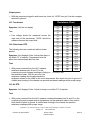
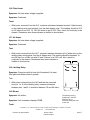
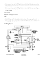
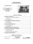
1
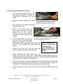
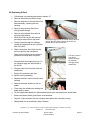
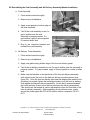
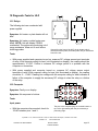
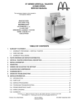
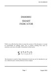
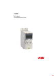
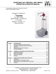
SERVICE MANUAL
HEATED LANDING ZONE (HLZ 18 AND HLZ 22)
This equipment chapter is to be inserted in the Equipment Manual.
MANUFACTURED BY FRYMASTER, L.L.C.
P.O. BOX 51000
SHREVEPORT, LOUISIANA 71135-1000
PHONE 1(318)865-1711
1 (800) 24 FRYER
TABLE OF CONTENTS
1. WARRANTY STATEMENT........................................................................................................... 1
1.1
WARRANTY PROVISIONS - HEATED LANDING ZONE ...................................................................................... 1
1.2
PARTS RETURN.................................................................................................................................................... 1
1.3
WARRANTY EXCLUSIONS................................................................................................................................... 1
2. PARTS ORDERING AND SERVICE INFORMATION ................................................................... 2
3. HEATED LANDING ZONE ........................................................................................................... 3
4. INSTALLATION/SETUP ............................................................................................................... 3
5. OPERATION................................................................................................................................. 3
6. HLZ MODEL/COMPONENT IDENTIFICATION ............................................................................ 4
7. HLZ COMPUTER OPERATION AND PROGRAMMING............................................................... 5
7.1
PROGRAMMING TEMPERATURE........................................................................................................................ 5
7.2
OPERATION .......................................................................................................................................................... 6
8. HLZ OPERATOR TROUBLESHOOTING ..................................................................................... 8
9. SERVICE INFORMATION .….…………..……………………………………………………..…..… 9
9.1 PARTS LIST…….……………………………………………………………………………………………………………....9
9.2 INTERIOR VIEW OF AN HLZ ….…………………….……………………………………………………………………….9
9.3 PROCEDURES..…………………………………………………………………………………………..…………..…....…11
10 DIAGNOSTIC TESTS…………………………………………..…………………………….…..…..….. ........................... 15
11 WIRING DIAGRAM………………………………………………………..……………….…………….............................. 18
Frymaster L.L.C., 8700 Line Avenue 71106, P.O. Box 51000, Shreveport, Louisiana 71135-1000
318-865-1711
FAX 318-862-2394
Printed in the United States
Service Hotline
1-800-24-FRYER
819-5659 (10/02)
THIS SERVICE MANUAL SUPERCEDES
ALL PREVIOUS EDITIONS OF THE HLZ SERVICE MANUAL.
FOR YOUR SAFETY
DO NOT STORE OR USE GASOLINE OR OTHER FLAMMABLE VAPORS AND LIQUIDS IN
THE VICINITY OF THIS OR ANY OTHER APPLIANCE.
DO NOT OPERATE OR SERVICE THE HLZ SERIES WITHOUT FIRST READING THIS
MANUAL.
DO NOT OPERATE THE HLZ SERIES UNLESS IT HAS BEEN PROPERLY INSTALLED
AND CHECKED.
DO NOT OPERATE THE HLZ SERIES UNLESS ALL SERVICE AND ACCESS PANELS
ARE IN PLACE AND PROPERLY SECURED.
DO NOT ATTEMPT TO REPAIR OR REPLACE ANY COMPONENT OF THE HLZ SERIES
UNLESS ALL POWER TO THE UNIT HAS BEEN DISCONNECTED.
USE CAUTION WHEN SETTING UP, OPERATING, OR CLEANING THE HEATED
LANDING ZONE TO AVOID CONTACT WITH HEATED SURFACES.
HAZARD COMMUNICATION STANDARD, (HCS) - THE PROCEDURES IN THIS MANUAL
INCLUDE THE USE OF CHEMICAL PRODUCTS. THESE CHEMICAL PRODUCTS WILL
BE PRINTED IN BOLD FACE, FOLLOWED BY THE ABBREVIATION (HCS) IN THE TEXT
PORTION OF THE PROCEDURE. SEE THE HAZARD COMMUNICATION STANDARD,
(HCS) MANUAL FOR THE APPROPRIATE MATERIAL SAFETY DATA SHEET(S), (MSDS).
Frymaster L.L.C., 8700 Line Avenue 71106, P.O. Box 51000, Shreveport, Louisiana 71135-1000
318-865-1711
FAX 318-862-2394
Printed in the United States
Service Hotline
1-800-24-FRYER
1. WARRANTY STATEMENT
The Frymaster Corporation makes the following limited warranties to the original purchaser only for this
equipment and replacement parts:
WARRANTY PROVISIONS - HEATED LANDING ZONE
A. The Frymaster Corporation warrants all components against defects in material and workmanship for a period
of 1 year.
B. All parts, with the exception of fuses, are warranted for 1 year after installation date of cabinet.
C. If any parts, except fuses, become defective during the first year after installation date, Frymaster will also pay
straight-time labor costs to replace the part, plus up to 100 miles/160 km of travel (50 miles/80 km each way).
PARTS RETURN
A. All defective in-warranty parts must be returned to a Frymaster Authorized Factory Service Center within 60
days for credit. After 60 days, no credit will be allowed.
WARRANTY EXCLUSIONS
This warranty does not cover equipment which has been damaged due to misuse, abuse, alteration, or accident
such as:
• improper or unauthorized repair;
• failure to follow proper installation instructions and/or scheduled maintenance procedures as prescribed in
your MRC cards;
• improper maintenance;
• damage in shipment;
• abnormal use;
• removal, alteration, or obliteration of the rating plate;
This warranty also does not cover:
• transportation or travel over 100 miles/160 km (50 miles/80 km each way), or travel time over two (2)
hours;
• overtime or holiday charges;
• consequential damages (the cost of repairing or replacing other property which is damaged), loss of time,
profits, use or any other incidental damages of any kind.
There are no implied warranties or merchantability or fitness for any particular use or purpose.
For international warranty, the above procedures apply, except that the customer is responsible for freight and
duty charges.
2. PARTS ORDERING AND SERVICE INFORMATION
Parts orders may be placed directly with your local Frymaster Factory Authorized Service Center
(FASC)/Distributor. A list of Frymaster FASC/ Distributors was included with the unit when shipped from the
factory. If you do not have access to this list, please contact the Frymaster Service Department at 1-800-24FRYER or 1-318-865-1711.
To speed up your order, the following information is required:
Model Number ______________________
Serial Number ______________________
Voltage ___________________________
Item Part Number ___________________
Frymaster L.L.C., 8700 Line Avenue 71106, P.O. Box 51000, Shreveport, Louisiana 71135-1000
318-865-1711
FAX 318-862-2394
Printed in the United States
Service Hotline
1-800-24-FRYER
Page 1
Quantity Needed ____________________
Service may be obtained by contacting your local Frymaster Authorized Service Center/Distributor. Service
information may be obtained by calling the Frymaster Service Department. The following information will be
needed in order to assist you quickly and efficiently:
Model Number _________________________
Serial Number _________________________
Nature of the Problem ___________________
_____________________________________
_____________________________________
_____________________________________
Also any other information which may be helpful in solving your service problem.
RETAIN AND STORE THIS MANUAL IN THE EQUIPMENT MANUAL FOR FUTURE USE.
Frymaster L.L.C., 8700 Line Avenue 71106, P.O. Box 51000, Shreveport, Louisiana 71135-1000
318-865-1711
FAX 318-862-2394
Printed in the United States
Service Hotline
1-800-24-FRYER
Page 2
3. HEATED LANDING ZONE
The Heated Landing Zone or HLZ is designed to hold assembled sandwiches. By circulating heated
air evenly across the open staging area, the Heated Landing Zone keeps sandwiches hot without
drying or cooking. The Heated Landing Zone meets all McDonald’s standards for safety, efficiency,
food safety, and cleanliness.
4. INSTALLATION/SETUP
Optional Burger Bumper
Installed (unit built before 10/98)
Upon arrival, inspect the HLZ for concealed damage.
Immediately report any damage to the delivering freight
company. Claims must be filed within 15 days after
receipt of the unit.
Make sure that the unit is placed on an even surface and
that the area surrounding the HLZ is free of clutter that
would interfere with air flow.
Computer
Cowl
Figure 1
INSTALL OPTIONAL BURGER BUMPER (Units built before 10/98)
The burger bumper may be placed on either side of the
HLZ to prevent pass through of product. Burger bumpers
are provided by the KES. See figure 1.
INSTALL FILTER SCREEN (Units built after 10/98)
The filter screen is design to prevent debris from entering
the Computer Cowl Assembly and clogging the blower
assembly. Simply fit the part on to the vent opening of the
computer cowl assembly. The filter screen will snap into
position. If equipped with an optional holding screw,
tighten screw to pull the filter screen snug into position.
POWER REQUIREMENTS:
•
Voltage – Two models are available: 208 VAC and 240 VAC*
•
Frequency - 60 Hz
•
Single Phase
•
20 amp Service
5. OPERATION
1. Plug the unit into the power source.*
2. See
“HLZ
COMPUTER
OPERATION
AND
PROGRAMMING, Section 7” for proper setup and
operation of the computer.
3. Place product in the HLZ in accordance with the
The filter screen snaps into place on rear of the
air-intake tower.
* If the 240 VAC model is operated on
208 VAC, the unit will heat slowly and
may not reach maximum temperature. If
the 208 VAC model is operated on 240
VAC, component damage is probable.
To ensure proper operation, the power
source should match the voltage on the
rating plate on the bottom of the HLZ.
THIS APPLIANCE IS EQUIPPED WITH A
GROUNDING PLUG FOR YOUR
PROTECTION AGAINST SHOCK
HAZARD AND MUST BE PLUGGED INTO
A PROPERLY GROUNDED
RECEPTACLE. DO NOT CUT OR
REMOVE THE GROUNDING PRONG
FROM THIS PLUG.
restaurant’s established procedures.
4. CLOSING - When closing the store, remove all product from the HLZ and perform daily preventive
maintenance in accordance with the MRC. Turn the computer OFF.
Frymaster L.L.C., 8700 Line Avenue 71106, P.O. Box 51000, Shreveport, Louisiana 71135-1000
318-865-1711
FAX 318-862-2394
Printed in the United States
Service Hotline
1-800-24-FRYER
Page 3
6. HLZ MODEL/COMPONENT IDENTIFICATION
Heated air flows
from the air
heater/blower
and heat rises
from the heater
plate.
Heater
Plate/Landing
Zone
Heater Plate
Calibration
Socket
Air Heater
Calibration
Socket
Power Cord
HLZ Computer
A look at the flow of
heated air around the HLZ
Blower Assembly
Heater plate
Heater Plate
Air Heater
Frymaster L.L.C., 8700 Line Avenue 71106, P.O. Box 51000, Shreveport, Louisiana 71135-1000
318-865-1711
FAX 318-862-2394
Printed in the United States
Service Hotline
1-800-24-FRYER
Page 4
7. HLZ COMPUTER OPERATION AND PROGRAMMING
Display
Air Heater
Temperature
Heater Plate
Temperature
Switch (1)
Switch (4)
ON/OFF Switch
Check or
Program Switch
Down Switch (2)
Up Switch (3)
7. 1 Programming Temperature
You are able to program the setpoint temperature of both the air heater and the heater plate
via the computer interface. The heater plate factory default is set to the McDonald’s standard
of 160°F. The air heater factory default is set to the McDonald’s standard of 220°F. If the
factory default temperature settings are acceptable, skip to Section 7.2, Page 6.
Ensure that the HLZ computer is in the OFF position (nothing in the display).
Press the check switch and enter the code (1,2,3,3). The numerals in the upper right-hand
corner represent the key number.
Press
, then
,
,
,
in order
The display will read SET and the LEDs on both the Heater Plate Switch (1) and the Air Heater
Switch (4) will light. Press the switch that corresponds to the heater you wish to program.
Frymaster L.L.C., 8700 Line Avenue 71106, P.O. Box 51000, Shreveport, Louisiana 71135-1000
318-865-1711
FAX 318-862-2394
Printed in the United States
Service Hotline
1-800-24-FRYER
Page 5
Display reads SET,
Press
and
LED’s light.
to program the heater plate or
to
program the air heater.
Press the Up and Down Arrow Keys to achieve the desired set-point temperature, then press
the Check Switch once. Both heater LEDs will again light.
Press
or
to get desired setpoint, then press
to lock the temperature in.
If you are finished with programming both heaters, press the Check Switch again to store the
programmed setpoints and exit the programming mode OR to change the setpoint temperature
for the other heater, press the corresponding Heater Switch (1 or 4). Program as described in
Step 4.
When finished, press
again to exit programming
mode. To change the other heater, press
program the heater plate or
to
to program the air
heater, then go to Step 4 for instructions.
7.2 Operation
1.
Press the ON/OFF switch to the ON position (the display will light and cycle through an
initialization sequence). The display will read –LO- until the air heater and heater plate are
within 15°F of setpoint. It will take approximately 10 minutes for the HLZ to achieve
operating temperature.
Frymaster L.L.C., 8700 Line Avenue 71106, P.O. Box 51000, Shreveport, Louisiana 71135-1000
318-865-1711
FAX 318-862-2394
Printed in the United States
Service Hotline
1-800-24-FRYER
Page 6
Press
to turn on the computer.
The display will read
— LO — until both heaters are
within 15°F of setpoint
NOTE: A small LED will light in the display when either the heater plate or air heater is
energized.
Air Heater
R E
d¡
y
Heater Plate
When the HLZ is ready for operation, the display reads REdY (ready). Place product in the
HLZ in accordance with the restaurant’s established procedures.
NOTE: To check the actual temperature of a heater, press the corresponding Temperature
Switch once. To check the setpoint temperature of a heater, press the switch twice (an
indicator will light when the setpoint is displayed).
2 2 0
Setpoint
Temperature
Frymaster L.L.C., 8700 Line Avenue 71106, P.O. Box 51000, Shreveport, Louisiana 71135-1000
318-865-1711
FAX 318-862-2394
Printed in the United States
Service Hotline
1-800-24-FRYER
Page 7
8. Operator Troubleshooting Guide
Symptom
Possible Cause
No computer display; no flow from
air tower
No power
Circuit breaker out
Low voltage
Bad fuse
Bad transformer
Hi-limit out
No flow from air tower
Bad latching relay
After 20 minutes of operation
computer display shows PROB
RTD probe has failed. Isolate failed
component by checking temperature of
air and heater plate with the temperature
display keys on the computer. The plate
temperature should be within ± 15°F of
setpoint. The air heat should be within ±
25°F of setpoint. If both temperatures are
good, the computer is likely bad.
After 20 minutes of operation
computer display shows HI
Plate heater, plate heater relay or RTD
are faulty.
After 20 minutes of operation
computer display shows LO
Air heater, air heater relay or RTD are
faulty
Frymaster L.L.C., 8700 Line Avenue 71106, P.O. Box 51000, Shreveport, Louisiana 71135-1000
318-865-1711
FAX 318-862-2394
Printed in the United States
Service Hotline
1-800-24-FRYER
Page 8
9. SERVICE INFORMATION
9.1 PARTS LIST
Description
Transformer,
208V/240V/12V
Transformer 230V (CE)
Air Heater, 208V
Air Heater 230V (CE)
Air Heater, 240V
Shield, HLZ Heater
Air RTD Probe
Bracket, RTD/Thermocouple
Delivery Air Back W/A
Air Thermocouple
HLZ 22 Plate, Heater with
RTD and Thermocouple,
208V/240V (22”x15.5”)
HLZ 18 Plate, Heater with
RTD and Thermocouple,
208/240V (22”x12”)
Line Filter (CE)
Plug Assembly, Computer
Air Relay, SS Service
Part Number
807-0979
807-3185
807-2945
807-3630
807-3011
900-8486
807-3036
900-8366SP
823-2741
807-3043
806-9238
806-9239
807-2818
806-9636
826-2038
Plate Relay, SS Service
Relay, Latching
Blower, 230V (CE)
Blower, 208V/240V
Hi-Limit
Fuse Block
Fuse, 20A
Cordset, Twist Lock, HLZ
Cordset, CE
Cordset, Japanese
RTV#108 Silicone Rubber
Gasket, HLZ Plate/Cowl
Filter Screen
Acrylic Tape
Computer Assembly, HLZ
Cowl Assembly
Cowl Tinnerman Clips
Front Delivery Air W/A
Lug, Grounding 14 GA
Pad, HLZ Leg
826-1958
807-3021
807-3691
807-3637
807-3631
807-2820
807-2819
807-3020
807-1696
807-3419
811-0511
816-0418
810-1724
811-1042
106-0534
823-2745
809-0448
823-2742
807-2972
826-1561
9.2 Interior view of an HLZ (Cowl Assembly removed)
Hi-limit (left above) and air thermocouple
(bottom right above) and air RTD.
Solid state
relays
Transformer and fuses.
HLZ with heater plate elevated.
Frymaster L.L.C., 8700 Line Avenue 71106, P.O. Box 51000, Shreveport, Louisiana 71135-1000
318-865-1711
FAX 318-862-2394
Printed in the United States
Service Hotline
1-800-24-FRYER
Page 9
9.3 Repair Procedures
1. Accessing the interior of the HLZ (Set up for
testing):
a. Disconnect power cord from outlet.
b. Turn unit on its side. Remove the five access screws
located on the bottom of the unit.
c. Then set the unit back down on its base. Place paper
towels on the heater plate to protect it from
scratching. Remove the cowl assembly and lay the
cowl on the heater plate while troubleshooting.
4
3
2
12A
1
4
3
1
2
12A
240VAC
Heater Plate
240VAC
Heater plate
relay
Air heater
relay
9.4
The cowl assembly is held on by five
screws, which are removed from the
bottom of the unit.
The relays are best replaced by removing the plate
that holds them in place. Two 5/16 nuts hold the
plate in place.
Front of HLZ
Replacing Solid State Relays:
a. Avoid miswiring. Examine the terminals carefully and take notes to avoid
miswiring.
b. Remove the plate holding the relay assembly. The nuts holding the relays in place
are easier to reach with the assembly out of the unit.
c. Remove the two nuts holding relays to plate.
d. Apply heat sink compound and install new relay.
e. Reverse this procedure to reinstall.
Frymaster L.L.C., 8700 Line Avenue 71106, P.O. Box 51000, Shreveport, Louisiana 71135-1000
318-865-1711
FAX 318-862-2394
Printed in the United States
Service Hotline
1-800-24-FRYER
Page 10
9.5 Opening the Air Delivery
Tower:
a. The air thermocouple and
air RTD are located in the
air delivery tower.
To
access them, the front air
delivery assembly must be
removed.
b. Insert a 5/16” nut driver
Components in the rear tower are
accessed by loosening two nuts, one
through the front air
under each end of the overhang.
delivery assembly access
holes and turn the nuts
counterclockwise to loosen. Do not
remove the nuts. Grab the bottom
flange of the front air delivery, push upwards and pull towards you. Be careful,
there are two tabs on the front air delivery bottom that must clear the heater
plate to allow removal of the front air delivery.
9.6 Replacing Air Thermocouple and
Air RTD Probe:
a. Follow procedures in section 9.3.
to access the Air Delivery tower
components.
b. Cut old lead wires close to the
faulty air thermocouple or Air RTD
Probe. Disconnect lead wires at
the test plug. Leave lead wires in
place for now.
Air Thermocouple
Air RTD Probe
c. Remove the faulty Air Thermocouple or Air RTD Probe from the bracket.
d. Install the replacement Air Thermocouple or Air RTD Probe into the bracket.
e. Attach the new lead wires to the old lead wires on the Air Thermocouple or Air
RTD Probe on the bracket-side of unit. Grasp the old leads at the test plug and
gently pull the leads towards you.
f. Once the new lead wires have been pulled through, disconnect the old lead
wires, and attach the new leads to the test plug.
g. Go to step 9.3.2 and reassemble the air delivery tower.
Frymaster L.L.C., 8700 Line Avenue 71106, P.O. Box 51000, Shreveport, Louisiana 71135-1000
318-865-1711
FAX 318-862-2394
Printed in the United States
Service Hotline
1-800-24-FRYER
Page 11
9.7 Accessing the Plate and Air Heaters:
a. Use the following method to remove the
plate heater assembly or access the
compartment underneath the plate
heater.
b. Remove the cowl assembly per steps
9.3.
c. Then remove the air delivery assembly
following steps in 9.5.
d. Insert a thin, sharp knife, i.e.
Exacto-type, between the heater
plate and the HLZ chassis.
Carefully cut the silicon adhesive
between the heater plate and the
chassis.
After cutting the acrylic adhesive between the
heater plate and the HLZ chassis, use a
screwdriver to gently lift the heater plate.
Gently lift the heater plate, which may still be stuck to
e. Lift the heater plate by prying up the adhesive. Apply new acrylic tape to the chassis
one end of the heater plate away before reinstalling the heater plate.
from the HLZ chassis. The plate is
held in place by an acrylic tape. It will be difficult to NOTE: A hot platen is
break the bond between the heater plate and easier to remove. The
chassis.
heat makes the
adhesive holding the
f. Remove acrylic tape from the heater plate and platen in place more
frame to prevent rebounding while servicing.
pliable.
g. When reinstalling the heater plate, apply new
acrylic tape to the HLZ chassis first. Then position the heater plate standing on
its side against the back air delivery assembly. The heater plate leads should be
coming off the “top” edge of the heater plate.
h. Once the heater plate is aligned properly with the HLZ chassis, gently lower the
heater plate until the plate end with the lead wires is approximately 2 inches from
the chassis. Feed the leads through the opening in the chassis wall.
i.
Finish lowering the heater plate into place and connect the heater plate lead
wires.
Frymaster L.L.C., 8700 Line Avenue 71106, P.O. Box 51000, Shreveport, Louisiana 71135-1000
318-865-1711
FAX 318-862-2394
Printed in the United States
Service Hotline
1-800-24-FRYER
Page 12
9.8 Replacing Hi-limit
a. Follow steps in Accessing plate and air heaters, 9.7.
b. Remove the shield over the air heater
c. Remove the brace on the left side of the
base assembly, exposing the wire
raceway.
d. Remove the grommets the hi-limit
wiring passes through.
e. Remove the existing hi-limit and pull
wiring through cabinet.
f.
Mount the hi-limit on the the spacers,
providing a stand-off from the panel..
g. Push the wires through the raceway
toward the transformer on the controller
side of the HLZ.
The wires for the hi-limit are routed through the hole
used by the RTD wiring. Slip the wires into slot
(shown above) and into the hole.
h. Slip the wires from the hi-limit into the
area occupied by the transformer.
i.
Slip the hi-limit wires into the removed
grommets and snap back into place.
j.
Plug the black wire leading from pin 1 in
the computer plug into the terminal of
the hi-limit.
The wire is routed
from the air
cowling, through
the raceway,
emerging at the
transformer.
k. Plug the other hi-limit terminal onto the
transformer.
l.
Ensure all connections are tight.
m. Retie the wiring assembly
n. Replace the brace, which forms the wire
raceway.
o. Replace the metal shield over the air
heater.
p. Clear away the old adhesive holding the
heater plate in place.
q. Put the single-back adhesive in place adhesive-side down and position the heater plate.
r.
Ensure the heater plate’s ground wire is reconnected.
s. Plug the 15-pin connector into the computer and replace the controller housing.
t.
Reassemble unit as described in step 9.9 below.
Frymaster L.L.C., 8700 Line Avenue 71106, P.O. Box 51000, Shreveport, Louisiana 71135-1000
318-865-1711
FAX 318-862-2394
Printed in the United States
Service Hotline
1-800-24-FRYER
Page 13
9.9 Reinstalling the Cowl Assembly and Air Delivery Assembly/Gasket Installation
a. Cowl Assembly:
1. Clean surface area thoroughly.
2. Remove any old adhesive.
3. Apply a new gasket to bottom edge of
the cowl assembly.
Apply gasket or sealant along this edge
4. Test fit the cowl assembly to see if a
gap is visible once the cowl
assembly is properly seated. If a
gap remains, apply a second gasket
to create a better seal.
5. Plug in the computer harness and
reinstall the cowl assembly .
b. Air Delivery Tower Assembly:
1. Clean surface area thoroughly.
Apply gasket or sealant along this edge
2. Remove any old adhesive.
3. Apply new gasket along bottom edge of the front air delivery panel.
4. Test fit the air delivery assembly to see if a gap is visible once the assembly is
properly seated. If a gap remains, apply a second gasket to create a better
seal.
5. Make sure the brackets on the back-side of the front air delivery assembly
slide up and under the nuts on the back air delivery mounting screws (see
figure 9-8). Once the front air delivery tabs clear the heater plate and the front
air delivery is seated, tighten the mounting screws to pull the front air delivery
flush against the back air delivery assembly. An air seal is created between
the lower sections of the front air delivery and back air delivery assemblies.
This seal forces the heated air up the rear and then down the front-side of the
front air delivery assembly. After reinstalling the air delivery tower, reseal
around the heater plate with RTV #108 silicone rubber compound, PN 8110511.
Frymaster L.L.C., 8700 Line Avenue 71106, P.O. Box 51000, Shreveport, Louisiana 71135-1000
318-865-1711
FAX 318-862-2394
Printed in the United States
Service Hotline
1-800-24-FRYER
Page 14
10 Diagnostic Tests for HLZ
10.1 Relays
4
4
Symptom: Air heater or plate heater will not
heat.
Symptom: Air heater or plate heater over
heats. NOTE: Unit will display PROB if
overheated. The probes are producing out of
range resistance. Allow unit to cool before
checking probes.
Input
Input
Output
2
Output
The following tests are conducted with
power applied.
2
1
1
3
3
Viewed from the front of the HLZ, the air heater relay is
nearest the heater plate; the heater plate relay is nearest the
front of the unit.
Tests:
•
With power supplied and computer turned on, measure DC voltage across input terminals
of relay. With computer calling for heat ( dot illuminated on display), the reading should be
approximately 12 VDC. Failure to measure DC voltage points to a problem with the
computer or connection.
•
With power supplied and computer turned on, measure AC voltage across output
terminals of relay. With computer calling for heat (dot illuminated in display), the reading
should be .6 - .9 VAC. Reading line voltage with the computer calling for heat, indicates a
failure of the computer to supply the necessary DC voltage to close the relay or a failure
of the relay.
10.2 Computer
Symptom: Faulty or no display.
Symptom: No response to buttons.
Tests:
3
6
9
12 15
2
5
8
11 14
1
4
7
10 13
Input power
•
With the computer disconnected, check for
12VAC between pins 1 and 3.
The pins in the computer plug are counted bottom to
top, left to right starting with the pin marked by a
protruding ridge.
Frymaster L.L.C., 8700 Line Avenue 71106, P.O. Box 51000, Shreveport, Louisiana 71135-1000
318-865-1711
FAX 318-862-2394
Printed in the United States
Service Hotline
1-800-24-FRYER
Page 15
Output power
•
With the computer plugged in and turned on, check for 14VDC from pin 5 on the computer
terminal to ground.
Resistance Chart
10.3 Transformer
Symptom: Unit has no display
Test:
•
Line voltage should be measured across the
input side of the transformer; 12VAC should be
measured across the output side.
10.4 Plate Heater RTD
The following tests are conducted without power
applied.
Symptom: Unit displays Probe. Actual plate temp is
not within 5°F of setpoint. Temperature must be
taken from thermocouple built into unit.
Test:
•
Centegrade
21
27
32
38
43
49
54
60
66
71
77
82
88
93
99
104
110
116
121
127
132
138
143
149
Fahrenheit
70
80
90
100
110
120
130
140
150
160
170
180
190
200
210
220
230
240
250
260
270
280
290
300
Ohms
1080
1101
1122
1143
1164
1185
1206
1226
1247
1268
1289
1309
1330
1350
1371
1391
1412
1432
1453
1473
1493
1514
1534
1554
With power removed from the HLZ, measure
resistance between pins 9 and 13 on the
computer plug and compare readings to listing on Resistance chart
the resistance chart. With the unit cool, the
resistance reading should approximate the
resistance shown on the chart for the room temperature. Also check for short to ground. A
chaffed wire shorting to the chassis can produce resistance readings within proper range.
10.5 Air RTD
Symptom: Unit displays Probe. Actual air temp is not within 5°F of setpoint.
Test:
•
With power removed from the HLZ, measure resistance between pins 14 and 15 on the
computer plug and compare with air temperature on the resistance chart in this section.
Also check for short to ground. A chaffed wire shorting to the chassis can produce
resistance readings within proper range.
Frymaster L.L.C., 8700 Line Avenue 71106, P.O. Box 51000, Shreveport, Louisiana 71135-1000
318-865-1711
FAX 318-862-2394
Printed in the United States
Service Hotline
1-800-24-FRYER
Page 16
10.6 Plate Heater
Symptom: No heat when voltage is applied.
Symptom: Overheats
Tests:
•
With power removed from the HLZ , measure resistance between terminal 4 (white wires)
on the latching relay and terminal 4 on the plate heater relay. The reading should be 215
to 230 ohms on an HLZ 18; 150-180 ohms on an HLZ 22. Also, check for continuity to the
chassis. Resistance seen there indicates a chaffed or shorted wire.
10.7 Air Heater
Symptom: No heat when voltage is applied.
Symptom: Overheats
Test:
•
With power removed from the HLZ , measure resistance between pin 4 (white wire) on the
latching relay and terminal 4 on the air heater relay. The reading should be between 18
and 26 ohms on a 208V unit and 25 and 33 ohms on a 240V unit. Also, check for
continuity to the chassis. Resistance seen there indicates a
chaffed or shorted wire.
10.8 Latching Relay
Symptom: Computer calls for heat (dot illuminated). No heat
from plate and blower doesn’t operate.
Test:
•
With power removed from the HLZ and the wire removed
from pin 1 or 0 of the latching relay, measure resistance
between pins 1 and 0. It should be between 79 and 89 ohms.
10.9 Blower
Symptom: No airflow.
The latching relay is
positioned in the HLZ
with the 0 and 1
terminals facing the front
of the unit.
Symptom: Unit overheats; displays PROB.
Tests:
Frymaster L.L.C., 8700 Line Avenue 71106, P.O. Box 51000, Shreveport, Louisiana 71135-1000
318-865-1711
FAX 318-862-2394
Printed in the United States
Service Hotline
1-800-24-FRYER
Page 17
•
Remove power from unit. On 208V units, disconnect black and white wires connecting
blower to heat and latching relays. The resistance between the wires should be between
55 and 65 ohms.
•
Remove power from unit. On 240V units, disconnect red and white wires connecting
blower to heat and latching relays. The resistance between the wires should be between
62 and 72 ohms.
10.10 Hi-limit
Symptom: No display on controller.
Test:
•
The hi-limit is in the 12-volt output from the transformer. Remove power from unit.
Disconnect the white braided lead from the wire leading from pin 1 on the computer plug.
Disconnect the white braided lead from the 12-volt side of the transformer. Check
continuity in the hi-limit circuit.
11 Wiring Diagram
Frymaster L.L.C., 8700 Line Avenue 71106, P.O. Box 51000, Shreveport, Louisiana 71135-1000
318-865-1711
FAX 318-862-2394
Printed in the United States
Service Hotline
1-800-24-FRYER
Page 18