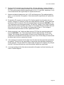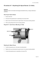
1
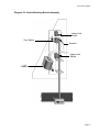
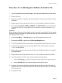
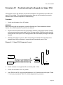
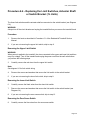
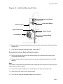
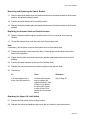
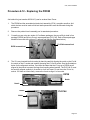
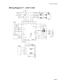
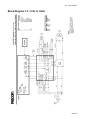
9.45, 9.45i Treadmill
9.45, 9.45i Treadmill
Warning: This service manual is for use by Precor trained service providers only.
If you are not a Precor Trained Servicer, you must not attempt to service any Precor Product;
Call your dealer for service.
This document contains information required to perform the majority of troubleshooting, and
replacement procedures required to repair and maintain this product.
This document contains general product information, software diagnostic procedures (when
available), preventative maintenance procedures, inspection and adjustment procedures,
troubleshooting procedures, replacement procedures and electrical block and wiring diagrams.
To move directly to a procedure, click the appropriate procedure in the bookmark section to the
left of this page. You may “drag” the separator bar between this page and the bookmark section
to change the size of the page being viewed.
© 2003 Precor Incorporated
Unauthorized Reproduction and Distribution Prohibited By Law
Page 1
9.45, 9.45i Treadmill
Section One - Things you Should Know
About This Appendix
Precor has re-designed the M9.45 treadmill several times. Units with the original design have
serial numbers starting with '1L' and were manufactured between January 24, 1995 and March
25, 1996. The M9.45 treadmill was then redesigned with serial numbers starting with '2P' and
were manufactured between March 26, 1996 and November 15, 1997. The 9.45i uses serial
numbers starting with ‘3Y’ and started in production on November 16, 1997. The 9.45i is the only
version of the 9.45 that is currently in production. This document will refer to the three versions
as follows 9.45 (1Y), 9.45 (2P) and 9.45i (3Y).
Section One, Things You Should Know. This section includes general information and
technical specifications. Read this section, as well as the M9.45 Treadmill Owner’s Manual,
before you perform the maintenance procedures in this manual.
Section Two, Software Features. Precor’s M9.45 Treadmill is programmed with several
diagnostic and setup features. This section contains the procedures you need to access the
diagnostic features on this treadmill.
Section Three, Checking Treadmill Operation. This section provides you with a quick way of
checking treadmill operation. Check treadmill operation at the end of a maintenance procedure
and when it is necessary to ensure that the treadmill is operating properly.
Section Four, Inspection and Adjustment Procedures. Perform inspection procedures when
a trouble symptom points to a particular problem and after removing and replacing major
components. Many maintenance problems can be fixed by adjusting various treadmill
components. This section also provides you with the step-by-step procedures required to make
these adjustments.
Section Five, Troubleshooting Procedures. The diagnostic and troubleshooting procedures
contained in this section should be performed when it is necessary to isolate a problem to a
particular component.
Section Six, Replacement Procedures. When a treadmill component must be replaced, go to
this section and follow the step-by-step procedures required to remove and replace the
component.
Section Seven, Wiring and Block Diagrams. This section includes wiring and block diagrams
for all versions of the 9.45.
General Information
For the latest exploded view, part number and part pricing information, visit the Precor dealer
website at “www.precor.com/Dealer”.
Page 2
9.45, 9.45i Treadmill
Technical Specifications
Physical Specifications
Length:
Width:
Height:
Running surface:
Motor:
Speed:
Incline:
Power:
Weight:
Shipping weight:
71 inches or 180 cm (Extended deck treadmills
are 5 inches longer)
Handrails 31.5 inches (80 cm)
Base 28.5 inches (72 cm)
50 inches (127 cm)
53 inches by 18 inches (135 cm by 46 cm)
2 hp continuous duty
0.5 to 10 mph (0.8 to 16 kph)
10 mph is equivalent to a 6 minute mile
-2% to +12% grade
50/60 Hz 120v AC (dedicated circuit)
50/60 Hz 240v AC (dedicated circuit)
265 lbs (119 kg)
326 lbs (147 kg)
About The Smart Rate System
The Smart Rate system is the heart rate system mounted in the display housing. The Smart Rate
system receives a heart rate signal from chest strap transmitter worn by the user. Smart Rate
software displays a heart range on green, red and yellow LED's mounted on the upper PCA. The
LED’s indicate whether the heart rate is below, within or above the desired rang.
Page 3
9.45, 9.45i Treadmill
Procedure 2.1 - Accessing the M9.45 (1L or 2P) Treadmill's
Diagnostic Program
Procedure
1.
Plug the power cord into the wall outlet, then turn on the treadmill with the circuit breaker.
2.
The diagnostic program provide six different routines to aid it testing and trouble diagnosis.
3.
On 9.45 (1Y & 2P units), with the PRECOR M9.45 banner scrolling, press and hold ENTER
until the software version number is displayed in the right display windows. On units that
have serial numbers starting with '2P', the part number of the PROM will also be displayed.
4.
The first routine is the LED display test. The routine will light every LED on the display as the
test proceeds. It is necessary to watch the display to see if an LED does not light.
5.
On 9.45 (1L units) the second routine is the lift test. The lift test takes the lift through each of
the critical lift positions. In doing so it tests the performance of the zero switch, upper limit
switch, lower limit switch and rotation sensor. Press ENTER to continue.
6.
On 9.45 (2P) units the second routine is lift calibration. The lift calibration number indicates
the physical position of the lift. As lift is operated the lift calibration number will track the lift’s
physical position. The lift calibration number will be used to initialize the lift. Press the
INCLINE keys while you watch the right display window (see Diagram 2.1). The lift
calibration number increments as the INCLINE ▲ key is pressed and decrements as the
INCLINE ▼ key is pressed. Press ENTER to continue.
7.
The third routine is the power bits display. Power bits is a number that indicates the amount
of time that power is applied to the drive motor (duty cycle). The power bit number reflects
changes in speed and load. Power bits and running belt speed will; be displayed. Notice that
the power bits number will increase or decrease as speed and/or load is increased or
decreased. The power bit number can be used to determine treadmill loading. Press
ENTER to continue.
8.
The fourth routine is the keypad test. Seven dashed lines will appear on the display. Each
dash will correspond to a key on the display. Press each key one at a time, the
corresponding dash will enlargen, indicating the key that was pressed. Use this test to
determine if the keys are functioning properly. Press the INCLINE ▼ and SPEED ▲ keys,
simultaneously to continue.
9.
The fourth routine is the safety key test. When the safety key is inserted SAFE ON is
displayed in the right display window. Remove the safety key from the upper display module
while you watch the right display window, SAFE OFF is displayed. Replace the safety key
and press ENTER to continue.
10. The fifth routine is the heart rate test. When a chest strap transmitter or test transmitter is
used, the heart rate will be displayed. Press ENTER to continue.
Page 4
9.45, 9.45i Treadmill
11. The last routine is the circuit breaker trip test. This test checks the ability of the treadmill to
trip the circuit breaker under software control. If the STOP key is pressed and held the trip
signal will be sent to the circuit breaker and the circuit will trip, shutting off the treadmill. If
you do not wish to trip the circuit breaker, press the ENTER key to exit the diagnostic
program.
Diagram 2.1 - Display Housing, 9.45 (1Y & 2P)
Page 5
9.45, 9.45i Treadmill
Procedure 2.2 - Accessing the M9.45i (3Y) Treadmill's
Diagnostic Program
Procedure
1.
Plug the power cord into the wall outlet, then turn on the treadmill with the circuit breaker.
2.
The diagnostic program provide six different routines to aid it testing and trouble diagnosis.
3.
For the purpose of accessing the various software routines, including the diagnostics
program, the display housing keys are hypothetically numbered 1 to 7 from left to right.
4.
With the PRECOR M9.45 banner scrolling, press keys RESET,5,1,7,6,5,7,6,1, sequentially
(See Diagram 2.2).
5.
The first routine is the LED display test. The routine will light every LED on the display as the
test proceeds. It is necessary to watch the display to see if an LED does not light..
6.
The second routine is lift calibration. The lift calibration number indicates the physical
position of the lift. As lift is operated the lift calibration number will track the lift’s physical
position. The lift calibration number will be used to initialize the lift. Press the INCLINE keys
while you watch the right display window (see Diagram 2.2). The lift calibration number
increments as the INCLINE ▲ key is pressed and decrements as the INCLINE ▼ key is
pressed. Press ENTER to continue.
7.
The third routine is the power bits display. Power bits is a number that indicates the amount
of time that power is applied to the drive motor (duty cycle). The power bit number reflects
changes in speed and load. Power bits and running belt speed will; be displayed. Notice that
the power bits number will increase or decrease as speed and/or load is increased or
decreased. The power bit number can be used to determine treadmill loading. Press
ENTER to continue.
8.
The fourth routine is the key pad test. Seven dashed lines will appear on the display. Each
dash will correspond to a key on the display. Press each key one at a time, the
corresponding dash will enlargen, indicating the key that was pressed. Use this test to
determine if the keys are functioning properly. Press the INCLINE ▼ and SPEED ▼ keys,
simultaneously to continue
9.
The fifth routine is the safety key test. When the safety key is inserted SAFE ON is
displayed in the right display window. Remove the safety key from the upper display module
while you watch the right display window, SAFE OFF is displayed. Replace the safety key
and press ENTER to continue.
10. The sixth routine is the heart rate test. When a chest strap transmitter or test transmitter is
used, the heart rate will be displayed. Press ENTER to continue.
Page 6
9.45, 9.45i Treadmill
11. The last routine is the circuit breaker trip test. This test checks the ability of the treadmill to
trip the circuit breaker under software control. If the STOP key is pressed the trip signal will
be sent to the circuit breaker and the circuit will trip, shutting off the treadmill. If you do not
wish to trip the circuit breaker, press the ENTER key to exit the diagnostic program.
Diagram 2.2 - Display Housing, 9.45i (3Y)
Page 7
9.45, 9.45i Treadmill
Procedure 2.3 - Resetting All User Information
This procedure completely resets the M9.45 user statistics. All previously-saved user information
will be either reset to zero or changed to default values. All odometers will be reset to zero. If you
want to save accumulated user information and odometer readings, record the information
before performing this procedure.
Note: This procedure is not available on the 9.45i. User stats must be reset individually per
Procedure 2.4.
Procedure
1.
Plug the power cord into the wall outlet, then turn on the treadmill with the circuit breaker.
2.
With the PRECOR M9.45 or PRECOR M9.45i banner scrolling, press the INCLINE ▲,
INCLINE ▼, SPEED ▲, and SPEED ▼ keys simultaneously and hold them for approximately
five seconds (or until zeros are displayed in the right display windows). Release the keys.
3.
Watch the electronic display. The right middle display window:
a
Resets to all zeros, then increments to 119
b
Resets to 1000, then increments to 1119
c
Resets to 2000, then increments to 2119
d
Resets to 3000, then increments to 3119
e
Displays the User ID prompt.
Note:
If the upper PCA or prom is replaced, all user information will be re-initialized.
Page 8
9.45, 9.45i Treadmill
Procedure 2.4 - Resetting an Individual User’s Information
This procedure resets accumulated user information and odometer readings for an individual
User ID. All previously-saved user information for a selected User ID will be either reset to zero or
changed to default values. The odometer reading for the selected User ID will be reset to zero.
Procedure
1.
Plug the power cord into the wall outlet, then turn on the treadmill with the circuit breaker.
2.
With the PRECOR M9.45 or PRECOR M9.45i banner scrolling, press any key.
3.
At the User ID prompt, select the User IDs to be reset using the SPEED ▲ (or INCLINE ▲)
and SPEED ▼ (or INCLINE ▼) keys.
4.
Press the STOP and QUICKSTART keys together and hold them for approximately two
seconds (or until the right middle display window displays one of the numbers sets in
Procedure 2.2, step 3a, 3b, 3c or 3d).
5.
If you do not observe the values listed in Procedure 2.2, step 3a, 3b, 3c or 3d...
THEN...
OTHERWISE...
Replace the upper PCA as described in
This procedure is complete.
Procedure 5.2 of the Residential Treadmill
Service Manual.
Note:
If the upper PCA is replaced, all user information will be re-initialized.
Page 9
9.45, 9.45i Treadmill
Procedure 2.5 - Displaying the Treadmill Odometer and Error
Code Log
Procedure
1.
Plug the power cord into the wall outlet, then turn on the treadmill with the circuit breaker.
2.
On 9.45 (1L or 2P units), with the PRECOR M9.45 banner scrolling, press the ENTER,
SPEED ▼ and SPEED ▲ keys, simultaneously. Continue to hold the keys until the message
TREADMILL ODOMETER scrolls across the left display window. On 9.45 (3Y units), press
keys RESET,6,5, sequentially.
Note:
The right display window displays total miles or kilometers on the treadmill (see Diagram 2.3).
The top display window shows the most significant bits of the number; the lower display window
shows the least significant bits of the number. The number displayed is 102,187,723 (in miles or
kilometers).
Diagram 2.3 - Odometer Reading For the Treadmill
0 0 0 1
0 2 1 8
7 7 2 3
3.
Press ENTER to access the error code log.
Page 10
9.45, 9.45i Treadmill
4.
There are five error code log positions. The error code log is displayed and scrolls across
the left display window (see Diagram 2.4). Use the SPEED ▼ (or INCLINE ▼) and SPEED ▲
(or INCLINE ▲) keys to scroll through the error code log. The most recent error condition will
be displayed in position 1 and the oldest error will be displayed in position 5. When an error
is added to a full log the new error will be inserted in position 1 and all other logs will be
pushed down one position. The error that was in position 5 will be lost.
5.
Once you have completed the diagnosis and repair of the treadmill, it is generally desirable
to clear the error code log. Then any subsequent error that are logged will be known to be
new error conditions. To clear the error code log, press the QUICK START and STOP keys
simultaneously. Or, press ENTER to retain the current error information and return to the
User ID prompt.
Diagram 2.4 - Error Code Log
6.
No
Err:
22
Err
1
2
The example above (Diagram 2.4) shows an “Error 22” in position 1 and “No Error” in
position 2.
Page 11
9.45, 9.45i Treadmill
Procedure 2.6 - Selecting United States Standard or Metric
Units
Selecting United States standard units causes data to be displayed in feet, miles and pounds.
Metric data is displayed in meters, kilometers and kilograms.
Procedure
1.
Plug the power cord into the wall outlet, then turn on the treadmill with the circuit breaker.
2.
Choose one:
IF...
You wish to verify the measurement
standard the treadmill is currently using
before you change the standard
THEN...
Continue with the next step
You wish to change the measurement
standard the treadmill is using
Skip to Step 5
Checking the Measurement Standard
3.
Press ENTER until the WEIGHT indicator light appears.
4.
Watch the number displayed in the left display window while you press the SPEED ▲ key
five or six times.
Note:
If the treadmill is using United States standard units, the numbers in the left display window are
displayed multiples of 5 (such as 160, 165, 170, 175, etc.). If the units are displayed in multiples
of 2 or 3, the treadmill set for metric units.
Changing the Measurement Standard
5.
Press and hold STOP to return the PRECOR M9.45 banner.
6.
On 9.45 (1L or 2P units), press the QUICK START and then the SPEED ▲ key. Hold both
keys for 3–5 seconds, then release. On 9.45 (3Y units), press keys RESET,5,6,7,1,
sequentially.
Note:
On 9.45 (1L or 2P units), releasing the QUICK START key before the SPEED ▲ key when you
perform the next step may cause the selected measurement standard to change to the alternate
Page 12
9.45, 9.45i Treadmill
measurement standardUse the SPEED ▲ or SPEED ▼ keys to select the alternate measurement
standard.
7. Press ENTER twice to return to the User ID prompt.
Page 13
9.45, 9.45i Treadmill
Procedure 2.7 - Determining Software Version Numbers
Software version numbers are invaluable for tracking and identifying problems and staying aware
of changes to the operation and features of the product.
Procedure
1.
Plug the power cord into the wall outlet, then turn on the treadmill with the circuit breaker.
2.
On 9.45 (1L or 2P units), with the PRECOR M9.45 banner scrolling, press the ENTER key.
On 9.45 (3Y units), with the PRECOR M9.45 banner scrolling, press keys
RESET,5,1,7,6,5,7,6,1, sequentially.
3.
Note the version number displayed in the right middle display window.
Note:
If you cannot determine the software version number in this manner, look at the label on the
PROM mounted on the upper PCA. The part number stamped on the PROM indicates the
software version number.
Page 14
9.45, 9.45i Treadmill
Procedure 2.8 - Documenting Software Problems
When a problem is found with either the software or upper or lower PCA’s, record the information
listed below. If you isolated the problem to either the PROM, upper PCA, or lower PCA, include
the information you recorded with the malfunctioning PROM or PCA when you ship it to Precor.
When a problem occurs, record the following information:
•
•
Model and serial number
Software version number
Note:
Determine the version number as in Procedure 2.7.
•
•
User and program number running when the problem occurred
A description of:
a
What happened or failed to happen.
b
The action taken by the user just before the problem occurred.
c
Problem-related information (such as how far into the program the problem occurred,
the work level being used when the problem occurred, etc.).
•
•The frequency of occurrence.
Page 15
9.45, 9.45i Treadmill
Section Three - Checking Treadmill Operation
This section provides you with a quick method of checking treadmill operation. Check treadmill
operation at the end of a maintenance procedure and when it is necessary to ensure that the
treadmill is operating properly.
Procedure
1.
Plug the power cord into the wall outlet, then turn on the treadmill with the circuit breaker.
2.
Place the treadmill in Manual Mode. Adjust the speed of the running belt to 2–3 mph
Operate the treadmill for at least 5 minutes.
a
Concentrate on the feel of the running belt and the sound of the drive motor and rollers.
Be on the alert for unusual noises, smells, or vibrations.
b.
Measure and log the AC input current under loaded and unloaded conditions.
c
Observe the LEDs on the electronic console. Make sure that each LED lights as the
information corresponding to that LED is displayed on the electronic console.
d
Measure and note the AC input current at 3 MPH eith the treadmil unloaded and at 3
MPH with the treadmill loaded. Be sure to note the weight of the user on the loaded
current rreading.
e
Measure and note the AC (ripple) voltage at the drive motor capacitor at 3 MPH with the
treadmill loaded and unloaded
3.
Press the STOP key. When the treadmill comes to a stop, view the electronic console as the
treadmill scans time, speed, distance and percent.
4.
Press the INCLINE ▲ key while viewing the electronic console. Confirm that the running
bed inclines and the incline display increments to twelve percent as the INCLINE ▲ key is
pressed.
5.
Press the INCLINE ▼ key while viewing the electronic console. Confirm that the running bed
returns to a level position and the incline display decrements to minus two percent as the
INCLINE ▼ key is pressed.
6.
Turn off the treadmill with the circuit breaker, then unplug the treadmill from the wall outlet.
Page 16
9.45, 9.45i Treadmill
Procedure 4.1 - Calibrating the Lift Limit Switches, 9.45 (1L)
WARNING
Always turn off the circuit breaker and unplug the treadmill before you remove the treadmill hood.
1.
If the treadmill is not already at zero percent incline, press any key when the CALIBRATE
LIFT PRESS ANY KEY prompt is displayed.
2.
Using the ruler, measure the distance between the floor and the top of the front and back
ends of the side rail (see Diagram 4.1).
Note:
The distance between the floor and the top of the front end of the side rail should be 9 inches.
Diagram 4.1 - Treadmill Side Rail Measurement
Page 17
9.45, 9.45i Treadmill
3.
If the distances recorded in the previous step are equal to within 1/4"...
THEN...
Skip to Step 17.
OTHERWISE...
Continue with the next step.
4.
At the PRESS ENTER FOR PROGRAMS prompt, press and hold the ENTER key.
5.
Press ENTER when the display test starts.
6.
With the ADJUST LIFT [YES/DN NO/UP] prompt displayed, press any ▼ key. The
message PRESS ENTER WHEN FINISHED is displayed on the electronic console.
7.
If the distance measured at the front of the side rail is larger than the distance measured at
the back of the side rail...
THEN...
Press the INCLINE ▼ key until
the front and back treadmill
measurements are equal; then
press RESET.
8.
OTHERWISE...
Press the INCLINE ▲ key until the
front and back treadmill measurements
are equal; then press RESET.
Turn off the treadmill with the circuit breaker, then unplug the power cord from the wall
outlet.
WARNING
Before continuing with this procedure, review the Warning and Caution statements listed in
Section One of the Residential Treadmill Service Manual.
9.
Remove the hood as described in Procedure 5.1 of the Residential Treadmill Service
Manual.
10. Check the position of the zero sense switch in relation to the switch actuator (see
Diagram 4.2).
11. If the widest point of the switch actuator is lined up with the center of the wheel on the zero
sense switch...
THEN...
The zero sense switch is calibrated
correctly; skip to Step 16.
OTHERWISE...
The switch bracket must be adjusted;
continue with the next step.
Page 18
9.45, 9.45i Treadmill
Diagram 4.2 -Switch Mounting Bracket Assembly
Lower Limit
Switch
Zero Switch
Actuator
Upper Limit
Switch
Lift
Capacitor
Page 19
9.45, 9.45i Treadmill
WARNING
When power is applied to the treadmill, the wires connected to the upper and lower limit switches
carry 120 volts (or 240 volts if you are servicing a 240-volt treadmill). Turn off the treadmill and
unplug the power cord from the wall outlet before you perform the following steps.
12. Loosen the socket head bolts and washers that secure the switch bracket to the lift platform
(see Diagram 4.2).
Note
The zero sense switch may be actuated if the center of the wheel is slightly above or slightly
below the widest point of the switch actuator. However, for best results, adjust the position of the
zero sense switch as described in the following step.
13. If the center of the wheel on the zero sense switch is above the widest point of the switch
actuator...
THEN...
Move the switch bracket down until
the widest part of the actuator is
centered on the wheel on the zero
sense switch; then continue with
the next step.
OTHERWISE...
Move the switch bracket up until the
widest part of the actuator is centered
on the wheel on the zero sense switch;
then continue with the next step.
14. Tighten the socket head bolts and washers that secure the switch bracket to the lift platform
(see Diagram 4.2).
15. Replace the hood as described in Procedure 5.1 of the Residential Treadmill Service
Manual.
16. Check the operation of the treadmill as described in Section Three of this appendix.
IMPORTANT
If the electronic console displays the diagnostic message LIFT ERROR PRESS STOP when you
incline and decline the running bed to its maximum limits, repeat this procedure.
If readjusting the position of the switch actuator does not fix the problem, refer to Troubleshooting
Flow Chart 13 of the Residential Treadmill Service Manual.
Page 20
9.45, 9.45i Treadmill
Procedure 4.2 - Calibrating the Lift Motor, 9.45 (2P or 3Y)
1.
Turn off the treadmill with the circuit breaker, then unplug the treadmill from the wall outlet.
2.
Remove the hood.
3.
Place the treadmill on its right side. Remove the bolt and nut that secure the lift tube to the
lift platform.
4.
Plug the power cord into the wall outlet, then turn on the treadmill with the circuit breaker.
5.
Press and hold the STOP, SPEED ▲, SPEED ▼ and QUICK START keys, simultameously
or keys 4,5,1,7,6,5,7,6,1, sequentially until the lift calibration number is displayed on the
console.
CAUTION
While running the lift motor in the calibration mode it is possible to operate the lift motor beyond
the motor's normal limits. When you perform the next step, care must be taken not to jam the lift
tube against the motor frame.
6.
Press the INCLINE ▲ or INCLINE ▼ keys to set the lift calibration number to 19.
7.
Press and hold STOP to get back to the Enter Your Weight banner.
8.
Turn off the treadmill with the circuit breaker, then unplug the treadmill from the wall outlet.
9.
Turn the lift tube clockwise, by hand, as far as possible. Then turn the lift tube 10 -1/2 turns
(1-1/2") counterclockwise.
10. Replace the screw and nut that secure the lift tube to the lift platform. Return the treadmill to
an upright position.
11. Plug the power cord into the wall outlet, then turn on the treadmill with the circuit breaker.
12. Check the calibration of the lift system by performing the following steps:
a
Press the INCLINE ▲ key until the electronic console displays twelve percent incline;
b
Use the INCLINE ▼ key to return the treadmill to zero percent incline.
13. Using the ruler, measure the distance between the floor and the top of the front and back
ends of the side rail. The distance between the floor and the top of the front end of the side
rail should be equal.
14. Re-install the hood.
Page 21
9.45, 9.45i Treadmill
Procedure 5.1 - Troubleshooting the Keypad and Upper PCA
If the function keys on the electronic console are unresponsive, the problem may be either the
upper PCA or keypad. This troubleshooting procedure gives you the information you need to
determine which of these components is malfunctioning.
Procedure
1.
Set the circuit breaker in the “off” position.
WARNING
Before continuing with this procedure, review the Warning and Caution statements listed in
Section One of the Residential Treadmill Service Manual.
2.
Remove the screws that secure the upper display assembly to the upper handrail. Carefully,
pull some excess interconnect cable out from the targa upright. Rotate the display housing,
so that the rear of the upper PCA is facing upward, and set the display housing on the upper
handrail.
3.
Attach the wrist strap to your arm, then connect the ground lead of the wrist strap to the
treadmill frame.Set the voltmeter to a range that will conveniently read +6 Vdc.
U13
Diagram 5.1 - Upper PCA Component Layout
U3
26
RN4
2
J2
J1
25
RN5
1
J4
J5
4.
Set the voltmeter to a range that will conveniently read +6 Vdc.
5.
Set the circuit breaker in the “on” position.
6.
Use a DVM, set for DC volts, and read between pin 6 of J3 and the each of the pins in Table
5.1 (no keys pressed) and Table 5.2 (with the appropriate key pressed)...
Page 22
9.45, 9.45i Treadmill
Table 5.1 - Voltage Test Points (Function Keys Not Pressed)
Place the positive lead of the
voltmeter on...
Pin 3 of J3
Pin 4 of J3
Pin 5 of J3
Pin 7 of J3
Pin 8 of J3
Pin 9 of J3
Pin 10 of J3
The voltmeter should read...
5 Vdc ± 500 mVdc
5 Vdc ± 500 mVdc
5 Vdc ± 500 mVdc
5 Vdc ± 500 mVdc
5 Vdc ± 500 mVdc
5 Vdc ± 500 mVdc
5 Vdc ± 500 mVdc
Table 5.2 - Voltage Test Points (Function Keys Pressed)
Place the positive
voltmeter lead on...
Pin 3 of J3
Pin 4 of J3
Pin 5 of J3
Pin 7 of J3
Pin 8 of J3
Pin 9 of J3
Pin 10 of J3
At the display
enclosure, press...
ENTER
INCLINE DOWN
INCLINE UP
STOP
SPEED DOWN
SPEED UP
QUICK START
The voltmeter should
read between...
0 Vdc and 500 mVdc
0 Vdc and 500 mVdc
0 Vdc and 500 mVdc
0 Vdc and 500 mVdc
0 Vdc and 500 mVdc
0 Vdc and 500 mVdc
0 Vdc and 500 mVdc
7.
If the voltage readings match those listed in Tables 5.1 and 5.2 and one or more keys do not
function, replace the upper PCA.
8.
If the voltage readings in Table 5.1 are incorrect, disconnect the keypad cable from the key
pad connector and repeat the voltage measuremnts in 5.1. If the voltage readings are now
correct, replace the display housing (keypad). If the voltage readings are still incorrect,
replace the upper PCA.
9.
If the voltage readings in Table 5.1 are correct and one or more voltage readings in Table
5.2 are incorrect, replace the display housing (keypad).
10. Set the circuit breaker in the “off” position.
11. If necessary, carefully re-connect the keypad cable to the keypad connector.
12. Remove the ground lead of the wrist strap from the treadmill frame, then remove the wrist
strap from your arm.
13. Position the display enclosure on the display plate. Install the screws that secure the display
enclosure to the display plate.
14. Check the operation of the treadmill as described in Section Three of this appendix.
Page 23
9.45, 9.45i Treadmill
Procedure 5.2 - Troubleshooting the Heart Rate System
If the HEART RATE indicator does not blink with your heart beat when you perform Procedure
2.1, the problem may be either the heart rate receiver assembly or the chest strap assembly.
This troubleshooting procedure gives you the information you need to determine which of these
components is malfunctioning.
Procedure
1.
If you are referring to this procedure because the HEART RATE indicator did not blink
properly when you performed Procedure 2.1, step 10...
THEN...
Skip to Step 7.
2.
OTHERWISE...
Continue with the next step.
Check the mounting orientation of the Polar heart rate receiver. It must be mounted and
oriented as shown in diagram 5.2.
Diagram 5.2 - Polar Heart Rate Receiver Orientation
Receiver
(Side View)
Receiver
Page 24
9.45, 9.45i Treadmill
3.
Plug the power cord into the wall outlet, then turn on the treadmill with the ON/OFF switch.
4.
If necessary use conductive spray (Precor part number 37364-101) to ensure good contact
between the chest strap transmitter and the user, put on the heart rate chest strap
transmitter.Enter the diagnostics program per Procedure 2.1 or 2.2. Proceed to the heart
rate test portion of the diagnostics program. HArt will be displayed in the right display
window when the heart rate routine is accessed.
5.
If the HEART RATE indicator blinks with your heart beat and the heart rate information
displayed is correct...
THEN...
The Smart Rate system is operating
correctly. There is no need to continue
with this procedure.
6.
Re-adjust the fit of the chest strap. If the HEART RATE indicator still does not blink as
described in Step 4. If the chest strap transmitter has a replaceable battery, replace the
battery. If the HEART RATE indicator still does not blink as described in Step 5...
THEN...
Continue with the next step.
7.
OTHERWISE...
The Smart Rate system is operating
correctly. There is no need to continue
with this procedure.
Hold the Heart Rate Test Transmitter (Precor part number 20045-101) near the display
housing. If the HEART RATE indicator on the electronic console blinks with the LED on the
Smart Rate Test Generator...
THEN...
The chest strap assembly is bad.
Wear a new chest strap assembly
when you use the Smart Rate
System.
8.
OTHERWISE...
Continue with the next step.
OTHERWISE...
The heart rate receiver assembly is
bad. Replace the heart rate receiver as
described in Procedure 5.4 of the
Residential Treadmill Service Manual.
Press ENTER to return to the User ID.
Page 25
9.45, 9.45i Treadmill
Procedure 5.3 - Troubleshooting the Lift System, 9.45
Units)
(1L
Lift System Description:
The lift system on these units consists of an AC line voltage driven lift motor (120 Vac or 240
Vac), a hall effect rotation sensor and three position location switches. The lift system orients
itself by locating the zero sense switch when the treadmill is powered up. When the zero sense
switch is activated the system recognizes that physical position as 0% incline. If the zero sense
switch is activated when the treadmill is powered up, the system proceeds directly into the
normal program mode. If the zero sense switch is not activated when the treadmill is powered up,
the system performs a self calibration procedure. The purpose of the self calibration procedure is
to locate the zero sense switch (0% incline). The user will be prompted to press any key to
commence the lift calibration. The treadmill will go up 4%, because the lowest the treadmill could
have been at power up is -3%. If the treadmill does not locate the zero sense switch by going up
4%, it will stop and then go down until it activates the zero sense switch. The system will then
proceed to the normal program mode.
Once the 0% lift position has been located, the system tracks any subsequent lift operations by
counting motor revolutions. A hall effect sensor is mounted on a bracket that is next to a hub that
is attached to the lift motor shaft. As the lift motors operates, a magnet mounted in the hub,
passes the hall effect sensor once per motor revolution. The hall effect sensor send one pulse to
the lift control system per revolution. The system knows how far the lift travels per revolution and
by counting revolutions (hall effect sensor pulses), knows the current lift position.
The other two position switches (upper and lower limit) do not come into play during normal
operation. If either switch is activated it means that the lift has moved beyond it’s normal range of
motion. When either limit switch is activated, power is removed from the lift motor. Removing
power from the lift motor, protects the lift system from physical damage.
Caution
All resistance measurements must be performed with power removed from the treadmill.
Performing resistance measurements with voltage applied may damage your ohmmeter.
Procedure
1.
If the lift motor operates but creates a lift error (error 40, 41 or 43) go to step 8. If the lift
motor will not move continue with step 2.
2.
Put the treadmill in a condition in which the lift motor is ready to be operated (for example,
quick start into the manual program). Using an AC voltmeter, monitor the voltage across the
lift capacitor and press one of the incline keys. Approximately 1.4 times the AC input voltage
should appear on the lift capacitor when an incline key is pressed. Approximately 170 Vac
on a 120 Vac unit or approximately 340 Vac on a 240 Vac unit. The actual lift capacitor
voltage will vary with the AC input voltage. If AC line voltage or 1.4 times line voltage is on
the lift capacitor go to step 6. If no AC voltage is on the lift capacitor, continue with step 3.
Page 26
9.45, 9.45i Treadmill
3.
Set the treadmill circuit breaker in the “off” position. Remove the 2 amp lift fuse (F2) from the
lower PCA. Using an ohmmeter, measure the fuse resistance. The fuse should measure
approximately 1Ω or less. If the fuse is open (∞) or significantly higher than 1Ω, replace the
fuse. If the fuse was bad, perform the test in step 4 before applying power to the lift. If the
fuse was good continue with step 5.
4.
Using an ohmmeter, measure the resistance across the lift capacitor terminals. The Lower
PCA resistance should be extremely high (megohms), the capacitor resistance should be
extremely high (megohms) and the lift motor winding should read approximately 34Ω (120
Vac units) or 122Ω (240 Vac units). Therefore, if the measurement is significantly lower than
34Ω or 122Ω, disconnect both red leads from the lift capacitor. Measure the resistance
between the black leads on the lift capacitor and red lead to the lower PCA. If it measures
significantly low, replace the lower PCA. Measure the resistance between the black leads on
the lift capacitor and red lead to the lift motor. If it measures significantly low, replace the lift
motor. Measure the resistance between the black leads on the lift capacitor and other
terminal of the lift capacitor. If it measures significantly low, replace the lift capacitor.
5.
At this point the lift fuse is good, but there is no AC voltage on the lift capacitor when the lift
is actuated. There are three potential causes for this condition. They are lower PCA, ribbon
cable or upper PCA. There are no good means of troubleshooting these components other
than substituting known good components. Replace only one component at a time. If the
component that you replaced does not correct the problem, replace the original component.
Try substituting the lower PCA first, the ribbon cable second and the upper PCA third. If you
have performed all of the above procedures and have been unable to correct the problem,
call Precor Customer Support.
6.
Using an ohmmeter, measure the resistance across the lift capacitor terminals. The lower
PCA resistance should be extremely high (megohms), the capacitor resistance should be
extremely high (megohms) and the lift motor winding should read approximately 34Ω or
122Ω. If it measures significantly high or open (∞), replace the lift motor.
7.
If the resistance measurement in step 6 was approximately 34Ω (120 VAC units) or 122Ω
(240 VAC units), replace the lift capacitor. If you have performed all of the above procedures
and have been unable to correct the problem, call Precor Customer Support.
8.
Typically, when the lift is able to physically move but causes a lift error, the problem is in the
lift position identification system (rotation sensor and zero sense switch).
9.
Connect a DC voltmeter between the white wire (term. 2 of J3) and the red wire (term. 4 of
J3) on the lower PCA. Set the treadmill circuit breaker in the “on” position and slowly rotate
the hub at the bottom of the lift motor by hand. The DC voltmeter should read approximately
5 Vdc when the magnet in the hub is not near the hall effect sensor and approximately 0
VDC when the magnet is near the hall effect sensor. If the voltage switches between 5 and
0 Vdc as the magnet passes the hall effect sensor continue with step 11.
Page 27
9.45, 9.45i Treadmill
10. Measure the voltage between the red wire (term. 4 of J3) and the black wire (term 1 of J3).
The voltage should read a constant 5 Vdc. If the voltage is 0 or significantly lower than 5
Vdc, disconnect the rotation sensor connector from the lower PCA. Measure the voltage
between the red wire (term. 4 of J3) and the black wire (term 1 of J3) on the lower PCA. If
the voltage is still 0 Vdc or significantly low, replace the lower PCA. If the voltage is now
correct, replace the hall effect sensor.
Note:
If possible set the lift in a position that does not operate the zero sense switch. The zero sense
switch may be operated by hand to perform the tests in step 11.
11. At this point the hall effect sensor is functioning normally, but lift errors occur. With a DC
voltmeter measure the voltage across the zero sense (center) switch. It should measure
approximately 0 Vdc when the switch is not operated and approximately 5 Vdc when the
switch is operated. If the operated voltage is 0 Vdc or significantly low, remove both blue
wires from the zero sense switch. Measure the voltage between the two blue wires. If the
voltage is now correct replace the zero sense switch. If the voltage is still O Vdc or
significantly low, replace the lower PCA.
12. At this point the hall effect sensor and the zero sense switch are functioning normally, but lift
errors occur. There are three potential causes for this condition. They are lower PCA, ribbon
cable or upper PCA. There are no good means of troubleshooting these components other
than substituting known good components. Replace only one component at a time. If the
component that you replaced does not correct the problem, replace the original component.
Try substituting the lower PCA first, the ribbon cable second and the upper PCA third. If you
have performed all of the above procedures and have been unable to correct the problem,
call Precor Customer Support.
Page 28
9.45, 9.45i Treadmill
Procedure 5.4 - Troubleshooting the Lift System, 9.45
(2P & 3Y Units)
System Description
The lift system is powered by a 120 Vac lift motor that uses two independent motors windings.
One motor winding operates the motor in an upward direction and the other motor winding
operates the motor in a downward direction. The motor contains a 10 KΩ potentiometer, driven
by the motor, that indicates lift position. AC power to operate the lift motor is provided by a pair of
triacs. One triac provides power to the “up” winding of the lift motor and the other triac provides
power to the “down” winding of the lift motor. The triacs are controlled either manually or by
software control from the upper PCA.
1.
If the lift motor will not move skip to step 7. If the lift motor moves and an error occurs
continue with step 2.
2.
Access the diagnostics program per Procedure 2.1 or 2.2 and proceed to the lift calibration
portion of the diagnostics program. If the lift calibration number is 0 or 255 skip to step 3.
Operate the lift, if the lift calibration number does not increment as the lift moves, skip to
step 3. If the calibration number increments as the lift moves, recalibrate the lift per
Procedure 4.2. If recalibration does not correct the problem, continue with step 3.
3.
Set the treadmill circuit breaker in the “off” position. Using an ohmmeter, measure between
terminal 4 (brown wire) and terminal 6 (orange wire) of the P2 connector on the lower PCA.
The measurement should be approximately 10 KΩ. If the measurement is open (∞) or
significantly high or low, replace the lift motor.
4.
Using an ohmmeter, measure between terminals 4 and 5 of P2 and measure between 5 and
6 of P2 on the lower PCA. The two measurements should total approximately 10 KΩ. If the
measurement is open (∞) or significantly high or low, replace the lift motor.
5.
If you have performed all of the above tests and an error still occurs when the lift motor
operates, there are three parts that could cause the problem. There are not any good tests
to check these parts other than substituting a known good part. They are lower PCA, ribbon
cable and upper PCA. Replace only one part at a time. If the new part does not correct the
problem replace the original part.
6.
If you have performed all of the above tests and the lift system is still not functioning, call
Precor Technical Support.
7.
Set the treadmill circuit breaker in the “off” position. Remove the F2 (2 amp slow blow) fuse
from the lower PCA. Measure the fuse with an ohmmeter. The measurement should be 1Ω
or less. If the fuse is good, re-insert the fuse and skip to step 9. If the fuse is open (∞)or
significantly high, replace the fuse. Before operating the lift motor it is necessary to perform
a continuity test on the lift motor.
Page 29
9.45, 9.45i Treadmill
8.
Remove the P2 connector from the lower board. Using an ohmmeter, measure between
terminals 1 and 3 of P2, between terminals 1 and 2 of P2 and between terminals 2 and 3 of
P2. The measurements should be approximately 14.5Ω, 14.5Ω and 29Ω, respectively. If any
of the measurements are significantly low, replace the lift motor.
9.
Measure resistance between term inal 1 of P3 and frame ground. The reading should be
open (∞) or no less than 10 megohms. If the measurement is significantly low, replace the
lift motor
10. Re-insert the P2 connector in the lower PCA. Set the treadmill circuit breaker in the “on”
position. Using an AC voltmeter, monitor the voltage between terminals 1 and 2 (white and
red wires) of the P2 connector. Enter the manual program and press the INCLINE ▲ key.
The measurement should be approximately 120 Vac (line voltage). If the voltage is present
and the lift motor moves normally, skip to step 10. The voltage will only be present until such
time as an error occurs. If line voltage is not present skip to step 11. If line voltage is
measured but the motor does not move, replace the lift motor.
11. Monitor terminals 1 and 3 (white and black wires) of P2. Enter the manual program and
press the INCLINE ▼ key. The measurement should be approximately 120 Vac (line
voltage). If the voltage is present and the lift motor moves normally skip to step 12. The
voltage will only be present until such time as an error occurs. If line voltage is measured but
the motor does not move, replace the lift motor.
12.
If line voltage is not present in both steps 9 and 10, there are three parts that could cause
the problem. There are not any good tests to check these parts other than substituting a
known good part. They are lower PCA, ribbon cable and upper PCA. Replace only one part
at a time. If the new part does not correct the problem replace the original part.
13.
If you have performed all of the above tests and the lift system is still not functioning, call
Precor Technical Support.
Page 30
9.45, 9.45i Treadmill
Procedure 5.5 - Troubleshooting the External A.C. Power
Source
It is extremely important that any Precor treadmill be connected to and operated on a dedicated
20 amp A.C. circuit. A 20 amp dedicated circuit is defined as: a circuit fed by a 20 amp circuit
breaker that feeds a single load. A treadmill operating from a non-dedicated circuit or a circuit
breaker of less than 20 amps capacity will not have the necessary power available to operate
normally under higher load conditions. The lack of available power can cause any number of
symptoms ranging from numerous intermittent (seemingly inexplicable) error conditions, poor
speed control, or tripping the house circuit breaker.
If any of the above symptoms exist the external A.C. circuit must be checked and confirmed to be
a 20 amp dedicated circuit before troubleshooting the treadmill.
In addition the A.C. voltage must be checked. Nominal A.C. operating voltage on 120 Vac circuits
is 105 Vac to 120 Vac. Nominal A.C. operating voltage on 240 Vac circuits is 208 Vac to 240
Vac.
For operator safety considerations and to minimize electrostatic discharge conditions the A.C.
frame ground continuity must also be verified to be a low resistance connection to the A.C.
distribution ground bar.
Important
If the A.C. circuit feeding a treadmill is found to be a non-dedicated circuit or a circuit equipped
with a circuit breaker with a capacity of less than 20 amps, the A.C. circuit must be corrected to
be a 20 amp dedicated circuit before any reliable troubleshooting can be performed on the
treadmill. More importantly, a non-dedicated circuit may constitute a safety hazard to the
treadmill operator.
120 Vac Systems
120 Vac distribution systems utilize a single pole circuit breaker (hot lead) and a neutral lead
connected to a common neutral (ground) bar. The A.C. safety ground (green wire) is connected
to a separate ground bar in the distribution system.
The most common problems found are (1) the circuit is fed by a circuit breaker of less than 20
amp capacity, (2) the circuit breaker correctly feeds a single A.C. outlet but the neutral is
common between several A.C. outlets and (3) both the hot and neutral leads feed several A.C.
outlets. The appropriate correction action or actions (see below) must be followed if any of the
above conditions exist. Corrective actions should only be undertaken by a licensed
electrician.
1.
The circuit breaker feeding the treadmill is not a 20 amp circuit breaker.
If the circuit breaker is greater than 20 amps, the circuit breaker should be replaced with a
20 amp circuit breaker. If the circuit breaker is less than 20 amps the circuit breaker must be
replaced with a 20 amp circuit breaker and the wiring from the A.C. distribution must be
capable of safely handing 20 amps. If the A.C. wiring is under sized, it must be replaced
with wire capable of safely handling 20 amps. Please, refer to local electrical codes when
determining the appropriate wire size for a 20 amp circuit.
Page 31
9.45, 9.45i Treadmill
2.
The circuit breaker correctly feeds a single A.C. outlet but the neutral is common
between several A.C. outlets.
The common neutral lead must be removed from treadmill’s A.C. outlet and a new neutral
lead from the treadmill’s A.C. outlet to the A.C. neutral distribution bar must be added.
3.
Both the hot and neutral leads feed several A.C. outlets.
Both the common neutral and hot leads must be removed from treadmill’s A.C. outlet and a
new neutral lead and hot lead from the treadmill’s A.C. outlet to the A.C. neutral distribution
bar and circuit breaker must be added.
240 Vac Systems
240 Vac distribution systems utilize a double pole circuit breaker (two hot leads) The A.C. safety
ground (green wire) is connected to a ground bar in the distribution system.
The most common problems found are (1) the circuit is fed by a circuit breaker of less than 20
amp capacity and (2) both the hot leads feed several A.C. outlets. The appropriate correction
action or actions (see below) must be followed if any of the above conditions exist. Corrective
actions should only be undertaken by a licensed electrician.
1.
The circuit breaker feeding the treadmill is not a 20 amp circuit breaker.
If the circuit breaker is greater than 20 amps, the circuit breaker should be replaced with a
20 amp circuit breaker. If the circuit breaker is less than 20 amps the circuit breaker must be
replaced with a 20 amp circuit breaker and the wiring from the A.C. distribution must be
capable of safely handing 20 amps. If the A.C. wiring is under sized, it must be replaced
with wire capable of safely handling 20 amps. Please, refer to local electrical codes when
determining the appropriate wire size for a 20 amp circuit.
2.
Both the hot leads feed several A.C. outlets.
Both hot leads must be removed from treadmill’s A.C. outlet and two new hot leads from the
treadmill’s A.C. outlet to the circuit breaker must be added.
A licensed electrician may use the followings hints to determine if an A.C. service is dedicated.
1.
If, on a 120 Vac system, the A.C. distribution panel contains more circuit breakers than
neutral leads, the system has shared neutral leads and is not dedicated.
2.
If an A.C. outlet (120 or 240 Vac) has multiple hot and/or neutral leads, it is not a dedicated.
If either of the above conditions exist, the system is not dedicated. However, absence of the
above conditions does not necessarily mean that the system is dedicated. If any doubt exists
about A.C. systems dedication, point to point tracing of the A.C. wiring may be the only way to
prove system dedication.
Page 32
9.45, 9.45i Treadmill
Procedure 6.1 - Replacing the SCR (1L Units)
Diagrams 6.1 and 6.2, illustrate the components underneath the hood.
Removing the SCR
1.
Remove the hood as described in Procedure 5.1 of the Residential Treadmill Service
Manual.
2.
Disconnect the wires from the SCR terminals listed in Table 945-4.
Table 6.1 - SCR Electrical Connections
WIRE
Black wire
Red wire
Blue wires
Brown wire
Blue wire
3.
SCR TERMINAL...
+
G1 and G2
AC1
AC2
Remove the screws that secure the SCR to the treadmill frame.
Diagram 6.1 - Parts Illustrations (1Y Units)
Drive Motor
Capacitor
Lower PCA
SCR
Inductor
Page 33
9.45, 9.45i Treadmill
Replacing the SCR
4.
Coat the mounting surface of the SCR with a thin coat of thermal compound. Position the
SCR at its mounting location. The treadmill frame is used a a heat sink for the SCR.
Therefore, it is critical that the SCR is in full contact with the frame.
5.
Position the screws that secure the SCR to the treadmill frame. Using the torque wrench,
torque each screw to 10 in-lbs.
6.
Connect the wires listed in Table 6.1 to the SCR terminals.
7.
Check the operation of the treadmill as described in Section Three of this appendix, then
replace the hood as described in Procedure 5.1 of the Residential Treadmill Service
Manual.
Diagram 6.2 - Parts Illustration (1Y Units)
Drive Motor
Lift Motor
Lower Limit Switch
Zero Sense Switch
Upper Limit Switch
Lift Capacitor
Page 34
9.45, 9.45i Treadmill
Procedure 6.2 - Replacing the Terminal Block (1L Units)
WARNING
Always turn off the circuit breaker and unplug the treadmill before you remove the treadmill hood.
Removing the Terminal Block
1.
Remove the hood as described in Procedure 5.1 of the Residential Treadmill Service
Manual.
2.
Remove the screws that secure the protective cover and terminal block to the treadmill.
3.
Remove the stud that secures the blue wires to the terminal block.
4.
Remove the stud that secures the brown wires to the terminal block.
Replacing the Terminal Block
Note:
You can connect the wires to either terminal stud. However, you cannot mix brown and blue
wires on any one stud (see Wiring Diagram 7.1 or 7.3).
Diagram 6.3 - Terminal Block Wiring
5.
Connect the blue wires and the white wire (blue wire if the treadmill you are servicing
conforms to the European wire color code) to the terminal block.
6.
Connect the brown wires to the terminal block.
7.
Position the protective cover over the terminal block, then position the terminal block at its
mounting location.
8.
Mount the terminal block and protective cover to the treadmill frame with the two screws
removed in Step 2.
9.
Check the operation of the treadmill as described in Section Three of this appendix, then
replace the hood as described in Procedure 5.1 of the Residential Treadmill Service
Manual.
Page 35
9.45, 9.45i Treadmill
Procedure 6.3 - Replacing the Lift Motor, Rotation Sensor or
Magnet Hub (1L Units)
Remove the magnet hub and rotation sensor bracket from the defective lift motor and mount
them on the new lift motor. Unless the magnet and/or rotation sensor are defective, do not
remove them from their mounting positions on the magnet hub and sensor bracket.
WARNING
Always turn off the circuit breaker and unplug the treadmill before you remove the treadmill hood.
Removing the Lift Motor
1.
Remove the hood.
2.
Remove the red lift motor lead from the lift motor capacitor, but leave the remaining red wire
connected to the terminal.
3.
Remove the black lift motor lead from the lift motor capacitor, but leave the remaining black
wire connected to the terminal.
4.
Disconnect the connector on the white lift motor lead.
Note:
Do not disconnect J3 from the lower PCA. The connector disconnected in the previous step
connects the white lift motor lead to J3.
5.
Disconnect the molex connector on the rotation sensor wire assembly from connector J2 on
the lower PCA.
Note:
When the rotation sensor wire assembly is disconnected from the lower PCA, the zero sense
switch must be disconnected as well.
6.
Disconnect the two blue wires on the rotation sensor wire assembly from the zero sense
switch terminals.
7.
Place the treadmill on its left side.
8.
Remove the two shoulder screws and nuts that secure the lift motor to the treadmill frame
(see Diagram 6.3). Remove the lift motor and set it aside.
9.
Remove the set screw that secures the magnet hub to the lift motor. Set aside the magnet
hub.
Page 36
9.45, 9.45i Treadmill
Diagram 6.3 - Lift Motor Components (1Y Units)
Lift Motor
Rotation Sensor
Bracket
Rotation Sensor
Magnet
Hub
10. Choose one:
If...
Then...
Otherwise...
You are replacing the
magnet
Continue with the next
step
Skip to Step 14
Removing and Replacing the Magnet
11. Remove the set screw that secures the magnet to the magnet hub. Discard the magnet.
Note:
When you position the magnet in the magnet hub, place the north pole towards the center of the
magnet hub. The north pole of the magnet should be marked with a spot of white paint. If the
magnet on the treadmill you are servicing is not marked, use either a compass or another
magnet to determine the north pole.
12. Position a new magnet in the magnet hub.
13. Tighten the set screw that secures the magnet to the magnet hub.
Page 37
9.45, 9.45i Treadmill
14. Choose one:
If...
Then...
Otherwise...
You are replacing the
rotation sensor
Continue with the next
step
Skip to Step 18
15. Remove the screw and washer that secure the rotation sensor to the sensor bracket (see
Diagram 6.3).
16. Position the rotation sensor at its mounting location.
17. Position the screw and washer that secure the rotation sensor to the sensor bracket. Torque
the screw to 8 in-lbs.
18. Choose one:
If...
Then...
Otherwise...
You are replacing the lift
motor you removed
earlier in this procedure
Continue with the next
step
Skip to Step 22
Removing and Replacing the Rotation Sensor Bracket
19. Remove the two nuts that secure the sensor bracket to the lift motor.
20. Position the sensor bracket removed in the previous step on the lift motor.
21. Replace the two nuts that secure the sensor bracket to the lift motor.
Replacing the Lift Motor
22. Position the magnet hub on the lift motor so that it is flush with the speed sensor bracket.
23. Replace the set screw that secures the magnet hub to the lift motor.
24. Extend the lift motor actuator 1/2” by turning the magnet hub.
Note:
To extend the lift motor actuator faster, place a screwdriver shaft in the lower mounting hole of
the lift motor and turn the screwdriver handle.
25. Position the lift motor at its mounting location.
Note:
When you perform Step 26, replace the lower screw and nut first.
26. Replace the two shoulder screws and nuts that secure the lift motor to the treadmill frame.
Page 38
9.45, 9.45i Treadmill
Note:
The original nuts used to mount the lift motor are Kep nuts, which do not require a separate
washer. If you do not use Kep nuts to mount the lift motor, use washers when you mount the lift
motor to the treadmill frame.
27. Return the treadmill to an upright position.
28. Connect the black lift motor lead to the terminal of the lift motor capacitor that already has a
black wire.
29. Connect the red lift motor lead to the terminal of the lift motor capacitor that already has a
red wire.
30. Connect the connector on the white lift motor lead that connects the lift motor to pin 4 of
lower PCA connector J3.
31. Connect the molex connector on the rotation sensor wire assembly to connector J2 on the
lower PCA.
32. Connect the two blue wires on the rotation sensor wire assembly to the terminals on the
zero sense switch terminals.
33. Calibrate the treadmill lift assembly as described in Procedure 4.1 of this appendix.
34. Check the operation of the treadmill as described in Section Three of this appendix, then
replace the hood as described in Procedure 5.1 of the Residential Treadmill Service
Manual.
Page 39
9.45, 9.45i Treadmill
Procedure 6.4 - Replacing the Limit Switches, Actuator Shaft
or Switch Bracket (1L Units)
The three limit switches and the actuator shaft are mounted on the switch bracket (see Diagram
6.4).
WARNING
Always turn off the circuit breaker and unplug the treadmill before you remove the treadmill hood.
Procedure
1.
Remove the hood as described in Procedure 5.1 of the Residential Treadmill Service
Manual.
2.
If you are not removing the upper limit switch, skip to step 6.
Removing the Upper Limit Switch
WARNING
When power is applied to the treadmill, the wires connected to the upper and lower limit switches
carry line voltage. Turn off the treadmill and unplug the power cord from the wall outlet before
you perform the following steps.
3.
Carefully remove the red wires from the upper limit switch.
Note:
See diagram 6.6 for limit switch wiring
4.
Remove the screws and washers that secure the limit switch to the switch bracket.
5.
If you are not removing the lower limit switch, skip to step 9.
Removing the lower Limit Switch
6.
Carefully remove the black wires from the down limit switch.
7.
Remove the screws and washers that secure the limit switch to the switch bracket (see
Diagram 6.4).
8.
If you are not removing the zero sense switch, skip to step 12
Removing the Zero Sense Switch
9.
Carefully remove the blue wires from the zero sense switch.
Page 40
9.45, 9.45i Treadmill
Diagram 6.4 - Limit Switch Mounting (1Y Units)
Lower Limit Switch
Zero Sense Switch
Switch Bracket
Upper Limit Switch
Switch Actuator
Lift Capacitor
Actuator Shaft
10. Remove the two screws and washers that secure the limit switch to the switch bracket (See
Diagram 6.4).
11. If you are not removing the actuator shaft, skip to step 17.
Removing the Actuator Shaft and Switch Actuator
12. Remove the screw that secures the switch actuator to the actuator shaft. Set aside the
screw and switch actuator.
13. Remove the shoulder screw that connects the actuator shaft and actuator block to the lift
platform.
Note:
If necessary, hold the actuator shaft with the pliers and support the actuator block firmly with your
hand when you perform Step 14.
14. Unscrew the actuator shaft from the actuator block. Set aside the actuator block.
15. Slide the actuator shaft from the switch bracket.
16. If you are not removing the switch bracket, skip to step 20.
Page 41
9.45, 9.45i Treadmill
Removing and Replacing the Switch Bracket
17. Remove the socket head screws and washers that secure the switch bracket to the lift motor
platform. Set aside the switch bracket.
18. Position the switch bracket at its mounting location.
19. Replace the socket head screws and washers that secure the switch bracket to the lift motor
platform.
Replacing the Actuator Shaft and Switch Actuator
20. Slide the actuator shaft through the switch bracket until it is positioned at its mounting
location.
21. Thread the actuator block onto the lower end of the actuator shaft.
Note:
If necessary, use the pliers to secure the actuator block to the actuator shaft.
22. Position the shoulder screw removed in Step 13 through the actuator block and into the
base of the lift platform.
23. Tighten the shoulder screw that connects the actuator shaft and actuator block to the lift
platform.
24. Position the switch actuator on the top of the actuator shaft.
25. Replace the screw that secures the switch actuator to the actuator shaft.
26. Choose one:
If...
Then...
Otherwise...
You must replace one or
more of the limit switches
Continue with the next
step (to replace the
upper limit switch), skip
to Step 31 (to replace
the lower limit switch),
or skip to Step 35 (to
replace the zero sense
switch
Skip to Step 38
Replacing the Upper Lift Limit Switch
27. Position the limit switch at its mounting location.
28. Replace the screws and washers that secure the limit switch to the switch bracket.
Page 42
9.45, 9.45i Treadmill
29. Connect the red wires disconnected in Step 3 to the limit switch terminals.
30. Choose one:
If...
Then...
Otherwise...
You are replacing more
than one limit switch
Continue with the next
step (to replace the
lower limit switch) or
skip to Step 35 (to replace
the zero sense switch)
Skip to Step 38
Replacing the Lower Lift Limit Switch
31. Position the limit switch at its mounting location.
32. Replace the screws and washers that secure the limit switch to the switch bracket.
33. Connect the black wires disconnected in Step 6 to the limit switch terminals.
34. Choose one:
If...
Then...
Otherwise...
You are replacing the
zero sense switch
Continue with the next
step
Skip to Step 38
Replacing the Zero Sense Switch
35. Position the limit switch at its mounting location.
36. Replace the screws and washers that secure the limit switch to the switch bracket.
37. Connect the blue wires disconnected in Step 9 to the switch terminals.
38. Calibrate the lift assembly as described in Procedure 4.1 of this appendix.
39. Check the operation of the treadmill as described in Section Three of this appendix, then
replace the hood as described in Procedure 5.1 of the Residential Treadmill Service
Manual.
Page 43
9.45, 9.45i Treadmill
Procedure 6.5 - Replacing the Lift Motor Capacitor (1L Units)
WARNING
Always turn off the circuit breaker and unplug the treadmill before you remove the treadmill hood.
Removing the Lift Motor Capacitor
1.
Remove the hood.
2.
Remove the black and red wires from the lift motor capacitor terminals.
3.
Loosen the screw and nut on the capacitor mounting bracket.
4.
Remove the capacitor from the mounting bracket.
Replacing the Lift Motor Capacitor
5.
Position the lift motor capacitor in the capacitor mounting bracket.
Note:
Wire length and wire assembly configuration may limit the mounting orientations of the lift motor
capacitor. Make sure that the wires you removed from the capacitor will reach the capacitor
terminals before you perform the next step.
6.
Tighten the screw and nut on the capacitor mounting bracket.
7.
Connect the wires removed in Step 2 to the capacitor terminals.
Note:
Because the lift motor capacitor is not polarized, you can connect wires to either terminal.
However, you cannot mix wire colors on any one terminal.
8.
Check the operation of the treadmill as described in Section Three of this appendix, then
replace the hood. as
Page 44
9.45, 9.45i Treadmill
Procedure 6.6 - Replacing the Transformer (1L Units)
Removing the Transformer
1.
Remove the hood as described in Procedure 5.1 of the Residential Treadmill Service
Manual.
2.
Disconnect the wires from the transformer terminals listed in Table 6.2.
Table 6.2 - Transformer Connections
WIRE
Blue wire
Brown wire
Blue wire
Black wire
Red wire
Black wire
Red wire
TRANSFORMER TERMINAL
10
8
6
5
4
2
1
3.
Remove the screws that secure the transformer to the treadmill frame.
4.
Remove the transformer from the treadmill frame.
Replacing the Transformer
5.
Position the transformer at its mounting location.
6.
Tighten the screws that secure the transformer to the treadmill frame.
7.
Connect the wires listed in Table 6.2 to the transformer.
8.
Check the operation of the treadmill as described in Section Three of this appendix, then
replace the hood.
Page 45
9.45, 9.45i Treadmill
Procedure 6.7 - Replacing the Speed Sensor (1L Units)
WARNING
Always turn off the circuit breaker and unplug the treadmill before you begin maintenance
operations.
Removing the Speed Sensor
1.
Remove the hood.
2.
Disconnect the speed sensor wire assembly from the lower PCA.
3.
Remove the screw that secures the speed sensor to the sensor mounting bracket.
4.
Remove the speed sensor from the mounting bracket.
Diagram 6.5 - Speed Sensor Mounting (1L Units)
Flywheel
Speed Sensor
Motor
Replacing the Speed Sensor
5.
Position the speed sensor in the sensor mounting bracket.
6.
Replace the screw that secures the speed sensor to the sensor mounting bracket.
7.
Connect the speed sensor wire assembly to the lower PCA.
Page 46
9.45, 9.45i Treadmill
8.
Inspect and adjust the gap between the speed sensor and flywheel as described in
Procedure 3.4 of the Residential Service Manual.
9.
Check the operation of the treadmill as described in Section Three in the appendix of the
treadmill you are servicing, then replace the hood.
Page 47
9.45, 9.45i Treadmill
Procedure 6.8 - Replacing the Speed Sensor (2P & 3Y Units)
WARNING
Always turn off the circuit breaker and unplug the treadmill before you remove the treadmill hood.
Removing the Speed Sensor
1.
Remove the hood.
2.
Disconnect the speed sensor wire assembly from the lower PCA.
3.
Remove the screw that secures the speed sensor to the sensor mounting bracket.
4.
Remove the speed sensor from the mounting bracket.
Replacing the Speed Sensor
5.
Position the speed sensor in the sensor mounting bracket.
6.
Replace the screw that secures the speed sensor to the sensor mounting bracket (see
Diagram 6.6).
Diagram 6.6 - Speed Sensor Mounting (2P & 3Y Units)
Target
Speed Sensor
Bracket
Flywheel
Speed Sensor
Motor
Page 48
9.45, 9.45i Treadmill
7.
Connect the speed sensor wire assembly to the lower PCA.
8.
Inspect and adjust the gap between the speed sensor and flywheel as described in
Procedure 3.4 of the Residential Treadmill Service Manual.
9.
Check the operation of the treadmill as described in Section Three of this appendix, then
replace the hood.
Page 49
9.45, 9.45i Treadmill
Procedure 6.9 - Replacing the Lift Platform
Removing the Lift Platform
1.
Turn off the treadmill with the circuit breaker, then unplug the power cord from the wall
outlet.
WARNING
Before continuing with this procedure, review the Warning and Caution statements listed in
Section One of the Residential Treadmill Service Manual.
2.
Place the treadmill on its left side.
Note:
To avoid scratching or marring the treadmill, put a drop cloth underneath the treadmill when you
perform Step 2.
3.
Remove the lower bolt and nut that secure the lift motor to the lift platform.
Note:
It is not necessary to remove the lift motor when you remove the lift platform.
4.
on 1L units only, remove the bolt that connects the actuator block to the lift platform.
5.
Remove the bolts and nuts that secure the lift platform to the treadmill frame (see Diagram
6.7).
Page 50
9.45, 9.45i Treadmill
Diagram 6.7 - Lift Platform
Lift Motor
1L Units Only
Lift Platform
Replacing the Lift Platform
6.
With the treadmill still on its left side, position the lift platform at its mounting position.
7.
Replace the two bolts and nuts that secure the lift platform to the treadmill frame.
Note:
The original nuts used to mount the lift platform are Kep nuts, which do not require a separate
washer. If you do not use Kep nuts to mount the lift platform, use washers when you mount the
lift platform to the treadmill frame.
8.
On 1L units', replace the bolt that connects the actuator block to the lift platform.
9.
Replace the lower bolt and nut that secure the lift motor to the treadmill frame.
10. Check the operation of the treadmill as described in Section Three of this appendix, then
replace the hood.
Page 51
9.45, 9.45i Treadmill
Procedure 6.10 - Replacing the Target Label (2P & 3Y Units)
WARNING
Always turn off the circuit breaker and unplug the treadmill before you remove the treadmill hood.
Removing the Target Label
1.
Remove the hood.
CAUTION
The speed sensor is mounted on the motor casing. Exercise caution when you remove and
replace the flywheel.
2.
Remove the flywheel as described in Procedure 5.17 of the Residential Treadmill Service
Manual.
3.
Remove the target from the flywheel. Remove as much of the old adhesive as possible from
the flywheel. Ensure that any remaining adhesive is firmly bonded to the mounting location.
4.
Clean the end of the flywheel with a mild detergent. Remove the detergent with a damp
cloth.
Replacing the Target Label
5.
Remove the protective label from the adhesive side of the target label. Carefully position the
target on the flywheel, then press the target firmly.
6.
Replace the flywheel as described in Procedure 5.17 of the Residential Treadmill Service
Manual.
7.
Check the operation of the treadmill as described in Section Three of this appendix, then
replace the hood.
Page 52
9.45, 9.45i Treadmill
Procedure 6.11 - Replacing the Lift Motor (2P & 3Y Units)
WARNING
Always turn off the circuit breaker and unplug the treadmill before you remove the treadmill hood.
Removing the Lift Motor
1.
Remove the hood.
2.
Disconnect the lift motor wiring assembly from the lower PCA.
3.
Remove the ground wire from the lift motor ground stud on the treadmill frame.
Note:
Place a drop cloth under the treadmill to protect the flooring and to ensure that the treadmill
handrails are not scratched or damaged.
4.
Place the treadmill on its right side.
5.
Remove the bolt and nut that holds the top of the lift motor to the treadmill frame.
6.
Remove the bolt and nut that secure the lift tube to the lift platform. Set aside the lift motor.
Replacing the Lift Motor
7.
With the treadmill still on its side, line up the mounting holes at the top of the lift motor with
the lift motor mounting holes on the treadmill frame.
8.
While an assistant holds the lift motor in place, position the bolt through the top of the lift
motor and the treadmill frame. Thread the nut onto the bolt.
9.
Calibrate the lift assembly as described in Section Four of this appendix.
10. Replace the bolt and nut that secure the lift tube to the lift platform.
11. Return the treadmill to an upright position.
12. Secure the ground wire to the lift motor ground stud on the treadmill frame.
13. Connect the lift motor wiring assembly to the lower PCA.
14. Check the operation of the treadmill as described in Section Three of this appendix, then
replace the hood.
Page 53
9.45, 9.45i Treadmill
Procedure 6.12 - Replacing the PROM
Anti-static kits (part number 20024-101) can be ordered from Precor.
1.
The PROM and the associated printed circuit assembly (PCA) are static sensitive. Antistatic devices must be used and all anti-static precautions must be followed during this
procedure.
2.
Remove the printed circuit assembly per its associated procedure.
3.
Currently we are using two styles of IC software packages. they are a 28 pin dual in line
package (DIP28) and a forty-four pin square package (PLCC44). Each of these packages
should be removed with a proper IC removal tool (see the illustrators below)
PLCC44 removal tool
DIP28 removal tool
4.
The IC’s may inserted into their socket by hand by carefully aligning the notch on the IC with
the notch on the IC socket and carefully pressing the IC into its socket. See the illustrations
below for the alignment notches. Care must be taken that the IC legs on a DIP28 are all
aligned in the socket to prevent the legs from bending when inserted. The PLCC44 IC must
be carefully aligned squarely in its socket or it will not insert. Do not force the IC into its,
socket. If it does not insert easily, remove the it and re-align it in its socket.
DIP28
Notch
Notch
Notch
PLCC44
Notch
Page 54
9.45, 9.45i Treadmill
Wiring Diagram 7.1 - 9.45 1L Unit
Page 55
9.45, 9.45i Treadmill
Block Diagram 7.2 - 9.45 1L Units
Page 56
9.45, 9.45i Treadmill
Wiring Diagram 7.3 - 9.45 2P & 3Y Units
Page 57
9.45, 9.45i Treadmill
Block Diagram 7.4 - 9.45 2P & 3Y Units
Page 58