1
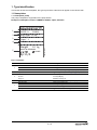
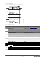
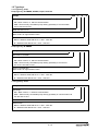
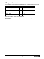
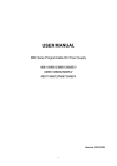
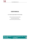
Service instructions
SQ, SQE, SQ-N
Model B
MS 3, MSE 3
Model B
50/60 Hz
1~
Table of contents
1.
Type identification ........................................................................................................................... 2
1.1
Nameplates........................................................................................................................................ 2
1.2
Type keys .......................................................................................................................................... 5
2.
Torques and lubricants ................................................................................................................... 6
3.
Service tools .................................................................................................................................... 7
3.1
Special tools ...................................................................................................................................... 7
3.2
Standard tools.................................................................................................................................... 7
3.3
Torque tools....................................................................................................................................... 7
4.
Dismantling and assembly ............................................................................................................. 8
4.1
General .............................................................................................................................................. 8
4.2
Separating and connecting pump and motor..................................................................................... 9
4.3
Replacement of hydraulic parts ....................................................................................................... 10
4.4
Checking the motor.......................................................................................................................... 11
4.5
Filling of motor liquid........................................................................................................................ 13
5.
Order of assembly ......................................................................................................................... 14
6.
Test specifications ........................................................................................................................ 18
96745261 0507
GB
19
1 / 19
1. Type identification
This section shows the nameplates, the type keys and the codes that can appear in the variant code.
1.1 Nameplates
1.1.1 Nameplate, pump
The pump nameplate is engraved into the pump sleeve.
Example of nameplate, Europe, S-AMREG, APREG, Japan, Australia
1
PROD.NO.
MODEL B
2
SQ/SQE 3-30
3
Q: 3 m3/h
Stages: 2
P2 motor
H: 26 m
Weight
1.0 kg
0.44 kW
MADE IN DENMARK
5
N2042
Rp 1 1/4
TM03 0018 3704
4
96080386
P1 0436
Key to nameplate
Pos.
1
2
3
4
5
Code
Description
PROD.NO. 96080386
MODEL B
P1 0436
SQ/SQE 3-30
Q: 3 m³/h
Product number
Pump generation
Production code - Bjerringbro (P1) + year/week code
Type designation, see 1.2.1 Type key, pump
Flow (Q) 3 [m³/h]
H: 26 m
Head (H) 26 [m]
Stages: 2
P2 motor 0.44 kW
Weight 1.0 kg
MADE IN DENMARK
Number of stages 2
Required input power pump 0.44 [kW]
Pump net weight in kg
Country of origin: Denmark
Misc. marks of approval: CE etc.
Type and size of connecting thread
Rp 1 1/4
2 / 19
Example of nameplate, N-AMREG
1
2
3
4
5
TM03 8370 1107
6
Key to nameplate:
Pos.
1
2
3
4
5
6
Code
Description
PROD. NO. 96160185
MODEL B/B
P1 0549
10 SQE - 240
Pump unit 96397413
NPT 1 ¼
Stages: 5
Q: 10 GPM
H: 267 ft
U: 200-240 V - 50/60 HZ
I: 7.9 A
P1: 1.55 kW
P2 motor 0.75 HP
CONT. DUTY 86°F
Weight 12.1 lb
MADE IN DENMARK
Product number
Pump/motor generation
Production code - Bjerringbro (P1) + year/week code
Type designation, see 1.2.1 Type key, pump
Type and size of connecting thread
Number of stages: 5
Flow (Q) 10 [GPM]
Head (H) 267 [ft]
Supply Voltage and frequenc
Current consumption
Required input power motor in kW
Required input power pump (P2) in hp
Pump net weight in pounds
Country of origin: Denmark
Misc. marks of approval: UL etc.
CAUTION:
Various warnings
WARNING:
3 / 19
1.1.2 Nameplate, motor
The motor nameplate is engraved into the motor sleeve.
6
Weight 3.2/7 kg/lb
MSE3NE
3
4
IP 68
150m
THERMALLY PROTECTED
MADE IN DENMARK
7
N2042
2
TM03 0016 3704
5
PROD.NO. 96511018
MODEL B P1 0436
U: 1 x 200-240 V - 50/60 Hz
P1: 1.02 kW
I: 5.2 A
P2: 0.70 kW
S1/40 C 0.15 m/s
IEC/EN 60034
Cl. 1
P2: 0.5 HP
SF 1.85 SF AMP 5.2
CONT. DUTY 104 F 0.5 ft/s
Ins. Cl. F
Code A
PF 1.0 RPM: 10700
1
Key to nameplate, motor
Pos.
1
2
Code
Description
MSE3NE
PROD.NO. 96511018
MODEL B
P1 0436
Type designation, see 1.2.2 Type key, motor
Product number
Motor generation
Production code – Bjerringbro (P1) + year/week code
IEC data
3
U: 1x200-240 V - 50/60 Hz
P1: 1.02 kW
I: 5.2 A
P2: 0.7 kW
S1/40C 0.15 m/s
Required electricity supply [V]
Input power [kW]
Input current [A]
Output power [kW].
Continuous operation up to 40°C, min. flow velocity
past the motor in m/s. Standard: IEC/EN 60034.
IEC/EN 60034 Cl. 1
N-AMREG data
P2 0.5 HP
SF 1.85 SF AMP 5.2
4
5
6
Output power (P2) in horse power
Service factor + max. ampere for a given SF
Suitable for continuous operation at 104°F and flow of
0.5 ft/s
Insulation class F. Start-kVA per hp
Power factor = 1. Rated speed 10,700 rpm
Motor net weight in kg and pounds
CONT. DUTY 104F 0.5 ft/s
Ins. CL. F Code A
PF 1.0 RPM 10700
Weight 3.2/7 kg/lb
Enclosure class: IP 68. Max installation depth: 150 m.
IP 68 150 m
7
THERMALLY PROTECTED
MADE IN DENMARK
Temperature sensor built into the electronic unit
Country of origin: Denmark
Misc. marks of approval: CE, etc.
4 / 19
1.2 Type keys
1.2.1 Type key, pump
Pump type key, S-AMREG, APREG, Japan, Australia
Example
SQE
2-
35
N
140
N
3-
N
Type range:
• SQ = Basic version, i.e. without communication.
• SQE = Electronically controllable pump offering possibility of communication
via CU 300 and CU 301.
Rated flow rate in m³/h.
Head in m at rated flow.
Note: Head is an approximated value.
Material code:
• Blank = Stainless steel DIN W.-Nr. 1.4301 - AISI 304.
• N = Stainless steel DIN W.-Nr. 1.4401 - AISI 316.
Pump type key, N-AMREG
Example
10
SQE -
Rated flow in US GPM.
Type range:
• SQ = Basic version, i.e. without communication.
• SQE = Electronically controllable pump offering possibility of communication via CU 300 and CU 301.
Head in ft at rated flow.
Note: Head is an approximated value.
Material code:
• Blank = Stainless steel DIN W.-Nr. 1.4301 - AISI 304.
• N = Stainless steel DIN W.-Nr. 1.4401 - AISI 316.
1.2.2 Type key, motor
Example
MSE
Type range:
• MS = Basic version, i.e. without communication.
• MSE = Electronically controllable pump offering possibility of communication via
CU 300 and CU 301.
Motor diameter: 3”.
Material code:
• Blank = Stainless steel DIN W.-Nr. 1.4301 - AISI 304.
• N = Stainless steel DIN W.-Nr. 1.4401 - AISI 316.
5 / 19
2. Torques and lubricants
This section shows the parts and nuts that must be tightened to a certain torque and the lubricants to be
used.
Pos.
Description
Number
Torque [Nm]
150
1a
Discharge chamber
1
220
End cover with cable
1
225
Top cover *)
1
232
Lip seal ring
1
250
Screw
4
1.0 +0.5
Pump
1
55
Lubricant
Unisilkon
Unisilkon
15±5
Unisilkon
Unisilkon
Grease, type Unisilkon, L 641, 5 g, part number 96037562.
*) It is not possible to do service on motors produced after week 6, 2006. It is only possible to dismantle
them for Analysing.
6 / 19
3. Service tools
A
B
C
D
E
F
G
H
I
J
K
L
M
N
O
3.1 Special tools
Pos.
Description
A
Key for discharge chamber
B
Protective clamps
C
Fitting tool for cone for pressure
equalization
D
Puller for metal top 2)
For pos.
Additional information
1a
Part no.
00SV0064
00SV0412
16-64-87
00SV2076
-
96617759
3.2 Standard tools
Pos.
Description
For pos.
Additional information
Part no.
E
Band pipe wrench
55
00SV0853
F
Ring/open-end spanner 1)
225
27 mm
00SV0084
G
Screwdriver (torx)
18b
T20
00SV0066
H
Nut driver with socket
250
00SV0065
I
Hook spanner 2)
D
00SV0241
3.3 Torque tools
Pos.
1
2
Description
J
Torque wrench
K
Torque screwdriver
L
For pos.
Additional information
Part no.
40-200 Nm
14x18
00SV0400
pos. L
1-6 Nm
1/4"
00SV0438
Adapter for torque screwdriver
pos. G
1/4" hexagon to 1/4"square
00SV0437
M
Open-end insert tool
pos. K
24 mm
14x18
00SV0624
N
Ring insert tool 1)
pos. K
27 mm
14x18
00SV0527
) Used only in connection with service operations on motors produced before week 6, 2006.
) Used only in connection with service operations on motors produced after week 5, 2006.
7 / 19
4. Dismantling and assembly
4.1 General
When the pump has been pulled out, possibly because it was running at reduced performance, it is important both to repair the pump and to check the submersible motor, please follow the instructions in the following sections.
Position numbers of parts (digits) refer to exploded views, sectional drawings and parts lists; position numbers of tools (letters) refer to section 3. Service tools.
4.1.1 Before dismantling
• Disconnect the electricity supply to the motor.
4.1.2 During dismantling
• When loosening the pump from the motor and from the discharge chamber, take care to apply counterpressure to the pump, see Fig. 1. This will prevent the pump or pump parts from being damaged,
bent or twisted.
4.1.3 Before assembly
• Clean and check all parts, especially the shaft with rotor due to magnetism. Citric acid is recommended for decalcifying.
• Check all parts for fractures and wear.
• Order the necessary service kits and/or parts.
• Replace defective parts by new parts.
4.1.4 During assembly
• Lubricate and/or tighten threads and rubber parts according to section 2. Torques and lubricants.
• When tightening the discharge chamber to the pump and the pump to the motor, take care to apply
counterpressure to the pump, see Fig. 1. This will prevent the pump or pump parts from being damaged, bent or twisted.
• Before connecting the pump to the motor, fill the motor with GRUNDFOS motor liquid SML 2, see
section 4.5 Filling of motor liquid.
4.1.5 After assembly
• The head and flow should be tested according to the test specifications, see section 6. Test specifications
Fig. 1. Apply counterpressure to the pump, when loosening the pump.
8 / 19
4.2 Separating and connecting pump and motor
4.2.1 Dismantling
PROD.NO. 96511018
MODEL B P1 0436
U: 1 x 200-240 V - 50/60 Hz
P1: 1.02 kW
I: 5.2 A
P2: 0.70 kW
MSE3NE
1. Slacken the screw (pos. 18b) and remove it together with the cable guard pos. 18.
2. If the motor is intact, the cable need not be removed. If the motor is defective, remove the Screws (pos.
250) and pull the end cover with cable and socket out of the motor.
A
TM03 3092 0206
3. Place the motor in a vice, using the two protective clamps pos. B.
Tighten only on the “A”-marked end of the motor according to table Fig. 3..
NOTE: Do not tighten “L”-marked part of the motor due to lack of support.
L
Fig. 2. Tighten area
Motor (P2)
[kW]
A
mm
L
mm
0.70
100
64
1.15
136
82
1.68-1.85
136
46
Fig. 3. Tighten area distance
4. Place a Band pipe wrench pos. E on the upper pump thread and loosen the pump by max. ½ turn
(right-hand thread). Do not remove the pump from the motor.
5. Slacken the vice. Stand the motor with pump upright with the motor uppermost and tighten the two
clamping faces of the discharge chamber in the vice.
6. Place the band pipe wrench on the pump thread close to the motor and loosen the pump (right-hand
thread).
7. Lift the motor with pump off the vice and place it on a plane surface.
8. Screw the pump off the motor.
4.2.2 Assembly
1. Place the motor in a vice, using the two Protective clamps pos. B.
Tighten only on the “A”-marked end of the motor according to table Fig. 3..
2. Pull the pump shaft a little out of the pump (approx. corresponding to the length of the coupling).
3. Apply a thin layer of grease to the spline inside the coupling and the thread on the motor.
4. Hold the coupling with your fingers and press the coupling home on the motor shaft.
5. Screw the pump home on the motor.
6. Turn motor and pump to a vertical position with the pump upwards and tighten the vice around the
thread below the suction strainer.
7. Using the Key for discharge chamber pos. A, the Open-end insert tool pos. M and the Torque wrenchpos. J tighten the discharge chamber to the sleeve.
8. Turn motor and pump to a horisontal position and place them in a vice, using the two Protective clamps
pos. B, see Fig. 2.Tighten area.
9. Using the Key for discharge chamber pos. A, the Open-end insert tool pos. M and the Torque wrench
pos. J tighten the pump to the motor.
10. Clean and apply a thin layer of grease to the end cover.
9 / 19
11. Push the end cover into the motor. Fit and tighten the screws pos. 250 using the Torque screwdriver
pos. K and the bit torx T20 from service tool pos. G .
12. Place the motor cable along the motor and the pump so that it lies flat.
13. Fit the cable guard over the cable. The two tabs of the cable guard must engage with the upper edge of
the pump sleeve. Fit the screw 18b and tighten it.
4.3 Replacement of hydraulic parts
4.3.1 Dismantling
1. Separate the pump from the motor, see section 4.2 Separating and connecting pump and motor.
2. Screw the discharge chamber out of the pump sleeve.
3. Shake the pump parts gently out of the top of the pump sleeve, and pull the pump shaft complete pos.
16 down and out of the pump sleeve.
If the pump parts are stuck, remove the cone for pressure equalization pos. 87.
4. Remove the cone by pressing the four projections (locks) on the cone that engage with the holes in the
pump sleeve at the same time as the cone is pressed down and out of the pump sleeve.
5. Press the parts out through the top of the pump sleeve using a punch.
6. If the parts of the valve casing complete, see “Parts list”, are defective, replace these parts. Prise the
retaining ring pos. 7a out of the recess of the discharge chamber pos. 1a and press the parts down and
out of the discharge chamber.
4.3.2 Assembly
1. Assemble the chamber stack.
• Before assembling the chamber stack, assemble the chamber parts into a unit: chamber complete,
see Fig. 4..
The chamber bottom pos. 9c can be accidentally separated, and if so, assemble it before assembling the chamber. The neck ring retainer should be pressed home in the chamber bottom.
In SQ 1, 2 and 3, make sure that the guide vanes pos. 32 engage with the bottom of the chamber.
SQ 5, 7
22, 30 SQ
SQ 1, 2, 3
5, 10, 15 SQ
9b
9b
32
9a
13
9a
9c
9c
TM01 3137 0402
13
Fig. 4. Assembly of chamber
• Fit the ring pos. 14a on the inlet part. Then place inlet part complete pos. 14 on a plane surface.
• Further assembly until the last chamber, see section 5. Order of assembly.
2. Fit the sleeve.
• Carefully turn the chamber stack so that the inlet part is pointing upwards.
• Turn the sleeve pos. 55 with the suction strainer upwards and carefully place it over the chamber
stack.
• Pull the sleeve with chamber stack so far out over the edge of the work top that the chamber stack
can be pushed home in the sleeve by hand.
• Turn the sleeve with chamber stack so the suction strainer is pointing downwards.
3. Fit the valve and discharge chamber.
• Place the valve casing complete on a plane surface with the bearing pos. 6 downwards.
10 / 19
• Lubricate the O-ring pos. 1d with grease and fit it in the outside recess of the valve casing.
• Press the discharge chamber pos. 1a over the valve casing. Turn the discharge chamber and fit the
retaining ring pos. 7a in the recess of the discharge chamber.
• Grease the discharge chamber with valve casing complete and screw it into the top of the sleeve.
4. Fit the pump shaft complete.
• Grease the lip seal ring pos. 86.
• Fit the pump shaft pos. 16 into the cone for pressure equalization complete pos. 87.
Take care not to damage the lip seal ring pos. 86.
• Turn the priming screw pos. 64 with the cylindrical part (without screw) upwards and fit it on the shaft.
• Place the cone for pressure equalization complete with shaft and priming screw on Fitting tool for
cone for pressure equalization pos. C. Then press sleeve with chamber stack down over the cone.
Make sure that the four projections of the cone engage with the holes in the sleeve.
• If necessary, turn the shaft till the splines engage with the impellers.
4.4 Checking the motor
It is not possible to dismantle motors produced after week 5, 2006
It is only possible to dismantle the motor for analysis, see 4.4.3 Analysing motors produced after week 5,
2006.
4.4.1 Dismantling
A
L
TM03 3093 0206
1. Place the motor in a vice, using the two protective clamps pos. B.
Tighten only on the “A”-marked end of the motor according to table Fig. 3.Tighten area distance.
NOTE: Do not tighten “L”-marked part of the motor due to lack of support.
Fig. 5. Tighten area.
Motor (P2)
[kW]
A
mm
L
mm
0.70
120
84
1.15
156
102
1.68-1.85
156
66
Fig. 6. Tighten area distance.
2. Prise off the filling plug pos. 222a.
Please note that the motor is full of liquid.
3. Screw the top cover (right-hand thread) out of the motor using the ring of the Ring/open-end spanner 1)
pos. F.
4. Due to the powerful magnetism of the shaft with rotor, hold the splined shaft end firmly and pull the
shaft with rotor and upper radial bearing pos. 205 out of the motor.
The thrust bearing pos. 203 may come out together with the shaft with rotor.
Check if the thrust bearing pos. 203 is in the motor.
4.4.2 Assembly
1. Fit the thrust bearing pos. 203 with the sliding surface uppermost carefully into the motor.
2. Turn the thrust bearing until its three dogs engage with the three notches at the bottom of the motor.
3. Fit the stop ring pos. 202a on the shaft with rotor with the sliding surface uppermost.
4. Turn the stop ring until the driving dogs engage with the shaft.
5. Hold the splined shaft end firmly due to magnetism and fit the shaft with rotor pos. 202 carefully into the
motor. The shaft with rotor must engage with the thrust bearing.
6. Check the shaft height, see Fig. 7.Motor shaft height.
11 / 19
TM032950 4905
Fig. 7. Motor shaft height
7. Fit the upper radial bearing pos. 205 carefully on the shaft with rotor and press it home in the recess of
the motor.
8. Apply a thin layer of grease to the O-ring pos. 224 and the lip seal ring pos. 232.
TM01 3136 0900
9. Tighten the top cover pos. 225 into the stator using the Ring insert tool 1) pos. N and the Torque
wrench pos. J.
Make sure that the cover is under the top of the motor, see Fig. 8., and that the axial play is between 0.3
and 1.3 mm.
Fig. 8. Make sure that the cover is under the top of the motor
10. Fill the motor with liquid, see section 4.5 Filling of motor liquid.
4.4.3 Analysing motors produced after week 5, 2006
1. Place the motor in a vice with the shaft end upwards.
2. Lubricate the thread of the motor with oil.
3. Screw the brass nut on the motor until the upper edge of the nut is flush with the top of the motor.
4. Fit the split cone, and tighten the screws.
Note: The split cone conical internally.
5. Tighten the nut against the split cone using the hook spanner (pos. I), and pull off the motor top.
6. Remove the motor top including the split cone when loose.
7. Unscrew the nut, and remove the motor from the vice.
8. Pour the motor liquid into a container. Make sure the rotor does not drop out.
12 / 19
4.5 Filling of motor liquid
1. Place the motor in vertical position with an inclination of approx. 10°.
2. Remove the filling plug using a screwdriver or a similar tool.
3. Inject motor liquid into the motor with a filling syringe or the like.
4. To allow possible air to escape, move the motor from side to side.
5. Refit the filling plug and make sure that it is tight.
6. The motor is now ready for installation. Fit the pump to the motor, see section 4.2.2 Assembly.
TM01 1434 4597
10
Fig. 9. Max tilt angel af the motor, when filling in motor liquid.
13 / 19
5. Order of assembly
1. Determine pump type and stage variant. Find the pump in the relevant stage survey table.
2. Find the components of each stage in the symbol survey.
1x
2x
1x
1x
1x
Example:
SQ/SQE 1-35(N)
5 SQ(N)/SQE 90
= pos. 1a
= pos. 9a
= pos. 4aSee drawing on page 16
= pos. 6, 7a, 1d, 1, 3, 2, 39, 70
= pos. 14
Stage survey
10
9
8
7
6
5
4
3
2
1
SQ / SQE 1 -
35
50
65
80
95
110
125
140
155
5 SQ / SQE 90
140
180
230
270
320
360
410
450
7
6
5
4
3
2
1
SQ / SQE 2 -
35
55
70
85
100
115
10 SQ / SQE 110
160
200
240
290
330
SQ / SQE 3 -
30
40
55
65
80
95
105
15 SQ / SQE 70
110
150
180
220
250
290
14 / 19
TM01 3068 0402
9
8
7
6
5
4
3
2
1
6
5
4
3
2
1
SQ / SQE 5 -
15
25
35
50
60
70
22 SQ / SQE 40
80
120
160
190
220
4
3
2
1
SQ / SQE 7 -
15
30
40
30 SQ / SQE 40
90
130
Symbol survey
70
39
2
3
1
1
1d
1d
7a
7a
9b
9b
32
9a
13
9a
13
6
6
1)
14
9c
4a
TM01 3069 0402
1a
9c
1)
Order of assembly
1)In case the pump has no valve (Austria), symbol
15 / 19
is used instead of
.
Example of order of assembly
SQ / SQE 1 - 35(N)
5 SQ / SQE 90
1a
70
39
2
3
1
1d
7a
6
55
4a
9b
18b
32
9a
9b
13
32
9c
64
18
9a
30
13
87
86
9c
TM03 2949 4905
14
16
16 / 19
Motor drawing
202b
222a
222a
225
232
224
205
202a
202b
202
203
201
220
250
250
Model B produced before week 6, 2006
Model B produced after week 5, 2006
17 / 19
TM01 2016 1400, TM03 8212 0807
220
6. Test specifications
SQ / SQE 1
Type
SQ1-35
5-SQ-90
SQ1-50
5-SQ-140
SQ1-65
5-SQ-180
SQ1-80
5-SQ-230
SQ1-95
5-SQ-270
SQ1-110
5-SQ-320
SQ1-125
5-SQ-360
SQ1-140
5-SQ-410
SQ1-155
5-SQ-450
Stage
2
3
4
5
6
7
8
9
10
Flow Pressure Pressure Pressure Nom. effect
m3/h min. mvs nom. mvs max. mvs P1/115V
0
43
46
50
590
1
31
34
36
0
65
70
76
810
1
48
53
56
0
87
94
101
1050
1
65
71
74
0
110
118
127
1
83
90
93
0
132
142
153
1
100
108
112
0
154
166
178
1
117
126
132
0
176
190
204
1
134
144
152
0
198
214
229
1
151
162
171
0
221
238
255
1
168
181
190
Amps Nom. effect Amps
115V
P1/230V
230V
5.10
580
2.50
7.00
780
3.30
9.00
1000
4.30
1180
5.10
1380
6.00
1590
7.00
1820
7.80
2020
8.6
2190
9.6
SQ / SQE 2
Type
SQ2-35
10-SQ-110
SQ2-55
10-SQ-160
SQ2-70
10-SQ-200
SQ2-85
10-SQ-240
SQ2-100
10-SQ-290
SQ2-115
10-SQ-330
Stage
2
3
4
5
6
7
Flow Pressure Pressure Pressure Nom. effect Amps Nom. effect
m3/h min. mvs nom. mvs max. mvs P1/115V
115V
P1/230V
0
41
44
49
730
6.30
710
2
32
35
38
0
62
68
74
1050
9.0
1000
2
50
54
59
0
81
88
96
1270
2
66
71
78
0
100
109
119
1550
2
81
88
96
0
121
132
143
1860
2
100
108
118
0
143
155
168
2110
2
119
128
139
Water temperature: 20-25°C
Max. testtime: 5 min
To be tested at nominal voltage an frequence
Flow adjusted to +/- 0.02
18 / 19
Amps
230V
3.00
4.30
5.50
6.80
8.00
9.30
SQ / SQE 3
Type
SQ3-30
15-SQ-70
SQ3-40
15-SQ-110
SQ3-55
15-SQ-150
SQ3-65
15-SQ-180
SQ3-80
15-SQ-220
SQ3-95
15-SQ-250
SQ3-105
15-SQ-290
Stage
2
3
4
5
6
7
8
Flow Pressure Pressure Pressure Nom. effect
m3/h min. mvs nom. mvs max. mvs P1/115V
0
32
35
39
730
3
23
26
28
0
51
55
61
1040
3
38
42
46
0
67
73
80
3
51
56
61
0
84
91
99
3
63
70
76
0
101
110
119
3
76
84
91
0
118
128
139
3
89
98
107
0
135
146
159
3
101
113
122
Amps Nom. effect Amps
115V
P1/230V
230V
6.20
700
2.30
8.90
990
4.20
1250
5.40
1520
6.70
1820
7.80
2090
9.00
2330
10.30
SQ / SQE 5
Type
SQ5-15
22-SQ-40
SQ5-25
22-SQ-80
SQ5-35
22-SQ-120
SQ5-50
22-SQ-160
SQ5-60
22-SQ-190
SQ5-70
22-SQ-220
Stage
1
2
3
4
5
6
Flow Pressure Pressure Pressure Nom. effect
m3/h min. mvs nom. mvs max. mvs P1/115V
0
16
18
20
540
5
9
11
13
0
33
36
40
960
5
20
23
26
0
49
53
59
5
31
36
40
0
65
71
77
5
43
48
53
0
81
88
96
5
54
61
66
0
97
106
115
5
65
73
81
Amps Nom. effect Amps
115V
P1/230V
230V
4.70
530
2.30
8.20
920
3.90
1290
5.60
1700
7.30
2080
8.90
2430
10.70
SQ / SQE 7
Type
SQ7-15
30-SQ-40
SQ7-30
30-SQ-90
SQ7-40
30-SQ-130
SQ7-55
30-SQ-170
Stage
1
2
3
4
Flow Pressure Pressure Pressure Nom. effect Amps Nom. effect
m3/h min. mvs nom. mvs max. mvs P1/115V
115V
P1/230V
0
19
20
23
750
6.40
730
7
6
9
12
0
38
42
46
1260
7
19
23
27
0
58
63
69
1810
7
32
37
42
0
72
78
84
2310
7
42
48
54
Water temperature: 20-25°C
Max. testtime: 5 min
To be tested at nominal voltage an frequence
Flow adjusted to +/- 0.02
19 / 19
Amps
230V
3.10
5.60
7.80
10.20