1
SPLIT-TYPE, HEAT PUMP AIR CONDITIONERS
November 2008
No. OC404
REVISED EDITION-A
TECHNICAL & SERVICE MANUAL
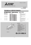
Series PFFY Floor Standing
Indoor unit
[Model names]
PFFY-P20VKM-E
PFFY-P25VKM-E
PFFY-P32VKM-E
PFFY-P40VKM-E
R410A
[Service Ref.]
PFFY-P20VKM-E
PFFY-P20VKM-ER1
PFFY-P25VKM-E
PFFY-P25VKM-ER1
PFFY-P32VKM-E
PFFY-P32VKM-ER1
PFFY-P40VKM-E
PFFY-P40VKM-ER1
R407C
R22
Revision:
• PFFY-P20/25/32/40
VKM-ER1 are added in
REVISED EDITION-A.
• Some descriptions have
been modified.
• Please void OC404.
CONTENTS
Indication of model name
INDOOR UNIT
NOTE:
This service manual describes technical data of the indoor units.
• As for outdoor units refer to outdoor unit’s service manual.
• RoHS compliant products have <G> mark on the spec name plate.
1. TECHNICAL CHANGES......................... 2
2. SAFETY PRECAUTION.......................... 2
3. PART NAMES AND FUNCTIONS.......... 6
4. SPECIFICATION..................................... 8
5. NOISE CRITERIA CURVES..................10
6. AIR OUTLET SELECTION.................... 11
7. OUTLINES AND DIMENSIONS............ 12
8. WIRING DIAGRAM............................... 13
9. REFRIGERANT SYSTEM DIAGRAM...... 14
10. TROUBLE SHOOTING......................... 15
11. DISASSEMBLY PROCEDURE............. 23
12. RoHS PARTS LIST............................... 28
1
TEHNICAL CHANGES
PFFY-P20VKM-E
PFFY-P25VKM-E
PFFY-P32VKM-E
PFFY-P40VKM-E
PFFY-P20VKM-ER1
PFFY-P25VKM-ER1
PFFY-P32VKM-ER1
PFFY-P40VKM-ER1
INDOOR CONTROLLER BOARD (I.B.) has been changed.
2
SAFETY PRECAUTION
CAUTIONS RELATED TO NEW REFRIGERANT
Cautions for units utilizing refrigerant R407C
Do not use the existing refrigerant piping.
Use liquid refrigerant to seal the system.
The old refrigerant and lubricant in the existing piping
contains a large amount of chlorine which may cause the
lubricant deterioration of the new unit.
If gas refrigerant is used to seal the system, the composition
of the refrigerant in the cylinder will change and performance
may drop.
Use “low residual oil piping”
Do not use a refrigerant other than R407C.
If there is a large amount of residual oil (hydraulic oil, etc.)
inside the piping and joints, deterioration of the lubricant
will result.
If another refrigerant (R22, etc.) is used, the chlorine in the
refrigerant may cause the lubricant deterioration.
Store the piping to be used indoors during
installation and both ends sealed until just
before brazing.
(Store elbows and other joints in a plastic bag.)
If dust, dirt, or water enters the refrigerant cycle,
deterioration of the oil and compressor trouble may result.
Use a vacuum pump with a reverse flow check valve.
The vacuum pump oil may flow back into the refrigerant
cycle and cause the lubricant deterioration.
Ventilate the room if refrigerant leaks during
operation. If refrigerant comes into contact with
a flame, poisonous gases will be released.
Use ESTR , ETHER or HAB as the lubricant to
coat flares and flange connection parts.
If large amount of mineral oil enter, that can cause
deterioration of refrigerant oil etc.
2
[1] Cautions for service
·After recovering the all refrigerant in the unit, proceed to working.
·Do not release refrigerant in the air.
·After completing the repair service, recharge the cycle with the specified amount of
liquid refrigerant.
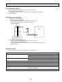
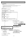
[2] Refrigerant recharging
(1) Refrigerant recharging process
1Direct charging from the cylinder.
·R407C cylinder are available on the market has a syphon pipe.
·Leave the syphon pipe cylinder standing and recharge it.
(By liquid refrigerant)
Unit
Gravimeter
(2) Recharge in refrigerant leakage case
·After recovering the all refrigerant in the unit, proceed to working.
·Do not release the refrigerant in the air.
·After completing the repair service, recharge the cycle with the specified amount of
liquid refrigerant.
[3] Service tools
Use the below service tools as exclusive tools for R407C refrigerant.
No.
1
Tool name
Specifications
Gauge manifold
·Only for R407C.
·Use the existing fitting SPECIFICATIONS. (UNF7/16)
·Use high-tension side pressure of 3.43MPa·G or over.
2
Charge hose
3
Electronic scale
·Only for R407C.
·Use pressure performance of 5.10MPa·G or over.
4
Gas leak detector
·Use the detector for R134a or R407C.
5
Adapter for reverse flow check.
·Attach on vacuum pump.
6
Refrigerant charge base.
7
Refrigerant cylinder.
8
Refrigerant recovery equipment.
·For R407C
·Top of cylinder (Brown)
·Cylinder with syphon
3
Cautions for units utilizing refrigerant R410A
Do not use the existing refrigerant piping.
Use a vacuum pump with a reverse flow check
valve.
The old refrigerant and lubricant in the existing piping
contains a large amount of chlorine which may cause the
lubricant deterioration of the new unit.
Vacuum pump oil may flow back into refrigerant cycle and
that can cause deterioration of refrigerant oil etc.
Use “low residual oil piping”
If there is a large amount of residual oil (hydraulic oil, etc.)
inside the piping and joints, deterioration of the lubricant
will result.
Use the following tools specifically designed for
use with R410A refrigerant.
The following tools are necessary to use R410A refrigerant.
Gauge manifold
Charge hose
Gas leak detector
Torque wrench
Store the piping to be used indoors during
installation and both ends of the piping sealed
until just before brazing. (Leave elbow joints, etc.
in their packaging.)
If dirt, dust or moisture enter into refrigerant cycle, that can
cause deterioration of refrigerant oil or malfunction of compressor.
Tools for R410A
Flare tool
Size adjustment gauge
Vacuum pump adaptor
Electronic refrigerant
charging scale
Handle tools with care.
If dirt, dust or moisture enter into refrigerant cycle, that can
cause deterioration of refrigerant oil or malfunction of compressor.
Use ester oil, ether oil or alkylbenzene oil (small
amount) as the refrigerant oil applied to flares
and flange connections.
Do not use a charging cylinder.
If large amount of mineral oil enter, that can cause deterioration of refrigerant oil etc.
If a charging cylinder is used, the composition of refrigerant will change and the efficiency will be lowered.
Charge refrigerant from liquid phase of gas
cylinder.
If the refrigerant is charged from gas phase, composition
change may occur in refrigerant and the efficiency will be
lowered.
Ventilate the room if refrigerant leaks during
operation. If refrigerant comes into contact with
a flame, poisonous gases will be released.
Do not use refrigerant other than R410A.
If other refrigerant (R22 etc.) is used, chlorine in refrigerant can cause deterioration of refrigerant oil etc.
4
[1] Cautions for service
(1) Perform service after collecting the refrigerant left in unit completely.
(2) Do not release refrigerant in the air.
(3) After completing service, charge the cycle with specified amount of refrigerant.
(4) When performing service, install a filter drier simultaneously.
Be sure to use a filter drier for new refrigerant.
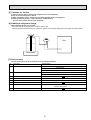
[2] Additional refrigerant charge
When charging directly from cylinder
· Check that cylinder for R410A on the market is syphon type.
· Charging should be performed with the cylinder of syphon stood vertically. (Refrigerant is charged from liquid phase.)
Unit
Gravimeter
[3] Service tools
Use the below service tools as exclusive tools for R410A refrigerant.
No.
1
Tool name
Specifications
Gauge manifold
·Only for R410A
·Use the existing fitting specifications. (UNF1/2)
·Use high-tension side pressure of 5.3MPa·G or over.
2
Charge hose
·Only for R410A
·Use pressure performance of 5.09MPa·G or over.
3
Electronic scale
4
Gas leak detector
·Use the detector for R134a, R407C or R410A.
5
Adaptor for reverse flow check
·Attach on vacuum pump.
6
Refrigerant charge base
7
Refrigerant cylinder
·Only for R410A
Top of cylinder (Pink)
Cylinder with syphon
8
Refrigerant recovery equipment
5
3
PART NAMES AND FUNCTIONS
Indoor Unit
Louver
Air inlet
Air outlet
Vane
Filter
Damper
Air outlet
Louver
Wired remote controller
Once the controls are set, the same operation mode can be repeated by simply pressing the ON/OFF button.
Operation buttons
ON/OFF button
Set Temperature buttons
Down
Fan Speed button
Up
Timer Menu button
(Monitor/Set button)
Filter
button
(<Enter> button)
Mode button (Return button)
TEMP.
ON/OFF
Set Time buttons
Check button (Clear button)
Back
Ahead
Timer On/Off button
(Set Day button)
Test Run button
MENU
BACK
PAR-21MAA
MONITOR/SET
ON/OFF
FILTER
DAY
CHECK TEST
OPERATION
CLOCK
Airflow Up/Down button
CLEAR
Louver button
(
Operation button)
To preceding operation
number.
Opening the
door.
Ventilation button
Operation button)
(
To next operation number.
6
Display
“Sensor” indication
For purposes of this explanation,
all parts of the display are shown
as lit. During actual operation, only
the relevant items will be lit.
Displayed when the remote controller
sensor is used.
Day-of-Week
Shows the current day of the week.
Time/Timer Display
“Locked” indicator
Shows the current time, unless the simple or Auto Off
timer is set.
If the simple or Auto Off timer is set, shows the time
remaining.
Indicates that remote controller buttons have been locked.
Identifies the current operation
“Clean The Filter” indicator
Shows the operating mode, etc.
* Multilanguage display is supported.
Comes on when it is time to clean the
filter.
TIME SUN MON TUE WED THU FRI SAT
TIMER
Hr
ON
AFTER
“Centrally Controlled” indicator
The indicator comes on if the corresponding timer is set.
FUNCTION
FILTER
°F°C
°F°C
Indicates that operation of the remote controller has been prohibited by a master controller.
Timer indicators
AFTER OFF
ERROR CODE
WEEKLY
SIMPLE
AUTO OFF
ONLY1Hr.
Fan Speed indicator
Shows the selected fan speed.
“Timer Is Off” indicator
Indicates that the timer is off.
Temperature Setting
Shows the target temperature.
Room Temperature display
Up/Down Air Direction indicator
Ventilation indicator
Shows the room temperature.
Appears when the unit is running in
Ventilation mode.
The indicator
shows the direction of the outcoming airflow.
Louver display
“One Hour Only” indicator
Indicates the action of the swing
louver. Does not appear if the
louver is stationary.
Displayed if the airflow is set to
Low and downward during COOL
or DRY mode. (Operation varies
according to model.)
The indicator goes off after one
hour, at which time the airflow direction also changes.
(Power On indicator)
Indicates that the power is on.
Caution
Only the Power on indicator lights when the unit is stopped and power supplied to the unit.
If you press a button for a feature that is not installed at the indoor unit, the remote controller will display the “Not Available”
message.
If you are using the remote controller to drive multiple indoor units, this message will appear only if he feature is not
present at every unit connected.
When power is turned ON for the first time, it is normal that “PLEASE WAIT” is displayed on the room temperature indication
(For max. 2minutes). Please wait until this “PLEASE WAIT” indication disappear then start the operation.
For the PFFY-P VKM series, the airflow direction displayed on the remote controller is different from the actual airflow direction. Refer to the following table.
1
(Horiz.)
2
3
4
Swing
Display
1
2
3
4
(Horiz.)
Swing
Actual
The airflow direction for the lower air outlet damper cannot be set. The airflow direction is automatically controlled by a computer.
7
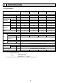
4
SPECIFICATION
4-1. Specification
PFFY-P25VKM-E
PFFY-P32VKM-E
PFFY-P40VKM-E
PFFY-P20VKM-E
PFFY-P20VKM-ER1 PFFY-P25VKM-ER1 PFFY-P32VKM-ER1 PFFY-P40VKM-ER1
Item
Power source
1-phase 220-240V 50Hz
Cooling capacity
kW
2.2
2.8
3.6
4.5
Heating capacity
kW
2.5
3.2
4.0
5.0
Power
Cooling
kW
0.025
0.025
0.025
0.028
consumption
Heating
kW
0.025
0.025
0.025
0.028
Cooling
A
0.20
0.20
0.20
0.24
Heating
A
0.20
0.20
0.20
0.24
Height
mm
600
600
600
600
Width
mm
700
700
700
700
Depth
mm
200
200
200
200
kg
15
15
15
15
Current
Dimension
Weight
Cross fin (Aluminum plate fin and copper tube)
Heat exchanger
Type
Fan
Line flow fan % 2
Airflow rate *2
External static
pressure
Motor
m /min
3
5.9-6.8-7.6-8.7
6.1-7.0-8.0-9.1
6.1-7.0-8.0-9.1
Pa
8.0-9.0-9.5-10.7
0
Type
DC motor
Output
kW
0.03 % 2
Air filter
PP honeycomb fabric (Catechin air filter)
Refrigerant
Gas (Flare)
: mm
:12.7
pipe dimension
Liquid (Flare)
: mm
:6.35
Field drain pipe size
: mm
I.D.16(PVC pipe VP-16 connectable)
Noise level *2
dB(A)
27-31-34-37
28-32-35-38
Note 1. Rating conditions (JIS B 8616)
Cooling :Indoor : D.B. 27°C W.B. 19.0°C
outdoor :D.B. 35°C
Heating :
Indoor : D.B. 20°C
outdoor :D.B. 7°C
W.B. 6°C
*2. Air flow and the noise level are indicated as High-Medium1-Medium2-Low.
8
28-32-35-38
35-38-42-44
4-2. Electrical parts specifications
Model
Symbol
Parts name
Thermistor
(Room temperature
detection)
Thermistor
(Pipe temperature
detection/Liquid)
Thermistor
(Pipe temperature
detection/Gas)
Fuse
(Indoor controller board)
PFFY-P20VKM-E
PFFY-P20VKM-ER1
PFFY-P25VKM-E
PFFY-P25VKM-ER1
PFFY-P32VKM-E
PFFY-P32VKM-ER1
PFFY-P40VKM-E
PFFY-P40VKM-ER1
TH21
Resistance 0/15k, 10/9.6k, 20/6.3k, 25/5.4k, 30/4.3k, 40/3.0k
TH22
Resistance 0/15k, 10/9.6k, 20/6.3k, 25/5.4k, 30/4.3k, 40/3.0k
TH23
Resistance 0/15k, 10/9.6k, 20/6.3k, 25/5.4k, 30/4.3k, 40/3.0k
FUSE
250V 6.3A
Fan motor (Upper)
MF1
OUTPUT 30W
ARW40Z8P30MS
Fan motor (Lower)
MF2
OUTPUT 30W
ARW40Y8P30MS
Vane motor
MV1
MP20Z
DC12V
Damper motor
MV2
MP35EA
DC12V
Linear expansion valve
[coil]
LEV
DC12V Stepping motor drive Port dimension :5.2 (0~2000 pulse)
EFM-40YGME
Power supply terminal
block
TB2
(L, N, ) 330V 30A
Transmission terminal
block
TB5
(M1, M2, S) 250V 20A
9
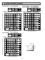
5
NOISE CRITERIA CURVES
PFFY-P20VKM-ER1
FAN SPEED FUNCTION
High
SPL(dB(A))
COOLING
37
HEATING
37
PFFY-P25VKM-E
PFFY-P32VKM-E
High
OCTAVE BAND SOUND PRESSURE LEVEL, dB re 0.0002 MICRO BAR
Test conditions,
Cooling : Dry-bulb temperature 27Wet-bulb temperature 19
Heating : Dry-bulb temperature 20Wet-bulb temperature 15
90
80
70
NC-70
60
NC-60
50
NC-50
40
NC-40
30
NC-30
20
10
APPROXIMATE
THRESHOLD OF
HEARING FOR
CONTINUOUS
NOISE
63
NC-20
125
250
500
1000
2000
4000
SPL(dB(A))
COOLING
38
HEATING
38
8000
80
70
NC-70
60
NC-60
50
NC-50
40
NC-40
30
NC-30
20
10
APPROXIMATE
THRESHOLD OF
HEARING FOR
CONTINUOUS
NOISE
63
125
NC-20
250
500
1000
2000
High
SPL(dB(A))
COOLING
44
HEATING
44
LINE
OCTAVE BAND SOUND PRESSURE LEVEL, dB re 0.0002 MICRO BAR
Test conditions,
Cooling : Dry-bulb temperature 27Wet-bulb temperature 19
Heating : Dry-bulb temperature 20Wet-bulb temperature 15
90
80
70
NC-70
INDOOR UNIT
60
MICROPHONE
NC-60
50
1m
NC-50
40
NC-40
30
NC-30
20
10
APPROXIMATE
THRESHOLD OF
HEARING FOR
CONTINUOUS
NOISE
63
125
NC-20
250
500
1000
2000
4000
4000
BAND CENTER FREQUENCIES, Hz
PFFY-P40VKM-ER1
FAN SPEED FUNCTION
LINE
Test conditions,
Cooling : Dry-bulb temperature 27Wet-bulb temperature 19
Heating : Dry-bulb temperature 20Wet-bulb temperature 15
90
BAND CENTER FREQUENCIES, Hz
PFFY-P40VKM-E
PFFY-P25VKM-ER1
PFFY-P32VKM-ER1
FAN SPEED FUNCTION
LINE
OCTAVE BAND SOUND PRESSURE LEVEL, dB re 0.0002 MICRO BAR
PFFY-P20VKM-E
8000
BAND CENTER FREQUENCIES, Hz
10
WALL
1m
8000
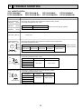
6
AIR OUTLET SELECTION
CN43
SWC
SW1
ON
OFF
CN82
1 2 3 4 5 6 7 8 9 10
7 8
4
5 6
7 8
2 3
2 3
4
5 6
(10ths DIGIT)
SWC
0 1
SW14
D
9
E
F0 1 2
BC
0 1
3456
9
SW11
789A
SW12
With this function, air comes out simultaneously from the upper and
lower air outlets so that the room can be cooled or heated effectively.
This function is set using the switch SWC on the address board.
./
.
(BRANCH No.)
(1s DIGIT)
Fig. 4-1
SWC
SWC
How to set to blow out air from the upper and lower air outlets:
Set the SWC to lower side (" "). (Initial setting)
Air blows out automatically from the upper and lower air outlet as
shown in the table below.
How to set to blow out air from the upper air outlet only:
Set the SWC to upper side (" ").
Note:
Be sure to operate with the main power turned off.
Description of operation
Operation
DRY
COOL
HEAT
FAN
Air flow
Upper and lower air flow
Upper air flow
Room temperature and Room temperature is
Conditions set temperature are dif- close to set temperature
ferent. +1
or thermo-off.+1
Upper air flow only
—
Upper and lower air flow
Upper air flow
During defrosting op(Normal condition (in
eration, start of operaheating))
tion, thermo-off
• Be sure to keep the area around the damper of the lower air outlet free of any objects.
+1
Upper and lower air flow
Upper air flow
2deg
4deg +2
+2
DIP SW3-2 (on indoor controller board) : OFF (Initial Setting)
If the air conditioner has operated for 2hours with upper and lower air flow,
it changes to 8deg for next 30minutes. After 30minutes it changes back to 4deg.
DIP SW3-2 (on indoor controller board) : ON
Remains to be 4deg.
11
(Room temp. – Set temp.)
Upper and lower air flow
—
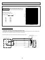
7
OUTLINES AND DIMENSIONS
PFFY-P20VKM-E
PFFY-P25VKM-E
PFFY-P32VKM-E
PFFY-P40VKM-E
PFFY-P20VKM-ER1
PFFY-P25VKM-ER1
PFFY-P32VKM-ER1
PFFY-P40VKM-ER1
Unit : mm
INDOOR UNIT
131
131
7
4-:6 Hole
593
333
363
Installation plate
Indoor unit
700
607
210
46.5
600
Air in
96
Gas pipe
:12.7(flared)1/2
Liquid pipe
:6.35(flared)1/4
12
11
508
drain
137
60
155
454
128
45
35
72
110
60
123
54
147
12
60
60
19
125
60
Air out
118
60
80
12
165
205
More than
100mm
337
125
More than
100mm
200
12
12
Air out
19
More than
100mm
46.5
337
8
WIRING DIAGRAM
PFFY-P20VKM-E
PFFY-P25VKM-E
PFFY-P32VKM-E
PFFY-P40VKM-E
PFFY-P20VKM-ER1
PFFY-P25VKM-ER1
PFFY-P32VKM-ER1
PFFY-P40VKM-ER1
[LEGEND]
SYMBOL
I. B
CN32
CN51
CN52
SW2
SW3
SW4
ZNR
FUSE
LED1
LED2
NAME
INDOOR CONTROLLER BOARD
CONNECTOR REMOTE SWITCH
CENTRALLY CONTROL
REMOTE INDICATION
SWITCH
CAPACITY CODE
MODE SELECTION
MODEL SELECTOR
VARISTOR
FUSE (T6.3AL250V)
POWER SUPPLY (I.B)
POWER SUPPLY (I.B)
SYMBOL
MF1
MF2
MV1
MV2
LS
LEV
TB2
TB5
TH21
NAME
SYMBOL
NAME
FAN MOTOR (UPPER)
PIPE TEMP. DETECTION/GAS
TH23
FAN MOTOR (LOWER)
(0/15k, 25/5.4k)
A. B
VANE MOTOR
ADDRESS BOARD
SW1 SWITCH
DAMPER MOTOR
MODE SELECTION
SW11
DAMPER LIMIT SWITCH (CLOSE)
ADDRESS SETTING 1s DIGIT
SW12
LINEAR EXPANSION VALVE
ADDRESS SETTING 10ths DIGIT
SW14
TERMINAL POWER SUPPLY
BRANCH NO.
BLOCK
SWC
TRANSMISSION
AIR OUTLET SELECTION
THERMISTOR ROOM TEMP. DETECTION
(0/15k, 25/5.4k)
PIPE TEMP. DETECTION/LIQUID
(0/15k, 25/5.4k)
TH22
NOTES
1. At servicing for outdoor unit, always follow the wiring diagram of outdoor unit.
2. In case of connecting MA-Remote controller, please connect MA remote controller cable
in an accessory to the connecter 1 2 . (Remote controller wire is non-polar.)
3. In case of using M-NET, please connect to TB5. (Transmission line is non-polar.)
4. Symbol [S] of TB5 is the shield wire connection.
5. Symbols used in wiring diagram above are,
: terminal block,
: connector.
6. The setting of the SW2 dip switches differs in the capacity. For the detail, refer to fig. + 1.
<fig. + 1>
LED on indoor board for service
MODELS
MEANING
FUNCTION
Main power supply (Indoor unit: 220-240V)
LED1 Main power supply
power on → Iamp is Iit
Power supply for
Power supply for MA-remote controller
LED2 MA-Remote controller on → Iamp is lit
MARK
TH21 TH23 TH22
LEV
LS
SW2
P20
ON
OFF
P25
ON
OFF
P32
ON
OFF
P40
ON
OFF
123456
123456
123456
123456
6
I.B
3 2 1
6 5 4 3 2 1
4 3 2 1
3 2 1
CN31
(WHT)
CN60
(WHT)
CN44
(WHT)
CN36
(BLK)
2 1
TO MA-REMOTE
CONTROLLER
DC8.7-13V
ORN
1 ORN
2
BLU
PNK
YLW
ORN
RED
BRN
TO OUTDOOR UNIT
TB5
M1
BC CONTROLLER
REMOTE CONTROLLER
M2
DC24-30V
S(SHIELD)
BLU
PNK
YLW
ORN
RED
BRN
1 2 3 4 5 6
1 2 3 4 5 6
See fig:+1
MV2
13
MV1
BRANCH
NO.
10ths 1s
DIGIT DIGIT
BLU
BLU
SWC SW14
0
ON
OFF
CN6V1
(GRN)
1 2 3 4 5 6 1 2 3 4 5 6
CN82
(RED)
CN6V2
(BLU)
CN43
(RED)
12345678910
1 2 3
4 3 2 1
SW1
1 2
8 7 6 5 4 3 2 1
ON
OFF
CN2M CN3A
(BLU) (BLU)
SW2
CNMF2
(WHT)
12345678910
2 1
CND
(BLK)
CN42
(RED) 4 3 2 1
LED2
ON
OFF
BLU
GRN/YLW
8 6 4 2
7 5 3 1
TB2 RED
CN32
(WHT)
SW3
CNMF1
(WHT)
BLK
4
A.B
ON
OFF
ZNR
BLK
WHT
BRN
BLU
8
SW12 SW11
0
0
SW4
DC311
~339V
FUSE
RED
L
N
CN81
(RED)
12345
SWE
BLK
WHT
BRN
BLU
ON
OFF
6 5 4 3 2 1
POWER SUPPLY
220-240V
50Hz
RED
1 2 3 4 5
MF1
6 5 4 3 2 1
MF2
1 2 3 4 5 6 7 8
CN52
CN51 (GRN)
(WHT)
CN20
(WHT)
123456
LED1
9
REFRIGERANT SYSTEM DIAGRAM
PFFY-P20VKM-E
PFFY-P25VKM-E
PFFY-P32VKM-E
PFFY-P40VKM-E
PFFY-P20VKM-ER1
PFFY-P25VKM-ER1
PFFY-P32VKM-ER1
PFFY-P40VKM-ER1
Thermistor (Pipe temperature detection/Gas) TH23
Strainer (#50mesh)
Gas pipe
Thermistor (Pipe temperature
detection/Liquid) TH22
Flare connection
Liquid pipe
Linear expansion valve
Strainer1 (#50mesh)
Strainer2 (#50mesh)
Strainer (#100mesh)
Thermistor (Room temperature detection) TH21
Heat exchanger
Unit: mm
Capacity
Item
PFFY-P20,P25,P32,P40VKM-E(R1)
Gas pipe
:12.7(1/2'')
Liquid pipe
:6.35(1/4'')
14
10
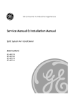
TROUBLE SHOOTING
10-1. HOW TO CHECK
PFFY-P20VKM-E
PFFY-P32VKM-E
PFFY-P20VKM-ER1
PFFY-P32VKM-ER1
PFFY-P25VKM-E
PFFY-P25VKM-ER1
Parts name
Check points
Room temperature
thermistor
(TH21)
Liquid pipe temperature
thermistor
(TH22)
Gas pipe temperature
thermistor
(TH23)
Fan motor (MF1,2)
Linear expansion
Blue
valve (LEV)
M
PFFY-P40VKM-E
PFFY-P40VKM-ER1
Disconnect the connector then measure the resistance using a tester.
(Surrounding temperature 10~30)
Normal
Abnormal
4.3k~9.6k
Open or short
Check 10-2.
Disconnect the connector then measure the resistance valve using a tester.
(Surrounding temperature 20)
Normal
Brown
Yellow
(Refer to the next page for a detail.)
(1)-(5)
White-Red
Abnormal
(2)-(6)
(3)-(5)
Yellow-Brown Orange-Red
(4)-(6)
Blue-Brown
200 $10%
White Red Orange
Vane motor (MV1)
Red
M
Yellow
Measure the resistance between the terminals using a tester.
(Surrounding temperature 20~30)
Connector
Brown — Orange
Brown
Orange Green
Normal
Abnormal
282~306
Open or short
Brown — Red
Brown — Yellow
Brown — Blue
Damper motor (MV2)
Orange
Red
Pink
M
Measure the resistance between the terminals using a tester.
(Surrounding temperature 20~30)
Connector
Abnormal
186~214
Open or short
Brown — Yellow
Brown — Blue
Red — Orange
Yellow Brown Blue
Normal
Red — Pink
15
Open or short
(Refer to the next
page for a detail.)
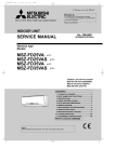
<Thermistor Characteristic graph>
Thermistor for
lower temperature
< Thermistor for lower temperature >
50
Room temperature thermistor (TH21)
Liquid pipe temperature thermistor (TH22)
Gas pipe temperature thermistor (TH23)
40
Rt=15exp { 3480( 1
273+t
0:
10:
20:
25:
30:
40:
Resistance (K)
Thermistor R0=15k' ± 3%
Fixed number of B=3480 ± 2%
1 )}
273
15k'
9.6k'
6.3k'
5.2k'
4.3k'
3.0k'
30
20
10
0
-20
-10
0
10 20 30
Temperature ()
40
50
Linear expansion valve
1 Operation summary of the linear expansion valve.
• Linear expansion valve open/close through stepping motor after receiving the pulse signal from the indoor controller board.
• Valve position can be changed in proportion to the number of pulse signal.
<Connection between the indoor controller board and the linear expansion valve>
Controller board
DC12V
Linear expansion valve
4
M
6
5
2
1
White Red
3
Orange
Blue
Brown
6
Red
5
Drive circuit
Brown
:4
Blue
4
:4
Yellow
:3
Orange
3
:3
:2
Yellow
2
:2
:1
White
1
:1
Connector (CN60)
16
<Output pulse signal and the valve operation>
Output
(Phase)
Output
1
2
3
4
{1
ON
OFF
OFF
ON
{2
ON
ON
OFF
OFF
{3
OFF
ON
ON
OFF
{4
OFF
OFF
ON
ON
Closing a valve : 1 → 2 → 3 → 4 → 1
Opening a valve : 4 → 3 → 2 → 1 → 4
The output pulse shifts in above order.
• When linear expansion valve operation stops, all output phase
become OFF.
• At phase interruption or when phase does not shift in order,
motor does not rotate smoothly and motor locks and vibrates.
2 Linear expansion valve operation
C
D
Valve position (capacity)
• When the switch is turned on, 2200 pulse closing valve signal
will be send till it goes to A point in order to define the valve
position.
• When the valve move smoothly, there is no noise or vibration
occurring from the linear expansion valve : however, when the
pulse number moves from E to A or when the valve is locked,
more noise can be heard than normal situation.
• Noise can be detected by placing the ear against the screw driver handle while putting the screw driver to the linear expansion
valve.
Close
Open
A
E
Outdoor unit
R410A model: 1400 pulse
R22 model : 2000 pulse
Opening a valve
all the way
Pulse number
B
Extra tightning (80~100pulse)
3 Trouble shooting
Symptom
Operation circuit
failure of the
micro processor.
Countermeasures
Check points
Disconnect the connector on the controller board,
then connect LED for checking.
1 LED
6
5
4
3
2
1
Exchange the indoor
controller board at drive
circuit failure.
Pulse signal will be sent out for 10 seconds as soon as
the main switch is turned on. If there is LED with lights
on or lights off, it means the operation circuit is abnormal.
Linear expansion
valve mechanism
is locked.
Short or breakage of
the motor coil of
the linear expansion valve.
Valve does not
close completely.
Motor will idle and make ticking noise when motor is
Exchange the linear
operated while the linear expansion valve is locked. This expansion vale.
ticking sound is the sign of the abnormality.
Measure the resistance between the each coil (red-white, Exchange the linear
red-orange, brown-yellow, brown-blue) using a tester. It expansion valve.
is normal if the resistance is in the range of 150'±10%.
To check the linear expansion valve, operate the indoor unit
in fan mode and at the same time operate other indoor units
in cooling mode, then check the pipe temperature <liquid
pipe temperature> of the indoor unit by the
outdoor multi controller board operation
monitor. During fan operation, linear expanLiquid pipe sion valve is closed completely and if there
thermistor are some leaking, detecting temperature of
the thermistor will go lower. If the detected
Linear
expansion
temperature is much lower than the temvalve
perature indicated in the remote controller,
it means the valve is not closed all the way.
It is not necessary to exchange the linear expansion valve, if
the leakage is small and not making any trouble.
Wrong connection Check the color of lead wire and missing terminal of
of the connector the connector.
or contact failure.
17
If large amount of
refrigerant is leaked,
exchange the linear
expansion valve.
Disconnect the connector at the controller
board, then check the
continuity.
10-2. FAN MOTOR
Check method of indoor fan motor (fan motor/control P.C.board)
Notes
· High voltage is applied to the connecter (CNMF1) for the fan motor. Pay attention to the service.
· Do not pull out the connector (CNMF1,2) for the motor with the power supply on.
(It causes trouble of the control P.C.board)
Self check
Conditions : The indoor fan cannot turn around.
Wiring contact check
Contact of fan motor connector (CNMF1,2)
N0
Was contact caused good?
Wiring recovery
Yes
Power supply check
Check the voltage in the indoor control P.C.board
TEST POINT
FAN MOTOR (upper)
CNMF1 CNMF2 : DC310 ~ 340V
CNMF2 : DC15V
CNMF2 : DC0 ~ 6.5V
FAN MOTOR (lower)
CNMF1 CNMF2 : DC310 ~ 340V
CNMF2 : DC15V
CNMF2 : DC0 ~ 6.5V
The voltage between CNMF2 and are values during the
fan motor operation. In the case that the fan motor off, the voltage is 0V.
Is the voltage normal?
Indoor controller board fuse check
No
Yes
No
Is the fuse normal?
Replace
the fuse.
Yes
Replace the indoor
controller board.
OK
NG
Check the operation
OK
Check the operation
Fan motor position sensor signal check
Turn around the fan motor more than one revolution slowly,
and check the voltage between the connecter
FAN MOTOR (upper)
CNMF2 /FAN MOTOR (lower) CNMF2 NG
Replace the fan motor.
No
Does the voltage repeat
DC 0V and DC 15V?
Replace the fan motor.
Yes
Yes
OK
Check the operation of fan.
Replace the indoor
controller board.
NG
Replace the indoor controller board.
OK
Check the operation
END
END
NG
Replace the fan motor.
18
END
END
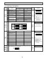
10-3. FUNCTION OF DIP SWITCH
Switch Pole
SW1
Function
setting
Operation by switch
Function
ON
OFF
Effective
timing
Remarks
1
Thermistor <Room temperature
detection> position
Built-in remote controller
Indoor unit
2
Filter clogging detection
Provided
Not provided
3
Filter cleaning
2,500hr
100hr
4
Fresh air intake
Effective
Not effective
5
Switching remote
controller display
Indicating if the
thermostat is ON
Indicating fan operation
ON/OFF
6
Humidifier control
7
Low +3
Extra low +3
+2 Thermo ON operation at
8
Air flow set in case of
Heat thermostat OFF
Setting air flow +3
Depends on SW1-7
+3 SW 1-7=OFF, SW 1-8=ON
9
Auto restart function
Effective
Not effective
Power ON/OFF by breaker
Effective
Not effective
10
Address board
<Initial setting>
ON
OFF
1 2 3 4 5 6 7 8 9 10
Note :
Under
+1 Fan operation at Heating
Always operated while the heat in ON +1 Operated depends on the condition +2 suspension
mode.
heating mode.
→ Setting air flow.
SW 1-7=ON, SW 1-8=ON
→ Indoor fan stop.
Indoor controller board
Capacity
SW2
Capacity
1~6
code
setting
SW3
Function
setting
P20
P25
SW 2
ON
OFF
ON
OFF
Capacity
P32
1 2 3 4 5 6
P40
1 2 3 4 5 6
Set while the unit is off.
SW 2
ON
OFF
ON
OFF
Before
power
supply
ON
1 2 3 4 5 6
<Initial setting>
Set for each capacity.
1 2 3 4 5 6
1
Heat pump/Cooling only
Cooling only
Heat pump
2
Limitation at time of damper
open operation + 4
Not effective
Effective
Indoor controller board
Set while the unit is off.
<Initial setting>
3
Vane
Available
Not available
4
Vane swing function
Available
Not available
5
Vane horizontal angle
Second setting +7
First setting
6
Vane cooling limit angle setting +5 Horizontal angle
7
Changing the opening of linear
expansion valve during thermo OFF
Effective
Not effective
8
Heat 4degrees up
Not effective
Effective
9
Superheat setting temperature +6
—
—
10
Sub cool setting temperature +6
—
—
Down B, C
1 2 3 4 5 6 7 8 9 10
Under
Note :
suspension +4 Refer to "6. AIR OUTLET
SELECTION"
In case replacing the indoor controller board, make sure to set the switch to the
SW4
factory-preset status, which is shown below.
Model
Selection
ON
(Setting 1~5
OFF
for
PFFY
1 2 3 4 5
series)
19
ON
OFF
+5 At cooling mode, each angle
can be used only 1 hour.
+6 Please do not use
SW3-9,10.
+7 Second setting is the same
as first setting.
Indoor controller board
Before
power
supply
ON
Effective
timing
Operation by switch
Switch Pole
Remarks
Address board
SWC
Air
outlet
selector
<Initial setting>
(Option)
2
Refer to 6. AIR OUTLET SELECTION.
(Standard)
Option
Standard
789A
Setting by connector
SWE
No function
Please do not change the setting to SWE.
ON
OFF
20
78
SW14
F01
45 6
Connector
<Initial setting>
23
How to set branch number SW14 (Series R2 only)
Match the indoor unit’s refrigerant pipe with the BC
contoller’s end connection number
Remain other than series R2 at "0".
Address board
BCDE
BCDE
F01
90 1
78
78
78
SW14
SW11
90 1
23
Before
power
supply
ON
SW12
23
Rotary switch
45 6
45 6
1
45 6
Rotary switch
23
10
How to set address
Example : If address is "3", remain SW12
(for over 10) at "0", and match SW11 (for 1 to 9)
with "3".
789A
90 1
45 6
SW11
90 1
Address can be set while the
unit is stopped.
<Initial setting>
45 6
SW12
23
SW14
Branch
No.
setting
Address board
23
SW11
1s digit
address
setting
SW12
10ths digit
address
setting
Remarks
Indoor controller board
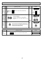
10-4. TEST POINT DIAGRAM
10-4-1. Indoor controller board
PFFY-P20VKM-E
PFFY-P25VKM-E
PFFY-P32VKM-E
PFFY-P40VKM-E
PFFY-P20VKM-ER1
PFFY-P25VKM-ER1
PFFY-P32VKM-ER1
PFFY-P40VKM-ER1
CND
Power supply
1-2 : 220-240V AC
FUSE
6.3A 250V
CNMF1, CNMF2
FAN motor (upper)
CNMF11-CNMF21 : DC280V
CNMF23-1 : 15V DC
CNMF25-1 : 0-6.5V DC
CNMF27-1 : 0-15V DC
FAN motor (lower)
CNMF12-CNMF22 : DC280V
CNMF24-2 : 15V DC
CNMF25-2 : 0-6.5V DC
CNMF28-2 : 0-15V DC
LED1
Main power supply
CN2M
Connect to the terminal block TB5
(M-NET transmission connecting wire)
24-30V DC (non-polar)
LED2
Power supply for
MA-Remote controller
CN31
Drain sensor (DS)
CN3A
MA-Remote controller
connecting wire
1-3 8.7-13V DC (Pin 1 (+))
CN60
Linear expansion valve
(LEV)
CN20
Room thermistor/Liquid
(TH21)
CN6V2
Damper motor
CN44
Pipe temperature
1-2: thermistor/Liquid
(TH22)
3-4: thermistor/Gas
(TH23)
CN6V1
Vane motor
CN32
Connector (Remote switch)
CN36
Damper limit switch
CN151
Centrally control
SW2
Capacity setting
SW3
Function setting
SW4
Model setting
21
CN52
Remote indication
10-4-2. Address board
PFFY-P20VKM-E
PFFY-P25VKM-E
PFFY-P32VKM-E
PFFY-P40VKM-E
PFFY-P20VKM-ER1
PFFY-P25VKM-ER1
PFFY-P32VKM-ER1
PFFY-P40VKM-ER1
SW1
Function setting
SW12
10ths digit address
setting
SW11
1s digit address
setting
SWC
Air outlet selection
22
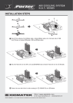
11
DISASSEMBLY PROCEDURE
PFFY-P20VKM-E
PFFY-P20VKM-ER1
PFFY-P32VKM-E
PFFY-P32VKM-ER1
PFFY-P25VKM-E
PFFY-P25VKM-ER1
PFFY-P40VKM-E
PFFY-P40VKM-ER1
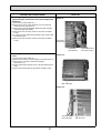
PHOTOS
OPERATING PROCEDURE
1. Removing the panel
Photo 1
(1) Push both sides of the upper part of the front grille and
pull the front grille open, and then remove the front grille
from the panel. (See Photo 1.)
(2) Remove the screws of the panel. (See Photo 2.)
(3) Open the horizontal vane and push the left, right and
middle of the upper part of the panel, and pull the panel
toward you. (See Photo 2.)
(4) Lift up the panel and remove it from the box.
Push
Push
Grille
Photo 2
Horizontal
vane
Push
23
Screws of the panel
Push
Push
OPERATING PROCEDURE
PHOTOS
Photo 3
2. Removing the indoor controller board and
address board
(1) Remove the panel. (Refer to 1.)
(2) Remove the screw of the electrical cover, and then the
electrical cover. (See Photo 3.)
(3) Remove the screw of the ground wires connected to the
indoor fan motor (lower), and then the ground wires. (See
Photo 4.)
(4) Remove the screw of the ground wires connected to the
indoor heat exchanger, and then the ground wires. (See
Photo 4.)
(5) Disconnect all the connectors on the address board and
remove the screw of the address board case.
(6) Remove the screw of the ground wire connected to the
indoor controller board, and then the ground wire.
(See Photo 4.)
(7) Pull the indoor controller board case slightly toward you
from the electrical box, and disconnect all the connectors
on the indoor controller board.
(8) Pull out the indoor controller board case from the electrical
box.
Water cover Screw of the
electrical cover
Hair pin cover
Photo 4
Address
board (A.B)
Screw of the
ground wire (I.B)
3. Removing the electrical box
(1) Remove the panel. (Refer to 1.)
(2) Remove the electrical cover. (Refer to 2.)
(3) Remove the ground wires from the electrical box.
(Refer to 2.)
(4) Remove the ground wires connected to the indoor fan
motor and ones connected to the indoor heat exchanger.
(See Photo 4.)
(5) Remove the screw of the electrical box. (See Photo 4.)
(6) Disconnect the following connectors on the indoor
controller board.
• Fan motor connectors <CNMF1, 2>
• Vane motor connector <CN6V1>
• Damper motor connector <CN6V2>
• Pipe temperature thermistor connector <CN44>
• Damper limit switch connector <CN36>
(7) Unhook the electrical box from the upper catch and pull out
the electrical box from the box.
Indoor
controller
board (I.B)
Terminal block
(TB2)
Screw of the
ground wire
(Heat exchanger)
Terminal block(TB5)
24
Screw of the
ground wire
(Fan motor)
OPERATING PROCEDURE
PHOTOS
Photo 5
4. Removing the vane motor (MV1)
(1) Remove the panel. (Refer to 1.)
(2) Remove the screws of the vane motor and pull out the
vane motor. (See Photo 5.)
(3) Disconnect the connector from the vane motor.
Screw of vane motor
5. Removing the indoor fan motor (upper)
(1) Remove the panel. (Refer to 1.)
(2) Remove the electrical box. (Refer to 3.)
(3) Remove the nozzle (upper). (See Photo 6.)
(4) Unhook the water cover from the catches and remove the
water cover. (See Photo 6.)
(5) Removing the screw of the motor band, and then the motor
band. (See Photo 7.)
(6) Remove the line flow fan and the indoor fan motor (upper)
from the box.
Photo 6
Nozzle <Upper>
Water cover
Photo 7
25
Screw of motor band
OPERATING PROCEDURE
PHOTOS
6. Removing the damper motor and the damper
limit switch
Photo 8
(1) Remove the panel. (Refer to 1.)
(2) Remove the screws of the nozzle assembly (lower).
(See Photo 8.)
(3) Remove the drain hose from the nozzle assembly (lower)
and pull out the nozzle assembly (lower) toward you.
(4) Remove the tape fixing the lead wires of the damper motor
from the nozzle assembly <lower>. (See Photo 9.)
(5) Remove the screws of the damper motor support, and
then the damper motor support.
(6) Remove the screws of the damper motor, and then the
damper motor from the damper motor support.
(7) Disconnect the connector from the damper motor.
(8) Remove the damper limit switch. (LS).
Screw of
the nozzle
Screw of
the nozzle
Drain
hose
Photo 9
7. Removing the indoor fan motor
(1) Remove the panel. (Refer to 1.)
(2) Remove the nozzle assembly (lower) and the drain hose.
(Refer to 6.)
(3) Remove the screw of the ground wire of the indoor fan
motor (lower), and then the ground wire. (See Photo 11.)
(4) Remove the screw of the motor band, and then the motor
band. (See Photo11.)
(5) Remove the line flow fan and the indoor fan motor (lower)
from the box.
Lead wires of the damper motor
Photo 10
Screw of the damper
motor support
Screw of the
damper motor
Photo 11
Screw of
the motor band
26
Screw of the
ground wire
OPERATING PROCEDURE
PHOTOS
8. Removing the pipe temperature detection
(liquid and gas) thermistors and room temperature
thermistor
(1) Remove the panel. (Refer to 1.)
(2) Remove the screw of the electrical cover, and then the
electrical cover. (See photo 3)
(3) Remove the pipe temperature detection (liquid and gas)
thermistors from the holders.
(4) Disconnect the connector CN44 on the indoor controller
board.
(5) Loosen the room temperature thermistor wire clamp under
the electrical box.
(6) Disconnect the connector CN20 on the indoor controller
board.
Photo 12
Thermistor
(Gas/TH23)
Thermistor
(Liquid/TH22)
9. Removing the heat exchanger and linear expansion
valve
Room temperature
thermistor (TH21)
Photo 13
(1) Remove the panel. (Refer to 1.)
(2) Remove the hair pin cover and water cover (See Photo 3.)
(3) Remove the 2 screws of the heat exchanger.
(See Photo 14.)
(4) Unhook the heat exchanger from 2 catches (electrical box
side).
(5) Pull out the heat exchanger and linear expansion valve.
Heat exchanger
Photo 14
Screws of the
heat exchanger
27
Hair pin cover
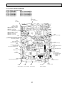
12
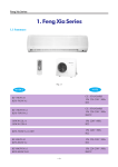
RoHS PARTS LIST
12-1. INDOOR UNIT ELECTRICAL PARTS AND FUNCTIONAL PARTS
PFFY-P20VKM-E
PFFY-P25VKM-E
PFFY-P32VKM-E
PFFY-P40VKM-E
PFFY-P20VKM-ER1
PFFY-P25VKM-ER1
PFFY-P32VKM-ER1
PFFY-P40VKM-ER1
23
22
21
1
2
3
4
15
24
5
17
6
16 15
7
20
8
16
9
14
13
10
18
4
11
19
12
28
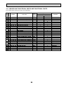
12-1. INDOOR UNIT ELECTRICAL PARTS AND FUNCTIONAL PARTS
No.
1
2
3
4
5
6
7
8
9
10
11
12
13
14
15
16
17
18
19
20
21
22
23
24
25
26
RoHS
Part number that is circled is not shown in the illustration.
G
G
G
G
G
G
G
G
G
G
G
G
G
G
G
G
G
G
G
G
G
G
G
G
G
G
G
G
G
Part No.
T7W E00
T7W E07
T7W E06
T7W E01
T7W E00
T7W E01
T7W E08
T7W E09
T7W E00
T7W E00
T7W E03
R01 E09
T7W E08
T7W E04
T7W E26
T7W E00
T7W E08
T7W E25
R01 E27
R01 H18
R01 H08
T7W E37
T7W E55
T7W E80
T7W E01
T7W E07
T7W E03
R01 E06
T7W E04
530
002
002
103
103
530
223
130
170
272
527
527
002
114
762
105
130
762
246
202
202
716
310
310
294
223
114
239
304
Symbol
in Wiring
Diagram
Part name
NOZZLE ASSEMBLY (UPPER)
HORIZONTAL VANE (UPPER)
HORIZONTAL VANE (LOWER)
VANE SLEEVE
BEARING ASSEMBLY
NOZZLE ASSEMBLY (LOWER)
MV2
DAMPER MOTOR
VANE MOTOR SUPPORT
SM SHAFT
LS
DAMPER LIMIT SWITCH (CLOSE)
DRAIN HOSE
DRAIN HOSE
VANE UNDER
LINE FLOW FAN (LOWER)
MF2
INDOOR FAN MOTOR (LOWER)
RUBBER MOUNT (L,R)
MOTOR BAND
MF1
INDOOR FAN MOTOR (UPPER)
TB5
TERMINAL BLOCK
ROOM TEMPERATURE THERMISTOR TH21
ROOM TEMPERATURE THERMISTOR TH21
TB2
TERMINAL BLOCK
I.B
INDOOR CONTROLLER BOARD
I.B
INDOOR CONTROLLER BOARD
A.B
ADDRESS BOARD
MV1
VANE MOTOR (SET)
LINE FLOW FAN (UPPER)
FUSE
FUSE
ADDRESS CABLE
29
Q'ty/unit
Remarks
PFFY-P20/25/32/40
VKM-E
1
1
1
3
2
1
1
1
1
1
1
1
1
1
2
2
1
1
1
1
1
1
1
1
1
1
VKM-ER1
1
1
1
3
2
1
1
1
1
1
1
1
1
1
2
2
1
1
1
1
1
1
1
1
1
1
UP & DOWN
ARW40Y8P30MS
ARW40Z8P30MS
3P (M1, M2, S)
3P (L, N, )
UP&DOWN
6.3A
12-2. STRUCTURAL PARTS
PFFY-P20VKM-E
PFFY-P20VKM-ER1
PFFY-P25VKM-E
PFFY-P25VKM-ER1
PFFY-P32VKM-E
PFFY-P32VKM-ER1
PFFY-P40VKM-E
PFFY-P40VKM-ER1
5
1
2
4
3
No.
RoHS
12-2. STRUCTURAL PARTS
1
2
3
4
5
G
G
G
G
G
Part No.
T7W
T7W
T7W
T7W
T7W
E01
E06
E05
E01
E01
635
651
691
500
808
Part name
Symbol
in Wiring
Diagram
BOX
PANEL ASSEMBLY
FRONT PANEL
CATECHIN AIR FILTER
BACK PLATE
30
Q'ty/unit
PFFY-P20/25/32/40VKM-E
PFFY-P20/25/32/40VKM-ER1
1
1
1
1
1
Remarks
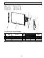
12-3. INDOOR UNIT HEAT EXCHANGER
PFFY-P20VKM-E
PFFY-P20VKM-ER1
PFFY-P25VKM-E
PFFY-P25VKM-ER1
PFFY-P32VKM-E
PFFY-P32VKM-ER1
PFFY-P40VKM-E
PFFY-P40VKM-ER1
5
4
3
2
1
No.
1
2
3
4
5
RoHS
12-3. INDOOR UNIT HEAT EXCHANGER
G
G
G
G
G
G
Part No.
T7W E00
T7W H56
T7W E01
T7W E16
T7W E19
R01 H23
031
480
031
202
401
401
Symbol
in Wiring
Diagram
Part name
HAIR PIN COVER
INDOOR HEAT EXCHANGER
WATER COVER
PIPE TEMPERATURE THERMISTOR TH22,TH23
LEV
EXPANSION VALVE
LEV
EXPANSION VALVE
31
Q'ty/unit
PFFY-P20/25/32/40
VKM-E
1
1
1
1
1
VKM-ER1
1
1
1
1
1
Remarks
TM
HEAD OFFICE : TOKYO BLDG., 2-7-3, MARUNOUCHI, CHIYODA-KU, TOKYO 100-8310, JAPAN
C Copyright 2006 MITSUBISHI ELECTRIC ENGINEERING CO.,LTD
Distributed in Nov. 2008 No. OC404 REVISED EDITION-A PDF 7
Distributed in Jul. 2006 No. OC404 PDF 8
Made in Japan
New publication, effective Nov. 2008
Specifications subject to change without notice.