1
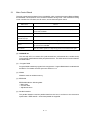
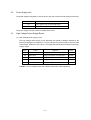
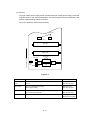
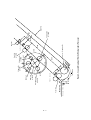
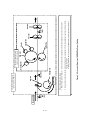
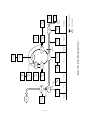
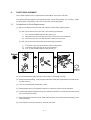
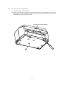
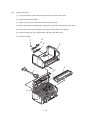
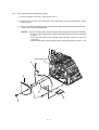
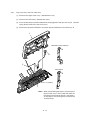
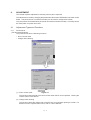
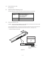
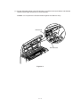
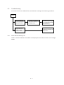
Thank You for purchasing this Factory Service Manual on EBAY from PCTECHINFO! Click Here for more Factory Service Manuals for other Computer and Printer / Copier Manufacturers from PCTECHINFO! OKIPAGE 6 LED Page Printer Maintenance Manual ODA All specifications are subject to change without notice. PREFACE This Maintenance Manual describes the field maintenance methods for LED Page Printers. This manual is written for use by service persons. Please note that you should refer to the Printer Handbook for the handling and operating methods of the equipment. CONTENTS 1. CONFIGURATION ..................................................................................... 1.1 System Configuration ........................................................................ 1.2 Printer Configuration .......................................................................... 1.4 Specification ...................................................................................... 1.5 Safety Standards ............................................................................... 1-1 1-1 1-2 1-3 1-5 2. OPERATION DESCRIPTION .................................................................... 2.1 Main Control Board ............................................................................ 2.2 Power Supply Unit ............................................................................. 2.3 High-Voltage Power Supply Board .................................................... 2.4 Electro-Photographic Processor ........................................................ 2.5 Electro-Photographic Process ........................................................... 2-1 2-3 2-4 2-4 2-6 2 - 10 2.5.1 2.6 2.7 2.8 2.9 Explanation of Each Process Operation .................................................. 2 - 12 Paper Jam Detection ......................................................................... Toner Low Detection.......................................................................... Cover Open ....................................................................................... Detecting I/D Unit existence .............................................................. 3. PARTS REPLACEMENT ........................................................................... 3.1 Precautions for Parts Replacement ................................................... 3.2 Parts Layout....................................................................................... 3.3 Replacing Parts ................................................................................. 3.3.1 3.3.2 3.3.3 3.3.4 3.3.5 3.3.6 3.3.7 3.3.8 3.3.9 3.3.10 3.3.11 3.3.12 3.3.13 3.3.14 3.3.15 3.3.16 3.3.17 3.3.18 2 - 18 2 - 18 2 - 21 2 - 21 3-1 3-1 3-3 3-6 Hopper Plate ........................................................................................... 3 - 6 LED Head and Head Spring .................................................................... 3 - 7 Transfer Roller ......................................................................................... 3 - 8 How to remove Cover Upper Assy .......................................................... 3 - 9 Upper Cover Assy ................................................................................... 3 - 10 High-Voltage Power Supply Board (P2H) ............................................... 3 - 11 Top Cover Assy and Flat Cable Assy ...................................................... 3 - 12 Paper Holder ........................................................................................... 3 - 13 Side Plate M and Idle Gear ..................................................................... 3 - 14 Heat Assy ................................................................................................ 3 - 15 Drive Shaft E (Eject) and Eject Roller ..................................................... 3 - 16 Pressure Roller B (Back Up Roller) ......................................................... 3 - 17 Separator Guide ...................................................................................... 3 - 18 Pulse Motor (Main) .................................................................................. 3 - 20 Hopping Shaft Assy ................................................................................. 3 - 21 Regist Roller ............................................................................................ 3 - 22 Paper Sensor E, Paper Sensor Exit and Toner Sensor Assy ................. 3 - 23 Base Plate ............................................................................................... 3 - 24 4. ADJUSTMENT ............................................................................….. 4.1 Adjustment Types and Functions ..........................…….....…..... 4-1 4-1 4.1.1 Printer Driver ………………………………………………………………… 4-1 4-2 4.1.2 Engine Maintenance Utility ……………………………….……… 4.2 Adjustment When Replacing a Part ……………………………… 4.2.1 Setting LED Head Drive Time ………………………………………… 4.2.2 Uploading and Downloading EEPROM Data ……………… 5. PERIODICAL MAINTENANCE ……………………………………… 5.1 Periodical Replacement Parts .................................................. 5.2 Cleaning .................................................................................... 5.2.1 Cleaning the LED Lens Array .................................................….. 6. TROUBLESHOOTING PROCEDURES ......................................… 6.1 Troubleshooting Tips ...........................................................… 6.2 Check Points Before Correcting Image Problems ................… 6.3 Notes When Correcting Image Problems ..............................… 6.4 Preparation Before Troubleshooting ......................................… 6.5 Troubleshooting .....................................................................… 4-2 4-2 4-3 5-1 5-1 5-2 5-2 6-1 6-1 6-1 6-1 6-1 6-2 6.5.1 Status Monitor Message List ...................................…………….……… 6-3 6.5.2 Status Message Troubleshooting ................................…….….. 6.5.3 Image Troubleshooting ................................................…….….. 6-6 6 - 12 7. WIRING DIAGRAM ......................................................................... 7.1 (b)Interconnect Signal Diagram (OKIPAGE 6w) ...................… 7.2 PCB Layout ...........................................................................… 7-1 7 -1 7 -2 7.2.1 a) Main Control Board (HBY PCB) (OKIPAGE 6w EPROM type) .…… 7 -2 7.2.2 High-Voltage Power Supply Board ........................................... 7 -3 8. PARTS LIST .................................................................................... 8 -1 APPENDIX A LOCAL PRINTING/ DEMO PAGE PRINTING ............. APPENDIX B PARALLEL INTERFACE ............................................. APPENDIX C MAINTENANCE UTILITY GUI MANUAL (OKIPAGE 6W) A-1 B-1 C-1 1. CONFIGURATION 1. CONFIGURATION 1.1 System Configuration The OKIPAGE 6w consists of a control block, a power supply unit, and an engine block. (See Figure 1-1.) ENGINE UNIT Paper Feed Mechanism Hopper Plate Electro-photographic Processor Main High-Voltage Power Supply Board Sub High-Voltage PowerSupply Board Main Control Board Power Supply Unit Figure 1-1 1-1 1.2 Printer Configuration The printer unit consists of the following five hardware components: • • • • • Electro-Photographic Processor Paper Feeder Main Control Board High-Voltage Power Supply Board (two Boards) Power Supply Unit Figure 1-2 is the configuration of the printer unit. Upper Cover Assy I/D Unit (Type 6) Top Cover Assy Heat Assy Main Control Board High-voltage Power Supply Board (P6L) High-voltage Power Supply Board (P2H) 1-2 1.4 Specification (1) Type Desktop (2) Outside dimensions (excludes protruding portion) Height 6.7” Width 12.8” Depth 8.1” (3) Weight 4.2 kg (with Image Drum Cartridge and Toner Cartridge) (4) Development method Exposure method Dry non-magnetic development system LED stationary head (5) Paper used <Type> • Standard paper – Xerox 4200 (20 lbs) • Application paper (manual face-up feed) – Label – Envelope – OHP paper (Transparency) (170 mm) (324 mm) (207 mm) <Size> 14" (355.6 mm) x 8.5" (215.9 mm) (Max.) 5" (127mm) x 3" (76.2mm) (Min.) <Thickness> – Automatic feed: – Manual feed: (6) Printing speed First print: Continuous print: Warm-up time: 16 to 28 lbs (60 to 105 g/m2) Label, Envelope, OHP paper (transparency), 16 to 32 lbs (60 to 120g/m2) 13 seconds (A4) (after warm-up) 6.11 sheets/minute (Letter) 5.87 sheets/minute (A4) 34 seconds (230 VAC for OEL/INT) (at room temperature 77 ßF (25 ßC)) (7) Paper feeding method Automatic paper feed or manual paper feed (8) Paper delivery method Face up (9) Resolution 300 dpi x 300 dpi, Quasi 600 dpi (10) Power input 230 VAC ±10% (for OEL/INT) (11) Power consumption Peak: Typical operation: Idle: Power save mode: 1-3 Approx. 450W Approx. 150W Approx. 30W Approx. 5W (12) Temperature and humidity Temperature Humidity During operation 10 to 32 ˚C 20 to 80% RH (relative humidity) In storage –10 to +43 ˚C 10 to 90% RH (relative humidity) No condensation is permissible. Caution: Temperature and humidity in storage are measured with the OKIPAGE 8p/8w being packed; they are valid for one year. (13) Noise (conformity with ANSI) During operation: Avg. 50 dB (A), slow (without peak sounds) Standby: Background level (14) Consumables Toner cartridge kit 1,500 (5% duty) ........ 45g cartridge kit Image drum cartridge 10,000 (at continuous printing) 1-4 1.5 Safety Standards 1.5.1 Certification Label The safety certification label is affixed to the underside of the OKIPAGE 6w 1.5.2 Warning Label Warning labels are affixed to the locations that may cause bodily injury. During maintenance, do work with enough care while following instructions on these warning labels. For OEL, OKI-INT For ODA, OEL, OKI-INT For Korea 1-5 For China, TAIWAN 2. OPERATION DESCRIPTION 2. OPERATION DESCRIPTION The OKIPAGE 6w consists of a main control board, two high-voltage power supply boards, a power supply unit, and an electro-photographic processor. The OKIPAGE 6w receives print data from a higher-level interface and sequentially stores it in memory. The OKIPAGE 6w decodes and edits the received data while storing print data from the interface in memory. It sequentially transfers the edited data to the LED head for each dot line. The electro-photographic processor then prints the data on sheets of paper. The display of the higher-level host is used for device operation and status display. Figure 2-1 is the block diagram of the OKIPAGE 6w. 2-1 2-2 Parallel I/F CN4 CN8 PLUNGER 0V Serial I/F EEPROM 1kb OSC 16MHz CN1 ID Unit High Voltage Power Unit P2H RST HC125 High Voltage Power Unit P6L CN10 DRAM 512kB DRAM 1M x 4 Figure 2-1-2 Block Diagram (OKIPAGE 6w) Power Supply Unit CN2 CPU (nX8) Motor Driver MTD2005F CN7 PCB H63-ONLY DRAM Bus Internal (Data : 4) MASK ROM (Address : 11) 62KB +26V +5V 0V 0VP LS07 5V HEAD1 LED HEAD Motor 2.1 Main Control Board The main control board consists of a one-chip MCPU, which contains the program ROM, a DRAM, an EEPROM, a host interface circuit, and a mechanism driving circuit. The mechanism driving circuit consists of a LED head, a main motor, and an electromagnetic clutch. Built-in Device Function DRAM controller Controls DRAM. DMA controller Transfers image data from Parallel I/F to DRAM, from DRAM to a video output port and between CPU and DRAM. Parallel interface controller Controls the parallel interface. Video output port LED STB output port Controls LED head. Timer Generates various control timings for monitoring paper feeding and a paper size. I/O port Inputs and outputs the sensor signals and motor signals, etc. Also performs I/O for EEPROM. A/D converter Inputs the feedback signals from a high-voltage generation circuit and thermistor signal. (1) OKIPAGE 6w The one-chip CPU is a custom CPU (8-bit internal bus, 8-bit external bus, 16-MHz clock) incorporating mask ROM and CPU peripheral devices. This CPU has the functions listed in the table below. (2) • Program ROM Program ROM contains a program for the equipment. Program ROM data is contained with the MCPU. For details of PCB Layout see Section 7.2.2. (3) DRAM DRAM is used as resident memory. (4) EEPROM EEPROM holds the following data: • Menu data • Counter value • Adjustment value (5) Parallel interface The parallel interface receives parallel data from the host; it conforms to the Centronics specification. IEEE-1284 B: – directional parallel is supported. 2-3 2.2 Power Supply Unit The power supply unit supplies +5 V and +26 V to the main control board according to 230 VAC / Output voltage Application +5 V Used to generate a logic circuit and a high voltage. +26V Used to drive the motor and electromagnetic clutch. The power supply unit also contains a heater drive circuit. 2.3 High-Voltage Power Supply Board (1) High-Voltage power supply circuit The high-voltage power supply circuit generates the following voltages required for the electro-photographic processor from +5 V according to the control sequence from the main control board. When the cover is open, +5 V supply is automatically interrupted to stop highvoltage output. Output Voltage Application Remarks CH –1.3 KV Voltage to be applied to a charge roller. P2H-PCB DB –265 V/+265 V Voltage to be applied to a developing roller. P2H-PCB SB –550 V/ 0 V Voltage to be applied to a sponge roller. P2H-PCB CB +400 V/–1.35 KV Voltage to be applied to a cleaning roller. P6L-PCB TR +500 V ~ +3.5 KV/–750 V Voltage to be applied to a transfer roller. P2H-PCB Caution: The TR voltage varies with medium and transfer roller impedance. 2-4 (2) Sensors The high-voltage power supply board consists of the high-voltage power supply circuit that supplies power to the electro-photographic processor system and the photosensor that detects a paper feeding system and toners. Figure 2-2 shows the sensor layout drawing. Exit roller Outlet sensor Heat roller Transfer roller Feed roller Paper feeding direction Paper sensor Toner sensor assy Hopping roller Manual feed sensor Figure 2-2 Sensor Function Sensing State Manual feed sensor Monitors whether paper was inserted into the manual feed sensor section. ON: Paper exists. OFF: No paper exists. Paper sensor Detects the leading part of the paper. Monitors paper feeding. ON: Paper exists. OFF: No paper exists. Outlet sensor Monitors paper feeding and the paper size according to the paper sensor arrival and passing time. ON: Paper exists. OFF: No paper exists. Toner sensor Detects the low toner status. ON (long): Toner low OFF (short): Toner High 2-5 2.4 Electro-Photographic Processor The electro-photographic processor prints out the image data to be sent from the main control board on sheets of paper. Figure 2-3 shows the layout drawing of the electro-photographic processor. (1) Image drum unit The image drum unit makes a toner adhere to the formed electrostatic latent image with static electricity. This electrostatic latent image is formed by the lights irradiated from LED heads. (2) Electromagnetic clutch The electromagnetic clutch controls the rotation of the hopping roller according to signals from the control block. 2-6 2-7 ON OFF 10 Manual feed sensor Manual printing Feed roller 23.18 10 17.23 OFF 12.72 32.00 6.85 Cleaning roller (ø 9.000) 64.60 Hopping roller 20.32 26.50 Outlet sensor OFF Transfer roller (ø 15.000) ON 10 Figure 2-3 Layout Drawing of Electro-Photographic Processor Tray printing Paper sensor Developing roller (ø 14.000) Drum roller (ø 16.000) LED head 6.77 Charge roller (ø 9.000) Heat roller (ø 19.910) Exit roller Single tray (3) Pulse motor (Main) This pulse motor of 48 steps/rotation is two-phase excited by the signal from the main control board; it performs feeding control by switching normal rotation to reverse rotation or vice versa and turning on/off the electromagnetic clutch. The relationship between the main motor, electromagnetic clutch, resist gear, drum gear, hopping roller is shown in the table below and on the subsequent pages. Main Motor Electromagnetic Clutch Hopping Roller Regist Gear Drum Gear Operation Normal rotation OFF Non-rotation Non-rotation Rotation Warm-up ON Rotation Rotation Rotation Hopping OFF Non-rotation Rotation Rotation Prinitng Reverse rotation (4) LED head The shift and latch registers receive image data from the main control board for each dot line. 2,496 LEDs are driven to radiate the image drum. (5) Heat Assy The heat Assy consists of a heater, a heat roller, a thermistor, and a thermostat. The power supply unit supplies AC voltage to the heater according to the HEATON signal from the main control board to heat the heat roller. The main control board monitors the heat roller temperature via the thermistor and keeps the temperature constant by turning on/off the heater AC voltage supply. If the heat roller temperature rises abnormally, the thermostat of the heater voltage supply circuit functions to forcibly suspend the AC voltage supply. 2-8 2-9 Manual feed sensor Manual printing Heat roller Outlet sensor Exit roller Drum roller, transfer roller, cleaning roller, CH roller, developing roller, heat roller, exit roller, feed roller, hopping roller rotation Hopping operation from the tray, however, is performed when the electromagnetic clutch is turned on. Drum roller, transfer roller, cleaning roller, CH roller, developing roller, heat roller, exit roller rotation Transfer roller Cleaning roller CH roller Figure 2-4 Schematic Drawing of OKIPAGE6w Paper Feeding 2 Reverse rotation of pulse motor (main): Roller control by pulse motor (main) 1 Normal rotation of pulse motor (main): TRAY printing Drum roller 1 Motor to be driven by normal rotation of pulse motor (main) Developing roller Hopping roller Paper sensor Feed roller 2 Roller to be driven by reverse rotation of pulse motor (Main) 2.5 Electro-Photographic Process (1) Electro-photographic process The electro-photographic process is outlined below. 1 Charging The surface of the OPC drum is charged negatively and uniformly by applying the DC voltage to the CH roller. 2 Exposure Light emitted from the LED head irradiates the negatively charged surface of the OPC drum. The surface potential of the irradiated surface attenuates to form the electrostatic latent image corresponding to the image signal. 3 Development and residual toner recovery The negatively charged toner is brought into contact with the OPC drum, adhering to the electrostatic latent image on the OPC drum by static electricity. This adhesion causes the electrostatic latent image to change to a visible image. At the same time, the residual toner on the OPC drum is attracted to the developing rollerby static electricity. 4 Transfer When paper is placed over the image drum surface, the positive charge which is opposite in polarity to that of the toner, is applied to the reverse side by the transfer roller. The toner is attracted by the positive charge and is transferred onto the paper. This results in the transfer of the toner image formed on the image drum onto the paper. 5 Cleaning The cleaning roller temporarily attracts the residual toner on the transferred OPC drum with static electricity, then returns the toner to the OPC drum. 6 Fusing The transferred unfused toner image is fused to a sheet of paper by applying heat and pressure to the image. Figure 2-5 is a flow for the electro-photographic process. 2 - 10 2 - 11 Paper ejection Fusing Fusing Paper feeding Heat roller Outlet sensor Paper eject roller Paper delivery Back-up roller Power supply Transfer Cleaning Charging Transfer roller Transfer Exposure LED head Development Paper sensor Development Developing roller Power supply Paper feed Feed roller Figure 2-5 Flow for Electro-Photographic Process Cleaning Cleaning roller Power supply Charge roller Power supply Control signal Paper hopping Manual feed sensor Manual feed section Paper holder : Paper feeding path : OPC drum rotation direction Hopping roller Paper supply Toner cartridge 2.5.1 Explanation of Each Process Operation (1) Hopping As shown in the figure below, the clutch for hopping is turned on/off according to current ON/ OFF to a coil. When the clutch is OFF Spring for resetting Clutch plate Hopping gear Coil Magnetic substance plate Pin Hopping shaft Hopping roller Engagement section When the clutch is ON Clutch plate Hopping gear When the clutch is on, the hopping gear engages with the clutch plate to rotate the hopping roller. When the clutch is off, the hopping gear is separated from the clutch plate by the spring for resetting, disabling the rotation of the hopping roller. 2 - 12 (2) Printing and warm-up At warm-up Triple gear Transfer gear Regist gear Idle gear Planetary gear a" a' a Hopping gear Gear A Pulse motor (main) Rotate the pulse motor (main) in the a direction. The planetary gear rotates in the a’ direction, dislocating its position in the a” direction. This causes the planetary gear to be separated from gear A. The hopping gear will not rotate. The triple gear and transfer gear rotate via the idle gear to drive the EP unit. At printing Triple gear Transfer gear Regist gear Idle gear Planetary gear b" b' b Hopping gear Gear A Pulse motor (main) The paper is further advanced in synchronization to the print data. 2 - 13 (3) Charging Charging is performed by applying DC voltage to the charge roller that is in contact with the surface of the OPC drum. Highvoltage power supply Charge roller OPC drum (4) Exposure Light emitted from the LED head irradiates the negatively charged surface of the OPC drum. The surface potential of the irradiated surface attenuates to form the electrostatic latent image corresponding to the image signal. LED head Highvoltage power supply LED head Charge roller Paper OPC drum 2 - 14 Image drum (5) Development The electrostatic latent image on the surface of the OPC drum is changed to a visible toner image by applying a toner to it. Development is performed in the contact part between the OPC drum and developing roller. 1 The sponge roller negatively charges a toner and applies it to the developing roller. Developing blade Charge roller Developing roller Sponge roller OPC drum 2 The toner applied to the developing roller is thin-coated by the developing blade. 3 A toner adheres to the exposure part of the OPC drum in the contact part between the OPC drum and developing roller. This causes the electrostatic latent image to be changed to a visible image. 2 - 15 (6) Transfer The transfer roller is composed of conductive sponge material. This roller is set so that the surface of the OPC drum and sheets of paper will adhere closely. A sheet of paper is placed on the surface of the OPC drum and the positive charge opposite to the negative charge of a toner is applied from the reverse side by the transfer roller. When a high negative voltage is applied from the power supply to the transfer roller, the positive charge induced on the surface of the transfer roller moves to the paper side at the contact part between the transfer roller and the sheet of paper. The positive charge on the lower side of the sheet of paper then causes the negatively charged toner adhering to the surface of the OPC drum to move to the upper side of the sheet. This enables transfer to the sheet of paper. OPC drum Paper High-voltage power supply Transfer roller 2 - 16 (7) Fusing The transferred unfused toner image is fused to a sheet of paper because heat and pressure are applied when it passes between the heat roller and back-up roller. The Teflon-coated heat roller contains a 400 W heater (Halogen lamp) that heats the heat roller. The thermistor on the surface of the heat roller keeps the temperature of the heat roller constant. A thermostat is also installed for safety. If temperature rises abnormally, this thermostat opens to suspend voltage supply to the heater. The back-up roller is pressurized to the heat roller by the pressure spring on each side. Thermistor Separation claw Heater roller Heater Back-up roller Pressure Spring (8) Cleaning After transfer has terminated, the cleaning roller temporarily draws in the untransferred residual toner adhering to the OPC drum with static electricity and then returns it to the OPC drum. OPC drum Cleaning roller High-voltage power supply Transfer roller 2 - 17 2.6 Paper Jam Detection The OKIPAGE 6w monitors the paper status when the power supply is on and during printing. In the following cases, the OKIPAGE 6w interrupts the printing process as a paper jam. Printing can be recovered by opening the cover, removing the jammed paper, and closing the cover. Paper Feed Check List Error Paper inlet jam Cause of Error • Only the manual feed sensor detects "Paper exists" when the power supply is on. • The leading part of the paper does not reach the paper sensor although hopping operation was performed three time. Paper feed jam • The leading part of the paper does not reach the outlet sensor within a fixed time after it has passed the paper sensor. Paper outlet jam • The trailing part of the paper does not pass the outlet sensor within L mm after the leading part of the paper has passed the outlet sensor. 2.52" (64 mm) <= L <= 15.77" (400.6 mm) Paper size error • The trailing part of the paper does not pass the paper sensor within L mm after the leading part of the paper has passed the paper sensor. 2.52" (64 mm) <= L <= 15.77" (400.6 mm) 2.7 Toner Low Detection Error Type of Error Reference Value Supervisory Sensor Pluse Minus Paper feed error Electromagnetic clutch ON/ Paper sensor ON 69.8 35 — Paper feed jam1 Paper sensor ON/ Outlet sensor ON 122.9 20.0 — Paper size error Paper sensor ON/ Paper sensor OFF 2.52" (64 mm) <= L <= 15.77" (400.56 mm) — — Paper outlet jam Outlet sensor ON/ Outlet sensor OFF 2.52" (64 mm) <= L <= 15.77" (400.56 mm) 45.0 45.0 Paper feed jam 2 Paper end sensor OFF/ Outlet sensor OFF 121.9 20.0 20.0 Unit: mm 2 - 18 Pulse motor (main) Normal rotation OFF Reverse rotation Electromagnetic clutch OFF ON Manual feed sensor OFF ON OFF ON Paper sensor Outlet sensor OFF ON Warm-up Paper feed Printing Operation mode Timing Chart for Paper Feed (Tray Feed) 2 - 19 • Hardware configuration of toner sensor The figure below shows the hardware configuration of the toner sensor. • Toner detection method Image drum unit Agitation bar (iron) Magnet Toner sensor lever Hardware Configuration of Toner Sensor (1) Toner sensor monitoring conditions are shown in the figure below. Caution: The toner sensor is not monitored when the drum is inactive. Toner sensor Magnet draw-in t1 T (a) When the toner-low state continues twice, Toner Low occurs. (This state is monitored at a cycle of 40 milliseconds.) (b) When the toner-full state continues twice, Toner Low is released. (This state is monitored at a cycle of 40 milliseconds.) (c) When the toner sensor does not change over two cycles (T x 2), the toner sensor alarm state occurs. (d) After the EP unit has been replaced (after the drum counter has been reset), Toner Low is not detected when the drum counter indicates 1 to 100 counts. 2 - 20 (2) The basic rotation cycle of the toner sensor is as follows: T time Basic rotation cycle of toner sensor 2.5 sec. Toner low time t1 > 0.64 sec. 0.64 sec. > t1 > 0.28 sec. Toner full time 2.8 Cover Open Opening the stacker cover turns off the microswitch on the high-voltage power supply board to suspend +5 V supply to the high voltage power supply. This results in the stop of all high-voltage outputs. At the same time, the CVOPN signal is issued to notify the main control board of the switch status and cover open processing is executed. 2.9 Detecting I/D Unit existence In this model, a micro switch may be activated, applying a high voltage to the machine under a state where the cover is slightly opened. In this case, there is a fear that, when a user insert his hand through the opening, he may be shocked unless an I/D Unit has been installed. (Safety standard measures EN60950: 1992) Therefore, with mechanism, an interlock system for micro switch shall be added if a machine has no mechanism with I/D Unit inside. Also, for control, I/D Unit existence detection shall be implemented according to the following method. <Conditions for judging I/D Unit existence> If a toner sensor does not change for 1.2 cycle of toner sensor basic rotation cycle soon after powering on or closing cover, no installed I/D Unit shall be judged, stopping Warming Up motion to shift the machine mode to light malfunction. But this error can be recovered by cover open and close operation after installing I/D Unit. I/D Unit existence detection time T time Remarks 3.04 sec. As the toner sensor monitors at intervals of 40 msec. the fractional part should be rounded down. The conditions for enabling this error should be as follows: Valid condition Invalid condition In the case of 31 pages or more in total drum counter In the case of 30 pages or less in total drum counter, a significant malfunction toner sensor error shall occur. When the toner sensor breaks down with 31 or more counted in total at the drum, I/D Unit not Install will be displayed without fail at power on. Even in this case, the machine should be in printable state so that printing can be guaranteed until the completion of toner repair. (See the drawing in the next page). 2 - 21 Abnormal toner sensor waveform POWER ON Other cases I/D Unit not Installed displayed/informed Cover open/close Abnormal toner sensor waveform Status_A Status_B Normal Normal Cover open/close Abnormal toner sensor waveform Cover open/close Normal toner sensor waveform Normal printing Toner Sensor Error di splayed/informed ON LINE Abnormal toner sensor waveform Normal printing OKIPAGE 6w I/D Unit not Installed / Toner Sensor Error Draft for specification 1. Toner sensor error/I/D Unit not Installed state should not be stored in the EEPROM. 2. A shift to I/D Unit not Installed and Toner Sensor Error shall be made at cover open or close. 2 - 22 3. PARTS REPLACEMENT 3. PARTS REPLACEMENT This chapter explains how to replace parts, assemblies, and units in the field. The replacement procedures to be explained here include dismounting, not mounting. When mounting parts, assemblies, and units, reverse the dismounting steps. 3.1 Precautions for Parts Replacement (1) Be sure to dismount the AC cord and interface cable before replacing parts. (a) Be sure to dismount the AC cord in the following procedures: i) Turn off the POWER switch of the printer (“0“). ii) Disconnect the AC inlet plug of the AC cord from the AC receptacle. iii) Disconnect the AC cord and interface cable from the printer. (b) Be sure to reconnect the printer in the following procedures: i) Connect the AC cord and interface cable to the printer. ii) Connect the AC inlet plug to the AC receptacle. iii) Turn on the POWER switch of the printer (“|”). (2) Do not disassemble parts as long as the printer is operating normally. (3) Minimize disassembling. (Only the parts indicated in the parts replacement procedures can be dismounted.) (4) Use only the specified maintenance tools. (5) Disassemble parts in the specified sequence; otherwise, parts may be damaged. (6) Temporarily tighten small parts such as screws and collars to the original locations because they tend to be lost easily. (7) When handling ICs such as CPUs, RAM and PC boards, do not wear gloves that easily cause static electricity. (8) Do not place PC boards directly on devices and floors. 3-1 [Maintenance Tools] Table 3-1 lists the maintenance tools necessary for parts replacement. Table 3-1 Maintenance Tools No. Maintenance Tools Q'ty Use 1 No. 1-100 Philips screwdriver 1 2~2.5 mm screw 2 No. 2-100 Philips screwdriver 1 3~5 mm screw 3 No. 3-100 Philips screwdriver 1 4 No. 5-200 screwdriver 1 5 Digital multimeter (tester) 1 6 Pliers 1 7 Handy cleaner 1 Remarks [Maintenance Utility] Table 3-2 Maintenance Utility No. 1 Maintenance Utility Q'ty Maintenance utility 3-2 1 Use Remarks [Upper Cover Assy] (OKIPAGE 6w) Spur gear (A) Guide side (R) Hopper plate Upper cover Figure 3-1-2 3-3 Guide side (L) [Base Frame Unit] LED head Flat cable assy Head spring Top cover assy Pressure roller (B) (Back up roller) Paper guide (R) Heat assy Paper guide (L) Transfer roller Registration roller Side plate M Idle gear heat Drive shaft E (eject) Paper holder Hopper spring Tension plate Magnet H (hopping shaft) Stopper spring Hopping shaft assy Roller holder Hopping roller Toner cartridge unit (type 6) High-voltage power supply board P2H Pulse motor (Main) Sheet guide Power sensor E Figure 3-2 3-3 I/D unit (Type 6) [Base Plate Unit](OKIPAGE 6w Mask CPU type) Power supply unit Main control board High Voltage Power Supply board P6L Base plate assy Figure 3-3-1 3-5 3.3 Replacing Parts This section explains how to replace parts and assemblies. 3.3.1 Hopper Plate (1) Remove two claws and dismount hopper plate 1. 1 3-6 3.3.2 LED Head and Head Spring (1) Open top cover assy 1. (2) Dismount the left clamp and LED head 2. Then, dismount flat cable assy 3. (3) Dismount two head springs 4. 2 3 4 4 1 3-7 3.3.3 Transfer Roller (1) Open top cover assy 1 and dismount I/D unit (Type 6) 2. (2) Remove the washer TR 6 (make sure to do it) 1: Insert a flat-tip driver between the claw and the guide gear T 7 in a way of pushing gear T 5 so that it hits the left side and rotate the driver. 2: Pull off the post of the gear T 5 from the hole of the claw by lifting the shaft of transfer roller 3 with another driver while maintaining the avobe state in 1. Flat-tip driver 2 Guide gear T Claw 4 6 Transfer roller 5 7 Gear T 3 4 Label 1 3 -8 3.3.4 How to remove Cover Upper Assy (1) Unscrew screws on the rear part. (2) Open Cover Top Assy. Inserting a screwdriver head into a slot marked with Å¢ on the Plate Base edge, turn the screwdriver and lift Cover Upper Assy upward. Repeat the same procedure for another slot on the edge. Positions to insert screwdriver 3-9 3.3.5 Upper Cover Assy (1) Turn off the power switch and unplug the AC cord from the AC socket. (2) Disconnect interface cable 1. (3) Open top cover assy 2 and dismount I/D unit (Type 6) 3. (4) Move paper guide (L) 4 and paper guide (R) 5 on the rear of the printer to the center. (5) Remove two front claws of upper cover assy 6 and lift upper cover assy 6. (6) Dismount spur gear (A) 7, guide slide (L) 8, and guide slide (R) 9. (7) Dismount lens 0. 9 7 8 6 3 1 2 5 4 3 - 10 0 3.3.6 High-Voltage Power Supply Board (P2H) (1) Dismount upper cover assy. (See Section 3.3.5.) (2) Remove three screws 1 and remove the cover 2 and draw out high-voltage power supply board(P2H) 3. (3) Disconnect all the cables 4 from high-voltage power supply board(P2H) 3 and dismount highvoltage power supply board(P2H) 3. Caution: Note the following when assembling the high-voltage power supply board(P2H): • Mount the high-voltage power supply board(P2H) with top cover assy removed or open. • Take care that cable 4 will not interfere with the paper sensor exit when it is connected. • Replacement parts of High-Voltage Power Supply Board (P6L) is see 3.3 18) Paper sensor exit 4 2 3 4 1 1 3 - 11 3.3.7 Top Cover Assy and Flat Cable Assy (1) Dismount the upper cover assy. (See Section 3.3.5.) (2) Dismount the LED head. (See Section 3.3.2.) (3) Press the left clamp outward and dismount the engagement and top cover assy 1. (Tension spring 2 also comes off at the same time.) (4) Disconnect connector HEAD1on the control board and dismount flat cable assy 3. 1 OKIPAGE 6w Mask ROM type 3 3 2 OKIPAGE 6w 3 connector (HEAD1) Note: When reassembling these parts, make sure that the flat cable assy is firmly fitted with both the LED Head and connector Head 1 and Head 2. An improper fit may damage the control board and LED head. 3 - 12 3.3.8 Paper Holder (1) Dismount the upper cover assy. (See Section 3.3.5.) (2) Dismount paper holder 1. (3) Unlock and dismount paper guide (L) 2 and paper guide (R) 3. (4) Remove the claw and dismount hopper spring 4. (5) Remove the claw and dismount stopper spring 5. 3 4 5 2 1 3 - 13 3.3.9 Side Plate M and Idle Gear Perform parts replacement while making the base frame assy stand so that side plate M will face upward. (1) Dismount the upper cover assy. (See Section 3.3.5.) (2) Remove two screws 1 and two claws, then dismount plate side M2. (3) Dismount earth plate 3, two idle gears P 4, idle gear M5, idle gear 3R6, idle gear 2R7, idle gear heat 8, regist bearing 9 and bearing gear 0. 8 4 9 6 0 4 5 2 7 3 1 1 3 - 14 3.3.10 Heat Assy This section explains how to dismount the heat assy and parts in the assy. <Dismounting the heat assy> (1) Dismount the upper cover assy. (See Section 3.3.5.) (2) Dismount the high-voltage power supply board (P2H). (See Section 3.3.6.) (3) Remove two screws 1, disconnect connector 2, and dismount heat assy 3. 1 1 3 2 3 - 15 3.3.11 Drive Shaft E (Eject) and Eject Roller (1) Dismount the upper cover assy. (See Section 3.3.5.) (2) Dismount top cover assy. (See Section 3.3.7.) (3) Remove two screws 1 from heat assy (Section3.3.10), lift the heat assy, and dismount idle gear E (A) 2 and idle gear E (B) 3. (4) Unlock and dismount drive shaft E (Eject) 4. (5) Dismount two eject rollers 5. 4 3 5 1 1 3 - 16 2 3.3.12 Pressure Roller B (Back Up Roller) (1) Dismount the upper cover assy. (See Section 3.3.5.) (2) Dismount the high-voltage power supply board (P2H). (See Section 3.3.6.) (3) Dismount the heat assy. (See Section 3.3.10.) (4) Dismount the engagement with the left ground, then pressure roller B1. (Two bearing BUs 2 and two bias springs 3 also come off at the same time.) 2 1 4 2 3 3 - 17 3.3.13 Separator Guide (1) Dismount the upper cover assy. (See Section 3.3.5.) (2) Dismount the high-voltage power supply board (P2H). (See Section 3.3.6.) (3) Remove four screws 1. (4) Dismount inlet 2 from base frame 3. <Dismounting inlet 2> Insert a screwdriver into the hole on the side of base frame 3, remove the inlet claw from base frame 8, and dismount inlet 2. (5) Disconnect three cables 4 and connector A and dismount base frame 3. Then, remove screw 0. <Disconnecting connector A, B> Dismount connector A by drawing it upward while pushing the clamp lever with a standard screwdriver. (6) Dismount the paper holder assy. (See Section 3.3.8.) (7) Dismount two engagements and sheet guide 5. (8) Dismount friction pad 6, compression spring S7, and separator guide 8. (9) Dismount paper sensor E9. 3 - 18 <Dismount Inlet> 1 2 3 1 6 8 Screw driver <Disconnecting Connector> 4 4 9 1 A (-) Screw driver A Clamp lever <Disconnecting Connector> B B 1 CN2 OKIPAGE 6w (Mask CPU type) 3 - 19 3.3.14 Pulse Motor (Main) (1) Dismount the upper cover assy. (See Section 3.3.5.) (2) Dismount the high-voltage power supply board (P2H). (See Section 3.3.6.) (3) Dismount side plate M. (See Section 3.3.9.) (4) Dismount the base frame. (See Section 3.3.13.) (5) Remove two screws 1 and dismount pulse motor (main) 2. 1 2 3 - 20 3.3.15 Hopping Shaft Assy (1) Dismount the upper cover assy. (See Section 3.3.5.) (2) Dismount the high-voltage power supply board (P2H). (See Section 3.3.6.) (3) Dismount the base frame. (See Section 3.3.13.) (4) Dismount the paper holder assy. (See Section 3.3.8.) (5) Dismount the sheet guide. (See Section 3.3.13.) (6) Dismount side plate M. (See Section 3.3.9.) (7) Raise up roller holder 3, slide hopping shaft assy 1, and dismount roller holder 3 and hopping roller 4. (Knock pin 5 also comes off at the same time. Take care not to lose it.) (8) Draw out hopping shaft assy 1 to the right and dismount magnet H6. 2 5 1 6 3 4 3 - 21 3.3.16 Regist Roller (1) Dismount the upper cover assy. (See Section 3.3.5.) (2) Dismount Idle gear R 3 and Gear R 4. (3) Move regist roller 1 to the right and dismount it by lifting. (Two regist bearings 2 also come off at the same time. Take care not to lose them.) 1 3 2 2 4 3 - 22 3.3.17 Paper Sensor E, Paper Sensor Exit and Toner Sensor Assy (1) Dismount the upper cover assy. (See Section 3.3.5.) (2) Dismount the high-voltage power supply board (P2H). (See Section 3.3.6.) (3) Dismount the base frame. (See Section 3.3.13.) (4) Dismount the paper holder assy. (See Section 3.3.8.) (5) Dismount the sheet guide. (See Section 3.3.13.) (6) Dismount the heat assy. (See Section 3.3.10.) (7) Dismount drive shaft E. (See Section 3.3.11.) (8) Dismount paper sensor E1. (9) Dismount paper sensor exit 2. (10) Dismount toner sensor assy 3. 2 3 1 3 - 23 2 1 5 1 7 3 4 5 8 B 9 0 C A 9 A OKIPAGE 6w (Mask CPU type) 3 - 24 4. ADJUSTMENT 4. ADJUSTMENT This chapter explains adjustment necessary when a part is replaced. This adjustment is made by changing the parameters values set in EEPROM on the main control board. The printer driver or maintenance utility can be used to change these values. Only servicemen and maintenance personnel can use the maintenance utility. This utility cannot be made public for printer end users. 4.1 Adjustment Types and Functions 4.1.1 Printer Driver (For Microsoft Windows) This printer driver has the following functions: • Drum counter reset • Charge roller cleaning 6w (1) Drum counter reset Figure 4-1 This function resets the life of the drum counter when the EP unit is replaced. Clicking the “Reset” button resets the life. (2) Charge roller cleaning This function cleans the charge roller of the EP unit; it is used when printing is unclear. For details on how to operate this function, refer to “User’s Manual.” 4-1 4.1.2 Engine Maintenance Utility See Appendix D. 4.2 Adjustment When Replacing a Part The table below lists the parts that requires adjustment when they are replaced. Part to be Replaced LED head 4.2.1 Adjustment Set the LED head drive time. Set the LED Head Width Set the LED Head Wire Set the Head type EP unit Reset the drum counter. (Refer to "User's Manu Main control board Upload or download EEPROM data. Setting LED Head Drive Time Caution: When the liminous intensity of a new LED head is the same as that of the old LED head, do not set the LED head drive time. Use “LED Head Making No.” in the engine menu tab of the maintenance driver to set the luminous intensity displayed on the LED head as the LED head drive time. (See Figure 4-2.) • Luminous intensity of LED head Luminous intensity display 027 135 402740 Character This three digits indicate the luminous intensity of the LED head Figure 4-2 4-2 4.2.2 Uploading and Downloading EEPROM Data When the main control board is replaced, EEPROM data must be reflected on a new main control board. Use “EEPROM Operations” in the option tab of the maintenance utility to reflect EEPROM data on the new main control board. (See Figure 4-4.) Reflect EEPROM data on the new main control board in the following procedures: (1) Check that the printer and PC are connected by the parallel I/F, then execute the maintenance utility. (2) Click the "Option" button in "Main Menu Dialog". (3) Click the “Upload” button (Upload EEPROM Data) in “EEPROM Operations.” (EEPROM data read is completed.) (4) The read EEPROM data is displayed in “Dialog” of the maintenance driver. (5) Leave the display of the maintenance driver as is and replace the main control board. (6) Click the “Download” button (Download EEPROM Data) in “EEPROM Operations”. (EEPROM data write is completed.) Depending on the level of a main control board failure (parallel I/O failure, etc.), however, EEPROM data may be unable to be uploaded. In such a case, use the maintenance utility to perform the following adjustment after replacing the main control board: • • • • • Setting the LED head drive time (Section 4.2.1) Setting the LED Head Width Setting the LED Head Wire Setting the Head type Setting specifications 4-3 5. PERIODICAL MAINTENANCE 5. PERIODICAL MAINTENANCE 5.1 Periodical Replacement Parts Table 5-1 lists the part and unit to be replaced periodically. Table 5-1 Routine Replacement Parts Part Name Part to be Checked Simultaneously Replacement Time Toner cartridge (Type 6) When "Toner Low" is displayed. EP unit (Type 6) When "Change Drum" is displayed. LED head Remarks Consumables Consumables Caution: Also reset the drum counter when replacing the I/D unit. 5.2 Cleaning Remove any toner or dirt and clean the circumference and inside of the printer with a waste cloth. Caution: Do not touch the OPC drum, LED lens array, and connector block of the LED head. 5.2.1 Cleaning the LED Lens Array When a white belt or a white stripe (void, light printing) occurs in the vertical direction of the print surface, clean the LED lens array or replace the toner cartridge. Caution: Be sure to use an LED head cleaner to clean the LED lens array. White belt or stripe (void, light printing) Figure 5-1 5-1 (1) Set the LED head cleaner in the LED lens array, as shown in the figure below, and slide the cleaner left and right several time to clean the head. Caution: Do not press the LED head cleaner against the LED lens array. LED lens array LED head cleaner Figure 5-2 5-2 6. TROUBLESHOOTING PROCEDURES 6. TROUBLESHOOTING PROCEDURES 6.1 Troubleshooting Tips (1) Check the basic check points written in the user’s manual. (2) Gather detailed failure information as much as possible from the customer. (3) Check the printer under the condition close to that under which the failure occurred. 6.2 Check Points Before Correcting Image Problems (1) Is the printer running in proper ambient conditions? (2) Are consumables (toner and EP unit) replaced correctly? (3) Are sheets of paper normal? (4) Is the EP unit set correctly? 6.3 Notes When Correcting Image Problems (1) Do not touch the surface of the OPC drum nor place foreign matter on it. (2) Do not expose the OPC drum to direct sunlight. (3) Do not touch the fuser because it heats up during operation. (4) Do not expose the image drum to light for more than five minutes at room temperature. 6.4 Preparation Before Troubleshooting (1) Message display The failure status of the OKIPAGE 6w is displayed on the status monitor of the PC. Take proper action according to the message displayed on the status monitor. (2) LED display The OKIPAGE 6w is equipped with only one LED. This LED indicates one of the following statuss: OKIPAGE 6w LED Functions Printer Status LED Indication Ready Lighting Printing in progress Blink (*1) Recoverable alarm Blink (*2) Unrecoverable alarm Blink (*3) *1: The LED blinks at a cycle of 1 second (0.5s ON) from data reception to printing end. *2: The LED blinks at a cycle of 0.24 second (0.12s ON). *3: The LED blinks at a cycle of 0.24 second (0.12s ON). 6-1 6.5 Troubleshooting If a trouble occurs in the OKIPAGE 6w, troubleshoot according to the following procedures: Trouble Trouble indicated by the message displayed on the status monitor. Troubleshoot according to "Status Monitor Message List" (See Section 6.5.1.) Image problem (or trouble not displayed on the status monitor) 6.5.1 Perform detailed troubleshooting according to the troubleshooting flow. (See Section 6.5.2.) Troubleshoot according to Section 6.5.3. Status Monitor Message List Table 6-1 lists the statuses and troubles to be displayed on the status monitor in the message format. 6-2 6-3 Normal status Category Online (ready) status Power save status The toner amount of the toner cartridge is small. The I/D unit is not installed or the toner sensor is faulty. Life of I/D drum The paper is in the manual feed mode. Printing in progress Ejection in progress 00 10 00 20 10 00 10 01 10 02 12 20 14 2X 14 3X 16 01 16 02 16 03 16 04 16 18 16 19 16 1A 16 21 16 50 16 51 16 5A 16 5B 16 7F Online (Ready) Power Save Mode Toner Low Toner Sensor Change Drum Manual Paper In Printing In Progress Ejection In Progress Manual Request Executive Letter Legal 14 Legal 13 A6 A5 A4 B5 Monarch COM-10 DL C5 COM-9 The paper sizes are as follows: Executive, Letter, Legal 14, Legal 13, A4, A5, A6, B5, Monarch, DL, C5, COM-10, COM-9 Request the paper to be set in the manual feed mode. X=0, Non Warning X=1, Toner Low X=2, 3 Change Drum X=0, Non Warning X=1, Toner Low X=2, 3 Change Drum Warming-up status Display Content 18 00 OP6w OPEL Code Warming Up Status Message Table 6-1 Set the requested paper in the manual feed mode. Normal operation Normal operation Replace the I/D unit. (Note: Be sure to reset the drum counter after replacing the I/ D unit.) Change the I/D Unit Install the I/D Unit or replace the toner sensor. Normal operation Normal operation Normal operation Normal operation Remedy 6-4 The page buffer overflowed because there are a large number of print data. A print overrun occurred because print data is complicated. An error occurred during program ROM check. An error occurred during resident RAM check. 40 01 40 10 60 10 60 30 Page Buffer Overflow Print Over Run ProgramROMCheckError ResidentRAMCheckError Buffer overflow Device configuration error The upper cover is open. 4F 00 Cover Open Cover open ID Not Installed Open the cover, then remove the jammed paper. To release the error display, close the cover. If this error occurs frequently, see Section 6.5.2 2-3. Replace the main control board. (When replacing the main control board, also adjust EEPROM data.) (See Section 4.2.4.) Replace program ROM or the main control board. (When replacing the main control board, also adjust EEPROM data.) (See Section 4.2.4.) To release the error display, press the reset button on the status motor of the printer driver. Simplify the print data format. To release the error display, press the reset button on the status motor of the printer driver. Install RAM or reduce the number of print data. To release the error display, close the cover. If this error occurs frequently, replace the power supply board. A paper jam occurred during paper ejection. 33 00 Paper Exit Jam Open the cover, then remove the jammed paper. To release the error display, close the cover. If this error occurs frequently, see Section 6.5.2 2-2. Installed I/D Unit A paper jam occurred during paper feeding. 32 00 Paper Feed Jam Check the paper. To release the error display, close the cover, then close it. If this error occurs frequently, see Section 6.5.2 2-1. Check the paper. Also check whether more than one sheet of paper were fed simultaneously. To release the error display, open the cover, then close it. If this error occurs frequently, see Section 6.5.2 3. Remedy 42 00 A paper jam occurred when sheets of paper were being supplied. Paper jam 31 00 Paper Size Error Paper Input Jam Display Content Paper of improper size was fed. 2.52" (64 mm) L 15.77" (400.56 mm) OP6w OPEL Code 30 00 Status Message Paper size error Category Table 6-1 (Cont'd) 6-5 Device configuration error Category 60 80 60 91 60 92 60 C0 Fuser Error Thermister Open Check Error Thermister Short Check Error Watch Dog Timeout Error 60F0 60 60 Option RAM Check Error Motor Timeout Error 60 40 OP6w OP6w OPEL OPEL Code Code EEPROM Check Error Status Message Status Message A motor timeout occurred. A watchdog timeout occurred. A thermistor short occurred. The thermistor is open. A heater timeout error occurred. An error occurred during option RAM check. An error occurred during EEPROM check. Display Content Display Content Table 6-1 (Cont'd) To release the error display, turn on the power supply again. Replace the main control board. To release the error display, turn on the power supply again. Replace the main control board. Replace the heater Assy. Replace the heater Assy. See Section 6.5.2 4. Check the connection of the Option RAM PC board. If the option RAM PC board is faulty, replace it. Replace the main control board. (When replacing the main control board, also adjust EEPROM data.) (See Section 4.2.4.) Remedy 6.5.2 Status Message Troubleshooting Some failures cannot be corrected according to the status message trouble list. Troubleshoot these failures according to the following troubleshooting flowcharts: 1. 2. Flowchart No. Item No. The OKIPAGE 6w malfunctions after the power supply has been turned on. 1 Jam error Paper input jam 2-1 Paper feed jam 2-2 Paper exit jam 2-3 3. Paper size error 3 4. Fusing error 4 Caution: When replacing the main control board troubleshooted according to the troubleshooting flowcharts, also adjust EEPROM data. (See Section 4.2.4.) 6-6 1 The OKIPAGE 6w malfunctions after the power supply has been turned on. • Turn the power supply off, then on again. • Is the LED lamp on? • No Is the AC cable connected correctly? • No Connect the AC cable correctly. • Yes Is +5 V supplied between CN1 Pin 7 and CN1 Pin 13 of the high-voltage power supply board (P2H)? (Pin 7: +5 V, Pin 13: 0 V) • No Are the CN1 connectors of the high-voltage power supply board (P2H) and main control board connected correctly? • No • Yes Is +5 V supplied between CN2 Pin 2 and CN2(POWER) Pin 3 of the main control board? (Pin 2: +5 V, Pin 3: 0 V) • No • Yes Connect the CN1 connectors correctly. Replace the high-voltage power supply board(P2H). Replace the main control board. • Yes Is 1-2 V voltage supplied between CN1 Pin 2 and CN1 Pin 13 of the high-voltage power supply board(P2H)? • No Replace the main control board. • Yes Replace the high-voltage power supply board(P2H). • Yes Replace the main control board. 6-7 [JAM error] 2-1 Paper input jam • Does a paper input jam occur when the power supply is turned on? • Yes Is the jammed paper on paper sensor? • Yes Remove the jammed paper. • No Is paper sensor (manual feed/paper) operating normally? • No • Yes • No Replace paper sensor (manual feed or paper). Replace the high-voltage power supply board(P2H). Does a paper input jam occur during paper loading? • Yes Is the paper already fed to paper sensor (manual feed)? • Yes Is paper sensor (manual feed) operating normally? • No Replace paper sensor (manual feed). • Yes Check the gear block or replace high-voltage power supply board(P2H). • No Is the paper already fed to paper sensor (paper)? • Yes Is paper sensor (paper) operating normally? • No Replace paper sensor (paper). • Yes Replace high-voltage power supply board(P2H). • No • No Replace the stepping roller or friction pad. Is the hopping roller rotating? • Yes • No • Yes • No • No • No Check the coil resistance of magnet H. Is the resistance normal (about 120 Ω)? Replace magnet H. Is +26 V supplied between CN8 or PJ Pin 1 and CN8(PJ) Pin 2 of the main control board? Replace the main control board. Check the gear block or replace the hopping shaft assy. Is the CN7 connector of the pulse motor (main) and main control board connected? • No • Yes • No • Yes Connect CN7 connector correctly. Measure the resistance of the pulse motor (main). Is the resistance normal (about 3.8 Ω)? Replace the pulse motor (main). Replace the main control board. 6-8 [JAM error] 2-2 Paper feed jam • Does a paper feed jam occur when the power supply is turned on? • Yes Is the jammed paper on paper sensor (paper/outlet)? • Yes Remove the jammed paper. • No Is paper sensor (outlet/paper) operating normally? • No • Yes • No Replace the high-voltage power supply board(P2H). Has the paper arrived at paper sensor (paper)? • No Is the feed roller rotating? • No • Yes • No • Yes • Yes • No • Yes • No Check the gear block. Is the I/D unit set correctly? Set the I/D unit correctly. Check the gear block. Has the paper arrived at the paper sensor (outlet)? • Yes 2-3 Replace paper sensor (outlet or paper). Is the paper sensor (outlet) operating normally? Replace the paper sensor (outlet). Replace the high-voltage power supply board(P2H). Check the gear block. Paper exit jam • Does a paper exit jam occur when the power supply is turned on? • Yes Is the jammed paper on the paper sensor (outlet)? • Yes Remove the jammed paper. • No Is the paper sensor (outlet) operating normally? • No • Yes • No Replace the paper sensor (outlet). Replace the high-voltage power supply board(P2H). Check the gear block or replace the eject roller. 6-9 Paper size error • Is the paper of the specified size being use? • No • Yes Use paper of the specified size. Is paper sensor (paper) operating normally? • No • Yes Replace paper sensor (paper) or clean the inlet sensor on the high-voltage power supply board(P2H). Is the paper sensor (outlet) operating normally? • No • Yes Replace the paper sensor (outlet) or clean the outlet sensor on the high-voltage power supply board(P2H). Replace the high-voltage power supply board(P2H). Exit roller Paper sensor (outlet) Heat roller Transfer roller Paper sensor (paper) Paper feeding direction 3 Toner sensor Assy Feed roller Hopping roller Paper sensor (manual feed) 6 - 10 4 Heat assy error • Turn the power supply off, then on again. • Does the Halogen lamp of the heat assy go on? • No Is the Halogen lamp or thermostat disconnected? • Yes Replace the heat assy. • No • Yes • No • Yes Replace the power supply unit. Is CN2 or connector of main control board and the power supply unit connected correctly? Connect CN2 correctly. Replace the main control board. 6 - 11 6.5.3 Image Troubleshooting This section explains how to troubleshoot when an image problem is output as a result of the printing. Figure 6-3 is an example of image problem output. Symptom Flowchart No. An image is light or blurred entirely. (Figure 6-3, A ) 1 Dark background density (Figure 6-3, B ) 2 A blank paper is output. (Figure 6-3, C ) 3 Vertical block belt/black stripe (Figure 6-3, D ) 4 Cyclical defect (Figure 6-3, E ) 5 Print void 6 Poor fusing (An image is blurred or peeled off when it is touched.) 7 Vertical white belt/white stripe (Figure 6-3, F ) 8 A Light or blurred images entirely B Dark background density C Blank paper D Black vertical stripes E Cyclical defect F Figure 6-3 Image Problems 6 - 12 White vertical belts or streaks 1 An image is light or blurred entirely. • Is the toner low? (Is "Toner Low" being displayed?) • Yes • No Supply a toner. Is the specified paper being used? • No • Yes Use the specified paper. Is the lens of the LED head dirty? • Yes • No Clean the LED head. Is the LED head installed correctly? Check HEAD 1, connector of the main control board. • No Install the LED head correctly. • Yes Is the contact plate of the transfer roller in correct contact with the high-voltage power supply board(P2H)? (See Figure 6-4 F .) • Yes Is the terminal of the I/D unit in correct contact with the contact plate? (See Figure 64 A and B )? • No • Yes Contact the terminal correctly. Replace the transfer roller. • Has this error been recovered? • Yes • No End Replace the I/D unit. • Has this error been recovered? • Yes End Caution: After replacing the I/D unit, reset the drum counter. (Refer to "Replacing the Drum Cartridge" in "User's Manual".) • No Replace the main control board, high-voltage power supply board(P6L) or high-voltage power supply board(P2H). 6 - 13 2 Dark background density • Has the OPC drum being exposed to external light? • Yes • No Set the OPC drum in the OKIPAGE 6w and wait for about 30 minutes. Is the heat roller of the heat assy dirty? • Yes • No Clean the heat roller. Is the terminal of the I/D unit in correct contact with the contact plate? (See Figure 64 D and Figure 6-5 D .) • No • Yes Contact the terminal correctly. Replace the I/D unit. • Has this error been recovered? • Yes End Caution: After replacing the I/D unit, reset the drum counter. (Refer to "Replacing the Drum Cartridge" in "User's Manual".) • No 3 Replace the main control board, high-voltage power supply board(P2H) or high-voltage power supply board(P6L). A blank paper is output. • Is the LED head connected correctly. Check the HEAD1 connector of the main control board. • No • Yes Connect the LED head correctly. Is the terminal of the I/D unit in correct contact with the contact plate? (See Figure 65 E .) • No • Yes Contact the terminal correctly. Replace the LED head. • Has this error been recovered? • Yes End Caution: Set the LED head drive time when replacing the LED head. (See Section 4.2.1.) • No Replace the main control board, high-voltage power supply board(P2H) or high-voltage power supply board(P6L). 6 - 14 4 Vertical black belt/stripe • Replace the I/D unit. • Has this error been recovered? • Yes End Caution: After replacing the I/D unit, reset the drum counter. (Refer to "Replacing the Drum Cartridge" in "User's Manual".) • No Replace the LED head. • Has this error been recovered? • Yes End Caution: Set the LED head drive time when replacing the LED head. (See Section 4.2.1.) • No 5 Replace the main control board, high-voltage power supply board(P2H) or high-voltage power supply board(P6L). Cyclic defect Cycle Remedy EP drum 1.98" (50.3 mm) Clean or replace the I/D unit. Developing roller 1.44" (36.6 mm) Replace the I/D unit. Toner supply roller 2.63" (66.8 mm) Replace the I/D unit. Charge roller 0.81" (20.6 mm) Replace the I/D unit. Cleaning roller 0.81" (20.6 mm) Replace the I/D unit. Transfer roller 1.71" (43.4 mm) Replace the I/D unit. Heat roller 2.46" (62.5 mm) Replace the heater Assy. Pressure roller B 2.35" (59.7 mm) Replace pressure roller B. Caution: After replacing the I/D unit, reset the drum counter. (Refer to "Replacing the Drum Cartridge" in "User's Manual".) 6 - 15 6 A blank paper is output. • Is the contact plate of the transfer roller in correct contact with the high-voltage power supply board? • No • Yes Contact the contact plate of the transfer roller correctly. Replace the transfer roller. • Has this error been recovered? • Yes • No End Is the terminal of the I/D unit in correct contact with the contact plate? (See Figure 64 A B C E and Figure 6-5 A B C D E .) • No • Yes Contact the terminal of the I/D unit correctly. Replace the I/D unit. • Has this error been recovered? • Yes End Caution: After replacing the I/D unit, reset he drum counter. "Rplacing the Drum Cartridge" in "Users Manual".) • No (Refer to Is the LED head installed correctly? Check the HEAD1, connector of the main control board. • No • Yes Contact the LED head correctly. Replace the LED head • Has this error been recovered? • Yes End Caution: Set the LED head drive time when replacing the LED head. (See Section 4.2.1.) • No Replace the main control board, high-voltage power supply board(P2H) or high-voltage power supply board(P6L). 6 - 16 7 Poor fusing • Is the specified paper being used? • No • Yes Use the specified paper. (xerox 4200 (20 lbs)) Is the bias spring normal? (Tension: 3.25 kg) • No • Yes Replace the bias spring. Are the heater connector of the heat assy and the CN1 connector of the power supply unit connected correctly. • No • Yes Connect the connectors correctly. Replace the heat assy. • Has this error been recovered? • Yes • No End Replace the main control board or high-voltage power supply board(P2H). 6 - 17 8 Vertical white belt/stripe • Is the lens of the LED head dirty? • Yes • No Clean the LED head. Is the contact plate of the transfer roller in correct contact with the high-voltage power supply board(P2H)? (See Figure 6-4 E .) • No • Yes Contact the contact plate of the transfer roller correctly. Replace the transfer roller. • Has this error been recovered? • Yes • No End Is the LED head installed correctly? Check the HEAD1, connector of the main control board. • No • Yes Install the LED head correctly. Replace the LED head. • Has this error been recovered? • Yes End Caution: Set the LED head drive time when replacing the LED head. (See Section 4.2.1.) • Yes Replace the EP unit. • Has this error been recovered? • Yes End Caution: After replacing the I/D unit, reset the drum counter. (Refer to "Replacing the Drum Cartridge" in "User's Manual".) • No Replace the main control board, high-voltage power supply board(P2H) or high-voltage power supply board(P6L). 6 - 18 Contents A: B: C: D: E: F: Toner Supply Roller Developing Roller Charge Roller Cleaning Roller Transfer Roller Heat Roller F C E B A D Figure 6-4 6 - 19 Contents A: B: C: D: E: Toner Supply Roller Developing Roller Charge Roller Cleaning Roller Ground (Drum) C D B A E Figure 6-5 6 - 20 7. WIRING DIAGRAM CN4 (Parallel Interface) LED Head 36 Blue Yellow Brown Red 3.8W 120W 2 1 6 5 22 23 1 2 3 4 5 6 1 2 3 4 5 6 7 8 HEATON-N 5V 5V 0V 0V 0VP 24V 23 CV0PN-N 1 22 LED-P 2 21 TNRSNS-N 3 20 SDB2-P 4 19 PSIN-N 5 18 SDBI-P 6 17 5V 7 16 WRSNS-N 8 15 5V 9 14 DBPWM-P 10 13 TEMP 11 12 TR-VSEN 12 11 0V 13 10 0V 14 9 0V 15 8 TRIPWM-P 16 7 0V 17 6 DCLED-P 18 5 0V 19 4 TRZPWM-P 20 3 TR-ISEN 21 2 CHPWM-P 22 1 PSOUT-N 23 +5V +5V CB2PWM CB1PWM GND GND 2 1 5 1 18 HEAD1(LED HEAD) 19 1 2 13 14 1 M CN7 (Main Motor)CN8 (Power Clutch) 4 1 2 3 4 5 6 7 8 9 10 11 12 13 14 1 DMPH1-P1 DMPH2-P2 DMPH3-P3 DMPH4-P4 1 P JON 1 FG HDSTB3-N HDSTB2-N HDSTB1-N HDSTB0-N HDDLD-P HDCLK-P HDD1-P HDD0-P VLD-P OV LOGIC 5V OV LED OV LED Main Control Board (HUK -PCB) 2 STB-N 1 PDATA1-P 2 PDATA2-P 3 PDATA3-P 4 PDATA4-P 5 PDATA5-P 6 PDATA6-P 7 PDATA7-P 8 PDATA8-P 9 ACK-N10 BUSY-P11 PE-P 12 SEL-P13 AUTOFEED-P 14 NC 15 SG 16 SG 17 5V 18 SG 19 SG 20 SG 21 SG 22 SG 23 SG 24 SG 25 SG 26 SG 27 SG 28 SG 29 SG 30 IPRIME-N31 FAULT-N32 SG 33 NC 34 HILEVEL35 SELIN-N 36 2 0VP CN1 CN1 Control Interface CN10 CN1 (High-Voltage/Sensor Interface) CN2 (Power Interface) CN2 Power Supply Unit TR HR SB DB 1 NEUTRAL 3 LINE Thermistor Switch Heater Cleaning Roller –750V/ 0.5~3.5KV 0V 400V –550V –265V/ +265V High-Voltage Power Supply Board P2H 1 THERM 2 5V L N FG 230V/120V Toner Supply Roller Charge RollerOPC Drum Transfer Roller Developing Roller +400V/ –1350V High-Voltage Power Supply Board P6L CN2 Thermistor 6 2 22 23 CN003 DC Output 2 1 8 1 7-1 CN1 AC Output 3 1 6 5 4 3 2 1 (b)Interconnect Signal Diagram (OKIPAGE 6w) 7.1 Main Control Board (HUK PCB) (OKIPAGE 6w Mask ROM type) CN2 1 2 8 1 1 19 18 1 1 CN7 14 4 HEAD1 1 2 CN8 36 2 1 CN4 CN10 6 5 CN1 7-2 7.2 High-Voltage Power Supply Board P2H CVSW PS3 CH CN7 DB SB TR PS4 PS2 PS1 CN1 P6L CN2 CN1 7 -3 8. PARTS LIST 8. PARTS LIST Figure 8-1 Cover Assy Upper 8-1 Table 8-1 Cover Assy Upper No. Part Name Part No. Q’ty 1 Cover – Upper 2 40412601 1 2 Lens 2 40413201 1 4 Guide Side (L) 51021001 1 5 Guide Side (R) 51021101 1 6 Gear Spur A 51237301 1 7 Plate-Hopper 40412901 1 8-2 Remarks 46 45 44 44 36 37 38 43 36 35 39 62 33 30 30 40 51 30 31 34 42 47 63 32 30 28 25 24 29 27 30 26 52 22 2322 58 16 41 53 13 7 60 8 1 55 5 61 59 6 2 64 3 Figure 8-2 Base Frame Unit 8-3 12 11 9 10 3 49 20 21 I9 15 17 18 14 Table 8-2 Base Frame Unit No. Name/Rating Part No. Q’ty Remarks 1 Frame Unit Assy 40593201 1 2 High-Voltage Power Supply Board P2H 40607401 1 3 Paper Sensor E 50410601 2 5 Separator Assy 40721301 1 6 Compression Spring S 40781701 1 7 Toner Sensor Assy 50410801 1 8 Pulse Motor 40496401 1 9 EP unit (Type 6) 40709901 1 Consumable 10 Toner Cartridge Unit (Type 6) 52111701 1 Consumable 11 Hopping Roller 40779601 1 12 Roller Holder (Hopping Roller) 50708801 1 13 Magnet H (Hopping Shaft) 50809001 1 14 Hopping Shaft Assy 51113901 1 15 Knock Pin 50607701 1 16 Idle Gear R 51237501 1 17 Idle Gear 2R 51238001 1 18 Gear R 51237401 1 19 Idle Gear M 51237701 1 20 Earth Plate A 5102151 1 21 Side Plate M 51021401 1 22 Idle Gear P 51237801 2 23 Idle Gear 3R 40721001 1 24 Tension Plate 51022601 1 25 Idle Gear Heat 51238101 1 26 Idle Gear E (A) 51238201 1 27 Idle Gear E (B) 51238301 1 28 Drive Shaft E (Eject) 51113801 1 29 Eject Roller 40074601 2 30 Regist Bearing 51609101 5 31 Regist Roller 53348301 1 32 Tension Spring 40654001 1 33 Gear T 40737801 1 4 8-4 No. Name/Rating Part No. Q’ty Remarks 34 Transfer Roller 40713601 1 35 Bias Spring (l) (Back Up Roller) 50931701 1 36 Bearing BU (Back Up Roller) 51609201 2 37 Pressure Roller B (Back Up Roller) 40594601 1 38 Paper Guide (R) 40249501 1 39 Paper Guide (L) 40249401 1 40 Paper Holder 50708901 1 41 Paper Sensor Exit 50410701 1 42 Hopper Spring 50931101 1 43 Top Cover Assy 40592112 1 44 Head Spring 50928701 2 45 LED Head 56112101 1 46 Flat Cable Assy 41016101 1 47 Bias Spring (R) (Back Up Roller) 50930901 1 Sheet Guide 40562401 1 Heat Assy 40592801 1 120V Heat Assy 40592802 1 230V Stopper Spring 40034001 1 58 Bearing Gear 40634701 1 59 Fan 40625401 1 60 Contact CB 40638001 1 61 CONN Cord HV 40638101 1 62 Washer TR 40688601 1 63 Guide Gear T 40710301 1 64 Cover HV 40413401 1 48 49 50 51 52 53 54 55 56 57 8-5 7 3 4 2 8 1 10 11 Figure 8-3-3 Base Plate Unit (OKIPAGE 6w Mask CPU type) 8-6 Table 8-3 Base Plate Unit No. Part Name Part No. Q’ty Remarks 1 Base Plate Assy 40592201 1 2 Insulation Sheet A 51711601 1 3 Power Supply Unit 40455701 1 120V Power Supply Unit 40455801 1 230V Main Control Board 00096104 1 4 5 1 6 1 AC Cord 56631801 1 120V AC Cord 56631901 1 220V Insulation Sheet B 40043001 1 10 High Voltage Power Supply Board P6L 40605601 1 11 Insulation Sheet C 40593101 1 7 8 9 12 8-7 APPENDIX Appendix A LOCAL PRINTING/ DEMO PAGE PRINTING (1) The following operation enables the OKIPAGE 6w to print data by itselt. <OKIPAGE6w Operation> With the cover open, turn on the AC switch and then close the cover. The following print patterns are printed. A-1 Appendix B PARALLEL INTERFACE (1) Connector • Printer side : 36-pin receptacle Type: 57RE-40360-730B-D29A (Daiichi Denshi) or equivalent • Cable side : 36-pin plug Type: 57-30360 (Daiichi Denshi) or equivalent (2) Cable • Cable length : 6 feet (1.8 m) max. (IEEE std 1284-1994 compliant is recommended for noise prevention.) B-1 (3) Parallel I/F signals Pin No. Signal Name Direction Function (Compatible Mode) 1 DATA STROBE fi PR Parallel data sampling strobe 2 DATA BIT - 1 3 DATA BIT - 2 4 DATA BIT - 3 5 DATA BIT - 4 « PR Printer parallel input/output data 6 DATA BIT - 5 7 DATA BIT - 6 8 DATA BIT - 7 9 DATA BIT - 8 10 ACKNOWLEDGE ‹ PR Completion of input data reception 11 BUSY ‹ PR The OKIPAGE 8w is not ready to receive data. 12 PAPER END ‹ PR Paper end detection 13 SELECT ‹ PR Select state (Online) 14 AUTOFD fi PR Carriage return control 15 - 16 0V Grounding for signals 17 CHASSIS GROUND Frame ground 18 +5V 19 : : 30 0V 31 INPUT PRIME fi PR Initialization signal 32 FAULT ‹ PR Paper end or alarm 33 0V 34 - Not used 35 - High level (3.3 kW) 36 SELIN Not used 50 mA max. ‹ PR Grounding for signals Grounding for signals fi PR Data input enable or disable • Connector pin arrangement B-2 (4) Signal level • LOW : 0 V to +0.8 V • HIGH : +2.4 V to 5.0 V (5) Interface circuit • 6w a) Receiving circuit +5V R R = 3.3KW (1.0-KW STROBE, I-P +5V b) Sending circuit 3.3K W (Open Collector (6) Timing charts ) a) Data receiving timing (compatible mode) PARALLEL DATA (DATA BITs 1 to 8) 0.5 us min. 0.5 us min. 0.5 us min. DATA STROBE 0.5 us min. 0 min. 0.5 us max. BUSY 0 min. 0 min. ACKNOWLEDGE 0.5 us to 10 u 0 min. s b) INPUT PRIME timing (when the INPUT PRIME signal is enabled) 50 ms min. INPUT. PRIME BUSY SELECT 5 us max. 0 mi ACKNOWLEDGE 10 us max. 0.5 us to 10 ms B-3 n &'./$%,-"#*+674523 c) Data sending timing (nibble mode) ACKNOWLEDGE BUSY DATA bit 3 DATA bit 7 FAULT DATA bit 0 DATA bit 4 SELECT DATA bit 1 DATA bit 5 PAPER END DATA bit 2 DATA bit 6 B-4 Appendix.C Maintenance Utility GUI Manual (OKIPAGE 6w) Overview This manual describes the details of GUI for the maintenance utility corresponding to PN 242 (OKIPAGE 6w). However, As Disable section is not used in this printer, its explanation will be omitted. 1. Main Menu Dialog The following figure is the dialog window which will be displayed at maintenance utility start-up. You can use this window to set the engine menu, display or initialize each counter value and show this printer’s version information. 1.1 Printer Status group This area monitors the status of a printer and displays the status in real time. The numeric characters at the beginning of line represent a status code sent from printer side. The followings are the details of icons. (Blue) indicates the normal status of printer (Yellow) indicates the abnormal status of printer (recoverable error). (Red) indicates the abnormal status of printer (unrecoverable error). * The inside of () represents icon color C-1 1.2 Engine Menu Setting Group This area shows the engine menu, the settings of which can be changed. The details of each item are as follows. <Print Position> Shown message Setting item Setting range F/W default Print Position Corrects the start position of print. -4.00mm ~ +3.5mm 0.00mm <LED Head Drive Time> Shown message Setting item Setting range F/W default LED Head Marking No. Adjusts the light exposing time of LED Head. 600DPI: 155-~-20 300DPI: No.1~066-069 041-043 (600dpi-No.21) <LED Head Width> Shown message Setting item Setting range F/W default LED Head Width Designates the number of physical dots in LED Head. Full(2560 dots)/ Narrow (2496 dots) Narrow <LED Head Wire> Shown message Setting item Setting range F/W default LED Head Wire Selects single line (non-correction) type or double line (correction) type for LED Head data line. 300-1W (non-correction)/300-2W (correction), 600-STEP1 /600-STEP2 600-STEP2 <Setting> Shown message Setting item Setting range F/W default Setting Adjusts the current transmission value. -2*/ -1/ 0/ +1/ +2* 0 * Selection “+2” in “Setting” is supported in OKIPAGE 4w, OKIPAGE 4m, OKIPAGE 8w, OKIPAGE 10i and OKIPAGE 8p, and “-2” in OKIPAGE 8w, OKIPAGE 10i and OKIPAGE 8p. C-2 1.3 Engine Counter Reset Group Indicates the current value for each counter in this printer. And initiates each counter. The followings are the details for each item. <Drum Count> Displays the number of rotations in build-in EP drum. <Total Drum Count> Displays the total number of rotations after shipment in the EP drum. <Page Count> Displays the total number of printed pages after shipment. <Reset> button A click to the button will show the image box, so that the user can make sure of the execution of each counter reset. An individual command should be transmitted for each counter reset to clear the indicated count of each counter. [Note] The page count will be disabled if the number of pages excesses 500, incapable of being reset afterwards. <Reset All> button A click to the button will show the image box, so that the user can reconfirm that the counter reset is under execution. All the commands should be transmitted for counter reset to clear the indicated counts. 2. Details for each button 2.1 Test Print button This button sends a file for cleaning rollers of this printer or test printing and so on. If pressing the Test Print button, the dialog shown in the following figure will appear. The details of the figure are as follows. <Cleaning> button This is the button for cleaning the charge roller. It sends a header file and has the printer execute a cleaning print in manual feed mode. C-3 If the printer becomes other than manual feed mode, the following messages will appear. <Print File> button This button transmits a test printing file. When pressing the Print File button, the select dialog box will open as shown in the following figure (Windows API), ready for the entrance of printing file from the operator. It will decide a print emulation from the extension of a selected file. XXX.HBP Switches the printer to Hiper Windows emulation and sends a file. XXX.PRN Switches the printer to PCL emulation and sends a file. XXX.BIN XXX.* Only sends a file without switching the emulation. In this printer, Hiper-W File should be default indication. After the decision of file, the printer will show the following messages, making an inquiry about the number of copies to the operator to send files for the number, which will be designated. C-4 2.2 Option button This button rewrites the EEPROM in this printer. Option menu items will be displayed classified into the following 3 types in functional unit. (1) EEPROM Operation displays and changes the engine menu settings. (2) H/W Check performs a H/W check for the printer. (3) Product Set changes the model name of printer, destination for shipment and names of available printers If pressing the Option button, the Option Menu Dialog will appear as shown in the following figure, ready for the input from user. The details of the figure are as follows. <Reset Engine> button All the items in Engine Menu will be reset except for LED Head settings to the factory default (currently, “Print Position” and “Setting”), clearing the counters to zero. This is the equivalent function to “Engine Reset” (Engine Maintenance Mode) for OL600e/610e. However, the items which have been selected disable by the initial file cannot be initialized even in other settings than LED Head. Nor for counters, can the counters be cleared if they have been set disabled. <Upload> button Settings in Engine Menu and numbers in counters will be saved to the memory for a currentlyconnected printer. After saving them, “EEPROM Download” will become valid. However, when an I/F error has been detected, a message box informs the user of it without reading data from EEPROM. <Download> button The settings in Engine Menu and numbers in counters, which have been saved to the memory at “EEPROM Upload” selection, will be sent as commands to printer for EEPROM settings. After the completion of transmitting them, this button will become invalid. However, when an I/F error has been detected, a message box informs the user of it without writing data to EEPROM. C-5 <RAM Check> button Sends a RAM Check command to check the free space of the memory which is used for raster and receiving buffer including optional RAM. This application, after sending a RAM Check command, will wait for the RAM check end response from the printer with the dialog box opened. In the case of “Cancel” button being selected during RAM check or the occurrence of an I/F error and so on, for the purpose of releasing the RAM check mode, it will forcefully terminate this mode after resetting the printer by sending I-Prime signal. The following messages will appear when RAM Check is selected. 2.3 Reload button Reloads the menu setting or count values for this printer. 2.4 Cancel button Clears the settings which have not been reflected (not been designated by “Enter”) among GUI setting values in engine menu group. When a connected printer does not support some menu items, they are displayed in faint color (gray), incapable of being selected without setting values shown. Whether the functions are supported or not shall be decided depending on whether response signals are returned or not to all the commands for loading menu settings of all items And when the control is set disabled by the initial file, any selection cannot be made, but currently set values will be displayed. 2.5 Entry button Reflects GUI set values in engine menu group to the printer. When selecting “Enter” button, GUI displayed information (user settings) will be read to send all the menu item set commands, independent of whether it will be changed or unchanged. And soon after sending the menu set commands, a menu setting read command will be sent. If the response to it differs from the designated menu setting, the menu box will appear each item to notify the EEPROM write error to user. C-6 2.6 About button Displays the version number of maintenance utility and virtual device driver and the information of firmware for this printer. 2.7 Exit button Terminates the maintenance utility. C-7 Oki Data Corporation 4-11-22, Shibaura, Minato-ku, Tokyo 108, Japan Tel: (03) 5445-6162 Fax: (03) 5445-6189